Abstract
Renewable energy sources (RESs) and energy storage schemes (ESSs) integrated into a microgrid (MG) system have been widely used in power generation and distribution to provide a constant supply of electricity. The power electronics converters, particularly the bidirectional power converters (BPCs), are promising interfaces for MG infrastructure because they control the power management of the whole MG system. The controller of BPCs can be designed using several different control strategies. However, all the existing controllers have system stability, dynamics, and power quality issues. Therefore, this study demonstrates the development of an LCL-filtered grid-connected bidirectional AC–DC converter’s (BADC) control strategy based on voltage-oriented control (VOC) to overcome these issues. The proposed VOC-based inner current control loop (ICCL) is implemented in synchronous dq-coordinate with the help of proportional-integral (PI) controllers. An observer-based active damping (AD) is also developed in order to estimate the filter capacitor current from the capacitor voltage instead of directly measuring it. This developed AD system helps to damp the resonance effect of the LCL filter, improves system stability, and also eliminates the practical challenges of measuring capacitor current. The proposed controller with AD is able to realize bidirectional power transfer (BPT) with reduced power losses due to the elimination of passive damping and improved power quality, system dynamics, and stability. The mathematical modeling of the suggested system was developed, and the structure of the system model was established in the MATLAB/Simulink environment. The performance of the proposed system was validated with real-time software-in-the-loop (RT-SIL) simulation using the OPAL-RT simulator for a 16 kVA converter system. The real-time (RT) simulation results show that the BADC with the proposed control scheme can provide better dynamic performance and operate with tolerable total harmonic distortion (THD) of 2.62% and 2.71% for inverter and rectifier modes of operation, respectively.
1. Introduction
Microgrids (MGs) are now a widely accepted approach for managing the power from various distributed generators (DGs), energy storage schemes (ESSs), and other sources in order to address environmental issues and the energy crisis while achieving technical and financial advantages [1,2,3]. MGs are small- or large-scale electrical systems that incorporate control and protection devices, DGs, loads, and ESSs and act independently or in conjunction with utility grids to generate and distribute electricity [4,5]. Depending on the power configuration of the MG, several categories can be formed. This category is divided into hybrid AC/DC MGs [6], AC MGs [7,8], and DC MGs [9]. The major objective of the MG system is to provide all end-users with high-quality power [10]. Hence, MGs will eventually have a constant frequency and voltage level, a unity power factor (PF), and a lower THD. The development of any MG structure depends mostly on control, protection, and communication technologies to provide high-quality power, power optimization, power balancing, and smart control [11,12]. In order to provide the required protection and control, power electronics (PE) converters that connect all sources, utility grids, and loads are reportedly a key part of MGs [13]. Therefore, there is no doubt that the advancement of PE converters and control techniques will expand the scope of applications for MGs.
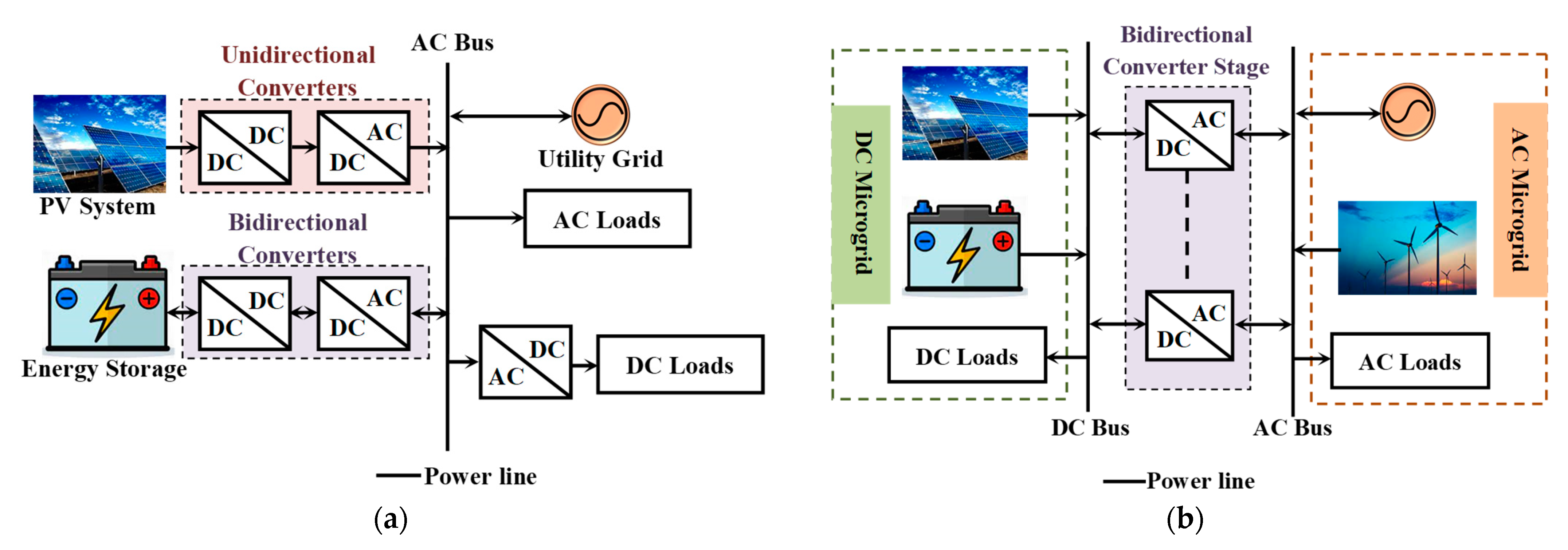
The hybrid MG and the AC MG required the bidirectional power transfer (BPT) approach out of the three MG structures shown in Figure 1. Therefore, one of the most crucial parts of the AC MG and hybrid MG systems, as illustrated in Figure 1, is the bidirectional power converters (BPCs), especially the bidirectional AC–DC converters (BADCs). BADC is a remarkable technique for combining an inverter and a rectifier in a single frame to achieve BPT while lowering the price, weight, and volume of the converter framework [14]. A bidirectional DC–DC converter and a BADC are used in AC MG systems, as shown in Figure 1a, to connect the ESSs to the AC bus in order to maintain the ESS’s charging and discharging phases [15]. An AC/DC hybrid MG, on the other hand, needs a BADC interface to integrate both AC and DC MGs by minimizing the AC/DC conversion stages and energy losses shown in Figure 1b [16,17]. Hence, the BADC interface’s ultimate purpose is to control the amount and direction of power between AC and DC MGs in accordance with the requirements and availability of power.
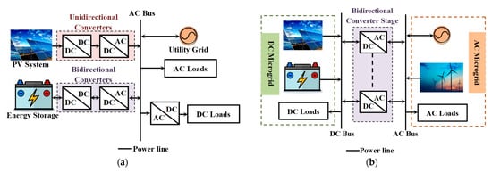
Figure 1.
Configurations of MG: (a) AC MG [7]; (b) hybrid AC–DC MG [18].
There are some features that all PE converters have in common. The two-level, three-phase, three-leg (3P3L) BADC topology based on pulse width modulation (PWM) shown in Figure 2 has great scope in MG systems as it ensures BPT [19]. The voltage source converter (VSC), which is frequently used as a crucial PE component for MG systems, possesses the inherent nonlinear dynamics and multi-timescale interactions of its outer and inner controllers [20]. The structure of the VSC is straightforward and flexible for a wide input and output voltage range [21]. Moreover, the converter has the ability to regulate the current in a sinusoidal waveform, making it simple to perform the unity power factor (PF) operation by adjusting the current in phase with the voltage [22]. The development of a dependable, efficient, and high-power density converter has become quite difficult as a result of the problems related to the harmonic content. This harmonic content has detrimental effects on the MG system’s power quality and stability [23]. Moreover, harmonic current levels of the input current may result in voltage distortion in the main supply, which may have negative impacts on other equipment connected to the same supply [24,25]. Therefore, the power that is produced and converted in the MG systems must follow grid regulations and meet all applicable national and international requirements for reliability, efficiency, and sustainability.
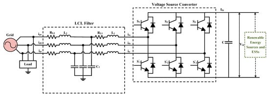
Figure 2.
Three-phase, Three-leg grid-connected BADC topology.
The converter controller plays a crucial role in the MG’s successful operation with smooth DC-link voltage, sinusoidal grid current, and reduced THD meeting IEEE standards. Numerous control strategies have been developed to achieve smooth bidirectional operation. However, the commonly employed strategies are direct power control (DPC), model predictive control (MPC), and voltage-oriented control (VOC). These control strategies have been implemented to reduce the harmonic content of the current that the converter delivers or takes from the power line. Based on the concept of instantaneous power, DPC provides a fast dynamic response due to the absence of the current control loop [26,27]. Although DPC has been recognized as a simple and stable control method for PWM-based converters, the two most prominent drawbacks are THD and variable switching frequency [28,29]. In addition, this type of controller requires a high inductance and sampling frequency. MPC is a nonlinear strategy with a multipurpose cost function that offers better efficiency and dynamic response, but stability, complex geometrical calculations to determine the duty cycles of the optimum voltage vectors, computational burden, and complexity are the core limitations of this model [30,31]. It also requires real-time optimization, which is more expensive and necessitates powerful computers, quick signal processing, and larger memory [32]. Therefore, an improved VOC method with active damping (AD), which is more convenient to implement than the above-mentioned methods, has been introduced in this study in order to realize BPT with improved system stability and power quality.
In [33], a development method for the grid-connected VSC based on VOC with an advanced phase lock loop (PLL) was proposed. However, this work was accomplished for an Lfiltered VSC, and the main focus was on PLL design. The disadvantages of L-filtered VSC compared to LCL-filtered VSC are increased expense, increased loss, the increased value of the inductor, and huge weight and volume [34,35]. As a result, in high-power and low-frequency systems, the LCL filter is used instead of the L filter to smooth the output current of the converter by reducing switching current ripple and ensuring high steady-state and dynamic performance of the entire system with lower inductor values [36,37]. However, the complex conjugate resonance poles of the LCL filter reduce the effectiveness of the system. With either VSC-side or grid-side current control, the LCL filters’ inherent resonance has a tendency to oscillate the system response without any damping. Additionally, because of this inherent resonance effect, even low voltages at frequencies near the resonance can generate currents of very large magnitudes because of the extremely low impedance at those frequencies [38]. As a result, it can be difficult for the converter system to attain closed-loop stability because of the potential variation in the resonance frequency. Passive damping and AD techniques are used to reduce the high-order filters’ resonance problem [39]. A better control technique for the LCL-filtered grid-connected inverter with space vector pulse-width modulation (SVPWM) was proposed in [40] in order to reduce the current harmonics. To lessen the impact of harmonics, scaling errors, and DC offset on the main grid current performance, another LCL-filtered inverter with an improved current management strategy based on VOC was proposed in [41]. On the basis of an analysis of the mathematical model of a grid-connected inverter with an LCL filter, a decoupling control of the inner current control loop (ICCL) was proposed in [42] to address the issues of complex models and severe coupling of LCL filters in the dq-coordinate system. In order to suppress the harmonic orders of the grid voltage, the discrete-time VOC scheme was developed in [43]. The controller was constructed in the synchronous reference frame (SRF) with proportional-integral (PI) and multi-resonant controllers. Using hardware-in-the-loop, the converter framework’s performance was verified. However, all the aforementioned studies of the LCL-filtered VSC adopted the traditional VOC scheme with a damping resistor. Passive damping using a resistor is not applicable for high-power applications due to the additional power loss. The damping resistor lowers the quality factor in passive damping systems, and a higher value of the filter capacitor is also required to reduce grid current harmonics and improve the controller’s dynamic performance. This higher value of the capacitor and damping resistor associated with the capacitor increases the LCL filter size and system loss, decreases the system resonance frequency, and affects the controller’s performance [40]. Moreover, determining the ideal resistor value to lower the peak resonance of the LCL filter is crucial in passive damping [39]. Therefore, an AD method is used in this study to avoid additional power losses and increase system reliability. Adding the voltage or current of the filter capacitor feedback in the controller using a virtual gain by substituting the physical damping resistor can typically serve as the AD [44,45,46]. A capacitor voltage feedback (CVF)-based AD method with a high-pass filter was used in [47] to mitigate the resonance, but additional analysis is required to mitigate the impacts of the cutoff frequency of the high-pass filter along with virtual gain on system stability. This damping technique needs derivative feedback of the capacitor voltage to provide the intended resonance damping, but in practice, pure derivative implementation has always been constrained by noise amplification at high frequencies, and this method also adds additional computational delay to the system [44]. These problems can be overcome by feeding back capacitor current rather than voltage [48].
Proportional capacitor–current-feedback (CCF) AD control with an unreliable second-order phase lead compensator was introduced in [49] to reduce the adverse effects caused by the digital control delay and to ensure system stability. In order to minimize negative resistance behavior, reduce the time delay from the capacitor-current loop, and maintain system stability, the CCF damping method with compensation method was proposed in [50]. However, from a practical point of view, the use of a current sensor can be more expensive than a voltage sensor for high-power commercial applications [44]. Moreover, the measurement of filter capacitor current is quite challenging due to the noise sensitivity and very low magnitude of capacitor current. As a lower filter capacitor value results in low-magnitude current, in practice, it is difficult for any current sensor to accurately sense such low-magnitude current components. Furthermore, the feedback loop typically needs a low-pass filter in practical applications, which increases the complexity of the control system [47]. These practical problems have not been considered in the aforementioned studies. Therefore, in this study, an observer-based AD approach is proposed to overcome the challenges of the direct CCF method.
With the proposed technique, the capacitor current is estimated from the capacitor voltage using a state observer, and the estimated capacitor current is then connected to the controller to achieve AD. This work contributes to AD capability improvement by having predicted filter capacitor current employing the Luenberger observer that is then passed through a virtual gain to produce a damping effect on the LCL resonance compared to the direct CCF method. The proposed control system provides better THD and dynamic performance with a lower value of the capacitor and maintains the system resonance frequency within the system stability limit without any damping resistor. The inclusion of non-linear loads affects the voltage, causing harmonics; therefore, the system may operate with both linear and non-linear loads as well as harmonics and grid voltage distortion. The main advantage of the proposed current control scheme is that it provides better harmonics, a more dynamic system, better performance with nonlinear loads, and more stability with a lower value of the filter capacitor and eliminates the practical application complexity associated with capacitor current measurement.
The following are the main contributions of this paper:
- A VOC scheme with AD, feedforward, and decoupling techniques is proposed and implemented in synchronous -coordinates in order to realize BPT with improved system stability and power quality.
- An observer-based AD is also developed in order to reduce the resonance effect of the LCL filter, improve the system stability, and eliminate the power losses due to passive damping.
- The performance of the BADC system with the designed controller has been tested in a RT simulation environment for a 16 kVA BADC system using the OPAL-RT platform. The designed converter can handle both linear and non-linear loads and operate in rectifier and inverter modes while keeping the THD value within the permitted limit.
- This study also presents a comparative study of some previously introduced controllers and a proposed VOC scheme with observer-based AD in terms of power quality.
This paper is formulated accordingly. Section 2 represents the configuration of the BADC system with a VOC scheme based on the proposed current controller with observer-based AD. Section 3 presents the mathematical modeling of the proposed system. The characteristics of the employed PLL and LCL-filtered system with the proposed controller have also been analyzed in Section 4. The results obtained from the RT-SIL platform have been illustrated, and a brief comparative study among various controllers and a suggested VOC scheme have been presented in Section 5. Lastly, Section 6 concludes the paper with key findings.
2. System Description
The configuration of the 3P3L BADC based on the proposed controller is presented in Figure 3. The specifications and required parameters to design the 16 kVA converter system using the proposed current controller are listed in Table 1. The BPC system’s primary function is to supply local loads with power while transferring any extra power to the main grid and vice versa. VSC, LCL filter, utility grid, DC-link capacitor, and linear or non-linear loads are all integrated into the converter design. The utility grid considered in this study is ideal, and the grid voltage () only contains positive-sequence fundamental components. The VSC consists of six IGBT switches with a free-wheeling diode, and it is linked to the main grid or loads by an LCL filter. The function of VSC is to convert and transfer the required power according to demand. Two examples of DC energy sources that can be employed as the source of DC voltage are a battery bank or a photovoltaic (PV) array, and this DC voltage source supports the DC-link voltage (VDC) of the converter. The LCL filter reduces the harmonic content of the sinusoidal current. The filter consists of a grid-side inductor L2, a filter capacitor Cf, and a VSC-side inductor L1. RL1 and RL2 are, respectively, the equivalent series resistances of the VSC-side inductor and grid-side inductor. The DC-link capacitor (C) ensures a constant and smooth DC voltage.
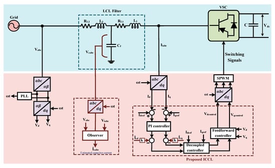
Figure 3.
Configuration of three-phase BADC with suggested control strategy.

Table 1.
Dataset used in the proposed work.
The grid-connected VSC system is generally controlled and operated with a predetermined operating frequency that is imposed by the AC main system. In this paper, the converter system is controlled by the VOC technique. This VOC method for converters is derived from field-oriented control (FOC) for induction motors. FOC offers a quick dynamic response due to the utilization of current control loops [51]. The VOC is one of the most widely employed control schemes in the BADC system because of its better performance in terms of stability and harmonic content [52]. It helps to obtain a constant switching frequency. It is extensively utilized in grid-connected converters due to its high static and dynamic performance in regulating the grid-current. Coordinated transformation, PLL, and decoupled control are the key ideas of a VOC-based grid-connected converter.
The VSC system is controlled in a -frame, as shown in Figure 3. In order to create the necessary control signals in the -frame, the feedback and feed-forward signals are therefore changed in the -frame using coordinated transformation and processed by the respective control loops. PLL is implemented to estimate or trace the phase and frequency of the grid voltage or to offer information to attain grid synchronization between the grid infrastructure and the converter system [53]. Synchronization between the converters and the grid involves detecting accurate phase details of the grid voltages [1]. For the grid-connected VSC to achieve decoupled active and reactive power management, the PLL is one of the most important components of the system. The SRF-PLL used in this study is one of the PLLs with the best performance and fastest speed response [54]. The decoupled controller includes the negative d-axis element and positive q-axis element of the VSC-side current, multiplied by their respective inductive reactance, which is added to the output of the current regulators. The control system uses the PWM technique to make sure that the features of the VOC control system are varied. Sinusoidal PWM (SPWM) is a category of PWM techniques used to produce gating signals for the IGBT switches in the VSC [55]. This method compares a low-frequency sinusoidal modulating signal to a high-frequency triangular carrier signal to perform the modulation process. The amplitude and frequency of a reference or modulating signal are continuously changed to produce the desired output voltage. When the two signals interact, pulses with different duty cycles are formed. The switching times for each switching state of a certain variable are determined by the intersecting points. The switching operation of the switching devices in each leg of the VSC is controlled by the pulses that are produced. The concept of decoupled control is formulated according to the decoupling of the ac current into active and reactive current elements in the synchronous reference frame (SRF). These current elements are controlled to reduce the error between the computed and reference quantities of the active and reactive powers [40].
3. Controller Configuration and Mathematical Modeling
The grid-connected VSC system’s control is converted into control of the real and reactive power that the VSC system exchanges with the AC main system using the VOC strategy based on a current-mode control approach. An improved current control approach based on VOC and an observer-based AD system are introduced in this section to improve grid current quality and reduce the resonance problem of the LCL filter. In this study, there are three primary stages of a VSC control scheme: the current reference generator, the observer design for the estimation of capacitor current, and the current controller.
3.1. Current Reference Generator
The DC-link voltage control is not used because the main objective of this study is to assess the suggested current controller’s control performance in the PQ control (grid following) mode of operation. However, the proposed controller can perform equally if a voltage controller is added and the reference current can obtain from the voltage control loop. A current reference generator is simply designed to generate the reference current [56]. Based on the desired active and reactive power and grid voltage, the current references for the ICCL can be produced in the -reference frame [57]. The active and reactive power equations are as follows:
Here, Pg and Qg are the active and reactive power; and represent the active and reactive components of the grid voltage in the -frame; and Id and Iq signify the active and reactive components of the grid current, respectively. For the balanced condition ( = 0), Equation (1) will be as follows:
Here, and denote the reference active and reactive components for the ICCL.
In this study, the ideal condition of grid voltage (Vg) is considered where Vg is pure sinusoidal; hence, the magnitude of is constant in the -frame.
3.2. Current Controller Design
The ICCL is established based on the decoupled active (Id) and reactive (Iq) current elements in the -coordinate. In most cases, Id is controlled using VDC aimed at maintaining the active power transfer, and Iq is controlled to maintain the PF close to unity.
Figure 4 depicts a three-phase grid-connected VSC with an LCL filter in a single-phase equivalent circuit. According to Figure 4, the mathematical modeling of the BADC with an LCL filter in the frame is expressed as Equation (3).
where, is the grid voltage, is the filter capacitor voltage, is the VSC-side voltage, is the grid-side current, is the VSC-side current, is the capacitor current.
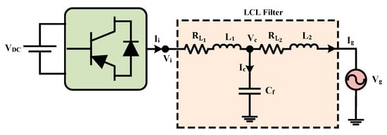
Figure 4.
Single-phase equivalent circuit of three-phase BADC with LCL filter.
For the balanced three-phase system, there is no zero-sequence current component. So, the system can be regulated in the stationary αβ-frame. The representation of the three-phase system of Equation (3) in two components of a stationary αβ reference frame () using the Park transformation [58].
Equation (4) represents the LCL-filtered BADC system in the αβ-reference frame. The design of the ICCL is performed in the SRF, where everything is DC. The controller design and parameter tuning are carried out in the SRF because working with DC systems is comparatively simple. The -control configuration is obtained using the Park and Clark () transformation block to convert the control quantities from or αβ-frame to -frame, which rotates synchronously with the grid voltage frequency [59]. Using the Clark transformation, Equation (4) can be expressed in the -frame (SRF) by neglecting the decoupling terms of d and q components as depicted in Equation (5)
Equation (5) is transformed to the Laplace domain (s-domain) as presented in Equation (6), where s is the Laplace operator.
The LCL filter-based BADC framework is presented in the -frame with the help of a block diagram shown in Figure 5 using Equation (6).
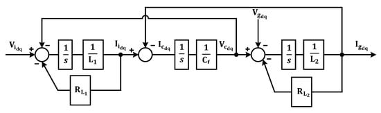
Figure 5.
Illustration of block diagram of LCL-filtered BADC system in -frame.
With either VSC-side or grid-side current control, the LCL filters’ inherent resonance causes system instability without any damping. Therefore, PD and AD are used to solve the resonance problems. The appropriate damping of resonance effects can be obtained using AD in the considered LCL-filtered system. A crucial transfer function in the design of a LCL-filtered system is is the transfer function of the grid-side current and VSC-side voltage, as illustrated in Figure 5. In the computation of the LCL filter transfer function, the grid voltage is considered an ideal voltage source that can damp all harmonic frequencies. The transfer function of the LCL filter can be found assuming Vg is equal to 0 (a clean grid) under the current-controlled VSC.
Based on the model provided in Figure 4, the transfer function of the LCL filter without damping () can be obtained as (7).
The current controller proposed in this paper provides the necessary damping or reduces the resonance issues of the LCL filter with the help of the CCF AD. The capacitor current is used as CCF damping in the system and reduces the resonance peak of the LCL filter. This feedback system provides system stability. Based on this AD model, the transfer function of the LCL filter with the proposed control system can be obtained as (8).
where k is the simple proportional gain associated with the capacitor current.
In both cases, the angular resonance frequency () will be as follows:
The control equations of the PI-based VOC structure with AD are presented in Equations (10) and (11).
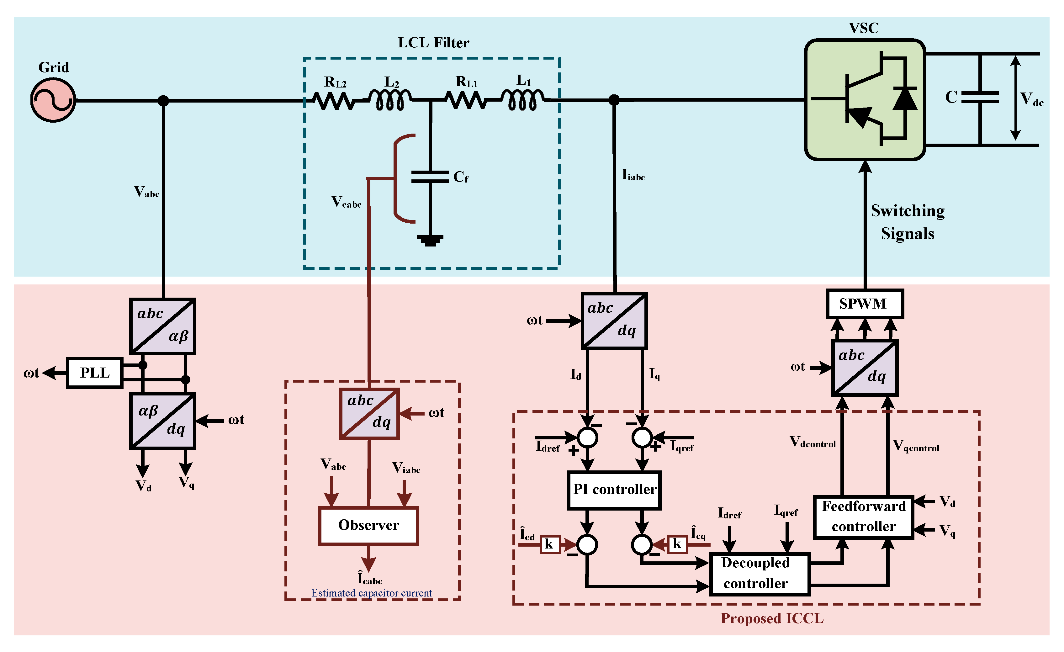
The block diagram presented in Figure 6a represents the control strategy of the LCL-filtered BADC system, which is based on AD and PI controller-based VOC in synchronous -coordinate. ω is the angular frequency of the utility grid, and the synchronous reference frame is rotating at this angular frequency. The AD is implemented by sensing the capacitor current, multiplying it by the constant k, and subtracting the outcome from the output of the PI controller. Equations (10) and (11) are the control equations of the AD-based ICCL. These equations are utilized to develop the control block of the ICCL, i.e., the suggested VOC scheme. The configuration of the ICCL of the BADC is depicted in Figure 6, which has been developed based on Equations (10) and (11). In Figure 6, there are two decoupling terms in both the d- and q-axis elements, which are associated with VSC-side current, respectively. There is another additional block associated with the capacitor current. This block eliminates the resonance problem of the LCL filter and ensures system stability without any damping resistor by using the CCF with a proportional gain k. In order to incorporate these elements of the capacitor current in the controller, the suggested ICCL structure involves an additional sensor. Feedforward control with grid voltage provides a faster dynamic response. In Figure 6, the currents and are utilized in the decoupled controller of the VSC current by replacing Id and Iq, respectively. This simple consideration enhances the quality or reduces the harmonic content of the grid current and speeds up the dynamic response of the grid-connected VSC. These decoupling and feedforward strategies have been adopted to provide a faster dynamic and smoother transient response. The feedforward controller (adding and term) also improves the tracking performance of the controller.
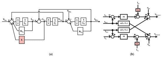
Figure 6.
(a) Illustration of block diagram of the AD-based LCL-filtered BADC system in -frame VOC scheme with proposed ICCL. (b) Illustration of VOC control structure with AD.
The control strategy is regulated by a group of PI controllers, which require optimum tuning to ensure smooth operation. The parameters of the PI controller, = 44 and = 350 are tuned using the trial-and-error method and considering the performance of the converter and system parameters. The control signals are then sent to the PWM scheme of the VSC after being translated into the frame.
However, the direct measurement of capacitor current is quite challenging in practice. In order to solve this problem, the current controller for the considered LCL-filtered system is designed using an observer-based AD system. In this study, observer-based AD is considered instead of direct CCF AD to damp the resonance effects of the LCL filter and improve system stability. The AD is implemented by sensing the capacitor voltage and estimating the capacitor current from that voltage using a Luenberger observer. Therefore, an observer is essential to design the proposed control system. The single-phase equivalent circuit of the BADC with LCL filter in Figure 4 and Equation (6) represents the BADC system in the continuous state-space model [38].
Here,
x is the state vector with three state variables (, , ), where and are the grid-side and converter-side currents, and is the voltage across the filter capacitor. u is the system’s input vector with two variables (, ). A is the system or state matrix, B is the input matrix, and C is the output matrix of the system. As in this study, the capacitor voltage is considered to estimate the filter capacitor current; therefore, the output matrix for the capacitor voltage is . The dynamics of the capacitor current () can be characterized in the state-space model using Equation (13).
Specifically, to design the Luenberger observer, the output of the observer is subtracted from the output of the main plant model and then multiplied by a matrix L, which is illustrated in Equation (14). To separate the state observer’s variables from the physical system’s variables, the observer’s variables are symbolized by and . That is, the superscript “ˆ” signifies the predicted value. In order to design the observer, the grid voltage and capacitor voltage are used. An observer for the LCL filter system Luenberger observer state is designed using Equation (14).
Here, L denotes the observer feedback gain matrix, while signifies measured states vector (in this study, grid voltage and capacitor voltage). In matrix L, only the value of element is considered, as the significance of the other elements can be neglected. Since the system is observable, as evidenced by the observability matrix in Equation (15), whose rank is not zero, the observer’s eigenvalues can be allocated arbitrarily, and AD can be considered independently. The poles of the closed-loop observer error dynamics are placed at appropriate positions using the observer gain matrix L.
With Equation (16), the dynamic of the estimation error (is
The characteristic polynomial in Equation (17) determines the observer dynamics. The poles of the polynomial calculate the values of the observer gain matrix.
In s domain
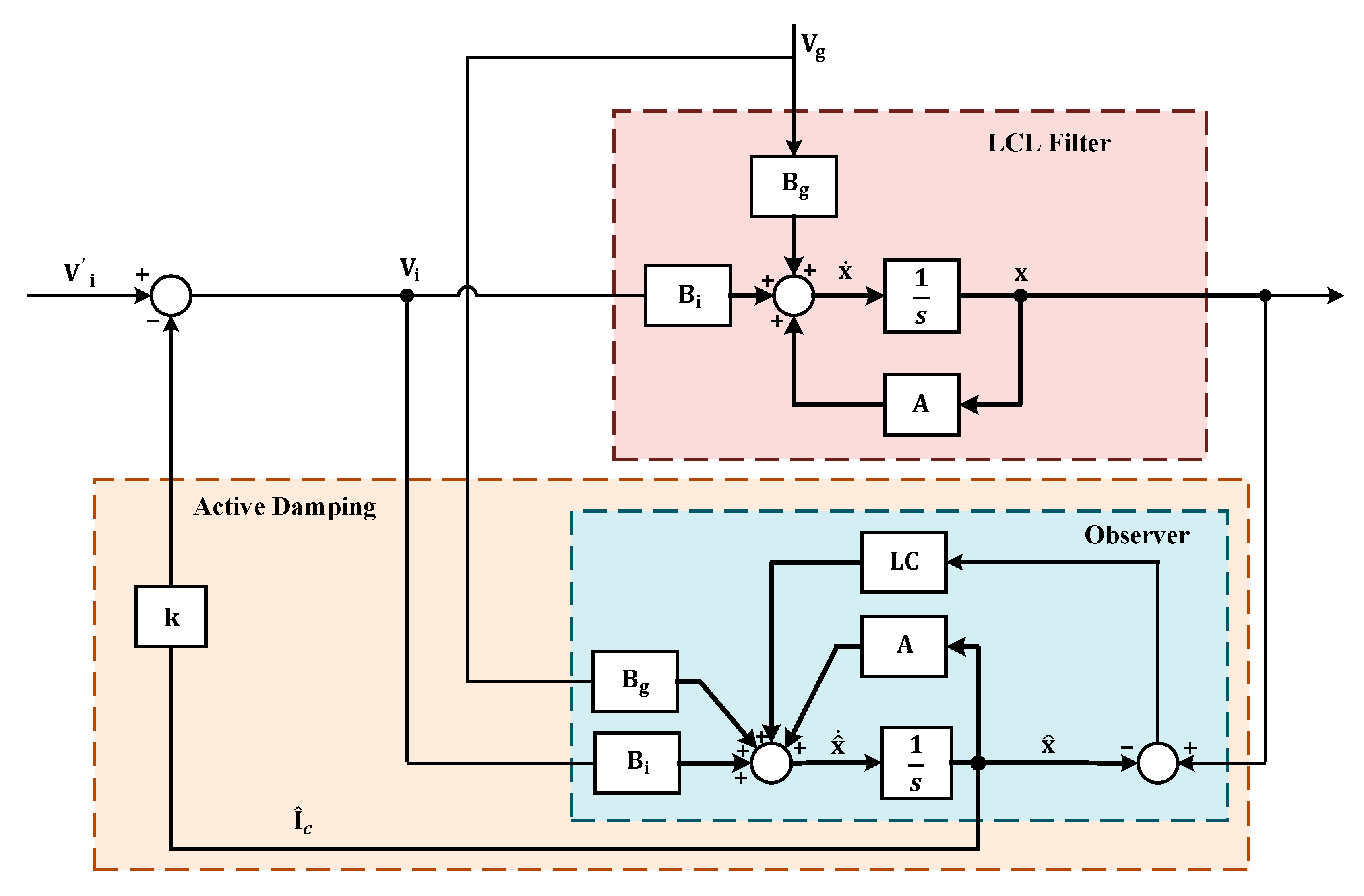
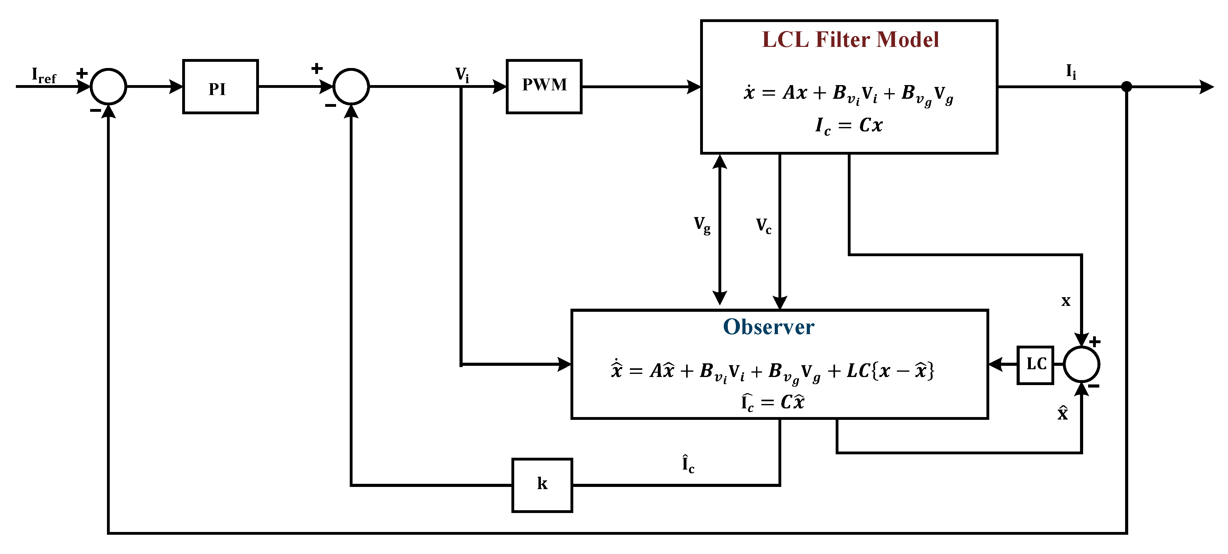
The Luenberger observer is asymptotically stable when the matrix ( in continuous-time) or Equation (17) has all the eigenvalues on the left-side of the s plane. Moreover, the eigenvalues (poles) of the matrix () or Equation (17) can be selected randomly by properly selecting the observer gain L as the system is observable. Figure 7 shows the proposed AD using CCF, in which capacitor current is measured using an observer and provides great damping capability. In this method, a closed-loop Luenberger observer is used to estimate states in advance, and then the anticipated filter capacitor current is employed to attain damping.
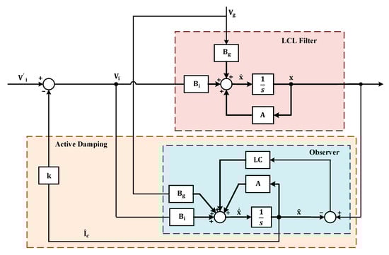
Figure 7.
Suggested observer-based AD utilizing estimated state as feedback.
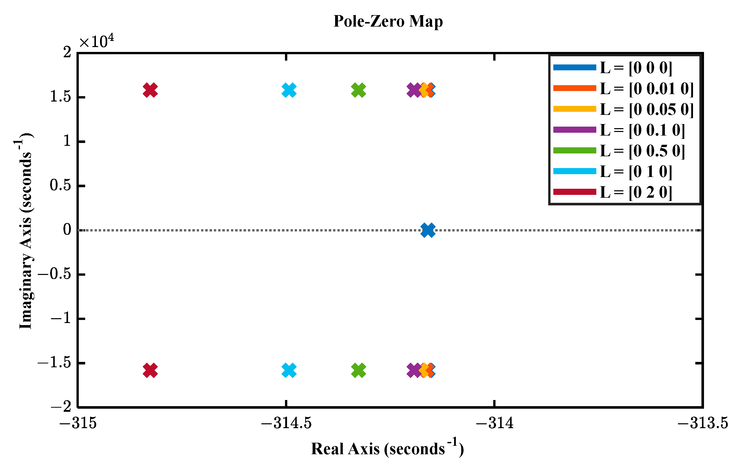
Figure 8 shows closed-loop observer eigenvalues (pole placement) as the function of the observer gain matrix L. L determines the dynamic characteristics of the observer and is also utilized for faster convergence of the estimation to the actual value. The observer’s roots are on the left-side of the s plane, as shown in Figure 8 when L = [0 0 0], but when L rises, the roots move further in the left-side of the s plane. The linear Luenberger observer quickly converges to the system states when the observer gain, L is larger. However, a peaking phenomenon caused by high observer gain can make the initial estimator error practically prohibitable or unsafe. This paper considers L = [0 0.05 0] to avoid the peaking phenomenon. The observer has quick dynamics; the roots are on the left side of the s plane for L = [0 0.05 0], which is preferable to prevent forced oscillations and protect the system from peaking phenomena or unsafe operation. Moreover, it is the best option because the roots are in a suitable position on the s plane.
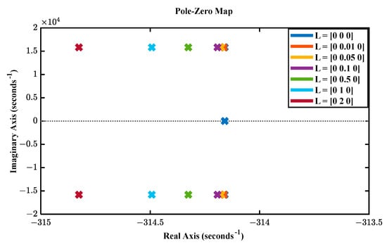
Figure 8.
Observer eigenvalues plot in s domain.
A detailed block diagram of the VOC-based current controller with observer-based AD for LCL filter is presented in Figure 9. It consists of an AD loop, a current controller, and PWM. The input variables of the observer are and . is the voltage obtained from the converter current controller. The PI controller minimized errors between reference and measured VSC-side currents. The LCL filter capacitor voltage () is used to estimate the capacitor current to eliminate the current measurement difficulties. Then, the estimated capacitor current () with multiplier k is subtracted from the converter current controller voltage to obtain the necessary damping. k is the proportional gain (virtual resistor), which mimics the behavior of an actual damping resistor without increasing the system’s power losses or burden.
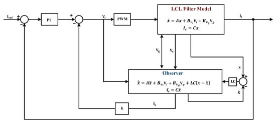
Figure 9.
Detail diagram of the VOC-based current controller with observer-based AD.
4. System Characteristics
This section demonstrates the performance and stability of the converter system with the proposed ICCL.
4.1. PLL Characteristics
A PLL is a nonlinear closed-loop feedback system that synchronizes its output signal with an input signal in both frequency and phase. In grid-connected systems, the SRF-PLL is a frequently utilized synchronization method due to its benefits, such as its simple structure and reliable performance. Under optimal grid conditions, the SRF-PLL offers quick and precise frequency/phase detection [60]. The phase detector (PD), loop filter (LF), and voltage-controlled oscillator (VCO) are the three fundamental components of a PLL, as shown in Figure 10. The PD generates the phase error information. LF is a PI controller that lessens the high-frequency components of the PD-generated output. VCO produces the estimated phase () that tracks the actual phase of the grid voltage [54]. In SRF-PLL, the grid voltage is converted to the reference frame with the help of both Clark and Park transformations. The d- or q-component is controlled to become zero by employing a feedback loop to regulate the angle of the -frame. As optimum grid conditions are considered in this study, the SRF-PLL produces reasonable performance in terms of dynamic response and frequency/phase tracking capability.
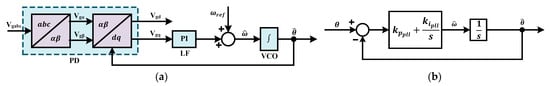
Figure 10.
(a) Configuration of SRF-PLL [60], (b) small-signal model of PLL [54].
The closed response of the PLL
Here, s is the Laplace operator, is the actual phase angle, is the estimated phase angle, is the estimated angular frequency, and is the nominal angular frequency, and are the parameters of the PLL’s PI controller.
Representing Equation (18) in terms of its natural damping factor (ζ) and damping frequency () [61].
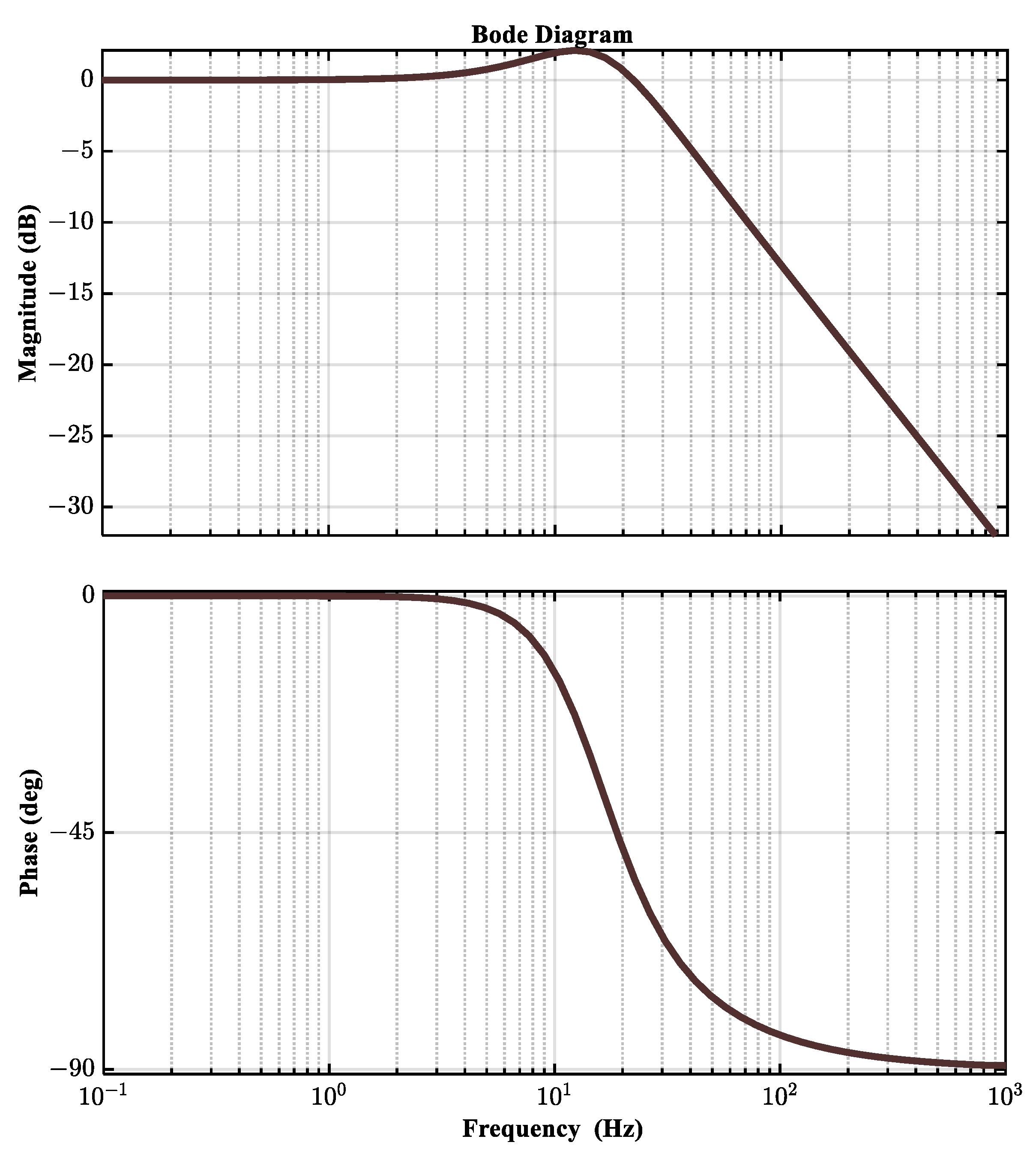
From Equations (18) and (19), and . In this study, optimal damping condition is considered with and . Figure 11 represents the frequency response of the PLL. Gain and phase are both zero at low frequencies. Gain tends to drop, and phase shifts tend to increase as frequency rises. The closed-loop response of the PLL illustrates that the employed PLL with the considered parameters is stable. The bandwidth of the closed loop system is 31 Hz, as indicated in Figure 11.
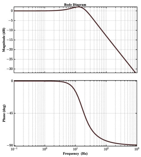
Figure 11.
Bode plot of the frequency response of the SRF-PLL.
4.2. PI Controller Tuning and System Stability Analysis
The PE converters’ switching components or the PWM’s high-frequency switching make it difficult to achieve the grid connection condition because of current harmonics. This issue can be resolved by connecting the PE converters to the main grid via a filter (L, LC, and LCL) in order to smooth out the current injected into the loads or the grid [62]. In grid-connected VSC, higher-order filters, like LCL (third-order), are more frequently used as an interface element to reduce switching harmonics. In applications exceeding several kWs, a third-order LCL filter has a lower cost and smaller size than a first- and second-order filter [63]. However, the resonance effect of the LCL filter causes system instability. Therefore, an observer-based AD method using CCF has been used in this study to improve system stability.
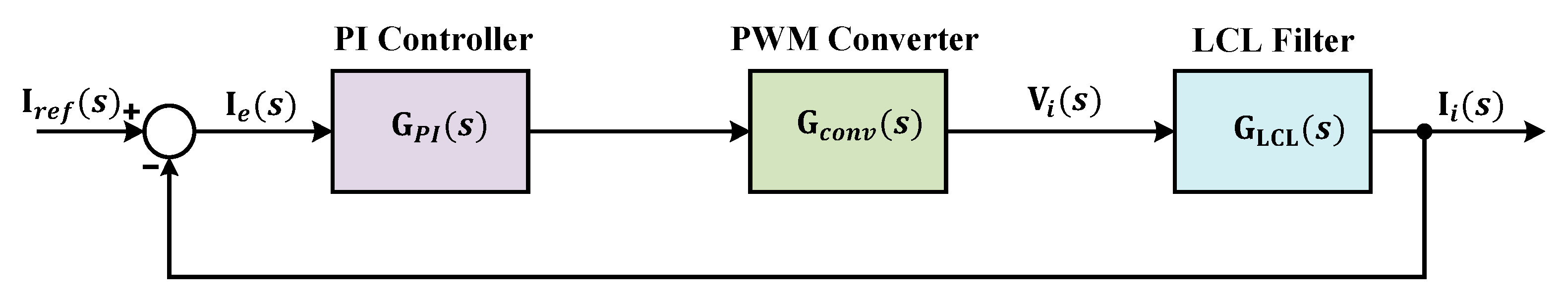
The s-domain control model of the whole BADC system depicted in Figure 12 is constructed to analyze the resonance and stability problems of the system. The control strategy is regulated by a group of PI controllers, which require optimum tuning to ensure smooth operation. is the transfer function of the PI controller. In LCL-filtered converter systems, the PI controller under the reference frame is frequently employed to precisely track the reference current.
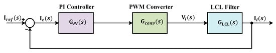
Figure 12.
Block diagram of BADC system in s-domain.
Here, and are the proportional and integral gains of the PI controller. The parameters of the PI controller, = 44 and = 350 are tuned using the Ziegler–Nichols method and considering the converter’s performance and system parameters. The step response of the system with the PI controller is presented in Figure 13. At = 1 and = 1, the rise time of the system is higher. With the increase in the value of , the overshoot of the system increases. In order to decrease the overshoot, the value of the is increased.
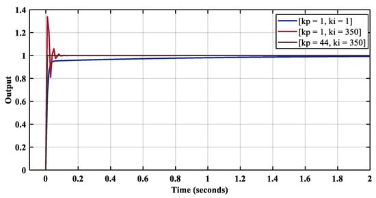
Figure 13.
Step response of the system with PI controller.
The BADC model also includes the PWM modulator delay as well as the sampling and calculation times of the converter system as pure time delays (). is the transfer function of the delay associated with the converter system. In the Laplace domain, an represents this time delay, . A first-order lag approximation, i.e., is used in place of in the system modeling and controller design to account for the influence of control delay.
signifies the delay due to the controller, the PWM modulator, and the necessary conversions, as previously described. In most cases, this delay has a small value. In this study, . signifies the sampling time (100 μs).
The feedback configuration of the estimated capacitor current in the LCL filter block diagram is developed to address the issue related to resonance. The goal of using this controller is to lessen the attenuation and damping (quality factor) at the typical resonance frequency. The detailed system configuration of the proposed controller with CCF has been presented in Figure 14.
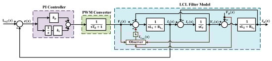
Figure 14.
Illustration of mathematical model of the proposed current controller in s-domain.
The open-loop and closed-loop transfer functions for the current control scheme shown in Figure 12 and Figure 14 can be simply obtained from the combination of the three transfer functions as Equations (22) and (23) in the s-domain for the control system analysis, like frequency response analysis.
Here,
,
,
,
,
,
,
.
Equations (22) and (23) help to generate a detailed stability analysis based on the frequency responses of the open-loop gain and closed-loop transfer function in the MATLAB environment for the control system to obtain the connection among the ICCL stability, the inherent resonance of the LCL filter, and AD using the system configuration presented in Table 1 and different values of virtual gain (k).
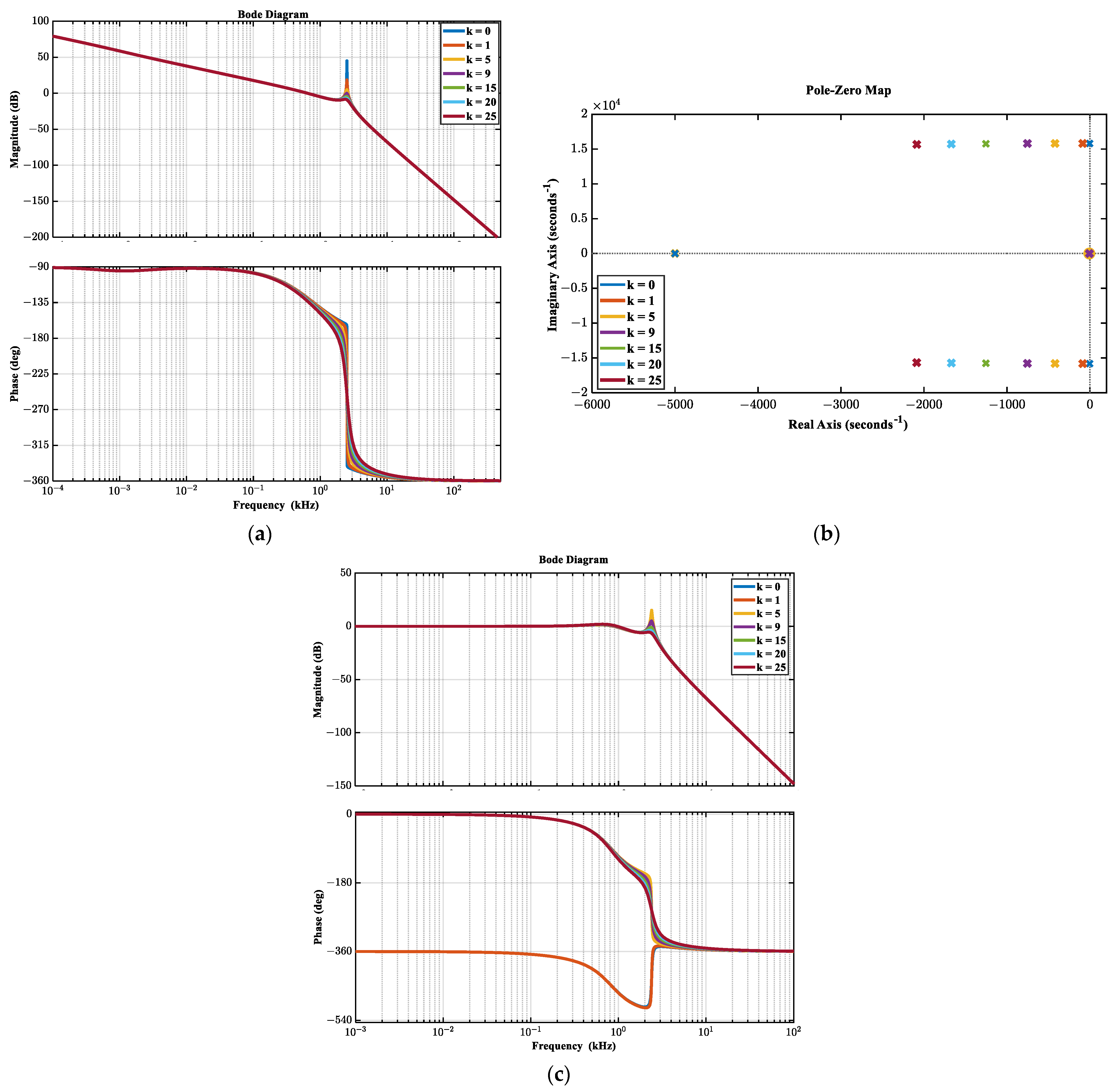
Figure 15 displays the system response of the LCL-filtered converter system. Due to the third-order configuration of the LCL filter and the lack of damping, there is a gain spike or large overshoot at the resonance frequency ( = 2054 Hz), and phase plot is −360 degrees. By adding feedback of the capacitor current through the observer in the controller, the gain spike is eliminated, the overall response is smoothed down, and the high-frequency rolling-off is reduced to −180 degrees from −270 degrees with the increase of k. All these figures ensure the stability of the proposed system. Figure 15a,b illustrates the bode plots and pole-zero maps of open-loop gain of the whole system presented in Figure 15 for seven different values of virtual gain (k). Figure 15c illustrates the closed-loop characteristics of the system. At k equals 0 (without damping) and 1, the phase is at −360 degrees instead of 90 degrees, and there is a large spike in magnitude at the resonance frequency, as illustrated in Figure 15a,c. With the increase in k, the phase and magnitude settle into the appropriate values. However, the value of k must be greater than 9 for the mentioned system parameters to maintain system stability with satisfactory damping performance. As virtual gain increases, damping of the resonant poles effectively increases without limitation, and system stability increases. Here, it should be mentioned that in this AD method, the quantity (multiplication of virtual gain and estimated capacitor current), as shown in Figure 6, is deducted from the converter voltage according to Equations (10) and (11). Therefore, the value of k should not be too large in order to prevent a significant converter voltage drop. The value of k is often chosen so that it does not exceed 10% of the converter voltage [64]. In this study, k should not be higher than 30, based on this criterion of converter voltage. So, from the analysis, it can be noted that in order to ensure system stability and better performance, the satisfactory variation range of k should be from 9 to 30. The gain margin must be larger than 9 dB, and the phase margin must be between 45 degrees and 65 degrees to guarantee proper dynamic performances and adequate stability margins of a system. Moreover, a larger value of k permits a large grid inductance variation, i.e., gain margin and phase margin values are in the above-mentioned limit for larger grid inductance [64]. However, the large variation in grid inductance increases the system THD. The THD is within limits for variation up to 2 mH. In this study, k = 20 is considered based on the values of the PI controller, grid inductance effect, and controller time delay to ensure the required gain margin and phase margin values. At k = 20, the gain margin is 9.17 dB, the phase margin is 47.6 degrees, and the grid inductance variation is up to 0.5 mH. The value of k less than 20 causes the gain margin to decrease by less than 9 dB and decreases the grid inductance variation limit, and the value greater than 25 starts to reduce converter voltage. Therefore, in order to maintain a gain margin greater than 9 dB, grid inductance variation limits, and converter voltage within range, k = 20 is considered.
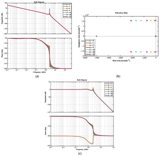
Figure 15.
System responses for different values of k: (a) bode diagram of the open loop system, (b) Pole zero map of the open loop system, (c) closed-loop system response.
5. Results and Analyses
This section demonstrates the performance and effectiveness of the control strategy based on the proposed AD-based ICCL for both the rectifier and inverter modes using the MATLAB/Simulink and OPAL-RT simulator for RT simulation. System parameters listed in Table 1 are utilized to perform the RT simulation.
5.1. Real-Time Simulation
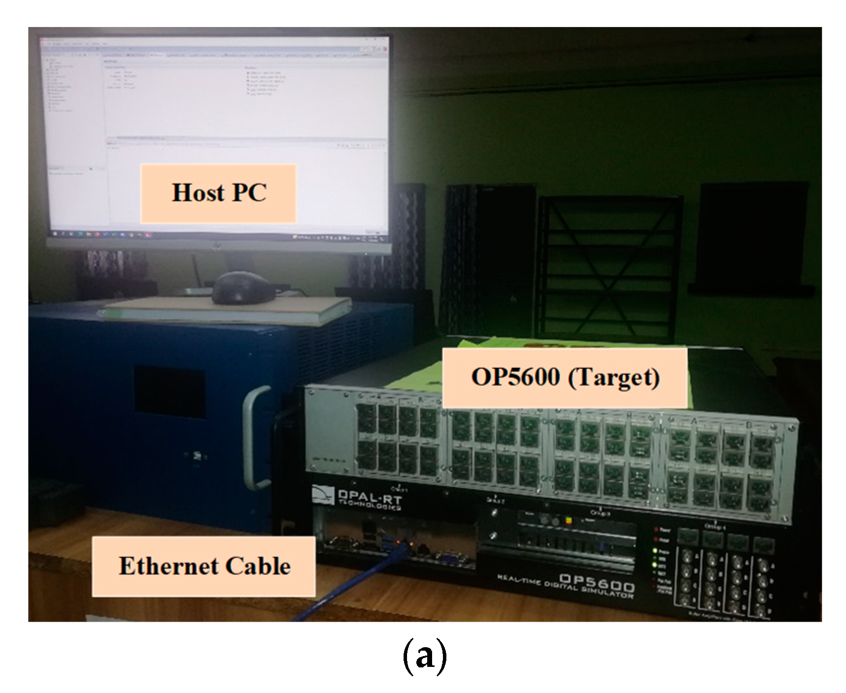
The OPAL-RT platform for RT simulation is used as an initial step toward experimental validation. This platform, often called the RT SIL simulation, is used to demonstrate the feasibility of RT simulation for both small- and large-scale systems. Simulink models can easily be turned into real-time workshops with this technology. The experimental set-up, which includes the host PC and the OPAL-RT simulator as the target, is shown in Figure 16a, and it is located at the Advance Power System Research Laboratory, Chittagong University of Engineering and Technology. OP5600 has been used as the OPAL-RT platform, a full-featured simulation system that can run on Virtex-6 or Spartan-3 FPGA systems and is intended to be used as a typical rack mount or as a shelf top. It runs under the Linux operating system and has four activated Intel Xeon E5 processor cores clocked at 3.2 GHz.
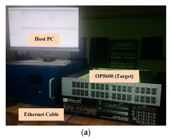
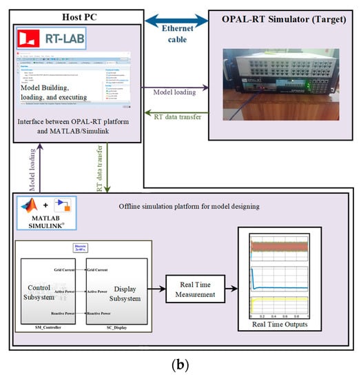
Figure 16.
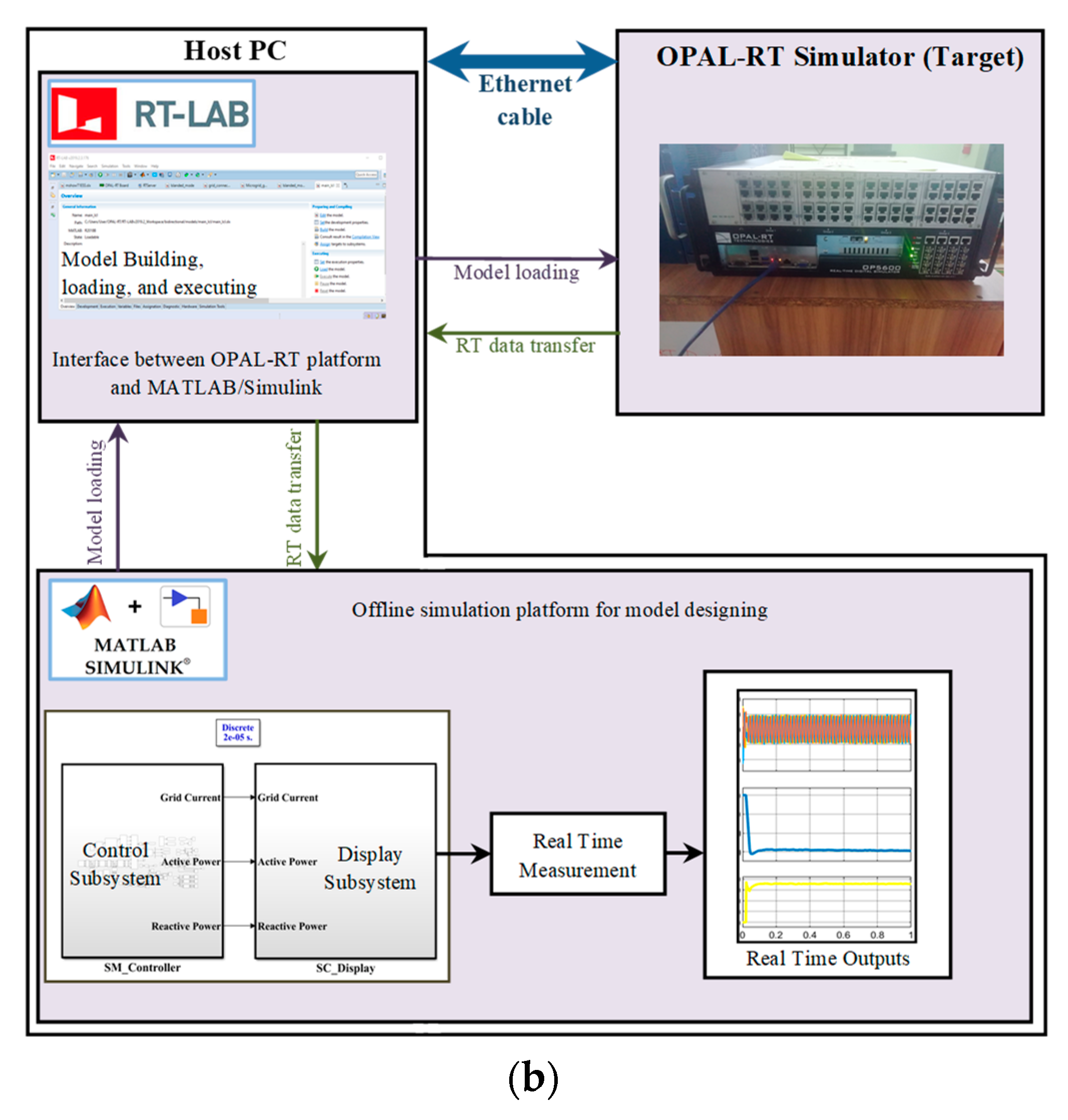
Real-time SIL setup: (a) real-time SIL setup including host PC, Ethernet cable, and OP5600 target; (b) process of real-time SIL with OPAL-RT platform.
The RT-SIL simulation procedure is displayed in Figure 16b. The OPAL-RT platform and MATLAB/Simulink communicate with one another via the RT-LAB software (version 2019.2.3.176), which is fully integrated with MATLAB/Simulink and allows Simulink models to communicate with the real environment in RT. It offers scalable and adaptable solutions as a multi-domain platform for PE and power systems. The MATLAB/Simulink model is loaded on the OPAL-RT simulator via the RT-LAB software, and then the RT data is returned to the MATLAB/Simulink environment. A subsystem containing all power and control components and a subsystem incorporating displays should be created in the Simulink model. The user can keep track of the system while it is operating via the Display subsystem, and the controller subsystem includes the proposed control loop and the converter models. The OpComm blocks from RT-LAB’s Simulink library are introduced to make the communication link between the subsystems easier. RT-LAB software is then used to build and compile the prepared model into executable codes, which are subsequently loaded and run in OP5600 on several powerful processors. In the MATLAB/Simulink environment, RT waveforms can be measured after receiving model loading and RT data.
5.2. Simulation Results
The RT SIL with OPAL-RT platform shown in Figure 16 was used to collect the necessary output waveforms required for this work. All simulations are performed with a sampling frequency of 50 kHz.
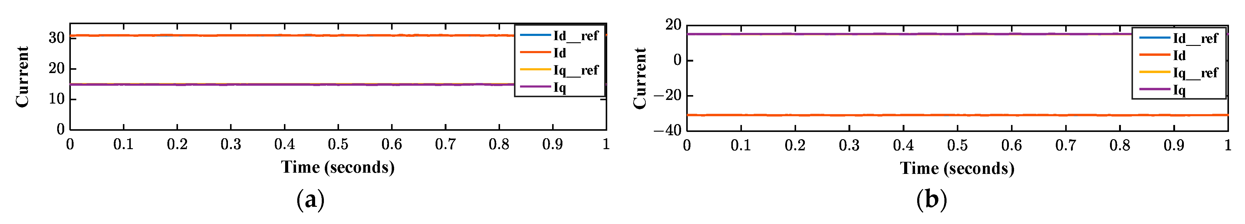
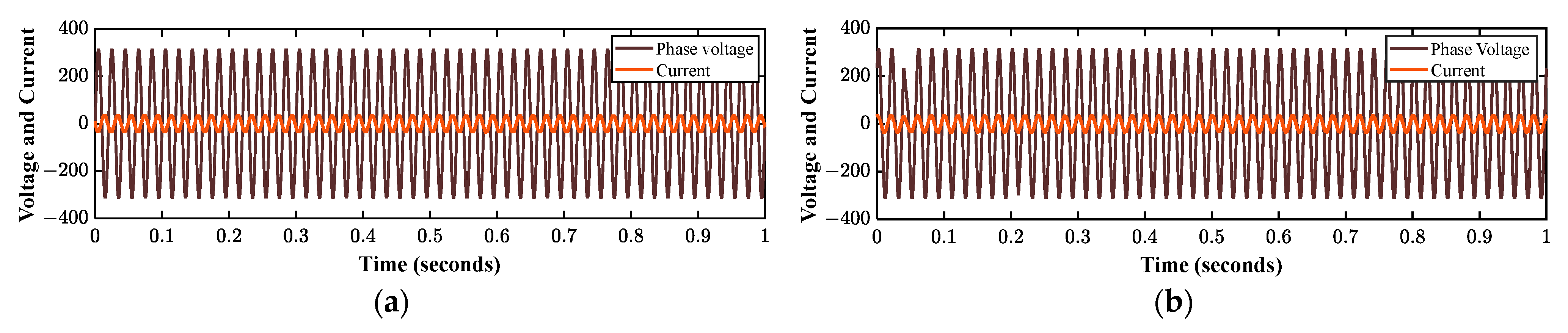
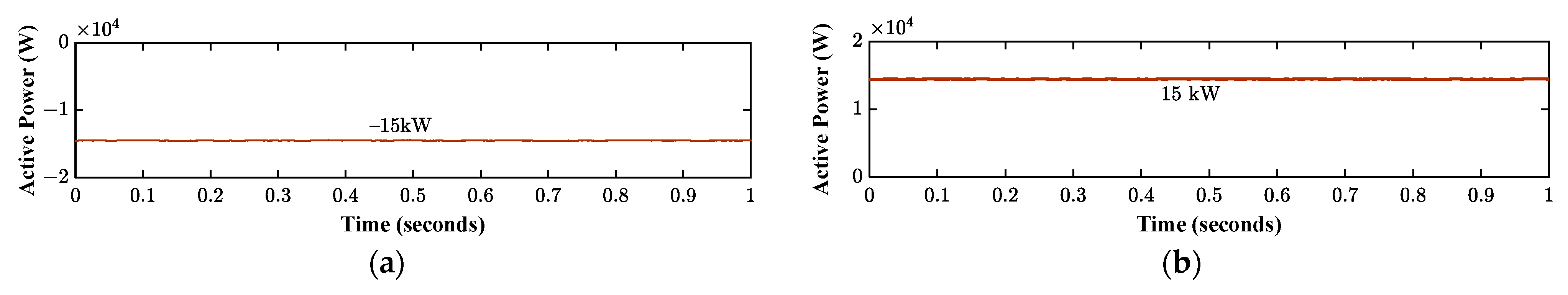
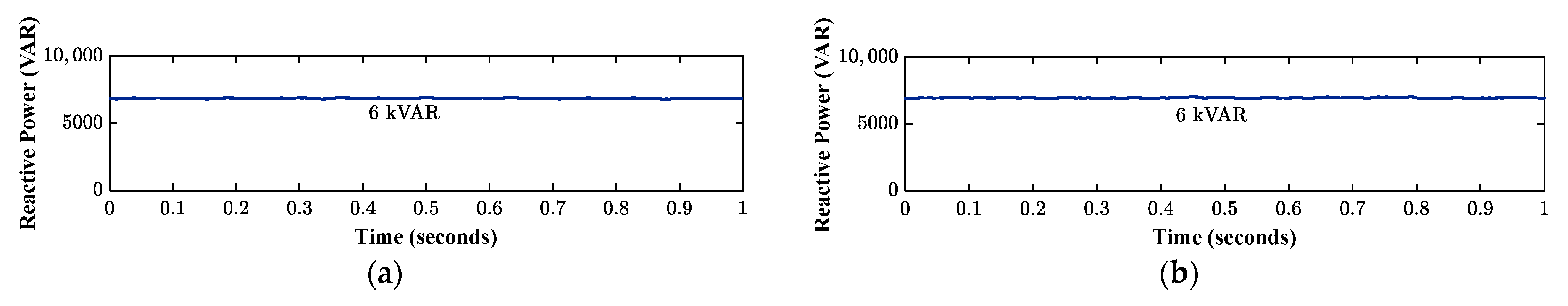
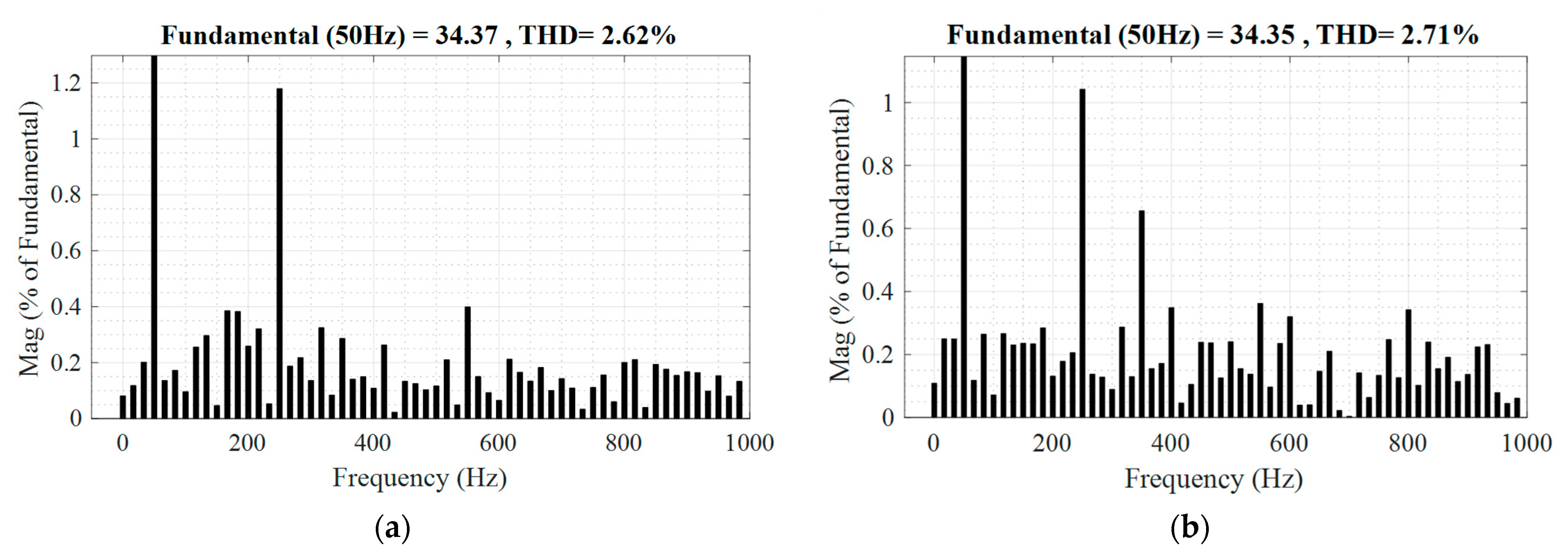
The recommended AD-based ICCL controller was implemented in discrete form, and its performance in both rectifier and inverter modes was examined with the help of a 16 kVA BADC system. The reference current generator in Equation (2) was used to set the reference current ( and ) in the VOC setup depicted in Figure 6 in accordance with the necessary power. When the reference current is positive, the VSC injects power into the grid, while when it is negative, the VSC is in rectifier mode. The controller performance in BPT is represented in Figure 17, Figure 18, Figure 19, Figure 20 and Figure 21. Figure 17 illustrates the reference currents of the converter in both modes of operation. The active reference current is 31 A in inverter mode and −31 A in rectifier mode. Reactive current references (15) are the same in both modes. Figure 18a shows that the phase voltage and current are out of phase when the VSC is operating in inverter mode. As seen in Figure 18b, the phase voltage and current in rectifier mode are in phase. According to Figure 19, the active power flow collected from RT simulation is around −15 kW (Figure 19a) and 15 kW (Figure 19b) in inverter and rectifier modes, respectively. Figure 20a,b illustrates the reactive power flow (6 kVAR) in the inverter and rectifier modes. Since the LCL filter absorbs the ripples in the switching current, the grid current waveforms are almost sinusoidal. The primary measure used to estimate power quality performance is the grid current’s THD, and according to IEEE standards, the permissible limit for THD is less than 5%. Figure 21a,b shows that the THDs in inverter and rectifier modes, respectively, are 2.62% and 2.71%. Both grid current modes’ THD complied with the IEEE standard. Figure 21a,b illustrates how the proposed VOC offers greater high-frequency harmonic reduction.
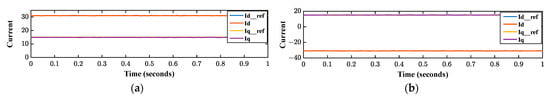
Figure 17.
Active and reactive current references: (a) uring inverter mode; (b) during rectifier mode.
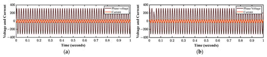
Figure 18.
Phase voltage and grid current: (a) during inverter mode; (b) during rectifier mode.
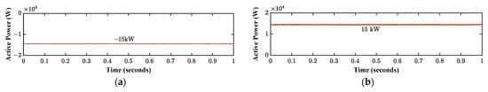
Figure 19.
Active power: (a) during inverter mode; (b) during rectifier mode.
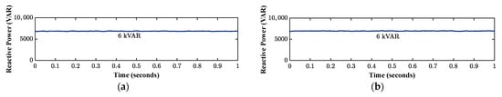
Figure 20.
Reactive power: (a) during inverter mode; (b) during rectifier mode.
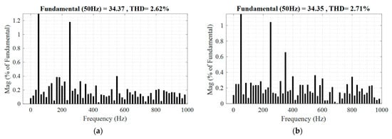
Figure 21.
Harmonic spectrum of grid current: (a) during inverter mode; (b) during rectifier mode.
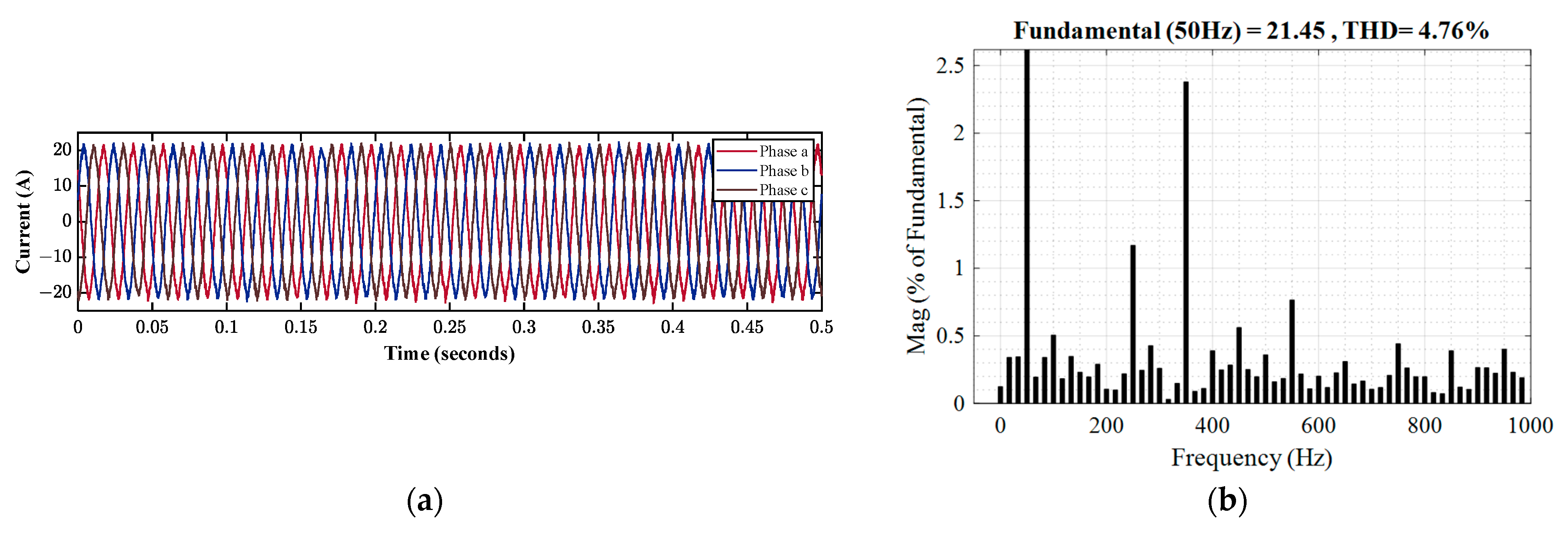
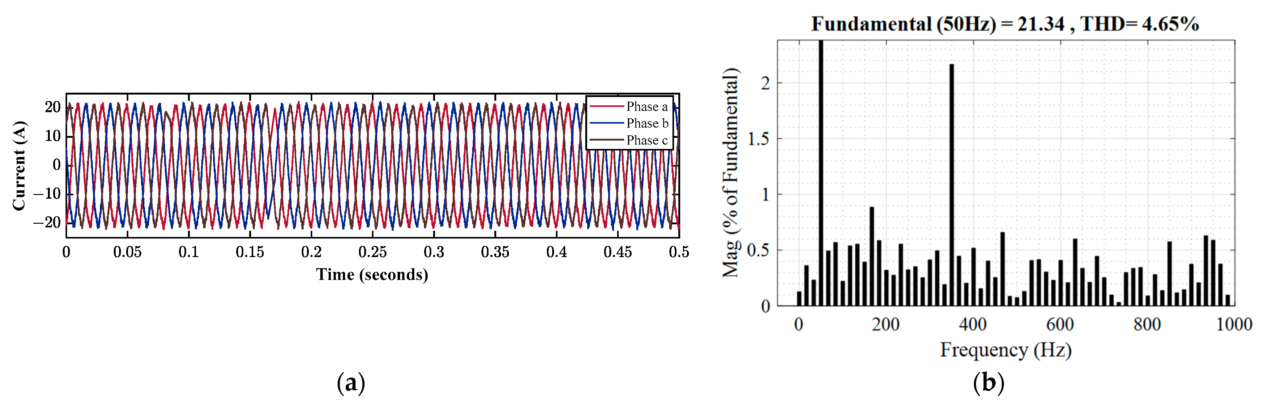
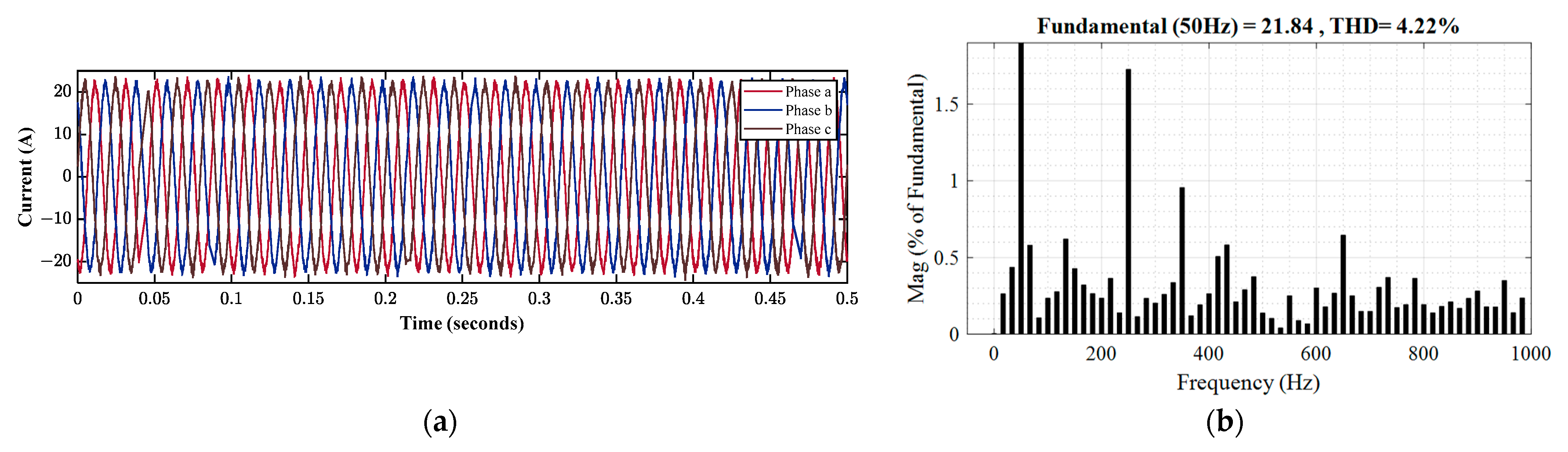
In this part, linear balanced and unbalanced loads with different power ratings are used to evaluate the performance of the controller. An 8 kW linearly balanced resistive, inductive (RL) load has been connected to the PCC to analyze the performance of the controller. Figure 22 displays the MG voltages at the PCC, with a magnitude of 311 volts under an 8 kW balanced load. The grid current quality under a traditional controller, a VOC scheme with direct CCF AD, and a proposed controller with observer-based CCF AD are shown in Figure 23, Figure 24 and Figure 25. The peak of the output grid current was reported as 20.34 A. Fast Fourier transform (FFT) analysis with a fundamental frequency of 50 Hz was used to get the THD result. The THD of the grid current is 4.76% under the traditional controller, as illustrated in Figure 23b, and 4.65% under the VOC system with direct CCF AD. As shown in Figure 25b, the suggested controller results in a 4.22% THD of grid current. Hence, as demonstrated by a comparison of Figure 23b, Figure 24b and Figure 25b, the suggested control system can provide a sinusoidal output current with a lower THD value of 4.22%.
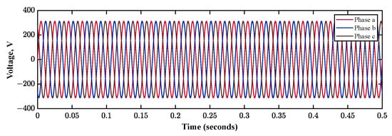
Figure 22.
Three-phase voltage at the PCC.
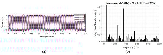
Figure 23.
Harmonics analysis of grid current for an 8 kW balanced load with traditional controller: (a) grid current; (b) harmonic spectrum.
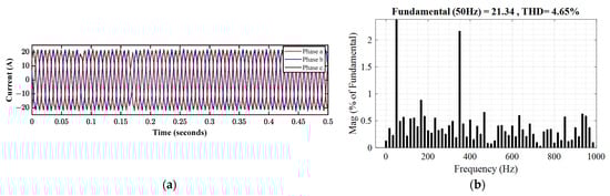
Figure 24.
Harmonics analysis of grid current for an 8 kW balanced load with a direct CCF AD: (a) grid current; (b) harmonic spectrum.
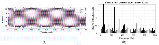
Figure 25.
Harmonics analysis of grid current for an 8 kW balanced load with proposed system: (a) grid current; (b) harmonic spectrum.
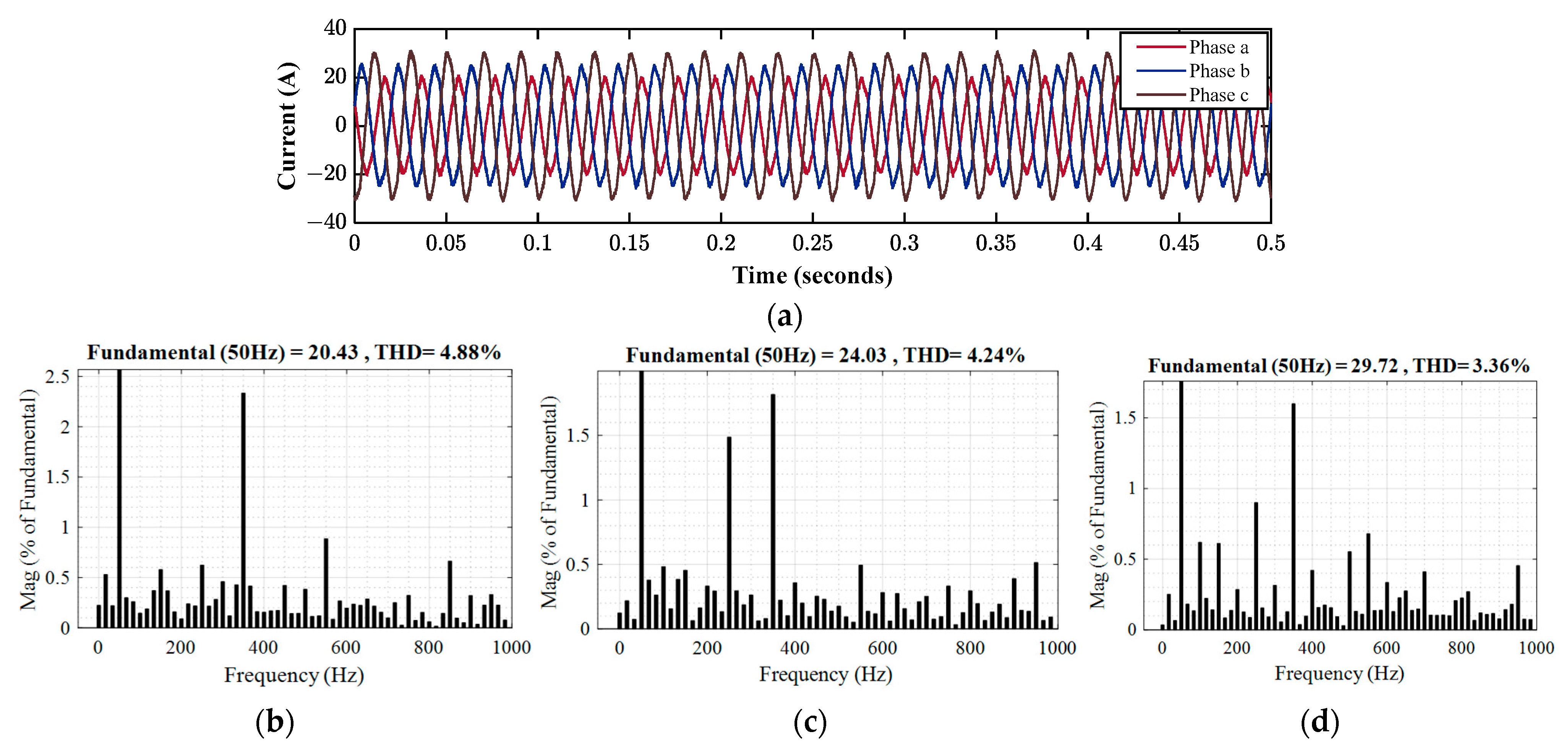
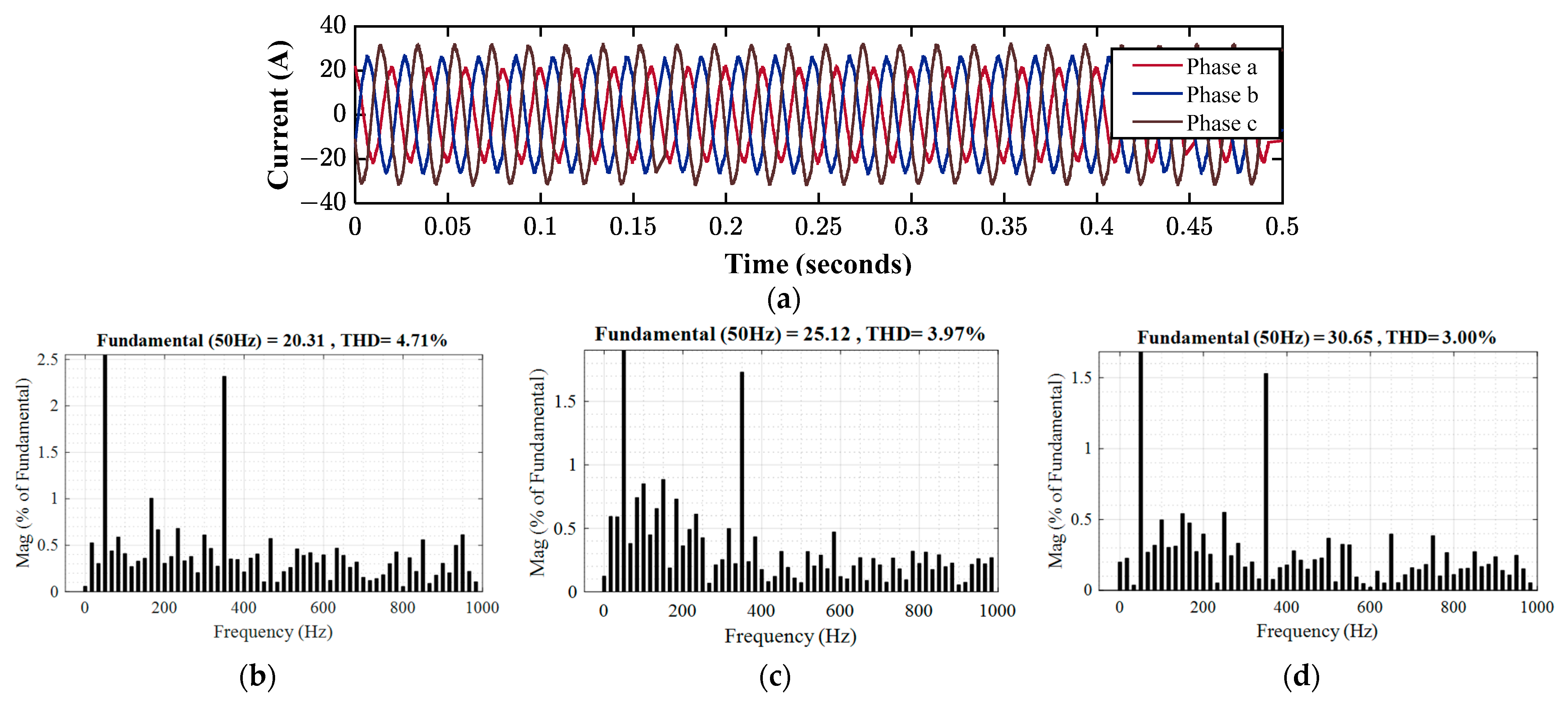
The harmonic spectra of the grid current under unbalanced conditions are displayed in Figure 26, Figure 27 and Figure 28 for a traditional controller, a VOC system with direct CCF AD, and a proposed controller with observer-based AD. For an unbalanced power load, the grid output current’s recorded THD varies due to unbalanced conditions. Figure 26 shows the performance of the traditional controller under an unbalanced load. The THD is 4.88% in Phase A, 4.24% in Phase B, and 3.36% in Phase C. Figure 27 shows the performance of the VOC scheme with direct CCF AD under an unbalanced load. The THD is 4.71% in Phase A, 3.97% in Phase B, and 3.00% in Phase C. Figure 28 shows that, in accordance with IEEE standards, the output currents obtained were sinusoidal in shape and had a THD value of less than 5% in case of the proposed control system.
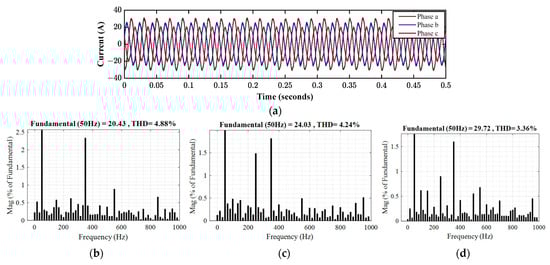
Figure 26.
Harmonics analysis of grid current for an unbalanced load with traditional controller: (a) grid current; (b) harmonic spectrum of Phase A; (c) harmonic spectrum of Phase B; and (d) harmonic spectrum of Phase C.
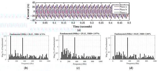
Figure 27.
Harmonics analysis of grid current for an unbalanced load with a direct CCF AD controller: (a) grid current; (b) harmonic spectrum of Phase A; (c) harmonic spectrum of Phase B; and (d) harmonic spectrum of Phase C.
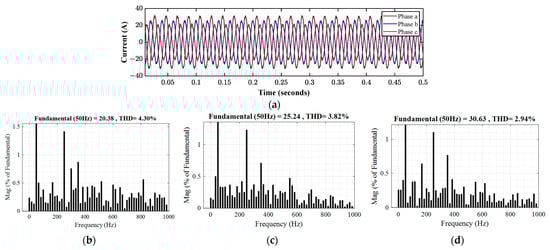
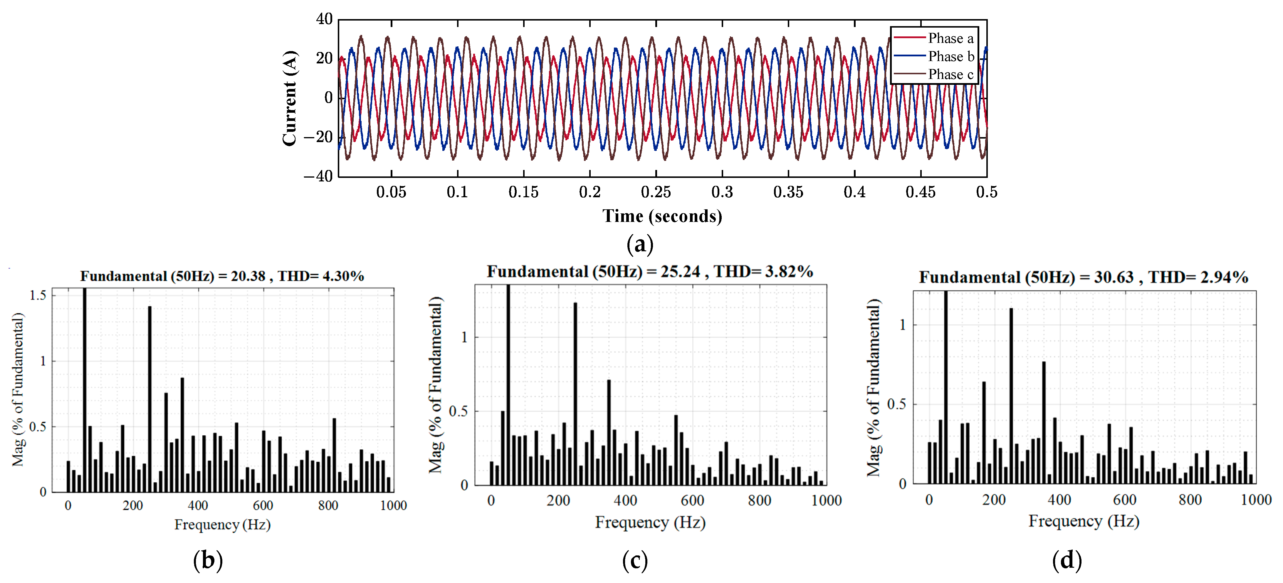
Figure 28.
Harmonics analysis of grid current for an unbalanced load with proposed system: (a) grid current; (b) harmonic spectrum of Phase A; (c) harmonic spectrum of Phase B; and (d) harmonic spectrum of Phase C.
The THD in Phase A and B are 4.30% and 3.82%, respectively. With 30.66 A of peak amplitude of grid current in Phase C, the grid output current’s THD is 2.94%.
The findings demonstrate that unbalanced loads do not affect the observer-based AD controller’s performance, and the VSC in inverter mode can export balanced three-phase currents to the main grid during unbalanced conditions.
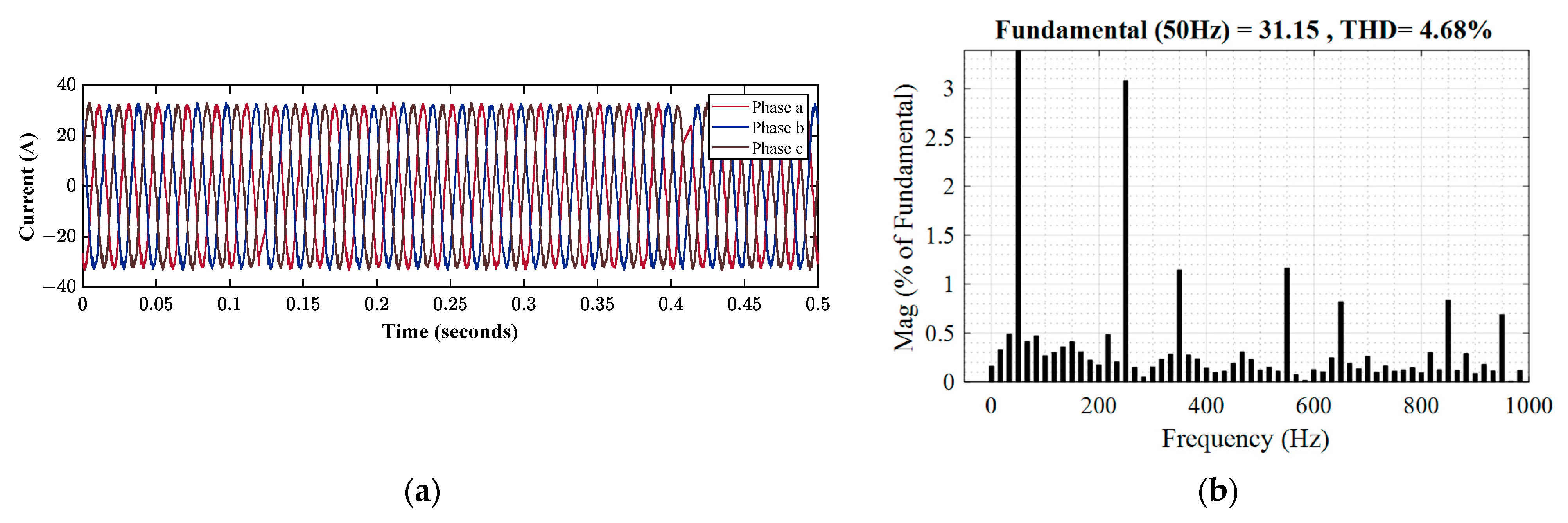
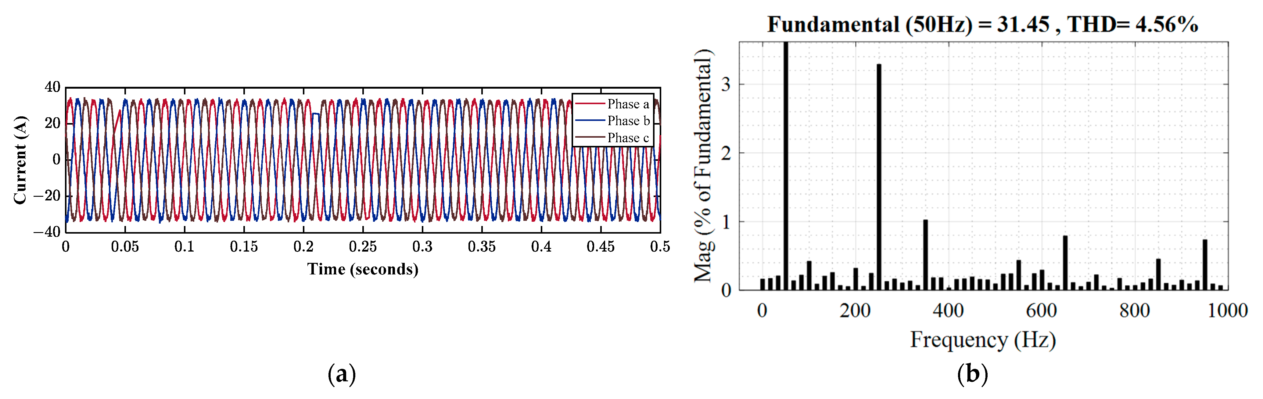
In this particular part, the performance of the controller is analyzed with a 2 kW nonlinear load. A three-phase nonlinear load consisting of a three-phase diode rectifier and a parallel RC load was considered to perform this analysis. The three-phase voltage at steady state after the system was linked to a non-linear local load. Figure 29, Figure 30 and Figure 31 depict the grid current simulation results for nonlinear loads using the three types of control systems. As observed in Figure 29, all of the phases’ output currents exhibited sinusoidal shapes with a peak amplitude of 30 A, but the THD is over 5%. The THD of the grid’s output current was 5.20% under the traditional controller. The THD of the grid’s output current was 4.68% under the VOC system with direct CCF AD. In contrast, as shown in Figure 31, the output current obtained for all phases had a sinusoidal shape, and the THD value was less than 5%. Figure 31b shows that under the assumed nonlinear load, the proposed control strategy was successful in keeping the THD of the output grid current at 4.56%. According to this analysis, the performance of the suggested controller is superior to that of the traditional controller because it can provide better grid current quality. So, when non-linear loads are applied to the system, the suggested controller benefits the grid-connected VSC system.
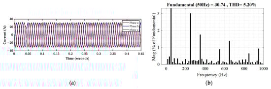
Figure 29.
Harmonics analysis of grid current for a nonlinear load with traditional controller: (a) grid current; (b) harmonic spectrum.

Figure 30.
Harmonics analysis of grid current for a nonlinear load with a direct CCF AD controller: (a) grid current; (b) harmonic spectrum.
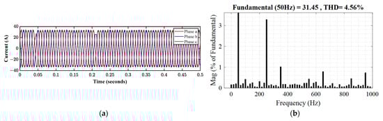
Figure 31.
Harmonics analysis of grid current for a nonlinear load with proposed control system: (a) grid current; (b) harmonic spectrum.
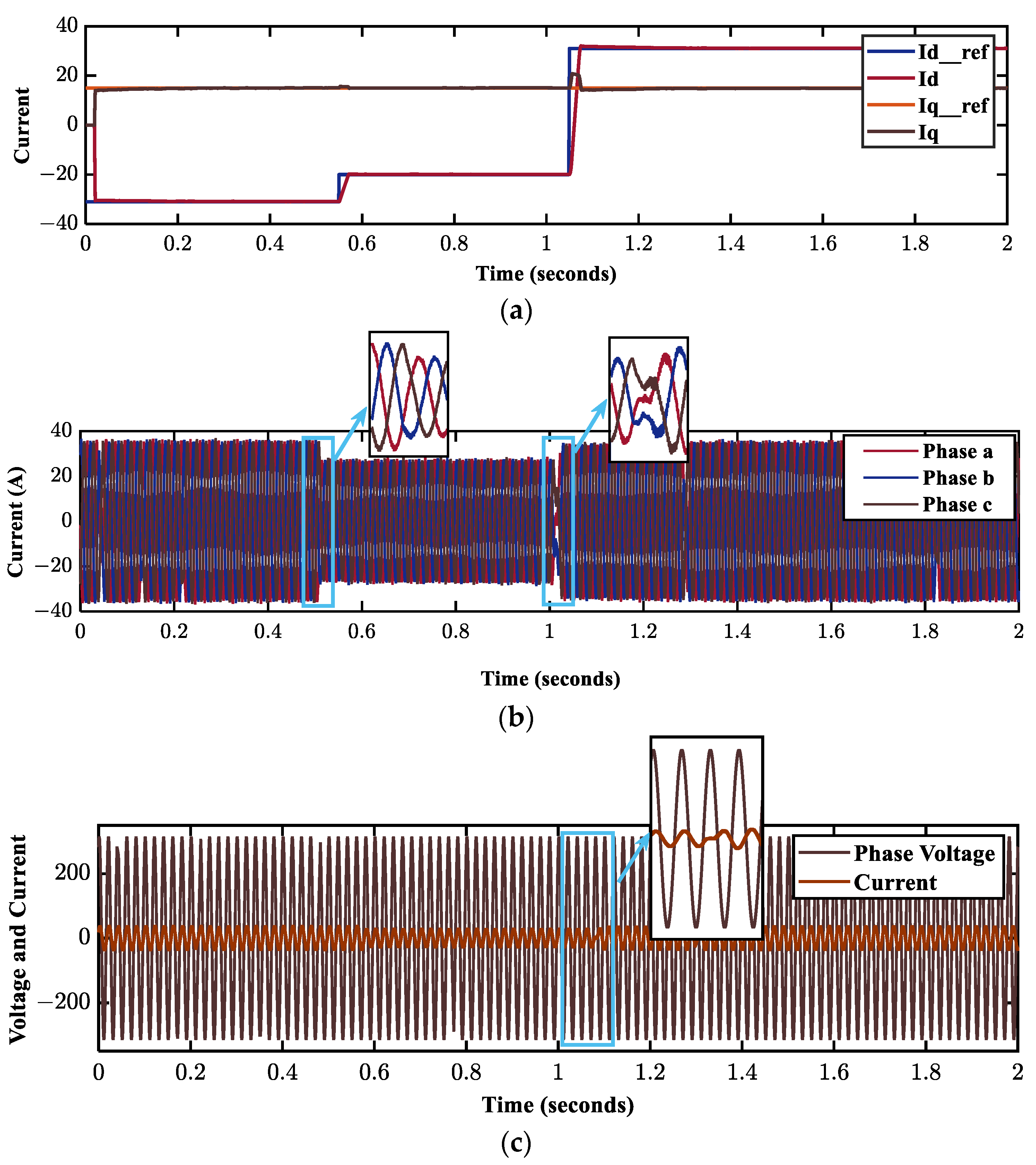
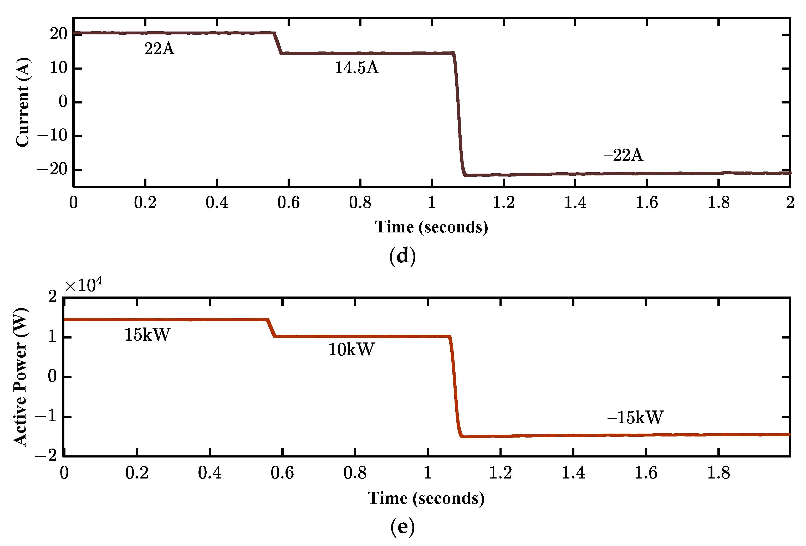
The dynamic response of the proposed ICCL-based VOC scheme is presented in Figure 32. Figure 32a illustrates the active and reactive current tracking performance of the controller. A step variation in the reference current () shown in Figure 32a of the ICCL causes the required changes in the reference current, grid current, DC-current, and active power. All the outcomes demonstrate that the suggested controller with observer-based AD is tracking the new reference with the lowest fluctuation. Figure 32a represents the required changes in the reference currents to perform the system’s dynamic performance analysis. Figure 32b shows that the grid-current traces the change from 34 A to 26 A at t = 0.55 s with the least fluctuation. At t = 1.05 s, the VSC alters the function from rectifier to inverter as the active current reference is further altered from negative (−22 A) to positive (31 A). At this moment, the grid-current changes from 26 A to 34 A and reverses its phase, shown in Figure 32b, to maintain the required power flow. In Figure 32b, the phase voltage and current remain in phase until t = 1.05 s, which represents the configuration working in rectifier mode. At t = 1.05 s, the grid-current reverses its phase to represent that the mode of operation of the model has changed from mode rectifier to inverter mode. The transition from rectifier to inverter mode requires less time and involves low distortion. In Figure 32c,d, the DC-current and active power of the BADC from t = 0 s to 1.05 s are positive, representing power flowing from the DC bus to the AC loads. At t = 0.55 s, both the DC-current and active power are reduced to 14.5 A and 10 kW, respectively, due to the step change in the reference current. Active power (−15 kW) and DC-current (−22 A) changes at t = 1.05 s due to the inverter’s mode of operation shown in Figure 32c,d.
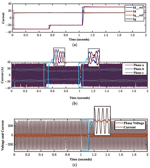
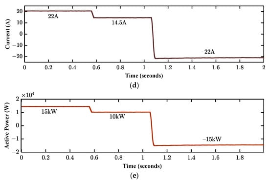
Figure 32.
Dynamic response of the proposed VOC-based BADC: (a) active and reactive current reference tracking; (b) grid-side current; (c) phase voltage and current; (d) DC-side current; (e) active power.
5.3. Comparative Analysis
This section compares the suggested VOC technique with observer-based AD to some previously introduced control strategies such as MPC, DPC, and VOC with different types of damping methods. For a fair comparison, the sampling frequency is kept at 10 kHz for all the controllers. Grid current harmonics in the inverter mode of operation were examined to assess the effectiveness of the suggested control strategy. Table 2 shows the results of the comparison analysis among various controllers based on the harmonic content of the current (THD). It is evident that the proposed VOC approaches with observer-based AD in this work produce superior outcomes than some earlier research in this field that has been published, i.e., the recommended offers lower harmonic contents in grid-current. Moreover, the proposed controller reduces the power loss of the BADC system by eliminating the damping resistor in the LCL filter.
Table 2.
A comparison of some previously introduced controllers with the proposed control system.
6. Conclusions
In order to guarantee BPT, improve grid current quality, and reduce power losses due to passive damping, this study provides a VOC-based improved current controller for an LCL-filtered 3P3L BADC system. The current controller employed a Luenberger Observer-based AD using CCF to reduce the resonance effect of the LCL filter on the system performance and stability. Due to the practical limitation of the current sensor and difficulties in capacitor current measurement, the observer is used to estimate the capacitor current from capacitor voltage. The performance of the proposed controller is analyzed for both linear balanced or unbalanced loads and nonlinear loads in terms of power quality. To verify the performance of the controller, the model’s configuration is built and simulated in RT using MATLAB/Simulink and the OPAL-RT platform (OP5600). Results from RT simulations showed that by using the suggested current controller, THD of grid-current is 4.22% for an 8 kW linearly balanced load, 4.30%, 3.82%, and 2.94% for an unbalanced load, and 4.56% for a 2 kW nonlinear load. The stability analysis from the Bode plot of the proposed controller shows that the LCL-filtered BADC system ensures stable operation via capacitor current feedback in the ICCL controller and reduces the additional power loss due to the damping resistor. Moreover, the suggested current controller offers excellent steady-state performance in both rectifier and inverter modes and a very quick dynamic response when the current reference changes. Hence, according to RT simulation findings, the converter system runs effectively enough for AC and hybrid MG frameworks to provide BPT with reduced voltage ripple, high efficiency, power loss, and lower THD. Advanced PLL and PWM approaches, along with proper tuning of the PI controller, can improve the performance of the suggested work even further.
Author Contributions
Conceptualization, methodology, and simulation, M.N.T., T.A., S.M.F. and M.A.D.; formal analysis, T.A., S.A., G.M.S. and S.M.; manuscript writing and editing, M.N.T., T.A., M.A.D., S.A., G.M.S., S.M.F. and S.M. All authors have read and agreed to the published version of the manuscript.
Funding
This research received no external funding.
Data Availability Statement
Data can be generated within this study.
Acknowledgments
The authors thank the Chittagong University of Engineering and Technology (CUET) for providing support under the Development of the CUET Project and Project No. CUET/DRE/2021-22/EEE/016 under Directorate of Research and Extension (DRE), CUET.
Conflicts of Interest
The authors declare no conflict of interest.
Nomenclature
| 3P3L | Three-phase three-leg |
| AD | Active damping |
| BADC | Bidirectional AC–DC converter |
| BPCs | Bidirectional power converters |
| BPT | Bidirectional power transfer |
| CCF | Capacitor current feedback |
| CVF | Capacitor voltage feedback |
| DPC | Direct power control |
| dq | Direct-quadrature |
| ESSs | Energy storage schemes |
| FFT | Fast Fourier transform |
| FOC | Field-oriented control |
| ICCL | Inner current control loop |
| LPF | low-pass filter |
| MG | Microgrid |
| MPC | Model predictive control |
| PCC | Point of common coupling |
| PE | Power electronics |
| PF | Power factor |
| PI | Proportional–integral |
| PLL | Phase lock loop |
| PV | Photovoltaic |
| Q | Quality factor |
| RESs | Renewable energy sources |
| RL | Resistive inductive |
| RT | Real-time |
| RT-SIL | Real-time software in-the-loop |
| SPWM | Sinusoidal pulse-width modulation |
| SRF | Synchronous reference frame |
| SVPWM | Space vector pulse-width modulation |
| THD | Total harmonic distortion |
| VOC | Voltage-oriented control |
| VSC | Voltage source converter |
| and | Equivalent series resistances of L1 and L2 |
| x | State vector |
| P | Rated power |
| Cf | Filter capacitor |
| C | DC-link capacitor |
| L1 and L2 | VSC- and Grid-side inductor |
| Ts | Sampling period |
| and | Reference active and reactive components |
| Td | Controller delay |
| VDC | DC-link voltage |
| fr | Resonance frequency |
| kp and ki | Proportional and integral gains |
| f | Grid frequency |
| A, B, C | System Matrix |
| u | System’s input matrix |
| Vc | Filter capacitor voltage |
| k | Proportional gain |
| Qg | Reactive power |
| and | Grid voltage in dq-frame |
| Vph(rms) | Rated RMS voltage |
| Vi | VSC voltage |
| L | Observer feedback gain |
| GLCL(s) | Transfer function of LCL filter |
| Grid Voltage | |
| ωr | Angular resonance frequency |
| C | DC-link capacitor |
| fsw | Switching frequency |
| ig | Grid-side current |
| ic | Capacitor current |
| ii | VSC-side currents |
| Pg | Active power |
| Estimated capacitor current | |
| Id and Iq | Grid current in -frame |
References
- Reza, M.S.; Hossain, M.M. Enhanced grid synchronization technique based on frequency detector for three-phase systems. IEEE Trans. Ind. Inform. 2021, 18, 2180–2191. [Google Scholar] [CrossRef]
- Hannan, M.; Wali, S.; Ker, P.; Rahman, M.A.; Mansor, M.; Ramachandaramurthy, V.; Muttaqi, K.; Mahlia, T.; Dong, Z. Battery energy-storage system: A review of technologies, optimization objectives, constraints, approaches, and outstanding issues. J. Energy Storage 2021, 42, 103023. [Google Scholar] [CrossRef]
- Hoummadi, M.A.; Bouderbala, M.; Aroussi, H.A.; Bossoufi, B.; El Ouanjli, N.; Karim, M. Survey of Sustainable Energy Sources for Microgrid Energy Management: A Review. Energies 2023, 16, 3077. [Google Scholar] [CrossRef]
- Muhtadi, A.; Pandit, D.; Nguyen, N.; Mitra, J. Distributed energy resources based microgrid: Review of architecture, control, and reliability. IEEE Trans. Ind. Appl. 2021, 57, 2223–2235. [Google Scholar] [CrossRef]
- Yang, P.; Xia, Y.; Yu, M.; Wei, W.; Peng, Y. A decentralized coordination control method for parallel bidirectional power converters in a hybrid AC–DC microgrid. IEEE Trans. Ind. Electron. 2017, 65, 6217–6228. [Google Scholar] [CrossRef]
- Pourbehzadi, M.; Niknam, T.; Aghaei, J.; Mokryani, G.; Shafie-khah, M.; Catalão, J.P. Optimal operation of hybrid AC/DC microgrids under uncertainty of renewable energy resources: A comprehensive review. Int. J. Electr. Power Energy Syst. 2019, 109, 139–159. [Google Scholar] [CrossRef]
- Patnaik, B.; Mishra, M.; Bansal, R.C.; Jena, R.K. AC microgrid protection—A review: Current and future prospective. Appl. Energy 2020, 271, 115210. [Google Scholar] [CrossRef]
- Rumky, T.J.; Ahmed, T.; Ahmed, M.; Mekhilef, S. Tri-Band Damping Controller for Low Frequency Oscillations in AC Microgrid System. In Proceedings of the 2023 IEEE IAS Global Conference on Renewable Energy and Hydrogen Technologies (GlobConHT), Male, Maldives, 11–12 March 2023; IEEE: New York, NY, USA, 2023; pp. 1–6. [Google Scholar]
- Al-Ismail, F.S. DC microgrid planning, operation, and control: A comprehensive review. IEEE Access 2021, 9, 36154–36172. [Google Scholar] [CrossRef]
- Kaur, A.; Kaushal, J.; Basak, P. A review on microgrid central controller. Renew. Sustain. Energy Rev. 2016, 55, 338–345. [Google Scholar] [CrossRef]
- Mbungu, N.T.; Naidoo, R.M.; Bansal, R.C.; Vahidinasab, V. Overview of the optimal smart energy coordination for microgrid applications. IEEE Access 2019, 7, 163063–163084. [Google Scholar] [CrossRef]
- Tasnim, M.N.; Ahmed, T.; Ahmad, S.; Mekhilef, S. Hardware in The Loop Implementation of The Control Strategies for the AC-Microgrid in OPAL-RT Simulator. In Proceedings of the 2023 IEEE IAS Global Conference on Renewable Energy and Hydrogen Technologies (GlobConHT), Male, Maldives, 11–12 March 2023; IEEE: New York, NY, USA, 2023; pp. 1–6. [Google Scholar]
- Sandelic, M.; Peyghami, S.; Sangwongwanich, A.; Blaabjerg, F. Reliability aspects in microgrid design and planning: Status and power electronics-induced challenges. Renew. Sustain. Energy Rev. 2022, 159, 112127. [Google Scholar] [CrossRef]
- Paul, S.; Sharma, A.; Padhy, N.P. Risk constrained energy efficient optimal operation of a converter governed AC/DC hybrid distribution network with distributed energy resources and volt-VAR controlling devices. IEEE Trans. Ind. Appl. 2021, 57, 4263–4277. [Google Scholar] [CrossRef]
- Ahmed, M.; Meegahapola, L.; Vahidnia, A.; Datta, M. Stability and control aspects of microgrid architectures—A comprehensive review. IEEE Access 2020, 8, 144730–144766. [Google Scholar] [CrossRef]
- Xia, Y.; Wei, W.; Yu, M.; Wang, X.; Peng, Y. Power management for a hybrid AC/DC microgrid with multiple subgrids. IEEE Trans. Power Electron. 2017, 33, 3520–3533. [Google Scholar] [CrossRef]
- Azeem, O.; Ali, M.; Abbas, G.; Uzair, M.; Qahmash, A.; Algarni, A.; Hussain, M.R. A comprehensive review on integration challenges, optimization techniques and control strategies of hybrid AC/DC Microgrid. Appl. Sci. 2021, 11, 6242. [Google Scholar] [CrossRef]
- Nejabatkhah, F.; Li, Y.W.; Tian, H. Power quality control of smart hybrid AC/DC microgrids: An overview. IEEE Access 2019, 7, 52295–52318. [Google Scholar] [CrossRef]
- Xiao, H.; Luo, A.; Shuai, Z.; Jin, G.; Huang, Y. An improved control method for multiple bidirectional power converters in hybrid AC/DC microgrid. IEEE Trans. Smart Grid 2015, 7, 340–347. [Google Scholar] [CrossRef]
- Ma, R.; Qiu, Q.; Kurths, J.; Zhan, M. Fast-slow-scale interaction induced parallel resonance and its suppression in voltage source converters. IEEE Access 2021, 9, 90126–90141. [Google Scholar] [CrossRef]
- Golestan, S.; Guerrero, J.M.; Al-Turki, Y.; Vasquez, J.C.; Abusorrah, A.M. Impedance modeling of three-phase grid-connected voltage source converters with frequency-locked-loop-based synchronization algorithms. IEEE Trans. Power Electron. 2021, 37, 4511–4525. [Google Scholar] [CrossRef]
- Razali, A.M.; Rahman, M.; George, G.; Rahim, N.A. Analysis and design of new switching lookup table for virtual flux direct power control of grid-connected three-phase PWM AC–DC converter. IEEE Trans. Ind. Appl. 2014, 51, 1189–1200. [Google Scholar] [CrossRef]
- Sahoo, B.; Routray, S.K.; Rout, P.K.; Alhaider, M.M. Power quality and stability assessment of hybrid microgrid and electric vehicle through a novel transformation technique. Sustain. Energy Technol. Assess. 2022, 51, 101927. [Google Scholar] [CrossRef]
- Michalec, Ł.; Jasiński, M.; Sikorski, T.; Leonowicz, Z.; Jasiński, Ł.; Suresh, V. Impact of Harmonic Currents of Nonlinear Loads on Power Quality of a Low Voltage Network—Review and Case Study. Energies 2021, 14, 3665. [Google Scholar] [CrossRef]
- Nour, M.; Chaves-Ávila, J.P.; Magdy, G.; Sánchez-Miralles, Á. Review of positive and negative impacts of electric vehicles charging on electric power systems. Energies 2020, 13, 4675. [Google Scholar] [CrossRef]
- Tlili, F.; Kadri, A.; Bacha, F. Advanced control strategy for bidirectional three phase AC/DC converter. Electr. Power Syst. Res. 2020, 179, 106078. [Google Scholar] [CrossRef]
- Ahmad, S.; Mubarak, H.; Jhuma, U.K.; Ahmed, T.; Mekhilef, S.; Mokhlis, H. Point of Common Coupling Voltage Modulated Direct Power Control of Grid-Tied Photovoltaic Inverter for AC Microgrid Application. Int. Trans. Electr. Energy Syst. 2023, 2023, 3641907. [Google Scholar] [CrossRef]
- Tiwari, R.; Kumar, K.; Babu, N.R.; Prabhu, K. Coordinated mppt and dpc strategies for pmsg based grid connected wind energy conversion system. Energy Procedia 2018, 145, 339–344. [Google Scholar] [CrossRef]
- Gui, Y.; Blaabjerg, F.; Wang, X.; Bendtsen, J.D.; Yang, D.; Stoustrup, J. Improved DC-link voltage regulation strategy for grid-connected converters. IEEE Trans. Ind. Electron. 2020, 68, 4977–4987. [Google Scholar] [CrossRef]
- Ali, S.U.; Aamir, M.; Jafri, A.R.; Subramaniam, U.; Haroon, F.; Waqar, A.; Yaseen, M. Model predictive control—Based distributed control algorithm for bidirectional interlinking converter in hybrid microgrids. Int. Trans. Electr. Energy Syst. 2021, 31, e12817. [Google Scholar] [CrossRef]
- Garcia-Torres, F.; Zafra-Cabeza, A.; Silva, C.; Grieu, S.; Darure, T.; Estanqueiro, A. Model predictive control for microgrid functionalities: Review and future challenges. Energies 2021, 14, 1296. [Google Scholar] [CrossRef]
- Xiao, D.; Alam, K.S.; Norambuena, M.; Rahman, M.F.; Rodriguez, J. Modified modulated model predictive control strategy for a grid-connected converter. IEEE Trans. Ind. Electron. 2020, 68, 575–585. [Google Scholar] [CrossRef]
- Golestan, S.; Ebrahimzadeh, E.; Wen, B.; Guerrero, J.M.; Vasquez, J.C. dq-frame impedance modeling of three-phase grid-tied voltage source converters equipped with advanced PLLs. IEEE Trans. Power Electron. 2020, 36, 3524–3539. [Google Scholar] [CrossRef]
- Reznik, A.; Simões, M.G.; Al-Durra, A.; Muyeen, S. $ LCL $ filter design and performance analysis for grid-interconnected systems. IEEE Trans. Ind. Appl. 2013, 50, 1225–1232. [Google Scholar] [CrossRef]
- Ahmed, M.; Abdelrahem, M.; Farhan, A.; Harbi, I.; Kennel, R. DC-link sensorless control strategy for grid-connected PV systems. Electr. Eng. 2021, 103, 2345–2355. [Google Scholar] [CrossRef]
- Cittanti, D.; Mandrile, F.; Gregorio, M.; Bojoi, R. Design space optimization of a three-phase LCL filter for electric vehicle ultra-fast battery charging. Energies 2021, 14, 1303. [Google Scholar] [CrossRef]
- Gurrola-Corral, C.; Segundo, J.; Esparza, M.; Cruz, R. Optimal LCL-filter design method for grid-connected renewable energy sources. Int. J. Electr. Power Energy Syst. 2020, 120, 105998. [Google Scholar] [CrossRef]
- Miskovic, V.; Blasko, V.; Jahns, T.M.; Smith, A.H.; Romenesko, C. Observer-based active damping of $ LCL $ resonance in grid-connected voltage source converters. IEEE Trans. Ind. Appl. 2014, 50, 3977–3985. [Google Scholar] [CrossRef]
- Büyük, M.; Tan, A.; Tümay, M.; Bayındır, K.Ç. Topologies, generalized designs, passive and active damping methods of switching ripple filters for voltage source inverter: A comprehensive review. Renew. Sustain. Energy Rev. 2016, 62, 46–69. [Google Scholar] [CrossRef]
- Yao, Z.; Xiao, L.; Guerrero, J.M. Improved control strategy for the three-phase grid-connected inverter. IET Renew. Power Gener. 2015, 9, 587–592. [Google Scholar] [CrossRef]
- Trinh, Q.-N.; Choo, F.H.; Wang, P. Control strategy to eliminate impact of voltage measurement errors on grid current performance of three-phase grid-connected inverters. IEEE Trans. Ind. Electron. 2017, 64, 7508–7519. [Google Scholar] [CrossRef]
- Zhang, H.; Xian, J.; Shi, J.; Wu, S.; Ma, Z. High performance decoupling current control by linear extended state observer for three-phase grid-connected inverter with an LCL filter. IEEE Access 2020, 8, 13119–13127. [Google Scholar] [CrossRef]
- Srita, S.; Somkun, S.; Kaewchum, T.; Rakwichian, W.; Zacharias, P.; Kamnarn, U.; Thongpron, J.; Amorndechaphon, D.; Phattanasak, M. Modeling, simulation and development of grid-connected voltage source converter with selective harmonic mitigation: Hil and experimental validations. Energies 2022, 15, 2535. [Google Scholar] [CrossRef]
- Xin, Z.; Loh, P.C.; Wang, X.; Blaabjerg, F.; Tang, Y. Highly accurate derivatives for LCL-filtered grid converter with capacitor voltage active damping. IEEE Trans. Power Electron. 2015, 31, 3612–3625. [Google Scholar] [CrossRef]
- Samanes, J.; Urtasun, A.; Gubia, E.; Petri, A. Robust multisampled capacitor voltage active damping for grid-connected power converters. Int. J. Electr. Power Energy Syst. 2019, 105, 741–752. [Google Scholar] [CrossRef]
- Pan, D.; Ruan, X.; Bao, C.; Li, W.; Wang, X. Capacitor-current-feedback active damping with reduced computation delay for improving robustness of LCL-type grid-connected inverter. IEEE Trans. Power Electron. 2013, 29, 3414–3427. [Google Scholar] [CrossRef]
- Geng, Y.; Song, X.; Zhang, X.; Yang, K.; Liu, H. Stability analysis and key parameters design for grid-connected current-source inverter with capacitor-voltage feedback active damping. IEEE Trans. Power Electron. 2020, 36, 7097–7111. [Google Scholar] [CrossRef]
- Wang, X.; He, Y.; Pan, D.; Zhang, H.; Ma, Y.; Ruan, X. Passivity enhancement for LCL-filtered inverter with grid current control and capacitor current active damping. IEEE Trans. Power Electron. 2021, 37, 3801–3812. [Google Scholar] [CrossRef]
- Li, S.; Lin, H. A capacitor-current-feedback positive active damping control strategy for LCL-type grid-connected inverter to achieve high robustness. IEEE Trans. Power Electron. 2021, 37, 6462–6474. [Google Scholar] [CrossRef]
- Zhang, H.; Wang, X.; He, Y.; Pan, D.; Ruan, X. A compensation method to eliminate the impact of time delay on capacitor-current active damping. IEEE Trans. Ind. Electron. 2021, 69, 7512–7516. [Google Scholar] [CrossRef]
- Jain, B.; Jain, S.; Nema, R. Control strategies of grid interfaced wind energy conversion system: An overview. Renew. Sustain. Energy Rev. 2015, 47, 983–996. [Google Scholar] [CrossRef]
- Kim, S.-H. Electric Motor Control: DC, AC, and BLDC Motors; Elsevier: Amsterdam, The Netherlands, 2017. [Google Scholar]
- Jiang, Y.; Li, Y.; Tian, Y.; Wang, L. Phase-locked loop research of grid-connected inverter based on impedance analysis. Energies 2018, 11, 3077. [Google Scholar] [CrossRef]
- Dai, Z.; Li, G.; Fan, M.; Huang, J.; Yang, Y.; Hang, W. Global stability analysis for synchronous reference frame phase-locked loops. IEEE Trans. Ind. Electron. 2021, 69, 10182–10191. [Google Scholar] [CrossRef]
- Kim, S.-H. Pulse width modulation inverters. Electr. Mot. Control 2017, 17, 265–340. [Google Scholar]
- Wang, X.; Li, Y.W.; Blaabjerg, F.; Loh, P.C. Virtual-impedance-based control for voltage-source and current-source converters. IEEE Trans. Power Electron. 2014, 30, 7019–7037. [Google Scholar] [CrossRef]
- Liu, Z.; Liu, J.; Zhao, Y. A unified control strategy for three-phase inverter in distributed generation. IEEE Trans. Power Electron. 2013, 29, 1176–1191. [Google Scholar]
- Li, W.; Ruan, X.; Pan, D.; Wang, X. Full-feedforward schemes of grid voltages for a three-phase $ LCL $-type grid-connected inverter. IEEE Trans. Ind. Electron. 2012, 60, 2237–2250. [Google Scholar] [CrossRef]
- Dannehl, J.; Wessels, C.; Fuchs, F.W. Limitations of voltage-oriented PI current control of grid-connected PWM rectifiers with $ LCL $ filters. IEEE Trans. Ind. Electron. 2008, 56, 380–388. [Google Scholar] [CrossRef]
- Golestan, S.; Monfared, M.; Freijedo, F.D. Design-oriented study of advanced synchronous reference frame phase-locked loops. IEEE Trans. Power Electron. 2012, 28, 765–778. [Google Scholar] [CrossRef]
- Sun, Y.; de Jong, E.C.W.; Wang, X.; Yang, D.; Blaabjerg, F.; Cuk, V.; Cobben, J.F.G. The impact of PLL dynamics on the low inertia power grid: A case study of Bonaire Island power system. Energies 2019, 12, 1259. [Google Scholar] [CrossRef]
- Errouissi, R.; Shareef, H.; Awwad, F. Disturbance observer-based control for three-phase grid-tied inverter with LCL filter. IEEE Trans. Ind. Appl. 2021, 57, 5411–5424. [Google Scholar] [CrossRef]
- Saleem, M.; Choi, K.-Y.; Kim, R.-Y. Resonance damping for an LCL filter type grid-connected inverter with active disturbance rejection control under grid impedance uncertainty. Int. J. Electr. Power Energy Syst. 2019, 109, 444–454. [Google Scholar] [CrossRef]
- Saïd-Romdhane, M.B.; Naouar, M.W.; Slama-Belkhodja, I.; Monmasson, E. Robust active damping methods for LCL filter-based grid-connected converters. IEEE Trans. Power Electron. 2016, 32, 6739–6750. [Google Scholar] [CrossRef]
- Gao, T.; Lin, Y.; Chen, D.; Xiao, L. A novel active damping control based on grid-side current feedback for LCL-filter active power filter. Energy Rep. 2020, 6, 1318–1324. [Google Scholar] [CrossRef]
- Guan, Y.; Wang, Y.; Xie, Y.; Liang, Y.; Lin, A.; Wang, X. The dual-current control strategy of grid-connected inverter with LCL filter. IEEE Trans. Power Electron. 2018, 34, 5940–5952. [Google Scholar] [CrossRef]
- Gui, Y.; Wang, X.; Blaabjerg, F. Vector current control derived from direct power control for grid-connected inverters. IEEE Trans. Power Electron. 2018, 34, 9224–9235. [Google Scholar] [CrossRef]
- Nam, N.N.; Nguyen, N.D.; Yoon, C.; Choi, M.; Lee, Y.I. Voltage sensorless model predictive control for a grid-connected inverter with LCL filter. IEEE Trans. Ind. Electron. 2021, 69, 740–751. [Google Scholar] [CrossRef]


Disclaimer/Publisher’s Note: The statements, opinions and data contained in all publications are solely those of the individual author(s) and contributor(s) and not of MDPI and/or the editor(s). MDPI and/or the editor(s) disclaim responsibility for any injury to people or property resulting from any ideas, methods, instructions or products referred to in the content. |
© 2023 by the authors. Licensee MDPI, Basel, Switzerland. This article is an open access article distributed under the terms and conditions of the Creative Commons Attribution (CC BY) license (https://creativecommons.org/licenses/by/4.0/).