Abstract
Over the past few years, there have been significant advancements in Microgrid (MG) systems, particularly in the field of power electronics. These advancements aim to address the needs of the grid and loads, while integrating low-voltage, non-linear, and highly sensitive power sources, such as solar PV modules, batteries, and supercapacitors. It is crucial to select the appropriate converter configuration and power converters in MG systems, as they greatly impact their optimal performance. To achieve the best results, numerous architectures and converter configurations have been suggested for integrating different energy sources. As a result, a considerable number of research articles have been published, necessitating a thorough review. This article continues studies of Part I and presents a comprehensive overview of various architectures based on the arrangement of different sources and provides a detailed analysis and discussion of these architectures. This article covers thirty-three different categories of DC-DC converters, both isolated and non-isolated. These converters are divided into subcategories, such as conventional type, switched-capacitor type, soft-switching type, multi-phase type, and multilevel type. The article also evaluates the suitability of these topologies based on factors such as high conversion gain, power decoupling, efficiency, isolation, power handling capabilities, and compact design. The critical examination and comparative study presented in this work can be valuable for industry professionals and academics in selecting the most suitable architectural and power converter topologies for optimal performance.
1. Introduction
Remote societies in various countries, like India, China, or Russia, are often isolated from the main power grid due to decentralization and low population density. As a result, achieving electrification through the main grid in these areas is challenging due to financial constraints and available resources. To overcome these limitations, researchers have proposed an alternative solution known as an autonomous distributed power system. Such systems utilize sustainable energy sources, like solar PV, solar thermal energy, wind energy, hydro, biomass, geothermal, ocean waves, and tidal energy, along with storage technologies, such as batteries, supercapacitors, and fuel cells. Advancements in power converter technologies have facilitated the development of this autonomous system. Among the renewable energy technologies, solar PV has gained popularity due to its ease of installation, advanced technology, low operational costs, and modular nature. PV systems typically provide electricity to meet the basic needs of residential customers, including lighting, refrigeration, and other essential electrical appliances. These PV systems can be implemented in two ways: on-grid systems, which are connected to the main grid, and off-grid systems, which operate independently.
The primary objective of this study is to supplement studies [1] (Part I) to bridge the existing gap in the literature by providing a comprehensive review and analysis of potential architectures, power management schemes, and power converter topologies for the electrification of remote areas. The aim of Part II is to present a classification of bidirectional DC-DC converter (BDC) topologies, both isolated and non-isolated, which can assist in selecting the most suitable BDC structure for a specific hybrid energy storage system (HESS) configuration. The ultimate goal of this investigation is to facilitate the implementation of HESS in remote autonomous PV system applications, thus reducing the financial burden on local residents. This can be achieved by adopting the appropriate architecture, converters, and other components to enhance battery life, reliability, compactness, safety, and efficiency, among other objectives.
The remainder of Part II is structured as follows. Section 2 deals with converter topologies for solar-powered HESS; various BDC topologies, along with their classifications, control, and switching strategies, are discussed. For a clear understanding, the layout of every category is explained as their subsections. Finally, Section 3 discusses the overall comparison of the topologies and HESS configurations for the selection of an optimal topology for the specified application.
2. Converter Topologies for Solar-Powered HESS
2.1. Topology Classifications of BDCs
BDCs are classified into isolated and non-isolated structures. In non-isolated topologies, no magnetic isolation is used while transferring the power from the source to load. Due to the absence of a transformer in non-isolated configurations, benefits due to galvanic isolation, like a huge step-up voltage gain ratio, will not be offered. However, they can offer benefits of easy setup and avoid the drawbacks of galvanic isolation, like magnetic interference and more weight. These features are critical; the primary objective is to achieve the size and weight matter. On the other hand, in the isolated topologies, the input DC voltage is inverted to high-frequency AC voltage, which is fed to a high-frequency transformer for voltage level change and then converted to DC. In general, the voltage gain is more in isolated topologies than in non-isolated topologies. However, in these converters, the modeling process of the transformer and the reduction of leakage inductance are the most significant factors. The subsequent sections analyze these converters in the topology perspective and present them in detail.
2.1.1. Non-Isolated Topologies
In general, the non-isolated BDC is implemented by connecting a diode and controllable switch in antiparallel fashion with the switch and diode of the unidirectional converter, respectively (if there is no prior insertion). Apart from the classical DC-DC converter structures, such as buck, boost, buck–boost, Cuk, etc., a few more non-isolated topologies are discussed in this subsection. Some of the reviewed topologies emerged based on the concept of these basic topologies. On the other hand, some additional configurations are basically proposed in the literature on the basis of voltage-boosting, interleaving, multilevel, switched-capacitor, etc. concepts. The reviewed non-isolated topologies are categorized into eight groups, as presented below.
Conventional Topologies
- (a)
- Non-Isolated Buck and Boost-derived BDC [2]
As shown in Figure 1, the basic BDC is implemented by using the concept of the buck and boost converter. The improvement in the buck and boost converter has truly realized this bidirectional structure. In other words, if the basic buck and boost converter’s unidirectional switches are replaced with bidirectional power switches, a bidirectional buck–boost converter can be created. When converting voltage from low level to high level, this converter operates in boost mode, and from high level to low level in buck mode.
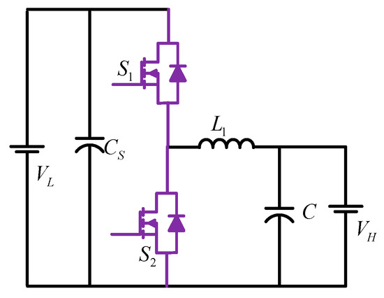
Figure 1.
Non-Isolated Buck and Boost-derived BDC.
- (b)
- Non-Isolated Buck–Boost-derived BDC [3]
A bidirectional buck–boost converter can be attained from a conventional unidirectional buck–boost converter in a similar method as discussed above, i.e., replacing the unidirectional switches with bidirectional power switches, as shown in Figure 2. The basic buck–boost converter has the capability to buck or boost the voltage level, and the same feature can be obtained with the bidirectional buck–boost converter with the opposite output voltage polarity for bidirectional power flow applications.
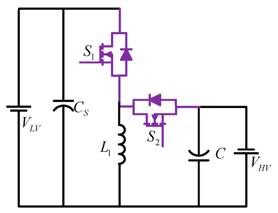
Figure 2.
Non-Isolated Buck–Boost-derived BDC.
- (c)
- Non-Isolated Cuk-derived BDC [4,5,6]
The known characteristics of the continuous input and output current of the Cuk converter can be transformed into a bidirectional topology (as shown in Figure 3) by replacing a unidirectional switch and diodes with bidirectional power switches. In the literature, with the variations of this topology, some topology based on the Cuk concept has been presented. The unidirectional converter with a coupled-inductor configuration was introduced to suppress the ripples of input/output currents [5]. This strategy applied to the bidirectional Cuk converter, and it was investigated the performance of the bidirectional coupled-inductor Cuk converter [6].
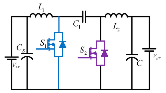
Figure 3.
Non-Isolated Cuk-derived BDC.
- (d)
- Non-Isolated SEPIC and ZETA-derived BDC [7,8]
Another DC-DC converter is created by rearranging the Cuk converter components and applying SEPIC Converter [7] and Zeta converter [8] principles to obtain a positive output voltage. Figure 4 depicts the developed bidirectional SEPIC/Zeta converter. This setup acts as a SEPIC converter when power is flowing from VL to VH terminals and as a Zeta converter when power is flowing in the other direction. The supplementary branch used in this converter can suppress current ripples, while also providing a new method of supplying power directly [8].
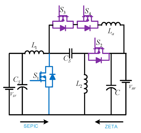
Figure 4.
Non-Isolated SEPIC and ZETA-derived BDC.
Bridge Topologies
- (e)
- Cascaded BDC [9,10]
A simple cascaded non-isolated BDC is formed by connecting two buck–boost BDCs in a cascaded form, as illustrated in Figure 5. This formation enhances the voltage gain capability and decreases the current stress on the load-side converter. Due to the high gain feature, this converter can be adopted for EV applications with low-voltage-rated ES elements. Though there is a need for excess elements, with respect to the conventional bidirectional buck–boost converter, this structure has the advantage of a greater voltage gain ratio with the same switch duty cycle. In addition to this, the current stresses and current ripples are significantly decreased. Hence, it can handle more power ratings. An auxiliary capacitor (Ca) can be included in the converter to decrease the output current ripples.
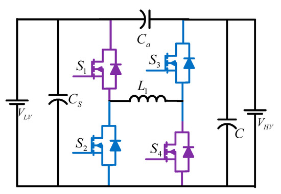
Figure 5.
Cascaded BDC.
- (f)
- Switched-Capacitor BDC [11]
There is another concept in the literature called the switched-capacitor (SC) cell, utilized for enhancing the voltage boosting ability of the converter. The bidirectional converter with a switched-capacitor cell, as shown in Figure 6, is used to improve the voltage gain. This new derived converter is obtained by transforming the unidirectional SC cell arrangement into a bidirectional SC cell arrangement [12]. In this SC configuration, as no inductor is used, the magnetic interference and weight are greatly reduced. However, the converter may possess continuous input current, even in the absence of an input inductor, by adopting a parallel connection between two identical strings, which are made up of cells. This parallel connection with two SC cells should operate in opposite phase to have a continuous input current.
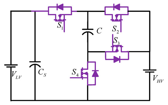
Figure 6.
Switched-Capacitor BDC.
Soft-Switching Topologies
- (g)
- Fully soft-switched Buck and Boost BDC [13,14]
In many BDC applications, the soft-switching scheme is essential to increase the converter efficiency. Figure 7 shows a soft-switching buck and boost BDC [13], which comprises two main switches, S1 and S2; one auxiliary switch, Sa; three resonant components, Lr1, Lr2, and Cr; four diodes, DS1, DS2, DSa1, and Dr; and one filter inductor, Lf. In comparison with similar kinds of soft-switching topologies, the complexity of this converter is less. In this structure, the soft-switching action in both the buck and the boost modes is achieved by the auxiliary switch and resonant elements. So, the effective power transfer during buck and boost modes can be achieved. In each switching period, the auxiliary switch operates only once. Here, the filter inductor is considered as large enough to produce constant load current.

Figure 7.
Fully soft-switched buck and boost BDC.
Multi-Phase Topologies
- (h)
- Interleaved BDC [15,16,17,18]
The interleaving strategy used in the BDC, as shown in Figure 8, significantly decreases the current ripples caused due to the switching frequency. Hence, it needs only a smaller EMI filter. In the automotive industry, an interleaved bidirectional converter with multiple stages has proven that it decreases the size of the filter and thermal management and improves dynamic performance [14]. There are different structures in the interleaved topologies, for example, a few interleaved bidirectional topologies suggested in [15,16]. In those papers, some topologies were realized with the various fashions of inductor coupling, such as direct or reverse, to decrease the current ripples and enhance the converter’s dynamic performance.
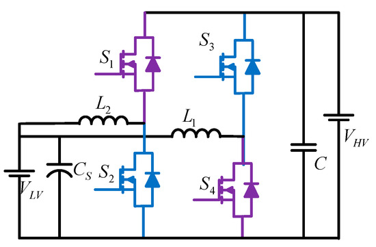
Figure 8.
Interleaved BDC.
- (i)
- Four-phase IBDC with TCIs [19,20]
The multi-phase interleaved concept in BDCs is becoming very popular due to the capability of the current stress reduction on the switches and enhancing the converter’s dynamic response. In many applications, the interleaved and magnetically integrated BDCs are extensively used. At present, all the phase inductors in these converters are integrated, usually to one single-core coupled inductor. However, it has some consequences, while increasing the phase number for high-power applications, such as the asymmetry of magnetic elements, increased design complexity of multi-phase cores, more DC flux, etc. Therefore, multi-phase interleaved BDC (IBDC) with two-winding coupled inductors (TCIs) is introduced to overcome these problems.
In the conventional IBDC, there will be a considerable increment in the inductor number during the increment in the interleaved phases. So, this will increase the cost, weight, and volume. Further, it is not possible to achieve better transient and steady-state responses, hence, a converter proposed four-phase IBDC with a novel connection method, as shown in Figure 9 [19]. It is not only limited for four-phases, but also, there is a possibility to extend it for 2N-phase IBDC. The presented converter has a significant improvement in the transient and steady-state responses when compared to the conventional IBDC.

Figure 9.
Four-phase IBDC with TCIs.
Multilevel Topologies
- (j)
- FC–Multilevel non-isolated BDC [21]
The circuit illustrated in Figure 10 represents a multilevel BDC. In this circuit, each level has a switching module, which is utilized as a repeating pattern to offer high voltage gain. In dual-voltage automotive systems, multilevel BDC can be employed. The weight and size of the converter are significantly decreased since there are no magnetic elements.
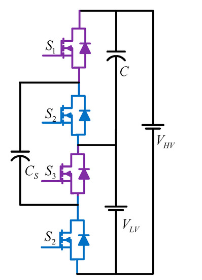
Figure 10.
Multilevel non-isolated BDC.
For the application of dual voltage (42/14 Volt) automotive systems, an efficient, compact, and magnetic-less BDC is reported, as shown in Figure 11 [21]. This topology utilizes a flying capacitor (FC)-based four-level BDC, which comprises six switching cells and three switching poles. Due to the typical multilevel converter configuration, this DC-DC converter offers several advantages, such as the capability of accommodating various voltage levels of the battery, less EMI (electromagnetic interference), and low price due to utilizing low-voltage MOSFETs.

Figure 11.
Multilevel (4L) FC-based non-isolated BDC.
In this topology, the authors used only a constant duty cycle instead of using PWM strategies. It works the same as a voltage multiplier. This topology does not demand any magnetic elements for its realization. But, this kind of topology has various drawbacks, such as too much voltage drop across the switches, a comparatively difficult switching scheme, non-modular design, a hard-switching issue, the complex control of bidirectional power flow, etc.
- (k)
- Multilevel cascaded DC-DC converter topology [22]
Similar to multilevel and cascaded DC-DC converters, the multilevel cascaded DC-DC converter is becoming a more interesting research area, specifically, for PV-powered applications [22,23,24,25]. In the traditional PV system, in general, both the buck and boost configurations are utilized in cascaded topology. Here, in Figure 12, the buck-natured converter utilized for the design of a cascaded DC-DC converter applied in PV systems is shown [22]. In the buck topology, the active device configuration guarantees to continue its operation during the fault state. It is caused due to the diversion of the current path by the freewheeling diode during the failure of the PV module. Among the three types of multilevel converters (MLCs), such as diode-clamped (DC), flying-capacitor (FC), and cascaded H-bridge (CHB) converters, the DCMLC is not widely used for the DC-DC applications, because it has the least number of redundant switching states. On the other hand, the FCMLCs are widely considered for several DC applications, due to their advantages, such as simple construction and adaptable voltage balancing characteristics caused by more redundant switching states [26]. Moreover, the usage of fewer devices is an attractive feature in this topology. Several favorable features of the CHB topology, such as more redundant switching states, minimum voltage stress, compact design, and simple switching strategy, are attracting researchers to use this topology in various applications. Hence, this topology is a prominent candidate for the DC-DC medium- and high-power applications.

Figure 12.
Multilevel cascaded DC/DC converter.
- (l)
- 5L-MMCCC with four modular blocks [26,27]
Due to highly modular structure, the modular multilevel converter (MMC) is gaining a lot of attention and becoming the primary fascinating multilevel converter configuration for high- and medium-power applications [26], specifically, for HVDC systems based on the voltage source converter (VSC). Figure 13 shows a five-level, multilevel, modular, capacitor-clamped DC/DC converter (5L-MMCCC) [27]. This specific design was built to attain a significantly high voltage conversion ratio. Every modular block contains a single capacitor and three transistors and three conducting terminals.
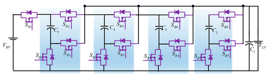
Figure 13.
Five-level MMCCC with four modular blocks.
Due to the advantages of this converter, such as high power-sharing capacity, modular design, bidirectional power flow capacity, and onboard fault bypassing, it can be preferred instead of some traditional switched-capacitor converters. The circuit acquires redundancy due to the greater modularity of this configuration, and also reliability is greatly enhanced. Additionally, the modular design provides the utilization of an extra level to bypass the fault and bidirectional power sharing. Hence, this converter can be the best possible option to provide a bidirectional power-sharing mechanism between the buses operating with distinct voltages.
2.1.2. Isolated Topologies
Isolated topologies use galvanic isolation, which is an optimistic method to obtain more voltage gain capability by including an extra degree of freedom, i.e., windings turn ratio, to the converter gain. It offers flexibility to use it in the systems where there is a need to operate for a wide range of input voltages and load regulation [28]. Apart from high voltage gain, this isolation offers additional advantages, like the chance of the easy implementation of multi-input or multi-output configurations, and provides the isolation between both the source and the load sides in the case of critical loads. Hence, these converters are suitable in the solar-powered microgrid systems where there are loads highly sensitive to noise and faults, and hence, safety is the biggest issue.
Conventional Topologies
- (a)
- Isolated Buck–Boost BDC (Bidirectional Flyback) [29]
To obtain more voltage gain from a buck–boost converter, several approaches are presented in the absence of isolation [30]. However, in the magnetic isolation case, the Flyback converter is analyzed by substituting a transformer for the buck–boost converter’s inductor. A bidirectional isolated buck–boost converter, as depicted in Figure 14, can be realized using the bidirectional evolution approach and the non-isolated concept. The gain of the converter is achieved in forward power transfer by implementing the charge-second and volt-second balance concept, which is equivalent to the voltage gain of the Flyback converter. That should be noted. When designing a transformer for flyback operation, the voltage snubber used on the primary side must be considered to reduce transformer leakage current. Additional improvements to this topology have been made in the literature to improve the voltage gain even more [31].

Figure 14.
Bidirectional Flyback.
- (b)
- Push–Pull BDC [28,32]
A bidirectional push–pull converter (Figure 15) is proposed based on a unidirectional push–pull converter to allow bidirectional power flow. Similar to unidirectional push–pull converters, these bidirectional push–pull converters use a multi-winding transformer to transfer power from the source to the load. The study in [32] proposes a three-phase bidirectional push–pull converter to improve the power-handling capability for high-power applications.
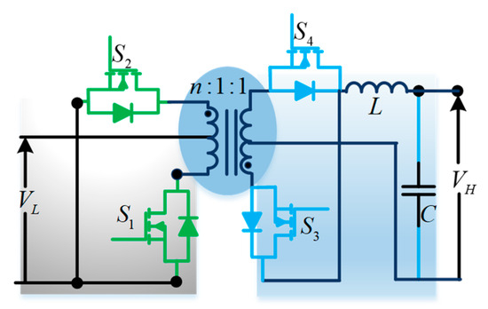
Figure 15.
Push–Pull BDC.
- (c)
- Forward BDC [33,34,35,36,37]
As shown in Figure 16, in consideration of the unidirectional forward converter, the bidirectional forward converter could be recommended. To achieve zero-voltage switching, a clamped circuit can be employed in this converter. In [34], the investigation on the bidirectional forward DC-DC converter is proposed as a resonant version by utilizing the leakage inductance of the transformer utilized as a resonant inductor. Depending on the required load demands and characteristics, various combinations of previously mentioned topologies, such as Push–Pull–Forward [35], Flyback–Push–Pull [36], and Forward–Flyback [37], are proposed as hybrid setups. The transformer’s primary side in these converters can be derived from any one of the discussed isolated topologies, and the secondary side is from either voltage-fed or current-fed.
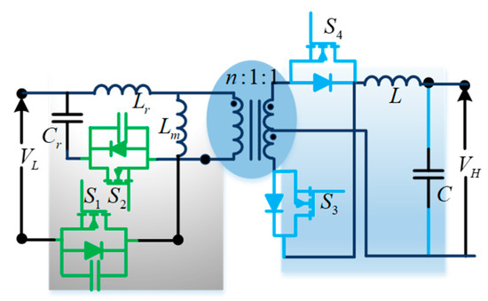
Figure 16.
Forward BDC.
- (d)
- Isolated CUK & SEPIC/ZETA BDC [29,38,39]
To attain the advantages of magnetic isolation, an isolated bidirectional Cuk converter is implemented on the basis of the original edition of the non-isolated bidirectional Cuk converter. This topology is illustrated in Figure 17 and has continuous input and output current, and the isolation feature. The isolation transformer is provided between both the source and the load sides to attain the significantly high value of the voltage gain ratio, which also depends on the transformer turns ratio. As discussed earlier in (c), the cancellation of the output and input current ripples [40] is observed when there is coupling between the input and output inductor. This feature is more essential in RE systems. To attain an isolated form of the bidirectional SEPIC/Zeta converters [39], the same way can be followed.

Figure 17.
Isolated CUK & SEPIC/ZETA BDC.
Bridge Topologies
- (e)
- Single-Active Bridge (SAB) converter [41]
The functionalities of the power DC-DC converter in a DC wind farm are the same as those of a transformer in the traditional AC wind farm. Figure 18 depicts the single-active bridge (SAB) converter, which can be considered as a prospective topology to employ in DC wind farm applications, applied in a 5MW turbine [41]. The leakage inductance Ls in the SAB converter affects the output current and voltage. The converter operation yields a triangular current waveform in the transformer. But, due to the flaw of single-direction power flow, this converter is not widely considered in many DC power system applications. So, in order to avoid this problem, this SAB converter can be replaced with a triangle-current-mode dual-active bridge (DAB) converter [42,43], as explained below.

Figure 18.
SAB converter.
- (f)
- Dual-Active Bridge (DAB) BDC [43,44,45,46,47,48]
This topology is proposed by placing the isolated converter by a high-frequency transformer between the back-to-back fully active bidirectional topologies. This topology is one of the widely used topologies in an isolated configuration. These back-to-back converters are of different types and classified as voltage-fed, current-fed, half-bridge, and full-bridge dual-active converters. A simple DAB converter topology [44] is shown in Figure 19, where the transformer has two full-active bridge topologies on each side. In bidirectional converters, the transmission of power is equivalent to the number of switches [43]. This present topology consists of eight power switches, including galvanic isolation. This topology can be employed in high-power applications with the requirement of high voltage gain. But, it may suffer from more switching losses due to the usage of a greater number of switches in the converter. These losses incurred due to the involvement of more switches can be decreased to a certain level by replacing the Si-based power semiconductor switches with gallium nitride (GaN) or silicon carbide (SiC) switches. Additionally, the rate of energy transfer in the converter can be regulated by creating the phase shift between the primary and secondary windings of the transformer. An effective control strategy may possess efficiency optimization, which necessitates the investigation of the essentiality of suitable control strategies for this converter.
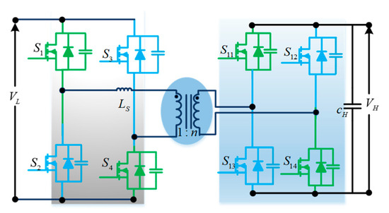
Figure 19.
DAB BDC.
As DAB configurations are one of the widely used isolated structures, detailed analyses are carried out by various researchers on these topologies. Detailed analysis is presented in [45]. The common structure of the obtained DAB converter is illustrated in Figure 20. In addition to the high-frequency transformer, a resonant tank can also be added to attain ZVS/ZCS, so that the DC-DC converter efficiency can be enhanced further [46,47,48]. A detailed analysis of the control strategies is reviewed in Section 3 and Section 4.

Figure 20.
The common structure of DAB.
- (g)
- Dual Half-Bridge BDC [49,50,51,52]
In half-bridge topologies, which can be sufficient for low-power applications when compared to full-bridge topologies, the number of switches is decreased to four instead of the eight in full-bridge topology. This bidirectional converter topology is depicted in Figure 21, where the transformer is configured with a voltage-fed half-bridge on each side [49,50]. The absence of the inductor in this topology results in the absence of zero in the right half-plane. As a result of the minimal phase behavior, the controller’s design complexity is minimized in the converters. The converter proposed in [51] is based on dual half-bridge topology, with the primary side of the transformer using current-fed half-bridge topology and the secondary side using voltage-fed topology. The other version of this topology is expected to be reversed, with the primary-side transformer using voltage-fed topology and the secondary side using current-fed half-bridge topology [52].

Figure 21.
Dual Half-Bridge BDC.
In some specific loads, where a need for continuous current is required, the current-fed topology may be used to fulfill this requirement. The interleaved half-bridge topology is proposed as an advanced study of Dual Half-Bridge converters to enhance the voltage rise ability and reduce the current stress and transformer turns ratio [53].
- (h)
- Half-Bridge–Full-Bridge BDC [54,55,56]
An isolated bidirectional converter in the UPS model is suggested in [54], with the consideration of DAB structure, where the primary side of the transformer uses a voltage-fed half-bridge module, and the secondary side utilizes a voltage-fed full-bridge module (Figure 22) [55]. The design of this control structure is easier than DAB because of it having a minimum number of switches. Hence, in order to obtain the entire UPS topology, this bidirectional converter is incorporated at the half-bridge side of a two-switch buck–boost converter.
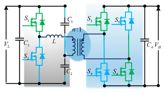
Figure 22.
Half-Bridge–Full-Bridge BDC.
There are some more advanced features added to this design to improve the performance of the system, like merging impedance networks with half-bridge and full-bridge topologies [56].
- (i)
- Multiport DAB BDC [57,58,59]
Multi-input converters can be used where the applications have multiple input sources, such as hybrid electric vehicles (HEVs) and sustainable energy systems [58]. With reference to DAB, an isolated multi-input BDC utilizes a multi-winding transformer, as reported in [57], with the inclusion of the decoupling nature of power flow, as shown in Figure 23. It is worth noticing that, in multiport converters, the power flow control and the control of duty cycle utilization are significant issues to optimize the system performance [59].
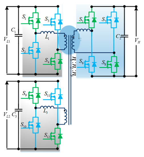
Figure 23.
Multiport DAB BDC.
Soft-Switching Topologies
- (j)
- Full-bridge series resonant converter [40]
During one or more sub-intervals of each switching period, the voltage and current of a resonant inductor and capacitor used in a resonant power converter to attain soft switching are sinusoidal in nature. Introducing more than one component of the LC circuit either in series or parallel to the full-bridge devices, the voltage appearing across the semiconductor devices can offer the conduction and commutation occurrence at zero-voltage points, called zero-voltage switching. Figure 24 shows a DC-DC series resonant converter. The DC link of the inverter is fed by the input voltage via the EMI filter. A step-down transformer having a turn’s ratio of n:1 is connected across the AC terminals of the inverter. Between the diode bridge rectifier and transformer, a resonant tank circuit comprising a capacitor and inductor is placed. While producing the required output voltage Vout, the capacitor minimizes the ripple content at the output terminals of the rectifier.
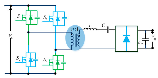
Figure 24.
Full-bridge series resonant converter.
In a series resonant converter, the output voltage is controlled by dividing the voltage between the resonant tank circuit and the AC resistance absorbing energy, such that the voltage across the equivalent AC resistance absorbing energy is maintained at a fixed value. In [40], the time domain analysis of the modulated phase shift, implemented full bridge for a series resonant converter is reported. In this topology, an adaptive resonant tank circuit is implemented to maintain ZVS over the entire operating range. The following advantages are obtained from the converter reported in [40].
Advantages:
- High operating switching frequency due to inherent low switching losses;
- Use of unavoidable parasitic capacitances included in the resonant tank;
- Low EMI levels;
- More power density;
- One capacitor is sufficient for the output filter;
- Inherent short-circuit protection because of resonant inductance connected in series with the load;
- Flat efficiency versus load.
- (k)
- LLC Resonant HB DC-DC Converter [60,61]:
In the case of isolated DC-AC-DC BDC structures, there exist more stages and, hence, occurred more losses. To enhance the performance of those kinds of systems, the soft-switching concept has to be implemented, as efficiency is a key factor. Many resonant configurations are created for MG applications.
Theoretically, the impedance of the resonant converters is regulated from zero to infinity by implementing frequency modulation control. This can be helpful for equating the source (PV module/Batteries/SCs) and load characteristics by excluding any extra series of parallel-connected resistors. Specifically, for solar applications, these resonant converters are more relevant than conventional PWM-based isolated DC-DC converters. Many resonant converters are designed for the solar PV applications, in which the series resonant converter (SRC) can provide enough efficiency. But, in light-load conditions, it faces the issue of output-voltage control. The parallel resonant converter (PRC) will help to solve this issue. But, due to the higher circulating energy in this converter greatly impacting efficiency, in order to obtain the advantages of both the converters (SRC and PRC), a series–parallel resonant converter (SPRC) is implemented. This is less sensitive to load changes and has lower circulating energy. However, these converters require being operated at a high switching frequency for the required voltage gain. During this condition, all the converters possess a high circulating current, resulting in low efficiency. Figure 25 shows the LLC resonant converter, introduced to solve the above-mentioned drawback. This converter has a lower minimum circulating energy than the former three converters; therefore, the MG system efficiency can be eventually improved. However, in this configuration, the input-side DC-HF AC inverter is of the half-bridge type, which results in considerable stress on the semiconductors compared to both sides’ full-bridge configurations.
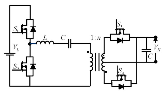
Figure 25.
LLC resonant Half-Bridge DC-DC Converter.
- (l)
- SPCD converter topology [62]
Below, Figure 26 depicts the series–parallel current-driven (SPCD) full-bridge DC-DC converter [62], which comprises a series branch containing Ls and shunt branches containing Lp and Cp. As per Figure 26, the voltage pulses are converted to current pulses by using this series branch inductor Ls, and the reactive current for ZVS is generated by the shunt branches Lp and Cp, and hence, implementation follows the current-driven converter design.

Figure 26.
SPCD converter topology.
The shunt branch parameters Ls and Lp can be easily inserted into the high-frequency transformer. Moreover, the extra circuit needed to attain ZVS can be avoided by this Lp. So, this SPCD full-bridge configuration gives an effective converter with a high power density. It is because this configuration can minimize parasitic elements of the transformer and utilize those elements for effective power transfer.
From Figure 26, it can be understood that the diodes at the output side become turned off when the current through Lp is equal to the Ls current. Hence, the energy stored in both the inductances Ls and Lp at that instant is utilized to discharge the output capacitance of the leading leg-switching devices (the resultant output capacitance is denoted as the equivalent capacitor at the output terminals of the MOSFETs containing their parasitic capacitance and the foreign snubber capacitors included to avoid the MOSFET turn-off losses).
In the above discussion, the output capacitor is discharged by the Ls and Lp; a little amount of current is needed to ensure ZVS. That is why the traditional full-bridge converter at light loads loses ZVS. However, the SPCD converters provide triangular currents, unlike the sinusoidal currents generated by the resonant topologies. This is the key disadvantage of this configuration.
- (m)
- Boost–full-bridge converter for bidirectional high-power application [63]
In the last few years, full-bridge DC-DC converters have been attaining importance when they are working with PWM ZVS [63,64,65,66]. For high-power applications, the isolated full-bridge converter is implemented, as depicted in Figure 27. In the system, the switching losses are minimized by implementing soft-switching strategies that lead to an increase in switching frequency [64]. Figure 27 shows an isolated-boost full-bridge converter for bidirectional power flow [63]. A popular soft-switching PWM full-bridge buck converter is also utilized for boost operation, like double operating fashion, in the suggested converter. During the commutation process, the discrepancy between currents of the leakage inductor and the boost inductor is reduced by enabling an unparalleled commutation process in the control scheme of this topology.

Figure 27.
Boost–FB converter for bidirectional high-power application.
In an isolated boost converter, when a current source inverter is energizing the transformer, then it causes high-voltage spikes across the devices in the high-frequency inverter due to transformers’ leakage inductance, which is the opposite to that of the isolated buck converter. For applications where the high-power bidirectional transfer is required, a dual-active full-bridge-based DC-DC converter is suggested. The transformer is energized by two voltage source inverters on both sides, excluding the current-fed inverter. The soft-switching condition is applied for both voltage source inverters.
- (n)
- Boost half-bridge and full-bridge [65]
In [65], an isolated DC-DC converter is proposed, as depicted in Figure 28. It has the capability of connecting two inputs, i.e., voltage-fed and current-fed ports are coupled by including boost full-bridge and half-bridge cells. Despite the dual-input configuration benefits, the limitation is uneven current stress on the switches, which enhances the complexity of the design. Moreover, asymmetrical functioning and the effect of the dead band are not considered in this analysis.
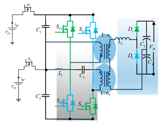
Figure 28.
Hybrid DC-DC converter.
The benefits of this converter are shown below.
Advantages
- Dual-input connectivity;
- Minimum number of switches and their corresponding gate driver elements;
- ZVS turn-on of the primary switches;
- ZCS turn-off of the diodes by eliminating the reverse recovery problem.
Two ports, namely, voltage-fed and current-fed ports, are used in the suggested converter for achieving greater flexibility with various power sources in real-time applications. The turn’s ratios of both the transformers T1 and T2 as n1:n2 are configured in a different way: the terminals of primary windings having dotted notation are connected at the same point, named as ‘A’, whereas the remaining secondary windings are connected in series (depending on the requirement they can be connected in parallel, too). On the secondary side, the voltage-doubler circuit is used, and the output capacitor C3 or C4 will naturally clamp the diodes voltage ringing. The sum of the leakage inductance and the additional inductance form L2. To prevent transformer overload induced by any asymmetrical action in the full-bridge topology, a DC-blocking capacitor (Cb) is inserted in series with the T2 primary winding.
- (o)
- Two-stage isolated BDC [67]
A two-stage isolated BDC with a suitable hybrid-switching scheme is shown in Figure 29 [68]. This topology has reduced the transformer size by adopting a high switching frequency. The resonant nature of this converter reduces the turn-off switching loss due to the tail current. The bidirectional control is taken care of by an additional PWM non-isolated converter placed near to the load. The MOSFET-aided hybrid-switching design reduces the severe turn-off switching losses that occurred due to a greater number of devices. The hybrid-switching scheme is employed to minimize the switching losses and eliminate the snubber circuitry. This results in more power density and more efficiency in the high-power/high-voltage applications. A loss study of this converter has been presented, and quantitative comparative analysis has been carried out with reference to voltage-fed full-bridge and current-fed full-bridge (VF − FB + CF − FB) bidirectional topologies to demonstrate the benefits of this topology.
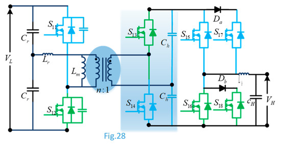
Figure 29.
Two-stage isolated BDC.
- (p)
- Triangular-current-mode dual-active bridge (TCM-DAB) [69,70,71,72]
The TCM-DAB DC-DC converter topology with regard to the internal-charge dynamic characteristics is reported for medium-voltage and high-power applications, as shown in Figure 30 [69]. In this configuration, the series inductor Ls is used in place of the resonant tank of the conventional series resonant full-bridge converter. The switches of the medium-voltage side can be operated in ZCS mode for bidirectional power flow applications, which is achieved by choosing a proper-turns ratio of the HF transformer and duty ratio of the LV-side switches [70,71]. But, the ZCS operation on the LV side, in this case, is not possible. Moreover, due to the circulation of more reactive power in the DAB converter causing huge current stresses, more losses limit this converter’s use in high-power applications [72].

Figure 30.
TCM-DAB converter.
Multi-Phase Topologies
- (q)
- High-voltage DC-DC full-bridge converter [66]
Figure 31 shows a high-voltage DC-DC converter, configured for capacitor charging power supply (CCPS) for pulsed-power application by dead time, which is taken into account [66]. It comprises a full-bridge phase-shifted PWM converter having three high-voltage, high-frequency transformers.
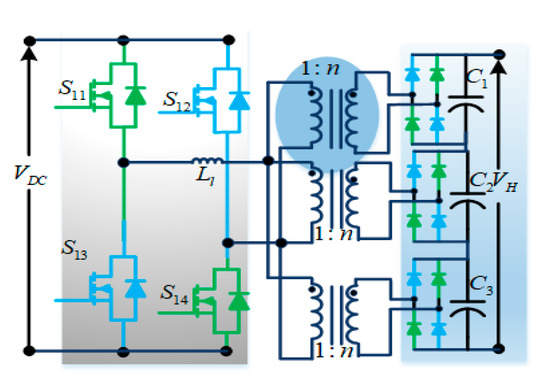
Figure 31.
HV DC-DC FB converter.
To fulfil the ZVS or ZCS condition, the phase-shifted PWM should be soft-switched [68]. This implies that the losses in the converter are suppressed, and hence, it can be utilized for high-power, high-frequency applications.
- (r)
- Three-Phase current-fed DC-DC converter with active clamp [73,74]
Figure 32 shows a three-phase current-fed DC-DC converter with an active clamp circuit, by incorporating the feature of bidirectional power transfer, proposed in [73]. It comprises a three-phase current-fed converter that supplies power to the three-phase full-bridge converter through a high-frequency transformer.
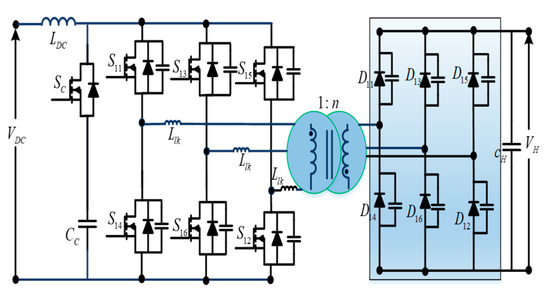
Figure 32.
Current-fed Three-Phase DC-DC converter with active clamp.
This topology has significant attributes: (i) in comparison with single-phase systems, the power exchange capacity is increased for the same-voltage and current-rated semiconductor devices [74]; (ii) with the help of the active clamping circuit, the ZVS operation in the active switches and the ZCS operation in the diodes of the rectifier are achieved; (iii) with the help of inherent boost features of the current-fed boost configuration, the turns ratio of the transformer can be decreased; (iv) with the increase in efficient switching frequency, the filter inductor at the output side can be avoided, and also the size of the DC inductor at the input side can be minimized; and (v) for the same power ratings, when compared to the single-phase converter, the conduction losses among per-phase switches and transformer windings can be decreased due to the sharing of the RMS load current among the phase legs [75]. Because of the above-mentioned benefits, this converter is most suitable for interfacing the low-voltage, high-power source with the load. However, this converter has a few limitations, such as the complex design of the control and power circuits, the greater number of semiconductor devices, and, hence, the decreased reliability.
Multilevel Topologies
- (s)
- Three-Level DC-DC Converter with LLC resonant tank [75,76]
Three-level (3L) DC-DC converters are extensively utilized in high- and medium-voltage/power applications [75,76]. Figure 33 shows a 3L converter, including an LLC resonant tank. This resonant tank is employed in the place of neutral point clamping (NPC) diodes of a two-quadrant NPC design [75]. The soft-switching operation is attained by the LLC resonant tank. This converter provides stable converter gain, which offers a fixed DC output voltage. However, this configuration has a difficult turn-off in the ZVS mode of operation. To avoid this problem, snubber capacitors can be connected across every actively controlled device to minimize the losses related to the commutation energy. At lower operating values, this decreases the overlapping region between the voltage and current of the devices, which leads to an increase in the conversion efficiency.

Figure 33.
Three-Level DC-DC converter with an LLC resonant tank.
- (t)
- Three-Phase Three-Level DC-DC converter [76]
By joining a three-level half-bridge and a full-bridge converter, along with the symmetrical duty cycle control [76], the three-phase three-level DC-DC converter is obtained, as shown in Figure 34. So, the voltage stresses on the input-side switches are decreased to 0.5 times of the input voltage. In addition, the ripple frequency of the output current is considerably improved. Hence, the need of the filter size is decreased. However, the overall converter efficiency is reduced due to this hard switching (resulting in increases in the switching losses). To overcome the above-mentioned issue, the soft-switching strategies, such as ZVS or ZCS, may be employed.

Figure 34.
Three-Phase Three-Level DC/DC converter.
3. Discussion
- A.
- Discussion on Non-isolated/Isolated power topologies
The PWM boost converter is a popular way for boosting DC voltage since it only requires a switch, a diode, and an inductor. This solution has many advantages, including ease of implementation, economical, and an effective non-isolated boost converter that can be used in most rural electrification architectures. Figure 1 shows a common outlook of the Non-Isolated DC-DC Converter (NIDC), which has buck and boost properties. NIDC structures, on the other hand, can be a good option when a high voltage conversion ratio is needed, similar to a PWM boost converter. However, in contrast to non-isolated conversion, these are restricted due to low power levels and increased cost and size. Because of their broad application, ease of implementation, and design, NIDC converters have received a lot of attention. Furthermore, these circuits can be used with a floated output or with a shared ground between the input and the output. Apart from traditional DC-DC converter-derived topologies, such as Figure 2 and Figure 3 based on the buck–boost and Cuk concepts, several improved models based on mixed SEPIC and Zeta, switched-capacitor, interleaved, and multilevel concepts have been suggested, as shown in Figure 4, Figure 5, Figure 6, Figure 8 and Figure 10, respectively. In transformer-less solar PV systems applications, a shared DC link between the input side and output side of DC-DC NIDC converters can be utilized to boost system efficiency. NIDC converters can also be designed with or without magnetic coupling. NIDC structures with no magnetic coupling and entailing only power semiconductor devices and passive components can be a convenient solution for simplifying converter development by removing the requirement for coupled magnetic design. This can be accomplished by the use of z-sources, and/or switched capacitors, and/or switched inductors. It is to be outlined that recently, the ultra-high gain step-up DC/DC converter based on the switched-inductor and improved voltage lift technique has been recently proposed for high-voltage applications in [77] and further developed in [78,79]. Moreover, the high-gain boost DC-DC converters with reduced switch voltage stress are proposed in [80], and a non-isolated symmetrical design of the voltage lift switched-inductor boost converter with higher gain and low-voltage stress across switches is suggested in [81].
If high voltage gain is needed, magnetic coupling (coupled inductor) is often useful in high-power applications, and this can increase both performance and reliability. In order to create high-gain NIDC systems, both the transformer and the coupled inductor should be used. Just the electrical separation distinguishes the non-isolated and isolated DC-DC structures. It is a key aspect for connecting this autonomous structure with the main grid. It is often useful in other applications that need low noise and EMI-free power transfer. The voltage level of electrical separation between the input and output of a DC-DC converter, which can be accomplished by a transformer or a coupled inductor, is defined by the applicable safety standard. Some delicate loads, such as medical, military, and avionics, are prone to faults and noise, and safety is an important consideration. As a result, incorporation of electrical separation is needed. Single-stage or two-stage isolated DC-DC converters can be used to achieve desired parameters. Representations of single-stage isolated DC-DC converters are seen in Figure 13, Figure 14, Figure 15, Figure 16, Figure 18, Figure 20, Figure 21 and Figure 22. The leakage inductor of the transformer in some of these converter topologies stores energy in one cycle and then feeds the load in the other cycles; these converters typically work at high frequency to keep the magnetic components small.
The DC source voltage is often transformed to high-frequency AC voltage, and fed to a high-frequency transformer. This voltage is usually a square/quasi-square-wave voltage, and voltage magnitude change takes place at the transformer place, and then finally passes through this high AC-DC for conversion to achieve the desired DC voltage. Depending on the configuration, the switching principle in isolated DC-DC converters differs. Flyback, Push–pull, Forward, Cuk & SEPIC/ZETA, DAB, Dual Half-Bridge, Half Bridge–Full Bridge, and multiport DAB converters, as seen in Figure 13, Figure 14, Figure 15, Figure 16, Figure 18, Figure 20, Figure 21 and Figure 22, are examples of well-known transformer-based isolated DC-DC systems. The SAB converter (Figure 17), full-bridge series resonant converter (Figure 22), SPCD converter (Figure 24), boost full-bridge converter (Figure 25), hybrid DC-DC converter (Figure 26), two-stage isolated BDC (Figure 27), TCM-DAB (Figure 28), high-voltage DC-DC full-bridge converter (Figure 29), three-phase current-fed DC-DC converter (Figure 30), three-phase current-fed DC-DC converter, three-level DC-DC converter with LLC resonant tank (Figure 31), and three-phase three-level DC-DC converter (Figure 32) are also discussed. As seen in Figure 31, in comparison to traditional converters, there is a family of three-level, transformer-based, isolated DC-DC systems that benefit from lower current ripples and lower voltage stresses. Flyback converters are a type of isolated buck–boost DC-DC converter that store energy in an isolation transformer, rather than a coupled inductor, during the ON state of the switch and transfer it to the load during the OFF state. In the first step of a two-stage independent DC-DC converter, an auxiliary converter may be used to pre-regulate the appropriate voltage level, as seen in Figure 27. This auxiliary circuit may be a single DC-DC converter with distinct modulation and control or a Z-source network with combined modulation and control. Impedance source networks are a new technology that provide step-up functionality without the use of external active switches, applied successfully for a number of different conversion applications. For the topological review of impedance source networks for electric power conversion, readers may refer to [82].
- B.
- Unidirectional/Bidirectional feature
HESS-based rural electrification schemes must use both bidirectional and unidirectional converters when using solar PV as one of the power sources. The extraction of power from solar PV requires only a unidirectional DC-DC converter. Bidirectional converters, on the other hand, are used to connect various ESS voltage levels. The vast majority of basic DC-DC converters are unidirectional in nature, transferring power from an input source to a load. These unidirectional converter topologies are recommended in rural electrification systems for extracting power from solar PV modules, as well as powering onboard auxiliary components, such as utilities, sensors, and protection equipment. Unidirectional semiconductor devices, such as MOSFETs and diodes, are frequently used in the configuration of such a converter. There is no way for current to flow in the opposite direction due to the use of single-quadrant switches; where only single-direction power flow is required, unidirectional power converters are chosen due to their low count of controllable switches and, as a result, easier controller implementation. It is to be noted that diodes may have less of an effect on the circuit’s power efficiency than in high-power step-down applications in the unidirectional step-up converters. When the output voltage is far greater than the rectifying diode voltage drop, designers may choose to use a diode rather than a synchronous rectifier in some applications, despite the increased power. Moving towards the lower output-voltage range in buck-derived applications, especially in voltage regulator module applications, diode power loss becomes a more influential parameter and has a significant impact on converter performance. As a result, replacing the diode with a synchronous rectifier is preferable. This circuit is now capable of pumping current in both directions. Boost-derived schemes vary from buck-derived schemes in that they have high voltages, but no broad output current. As a result, unlike with power loss, the diode voltage drop will not be a dominant force in this case. Isolation transformers, as discussed in the preceding section, can be used to improve the boost capability or to add functionality (e.g., electrical isolation). The bidirectional configuration of NIDC converters, on the other hand, can be achieved by replacing single-quadrant switching devices with bidirectional two-quadrant devices. Figure 17 shows a structural example of an isolated single-directional converter. The full-bridge DC-DC converter is a common topology in this family, especially when dealing with high-power levels, and is an appropriate choice for industrial applications. The role of BDCs is expanding as the demand for applications with storage systems and bidirectional energy transfer capacity grows in a variety of applications. These converters are employed in a variety of applications, including RE systems, railway transportation, automotive transportation, aerospace applications, elevators and escalators, uninterruptible power supplies, batteries, SCs, smart grid applications, and elevators and escalators. In theory, however, ES and bidirectional conversion can be accomplished by employing two unidirectional DC-DC converters—one to transfer power from the input to the output and the other to move power in the opposite direction. Bidirectional topologies, on the other hand, can be formed by replacing unidirectional semiconductor elements with bidirectional switches. These converters are typically used to transfer power from an input source to a load or to consume electricity. Figure 18 depicts a schematic of another popular topology in the isolated bidirectional converter class, known as a dual-active bridge (DAB) converter. This is one of the most common isolated BDC topologies produced by a unidirectional full-bridge DC-DC converter. DAB converters are useful in high-voltage/high-power systems. In the DAB topology, the phase shift between two alternating current voltage waveforms through the isolation transformer windings is adjusted to regulate energy transfer, and the control scheme is one of the more interesting subjects of study in such converter topologies.
- C.
- Voltage-Fed/Current-Fed topologies
DC-DC converters may be categorized as voltage-fed, current-fed, and impedance fed converters based on their input circuitry. The voltage-fed-type DC-DC converters are shown, e.g., in Figure 2, Figure 5, Figure 6, Figure 10, Figure 12, Figure 13, Figure 14, Figure 15, Figure 16, Figure 18 and Figure 19. On the other hand, current-fed-type DC-DC converters are represented by Figure 4, Figure 25, Figure 29, and Figure 31. The voltage-fed-type DC-DC converters, in most situations, have a capacitor-based input filter (Cin) at their source terminals and usually convert the input voltage to a lower output voltage level (neglecting multiple stages and assuming a turn’s ratio of unity for magnetic coupling).
The popular voltage-fed-type full-bridge converter suitable for high-power applications is shown in Figure 20. As shown in Figure 1, Figure 2, Figure 3, Figure 4, Figure 5, Figure 6 and Figure 8, switched-capacitor configurations in DC-DC converters, such as multilevel (flying capacitor) converters, can be categorized as non-isolated voltage-fed DC-DC converters. This class of converters typically have a fast dynamic response and are well-suited to low-power applications. Current-fed DC-DC converters, unlike voltage-fed converter topologies, have an input inductor and generally have the ability of stepping up the input voltage to a higher output voltage. Magnetic elements in some converters are assembled into a common core to minimize the size and price of the converter. Figure 27 shows a current-fed-type full-bridge converter with an input inductor and an output capacitor filter. Switching devices of voltage-fed-type full-bridge converters are not permitted to turn on at the same time (shoot-through condition). As a result, the switching patterns must provide a delay between each leg’s high- and low-side power devices. On the other side, switching devices of all legs of a current-fed full-bridge DC-DC converter cannot be turned off concurrently (open-circuit condition). As a result, there is a need for overlap timing between the high- and low-side switching patterns. In contrast to both of the previously discussed systems, impedance-sources-based DC-DC converters are immune from shooting-through and open-circuit conditions. These converters are available in both isolated and non-isolated versions, as well as with a variety of rectifier units. In order to enhance the performance, an auxiliary transformer may be added to the input side. Thanks to the fact that their input inductors can have a constant input current, current-fed DC-DC converters are very common for low-voltage HESS systems and RE applications, such as PVs and fuel cells (FCs), because they can increase the health and life of the sources. The ripple in the input current is usually reduced by using the same inductors. The adverse effects of high ripple current on low-voltage, high-current sources are reduced by this function.
In voltage-fed converters, on the other hand, the absence of an input inductor causes significant ripple current at the input. These converters, on the other hand, do not have any RHP zero. As a result, they can react more quickly than current-fed converters to the sudden changes. Usually, current-fed converters can perform a wide range of soft switching and have high performance over a wide range of power ratings in wide-input-voltage variance applications.
- D.
- Hard-Switched/Soft-Switched topologies
Based on switching type, converters are classified into two categories: soft-switching and hard-switching converters. Due to high dv/dt and di/dt during turn-ON and turn-OFF processes, hard-switching converters suffer from high EMC and EMI. Due to the fact that switching losses rise with increasing switching frequency, this is often regarded as a constraint in the case of power converters. It is to be noted that switching power losses are the main disadvantage of hard-switched converters.
Figure 34 displays a three-phase DC-DC converter based on the hard switching system. While multi-phase concepts improve the power density of DC-DC converters, higher frequencies that can be employed further minimize the sizes of passive magnetic/electric field storage components (i.e., L and C) and achieve final miniature objectives. Soft-switching converters, on the other hand, will mitigate the above downsides by using stray inductance and capacitance as part of a resonance circuit to achieve zero-voltage switching (ZVS) or zero-current switching (ZCS). Figure 16, Figure 21, Figure 24, Figure 26, Figure 27, Figure 32, and Figure 33 are the class of soft-switching power converters. Because the voltage and current during transitions are zero, these DC-DC converters can run at high frequency, therefore, allowing size and weight reductions.
There are three types of soft-switching converters: resonant load with resonant networks, active snubber switch cells, and isolated circuit with supplementary assisted configurations. Load-resonant converters are ideal for high-power applications because they reduce converter size/weight due to high-frequency operation, while maintaining the conversion performance. In DC-DC converters, LCC, LLC, CLLC, and LCL resonant networks are used in series, parallel, and series–parallel combinations. The LLC resonant converter, for example, is shown in Figure 25. Proper operation of these converters is reliant on the operating point and resonant frequency; they are unsuitable for a wide range of operating conditions. Soft-switch cells, such as quasi-resonant, active snubber, ZVS/ZCS, and ZVT/ZCT switch cells, are another type of soft-switching converter that can be used in various DC-DC converters to reduce switching turn-ON and turn-OFF losses. This figure depicts some of these types of transfer cells in DC-DC converters. Bridge systems with auxiliary circuits for soft switching on the main and secondary faces of the isolated transformer are possible. Supplementary circuits contain an auxiliary transformer/coupled inductor or an active network.
- E.
- Components count, size, and weight
Compact design, fewer number of components, and weight are always key selling points in the DC-DC converter market. In most cases, reduction of passive and active components leads to less size, weight, and cost of the converter, as well as the complete system. Generally, converters discussed under the conventional category offer a low component count and less size and weight compared to other advanced power converter topologies. Components used in different topologies, listed in Table 1 and Table 2, offer superior perception if choosing the topologies based on components count.

Table 1.
Comparison of non-isolated bidirectional converters.
Table 2.
Isolated bidirectional converters comparison.
- F.
- Wide-Voltage range of operation
For solar-powered DCMG systems, wider voltage deviations are chosen in locations where environmental situations (irradiation and temperature) vary greatly. Generally, multi-stage schemes, like cascaded and isolated topologies, can be preferred in such cases. Converters with high-frequency components, as demonstrated, e.g., in Figure 1, Figure 3, Figure 18 and Figure 21 and others, are also decent choices in this regard. This feature is available in high-gain topologies, and topologies with this feature can also be used for PV arrays with a lower voltage range, resulting in improved safety and low leakage currents from the array to the ground.
- G.
- Losses and Cooling requirement
Switching and conduction losses of semiconductor devices and parasitic losses of passive components are the causes of losses in the system. Topologies with a low component count and soft-switching techniques in HESS systems can offer fewer losses. It means mostly non-isolated converters enjoy the higher efficiency comparing to isolated topologies. Isolated topologies mostly involve multi-stage power conversion and, hence, utilize a greater number of devices and high-frequency transformers. Additionally, these HF transformers add a significant magnitude of iron and copper losses to the overall system. To reduce the losses in the isolated topologies, some topologies utilized the concept of resonant switching, as shown above.
4. Future Directions and Recent Trends
In addition to fulfilling the interconnection obligations established by National/ International Standards, cost and efficiency are important issues for MG systems. The following trends can be seen in recent developments in MG systems.
- A.
- Reducing Component Count
Single-stage power converter topologies with a reduced number of power semiconductor, energy storing, and filtering devices are becoming increasingly popular, resulting in lower costs and higher overall power conversion efficiency than previous generations.
- B.
- Increasing Input Operational Voltage Range
DC microgrids, particularly, those powered by solar PV units, are subjected to a wide range of input fluctuations in their operating conditions. High-gain converters with wide-input-voltage ranges, when combined with adaptive and intelligent control techniques, provide low-cost solutions for extracting the maximum amount of energy from various sources. These solutions have been shown to be reliable, robust, and insensitive to changes in both the load and the input voltage and current.
- C.
- Soft-Switched Converters
In general, hard-switching power converters have high switching losses, which makes them inefficient. Power switches in resonant converters that use ZVS and ZCS soft-switching techniques can result in significant reductions in switching losses. Because of this, soft-transition switching techniques, such as zero-voltage transition (ZVT) and zero-current transition (ZCT), have been developed to reduce or eliminate switching losses and stresses, thereby increasing the efficiency of converters. Only a few soft-switched DC-DC converters have been proposed and are widely used in commercial applications, in part due to the high cost of additional power components and the complexity of the control circuit; however, they are deserving of further investigation.
- D.
- Modular Structure
Small transformer-less DC-DC converter modules can be used to construct a multilevel converter system that can accommodate a wide range of input voltage variations and a large power capacity, thereby improving system reliability and lowering maintenance costs.
- E.
- Control Aspects
From the control strategies aspect, it is necessary to design a soft-switching control method with high efficiency and reliability, in which the PI control has a simple design and is suitable for linear system applications. However, it is quite tricky to practice in bidirectional power flow applications since the non-linearities exist in the BDCs.
The sliding mode control is applicable to both linear and nonlinear systems. This control scheme achieves fast and finite-time responses, as well as robustness against parameter variation. The disadvantage is that correct parameters and state information are required, which complicates matters.
Dynamic evolution control is implemented for specific applications to reduce dynamic state errors. It can improve performance by forcing it to follow the evolution path, regardless of the presence of the disturbance.
Another non-linear control approach used in BDC to achieve fast dynamic response and reference tracking characteristics is model predictive control. Although its implementation is simple, it is incapable of dealing with severe non-linear dynamic behavior.
Fuzzy logic control can be used to attain a robust response for a nonlinear and inaccurate system that is subject to uncertainty, parameter variation, and load disturbance. The design of this control is also simpler than the sliding mode approach because no prior knowledge of the system parameters is required, and less measurement is required to design the controller.
Digital control is another control method for BDCs that can be used. The benefits of this control include the ability to perform smooth switching, significantly greater flexibility than analogue electronics, high immunity to EMI, and enhanced process and fault monitoring via an external interface or a network connection. Boundary control can be used in time-varying circuit topologies. The benefits of this control include simple implementation, robustness, and the ability to eliminate voltage and current overshoots for specific applications.
5. Conclusions
DC-DC converters with storage play an important role in renewable energy systems (RESs). They enable efficient management and regulation of the energy generated and its distribution. In India, Russia, and China, the growing need for renewable energy systems presents new challenges and opportunities. DC-DC converters can meet these challenges and provide a more sustainable and efficient power system.
In India, where electricity consumption is growing rapidly, there is a need to maximize the use of renewable energy sources, such as solar and wind power. DC-DC converters can enable the conversion of DC voltage derived from RESs. In addition, energy storage allows excess energy from RESs to be stored for use during periods of low production. This increases the resilience of the energy system, allowing RESs to be used to cover a share of energy consumption. In Russia, where RESs are not so widespread, DC-DC converters with storage still play an important role in energy systems using RESs. The converters help to efficiently utilize energy from hydroelectric and wind power plants and allow storing excess energy for later use. This can be particularly useful in remote areas where power transmission wires may not be available. In China, one of the largest energy consumers in the world, renewables are playing an increasing role in the energy system. Solar and wind power are being actively developed, and DC-DC converters with storage help optimize their efficiency. China is also actively developing energy storage technology, and DC-DC converters with storage are an important part of this process. Overall, storage DC-DC converters play an important role in renewable energy systems in India, Russia, and China.
They enable efficient management and distribution of the energy generated from renewable energy sources, as well as storage of surplus energy for later use. This helps to increase grid resilience and utilize renewable energy more efficiently.
In this article, detailed organization and analysis of all the architectures and converter topologies have been reported for the selection of the correct configuration and suitable type of power converters for Microgrid system applications. Various architectures proposed for the integration of various energy sources to achieve optimum performance have been reviewed along with the detailed analysis. Upon the discussion of the attributes of the reviewed architectures and converter topologies, the following conclusions can be drawn.
- Non-isolated converters in DC microgrids are favored for their simple architectures, cheap weight and manufacturing costs, and adaptability for low- to medium-power levels.
- Isolated converters in DC microgrid layouts offer reduced noise and EMI concerns, high conversion gains, compliance with most utility grid regulations, and ease of implementation of numerous output topologies with positive and/or negative voltage rails.
- When there is only one direction of power flow, unidirectional converters are preferable. In such situations, these converters can provide benefits such as simple modulation and control, reduced complexity, and low cost.
- On the other hand, bidirectional converters can be used anytime forward and reverse power flow is required (suitability for regenerative applications). However, it necessitates the use of sophisticated FET drivers and control units.
- Input current ripples (sometimes discontinuous) and intrinsic buck characteristics plague voltage-fed converters. Fast dynamic reaction is provided by these converters. Due to qualities like continuous input current with tiny ripple and intrinsic boost characteristics, current-fed topologies can be a viable alternative to voltage-fed converters. However, due to the input inductor and RHP zero, these converters have a delayed dynamic response.
- Large switching losses, strong EMI due to high dv/dt and di/dt at switching transitions, limited switching frequency, low power density, and low efficiency are all common problems with hard-switched converters.
- Due to zero-switching losses (ZVS and ZCS), high switching frequency, better power density, and high efficiency, soft-switched converters can be a viable alternative to hard-switched converters. However, these converters required some intricate analysis.
- Non-minimum-phase systems offer a slow dynamic response, small stability margins, and often challenging control designing.
- Minimum-phase converters offer fast dynamic response, large stability margins, and easy control designing.
- There are five different HESS configurations, such as passive, SC semi-active, battery semi-active, full-active, and three-level, that are available for DC microgrid applications.
- Passive HESS configuration is a simple design and requires less cost, size, and volume. However, it has the disadvantages of low volumetric efficiency and low flexibility in HESS design, and incomplete utilization of SC capacity.
- Full-active topology is the best among all configurations. It has a good control effect, and independent control over each ES device is possible. But, it has some disadvantages, such as high initial cost, robustness, and size due to the extra controllers needed for BDCs.
- Semi-active configuration has the mixed advantages of the passive and active configurations. Primary passive with active secondary ES is the optimal solution for RE applications. This semi-active configuration offers advantages such as wide voltage ranges of operation, improving the volumetric efficiency, and less expensive than full-active topology. However, the limitations are vast, and instability in the DC bus voltage and the low volumetric efficiency of SC usage are expected in battery semi-active HESS.
Author Contributions
Conceptualization: D.R. and D.S.; methodology: D.R. and R.P.; software: D.R. and R.P.; validation: D.R., A.D. (Alexander Domyshev) and R.P.; formal analysis: D.R. and R.P.; investigation: D.R. and D.S.; data curation: A.D. (Aliona Dreglea) and M.H.D.; resources: B.L.N. and R.P. writing—original draft preparation: D.R., R.P. and D.S.; writing—review and editing: D.S., A.D. (Aliona Dreglea), M.H.D. and B.L.N.; project administration: D.R. and D.S.; supervision: M.P., D.S., and F.L.; funding acquisition: D.S. All authors have read and agreed to the published version of the manuscript.
Funding
This work was supported by a grant from the Ministry of Science and Higher Education of the Russian Federation (project no. 075-15-2022-1215).
Data Availability Statement
Not applicable.
Conflicts of Interest
The authors declare no conflict of interest.
References
- Raveendhra, D.; Poojitha, R.; Narasimharaju, B.L.; Dreglea, A.; Liu, F.; Panasetsky, D.; Pathak, M.; Sidorov, D. Part-I: State-of-the-Art Technologies of Solar Powered DC Microgrid with Hybrid Energy Storage Systems-Architecture Topologies. Energies 2023, 16, 923. [Google Scholar] [CrossRef]
- Matsuo, H.; Kurokawa, F. New Solar Cell Power Supply System Using a Boost Type Bidirectinal DC-DC Converter. IEEE Trans. Ind. Electron. 1984, IE-31, 51–55. [Google Scholar] [CrossRef]
- Caricchi, F.; Crescimbini, F.; Noia, G.; Pirolo, D. Experimental study of a bidirectional DC-DC converter for the DC link voltage control and the regenerative braking in PM motor drives devoted to electrical vehicles. In Proceedings of the 1994 IEEE Applied Power Electronics Conference and Exposition—ASPEC’94, Orlando, FL, USA, 13–17 February 1994; pp. 381–386. [Google Scholar] [CrossRef]
- Middlebrook, R.; Cuk, S.; Behen, W. A new battery charger/discharger converter. In Proceedings of the 1978 IEEE Power Electronics Specialists Conference, Syracuse, NY, USA, 13–15 June 1978; pp. 251–255. [Google Scholar] [CrossRef]
- Cuk, S. A new zero-ripple switching DC-to-DC converter and integrated magnetics. IEEE Trans. Magn. 1983, 19, 57–75. [Google Scholar] [CrossRef]
- Majo, J.; Martinez, L.; Poveda, A.; de Vicuna, L.; Guinjoan, F.; Sanchez, A.; Valentin, M.; Marpinard, J. Large-signal feedback control of a bidirectional coupled-inductor Cuk converter. IEEE Trans. Ind. Electron. 1992, 39, 429–436. [Google Scholar] [CrossRef]
- Kim, I.-D.; Paeng, S.-H.; Ahn, J.-W.; Nho, E.-C.; Ko, J.-S. New Bidirectional ZVS PWM Sepic/Zeta DC-DC Converter. In Proceedings of the 2007 IEEE International Symposium on Industrial Electronics, Vigo, Spain, 4–7 June 2007; pp. 555–560. [Google Scholar] [CrossRef]
- Song, M.-S.; Son, Y.-D.; Lee, K.-H. Non-isolated Bidirectional Soft-switching SEPIC/ZETA Converter with Reduced Ripple Currents. J. Power Electron. 2014, 14, 649–660. [Google Scholar] [CrossRef]
- Caricchi, F.; Crescimbini, F.; Capponi, F.G.; Solero, L. Study of bi-directional buck-boost converter topologies for application in electrical vehicle motor drives. In Proceedings of the APEC ‘98 Thirteenth Annual Applied Power Electronics Conference and Exposition, Anaheim, CA, USA, 15–19 February 1998; pp. 287–293. [Google Scholar]
- Lee, H.-S.; Yun, J.-J. High-Efficiency Bidirectional Buck–Boost Converter for Photovoltaic and Energy Storage Systems in a Smart Grid. IEEE Trans. Power Electron. 2019, 34, 4316–4328. [Google Scholar] [CrossRef]
- Chung, H.S.-H.; Ioinovici, A.; Cheung, W.-L. Generalized structure of Bi-directional switched-capacitor DC/DC converters. IEEE Trans. Circuits Syst. I Fundam. Theory Appl. 2003, 50, 743–753. [Google Scholar] [CrossRef]
- Chung, H.S.; Chow, W.C.; Hui, S.Y.R.; Lee, S.T. Development of a switched-capacitor DC-DC converter with bi-directional power flow. IEEE Trans. Circuits Syst. I Fundam. Theory Appl. 2000, 47, 1383–1389. [Google Scholar]
- Rahimi, S.; Rezvanyvardom, M.; Mirzaei, A. A Fully Soft-Switched Bidirectional DC–DC Converter with Only One Auxiliary Switch. IEEE Trans. Ind. Electron. 2019, 66, 5939–5947. [Google Scholar]
- Rathore, A.K.; Patil, D.R.; Srinivasan, D. Non-isolated Bidirectional Soft-Switching Current-Fed LCL Resonant DC/DC Converter to Interface Energy Storage in DC Microgrid. IEEE Trans. Ind. Appl. 2016, 52, 1711–1722. [Google Scholar]
- Zhang, J.; Lai, J.-S.; Yu, W. Bidirectional DC-DC converter modeling and unified controller with digital implementation. In Proceedings of the 2008 Twenty-Third Annual IEEE Applied Power Electronics Conference and Exposition, Austin, TX, USA, 24–28 February 2008; pp. 1747–1753. [Google Scholar] [CrossRef]
- Garcia, O.; Zumel, P.; de Castro, A.; Cobos, A. Automotive DC-DC bidirectional converter made with many interleaved buck stages. IEEE Trans. Power Electron. 2006, 21, 578–586. [Google Scholar] [CrossRef]
- Huang, X.; Lee, F.C.; Li, Q.; Du, W. High-frequency high-efficiency GaN-based interleaved CRM bidirectional buck/boost converter with inverse coupled inductor. IEEE Trans. Power Electron. 2016, 31, 4343–4352. [Google Scholar]
- Wang, Y.-F.; Xue, L.-K.; Wang, C.-S.; Wang, P.; Li, W. Interleaved high-conversion-ratio bidirectional DC-DC converter for distributed energy-storage Systems-Circuit generation, analysis, and design. IEEE Trans. Power Electron. 2016, 31, 5547–5561. [Google Scholar] [CrossRef]
- Su, B.; Wang, Y.; Wang, X.; Wang, F.; Ming, J.; Guo, Z. Multi-Phase Interleaved Bidirectional DC/DC Converter with Two-Winding Coupled Inductors. In Proceedings of the 2019 IEEE 3rd International Electrical and Energy Conference (CIEEC), Beijing, China, 7–9 September 2019; pp. 433–438. [Google Scholar] [CrossRef]
- Mayer, R.; El Kattel, M.B.; Possamai, M.D.; Bruning, C.; Oliveira, S.V.G. Analysis of a multi-phase interleaved bidirectional DC/DC power converter with coupled inductor. In Proceedings of the 2017 Brazilian Power Electronics Conference (COBEP), Juiz de Fora, Brazil, 19–22 November 2017; pp. 1–6. [Google Scholar] [CrossRef]
- Peng, F.; Zhang, F.; Qian, Z. A magnetic-less DC-DC converter for dual voltage automotive systems. In Proceedings of the Conference Record of the 2002 IEEE Industry Applications Conference. 37th IAS Annual Meeting (Cat. No.02CH37344), Pittsburgh, PA, USA, 13–18 October 2002; pp. 1303–1310. [Google Scholar] [CrossRef]
- Hafez, A.A. Multi-level cascaded DC/DC converters for PV applications. Alex. Eng. J. 2015, 54, 1135–1146. [Google Scholar] [CrossRef]
- Morales-Saldana, J.; Gutierrez, E.E.C.; Leyva-Ramos, J. Modeling of switch-mode dc-dc cascade converters. IEEE Trans. Aerosp. Electron. Syst. 2002, 38, 295–299. [Google Scholar] [CrossRef]
- Cai, W.; Fahimi, B.; Cosoroaba, E.; Yi, F. Stability analysis and voltage control method based on virtual resistor and proportional voltage feedback loop for cascaded DC-DC converters. In Proceedings of the 2014 IEEE Energy Conversion Congress and Exposition (ECCE), Pittsburgh, PA, USA, 14–18 September 2014; pp. 3016–3022. [Google Scholar] [CrossRef]
- Kashani, M.G.; Mobarrez, M.; Bhattacharya, S. Variable interleaving technique for photovoltaic cascaded DC-DC converters. In Proceedings of the IECON 2014—40th Annual Conference of the IEEE Industrial Electronics Society, Dallas, TX, USA, 29 October 2014–1 November 2014; pp. 5612–5617. [Google Scholar]
- Fan, Z.; Peng, F.Z.; Zhaoming, Q. Study of the multilevel converters in DC-DC applications. In Proceedings of the 2004 IEEE 35th Annual Power Electronics Specialists Conference (IEEE Cat. No.04CH37551), Aachen, Germany, 20–25 June 2004; pp. 1702–1706. [Google Scholar]
- Gowaid, I.A.; Adam, G.P.; Massoud, A.M.; Ahmed, S.; Holliday, D.; Williams, B.W. Quasi Two-Level Operation of Modular Multilevel Converter for Use in a High-Power DC Transformer with DC Fault Isolation Capability. IEEE Trans. Power Electron. 2014, 30, 108–123. [Google Scholar] [CrossRef]
- Khan, F.H.; Tolbert, L.M. A Multilevel Modular Capacitor-Clamped DC–DC Converter. IEEE Trans. Ind. Appl. 2007, 43, 1628–1638. [Google Scholar] [CrossRef]
- Gorji, S.A.; Ektesabi, M.; Zheng, J. Isolated switched-boost push-pull DC-DC converter for step-up applications. IEET Electron. Lett. 2017, 53, 177–179. [Google Scholar] [CrossRef]
- Kazimierczuk, M.K.; Vuong, D.Q.; Nguyen, B.T.; Weimer, J.A. Topologies of bidirectional PWM DC-DC power converters. In Proceedings of the IEEE 1993 National Aerospace and Electronics Conference-NAECON 1993, Dayton, OH, USA, 24–28 May 1993; pp. 435–441. [Google Scholar]
- Gorji, S.A.; Mostaan, A.; My, H.T.; Ektesabi, M. Non-isolated buck-boost DC-DC converter with quadratic voltage gain ratio. IET Power Electron. 2019, 12, 1425–1433. [Google Scholar] [CrossRef]
- Delshad, M.; Farzanehfard, H. A new isolated bidirectional buck-boost PWM converter. In Proceedings of the 2010 1st Power Electronic & Drive Systems & Technologies Conference (PEDSTC), Tehran, Iran, 17–18 February 2010; pp. 41–45. [Google Scholar] [CrossRef]
- Kwon, M.; Park, J.; Choi, S. A Bidirectional Three-Phase Push–Pull Converter with Dual Asymmetrical PWM Method. IEEE Trans. Power Electron. 2015, 31, 1887–1895. [Google Scholar] [CrossRef]
- Lin, B.-R.; Chen, J.-J.; Lee, Y.-E.; Chiang, H.-K. Analysis and implementation of a bidirectional ZVS dc-dc converter with active clamp. In Proceedings of the 2008 3rd IEEE Conference on Industrial Electronics and Applications, Singapore, 3–5 June 2008; pp. 382–387. [Google Scholar] [CrossRef]
- Khodabakhshian, M.; Adib, E.; Farzanehfard, H. Forward-type resonant bidirectional DC-DC converter. IEET Power Electron. 2016, 9, 1753–1760. [Google Scholar] [CrossRef]
- Zhang, F.; Yan, Y. Novel forward-flyback hybrid bidirectional DC-DC converter. IEEE Trans. Ind. Electron. 2009, 56, 1578–1584. [Google Scholar] [CrossRef]
- Zhang, Z.; Thomsen, O.C.; Andersen, M.A.E. Optimal Design of a Push-Pull-Forward Half-Bridge (PPFHB) Bidirectional DC–DC Converter With Variable Input Voltage. IEEE Trans. Ind. Electron. 2011, 59, 2761–2771. [Google Scholar] [CrossRef]
- De Souza, E.V.; Barbi, I. Bidirectional current-fed flyback-pushpull DC-DC converter. In Proceedings of the XI Brazilian Power Electronics Conference, Natal, Brazil, 11–15 September 2011; pp. 8–13. [Google Scholar]
- Aboulnaga, A.A.; Emadi, A. Performance evaluation of the isolated bidirectional Cuk converter with integrated magnetics. In Proceedings of the 2004 IEEE 35th Annual Power Electronics Specialists Conference (IEEE Cat. No.04CH37551), Aachen, Germany, 20–25 June 2004; pp. 1557–1562. [Google Scholar]
- Zhao, C.; Round, S.D.; Kolar, J.W. An Isolated Three-Port Bidirectional DC-DC Converter with Decoupled Power Flow Management. IEEE Trans. Power Electron. 2008, 23, 2443–2453. [Google Scholar] [CrossRef]
- Ruseler, A.; Barbi, I. Isolated Zeta-SEPIC bidirectional dc-dc converter with active-clamping. In Proceedings of the 2013 Brazilian Power Electronics Conference, Gramado, Brazil, 27–31 October 2013; pp. 123–128. [Google Scholar] [CrossRef]
- Max, L.; Thiringer, T. Control method and snubber selection for a 5 MW wind turbine single active bridge DC/DC converter. In Proceedings of the 2007 European Conference on Power Electronics and Applications, Aalborg, Denmark, 2–5 September 2007; pp. 1–10. [Google Scholar] [CrossRef]
- De Doncker, R.; Divan, D.; Kheraluwala, M. A three-phase soft-switched high-power-density DC/DC converter for high-power applications. IEEE Trans. Ind. Appl. 1991, 27, 63–73. [Google Scholar] [CrossRef]
- Kheraluwala, M.; Gasgoigne, R.; Divan, D.; Bauman, E. Performance characterization of a high power dual active bridge DC/DC converter. IEEE Trans. Ind. Appl. 1992, 28, 1294–1301. [Google Scholar] [CrossRef]
- Krismer, F.; Kolar, J.W. Accurate Power Loss Model Derivation of a High-Current Dual Active Bridge Converter for an Automotive Application. IEEE Trans. Ind. Electron. 2010, 57, 881–891. [Google Scholar] [CrossRef]
- Zhao, B.; Song, Q.; Liu, W.; Sun, Y. Overview of Dual-Active-Bridge Isolated Bidirectional DC–DC Converter for High-Frequency-Link Power-Conversion System. IEEE Trans. Power Electron. 2014, 29, 4091–4106. [Google Scholar] [CrossRef]
- Li, X.; Bhat, A.K.S. Analysis and Design of High-Frequency Isolated Dual-Bridge Series Resonant DC/DC Converter. IEEE Trans. Power Electron. 2010, 25, 850–862. [Google Scholar] [CrossRef]
- Chen, W.; Rong, P.; Lu, Z. Snubberless Bidirectional DC–DC Converter with New CLLC Resonant Tank Featuring Minimized Switching Loss. IEEE Trans. Ind. Electron. 2010, 57, 3075–3086. [Google Scholar] [CrossRef]
- Jung, J.H.; Kim, H.S.; Ryu, M.H.; Baek, J.W. Design Methodology of Bidirectional CLLC Resonant Converter for High-Frequency Isolation of DC Distribution Systems. IEEE Trans. Power Electron. 2013, 28, 1741–1755. [Google Scholar] [CrossRef]
- Xu, X.; Khambadkone, A.M.; Oruganti, R. A Soft-Switched Back-to-Back Bi-directional DC/DC Converter with a FPGA based Digital Control for Automotive applications. In Proceedings of the IECON 2007—33rd Annual Conference of the IEEE Industrial Electronics Society, Taipei, Taiwan, 5–8 November 2007; pp. 262–267. [Google Scholar] [CrossRef]
- He, P.; Khaligh, A. Comprehensive Analyses and Comparison of 1 kW Isolated DC–DC Converters for Bidirectional EV Charging Systems. IEEE Trans. Transp. Electrif. 2017, 3, 147–156. [Google Scholar] [CrossRef]
- Peng, F.; Li, H.; Su, G.-J.; Lawler, J. A New ZVS Bidirectional DC–DC Converter for Fuel Cell and Battery Application. IEEE Trans. Power Electron. 2004, 19, 54–65. [Google Scholar] [CrossRef]
- Li, H.; Peng, F.; Lawler, J. A natural ZVS high-power bi-directional DC-DC converter with minimum number of devices. In Proceedings of the Conference Record of the 2001 IEEE Industry Applications Conference. 36th IAS Annual Meeting (Cat. No.01CH37248), Chicago, IL, USA, 30 September 2001–4 October 2001; pp. 1874–1881. [Google Scholar] [CrossRef]
- Park, S.; Song, Y. An interleaved half-bridge bidirectional dc-dc converter for energy storage system applications. In Proceedings of the 8th International Conference on Power Electronics—ECCE Asia, Jeju, Republic of Korea, 30 May 2011–3 June 2011; pp. 2029–2034. [Google Scholar] [CrossRef]
- Morrison, R.; Egan, M. A new power-factor-corrected single-transformer UPS design. IEEE Trans. Ind. Appl. 2000, 36, 171–179. [Google Scholar] [CrossRef]
- Du, Y.; Lukic, S.; Jacobson, B.; Huang, A. Review of high power isolated bi-directional DC-DC converters for PHEV/EV DC charging infrastructure. In Proceedings of the 2011 IEEE Energy Conversion Congress and Exposition, Phoenix, AZ, USA, 17–22 September 2011; pp. 553–560. [Google Scholar]
- Chub, A.; Vinnikov, D.; Kosenko, R.; Liivik, E.; Galkin, I. Bidirectional DC–DC Converter for Modular Residential Battery Energy Storage Systems. IEEE Trans. Ind. Electron. 2020, 67, 1944–1955. [Google Scholar] [CrossRef]
- Tao, H.; Kotsopoulos, A.; Duarte, J.L.; Hendrix, M.A.M. Family of multiport bidirectional DC-DC converters. IEE Proc.-Elect. Power Appl. 2006, 153, 451–458. [Google Scholar]
- Gorji, S.A.; Ektesabi, M.; Zheng, J. Double-input boost/Y-source DC-DC converter for renewable energy sources. In Proceedings of the 2016 IEEE 2nd Annual Southern Power Electronics Conference (SPEC), Auckland, New Zealand, 5–8 December 2016; pp. 1–6. [Google Scholar] [CrossRef]
- Safaee, A.; Karimi-Ghartemani, M.; Jain, P.K.; Bakhshai, A. Time-Domain Analysis of a Phase-Shift-Modulated Series Resonant Converter with an Adaptive Passive Auxiliary Circuit. IEEE Trans. Power Electron. 2016, 31, 7714–7734. [Google Scholar] [CrossRef]
- Mao, S.; Popovic, J.; Ramabhadran, R.; Ferreira, J.A. Comparative study of half-bridge LCC and LLC resonant DC-DC converters for ultra-wide output power range applications. In Proceedings of the 2015 17th European Conference on Power Electronics and Applications (EPE’15 ECCE-Europe), Geneva, Switzerland, 8–10 September 2015; pp. 1–10. [Google Scholar] [CrossRef]
- Li, S.; Fahimi, B. State-space modelling of LLC resonant half-bridge DC–DC converter. IET Power Electron. 2020, 13, 1583–1592. [Google Scholar]
- DeDoncker, R.W.; Kheraluwala, M.H.; Divan, D.M. Power Conversion Apparatus for DC/DC Conversion Using Dual Active Bridges. U.S. Patent 5 027 264, 25 June 1991. [Google Scholar]
- Pahlevani, M.; Eren, S.; Bakhshai, A.; Jain, P. A Series–Parallel Current-Driven Full-Bridge DC/DC Converter. IEEE Trans. Power Electron. 2015, 31, 1275–1293. [Google Scholar] [CrossRef]
- Zhu, L. A novel soft-commutating isolated boost full-bridge ZVS-PWM DC-DC converter for bidirectional high power ap-plications. IEEE Trans. Power Electron. 2006, 21, 422–429. [Google Scholar]
- Zhang, Z.; Thomsen, O.C.; Andersen, M.A.E. Soft-Switched Dual-Input DC–DC Converter Combining a Boost-Half-Bridge Cell and a Voltage-Fed Full-Bridge Cell. IEEE Trans. Power Electron. 2013, 28, 4897–4902. [Google Scholar] [CrossRef]
- Yongxia, H.; Fuchang, L.; Ling, D.; Lei, W.; Luhai, B.; Zhaozhi, L.; Bo, P. Research on applications of TVS and thyristor in a pulsed power supply system used for EMG. IEEE Trans. Dielectr. Electr. Insul. 2009, 16, 979–984. [Google Scholar]
- Soo-Hong, K.; Ehsani, M.; Choon-Sam, K. High-voltage power supply using series connected full-bridge PWM converter for pulsed power applications. IEEE Trans. Dielectr. Electr. Insul. 2015, 22, 1937–1944. [Google Scholar]
- Kwang-Min, Y.; Jun-Young, L. A 10-kW two-stage isolated/bidirectional DC/DC converter with hybrid-switching technique. IEEE Trans. Ind. Electron. 2013, 60, 2205–2213. [Google Scholar]
- Ortiz, G.; Uemura, H.; Bortis, D.; Kolar, J.W.; Apeldoorn, O. Modeling of Soft-Switching Losses of IGBTs in High-Power High-Efficiency Dual-Active-Bridge DC/DC Converters. IEEE Trans. Electron. Devices 2013, 60, 587–597. [Google Scholar] [CrossRef]
- Krismer, F.; Biela, J.; Kolar, J. A comparative evaluation of isolated bi-directional DC/DC converters with wide input and output voltage range. In Proceedings of the Fourtieth IAS Annual Meeting. Conference Record of the 2005 Industry Applications Conference, Hong Kong, China, 2–6 October 2005; Volume 1, pp. 599–606. [Google Scholar]
- Ortiz, G.; Biela, J.; Bortis, D.; Kolar, J.W. 1 Megawatt, 20 kHz, isolated, bidirectional 12 kV to 1.2 kV DC–DC converter for renewable energy applications. In Proceedings of the The 2010 International Power Electronics Conference—ECCE ASIA, Sapporo, Japan, 21–24 June 2010; pp. 3212–3219. [Google Scholar]
- Hua, B.; Mi, C. Eliminate reactive power and increase system efficiency of isolated bidirectional dual-active-bridge DC-DC converters using novel dual-phase-shift control. IEEE Trans. Power Electron. 2008, 23, 2905–2914. [Google Scholar]
- Hanju, C.; Jungwan, C.; Enjeti, P.N. A Three-phase current-fed DC/DC Converter with active clamp for low-DC renewable energy sources. IEEE Trans. Power Electron. 2008, 23, 2784–2793. [Google Scholar]
- Wang, K.; Zhu, L.; Qu, D.; Odendaal, H.; Lai, J.; Lee, F. Design, implementation, and experimental results of bi-directional full-bridge DC/DC converter with unified soft-switching scheme and soft-starting capability. In Proceedings of the 2000 IEEE 31st Annual Power Electronics Specialists Conference. Conference Proceedings (Cat. No.00CH37018), Galway, Ireland, 23 June 2000; pp. 1058–1063. [Google Scholar] [CrossRef]
- Franceschini, G.; Lorenzani, E.; Cavatorta, M.; Bellini, A. 3boost a high power three-phase step-up full-bridge converter for automotive applications. IEEE Trans. Ind. Electron. 2008, 55, 173–183. [Google Scholar] [CrossRef]
- Khan, S.; Zaid, M.; Siddique, M.D.; Iqbal, A. Ultra high gain step up DC/DC converter based on switched inductor and improved voltage lift technique for high-voltage applications. IET Power Electron. 2022, 15, 932–952. [Google Scholar] [CrossRef]
- Yavari, M.; Salemnia, A.; Javadi, H. A new step-up DC-DC converter with high gain for photovoltaic applications. Int. J. Circuit Theory Appl. 2023, 51, 702–727. [Google Scholar]
- Jagtap, N.; Pattnaik, S.; Pandey, A. A High Gain Modified Voltage Lift Cell Based DC-DC Converter Using Single Switch. In Proceedings of the 2022 IEEE 1st Industrial Electronics Society Annual On-Line Conference (ONCON), Kharagpur, India, 9–11 December 2022; pp. 1–6. [Google Scholar]
- Shaw, P.; Siddique, M.D.; Mekhilef, S.; Iqbal, A. A new family of high gain boost DC-DC converters with reduced switch voltage stress for renewable energy sources. Int. J. Circuit Theory Appl. 2023, 51, 1265–1285. [Google Scholar] [CrossRef]
- Samiullah, M.; Siddique, M.D.; Iqbal, A.; Maroti, P.K.; Banerjee, S. A non-isolated symmetrical design of voltage lift switched-inductor boost converter with higher gain and low voltage stress across switches. IET Power Electron. 2022, 1–8. [Google Scholar] [CrossRef]
- Siwakoti, Y.P.; Peng, F.Z.; Blaabjerg, F.; Loh, P.C.; Town, G.E. Impedance-Source Networks for Electric Power Conversion Part I: A Topological Review. IEEE Trans. Power Electron. 2014, 30, 699–716. [Google Scholar] [CrossRef]
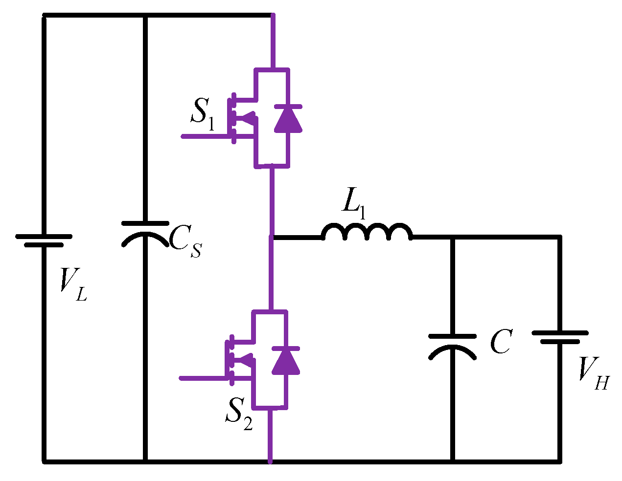
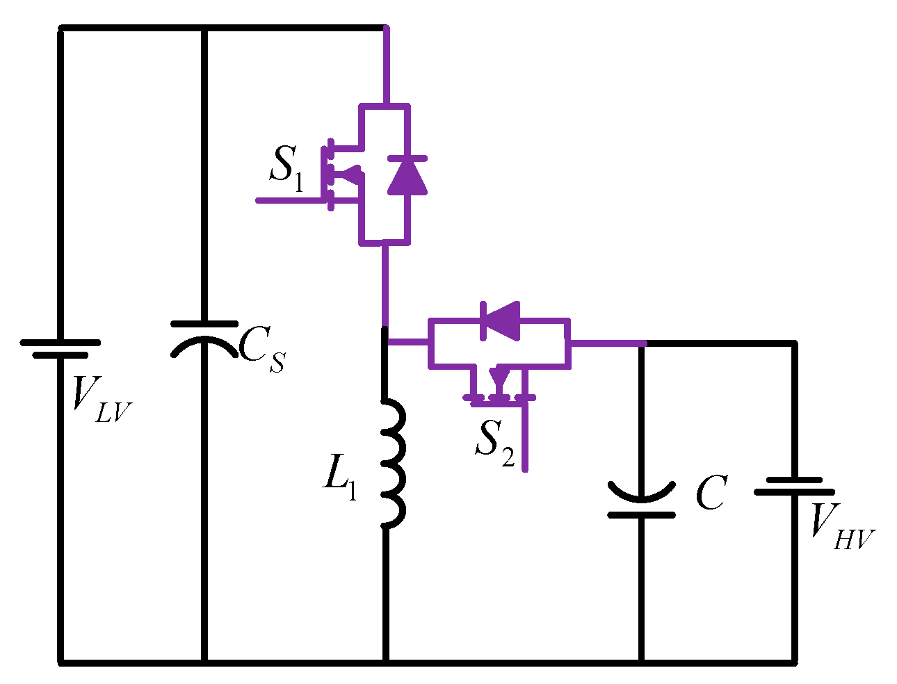


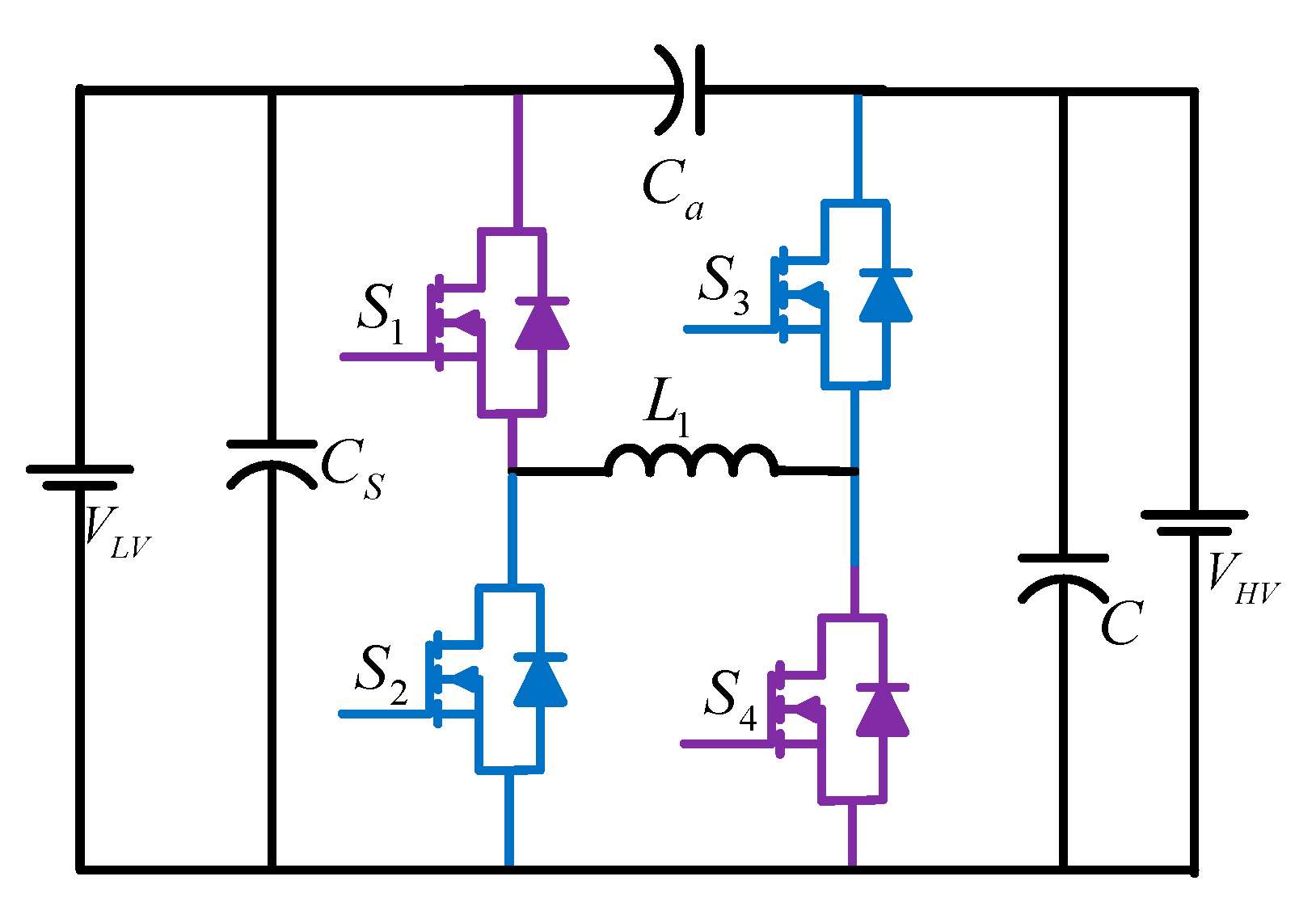
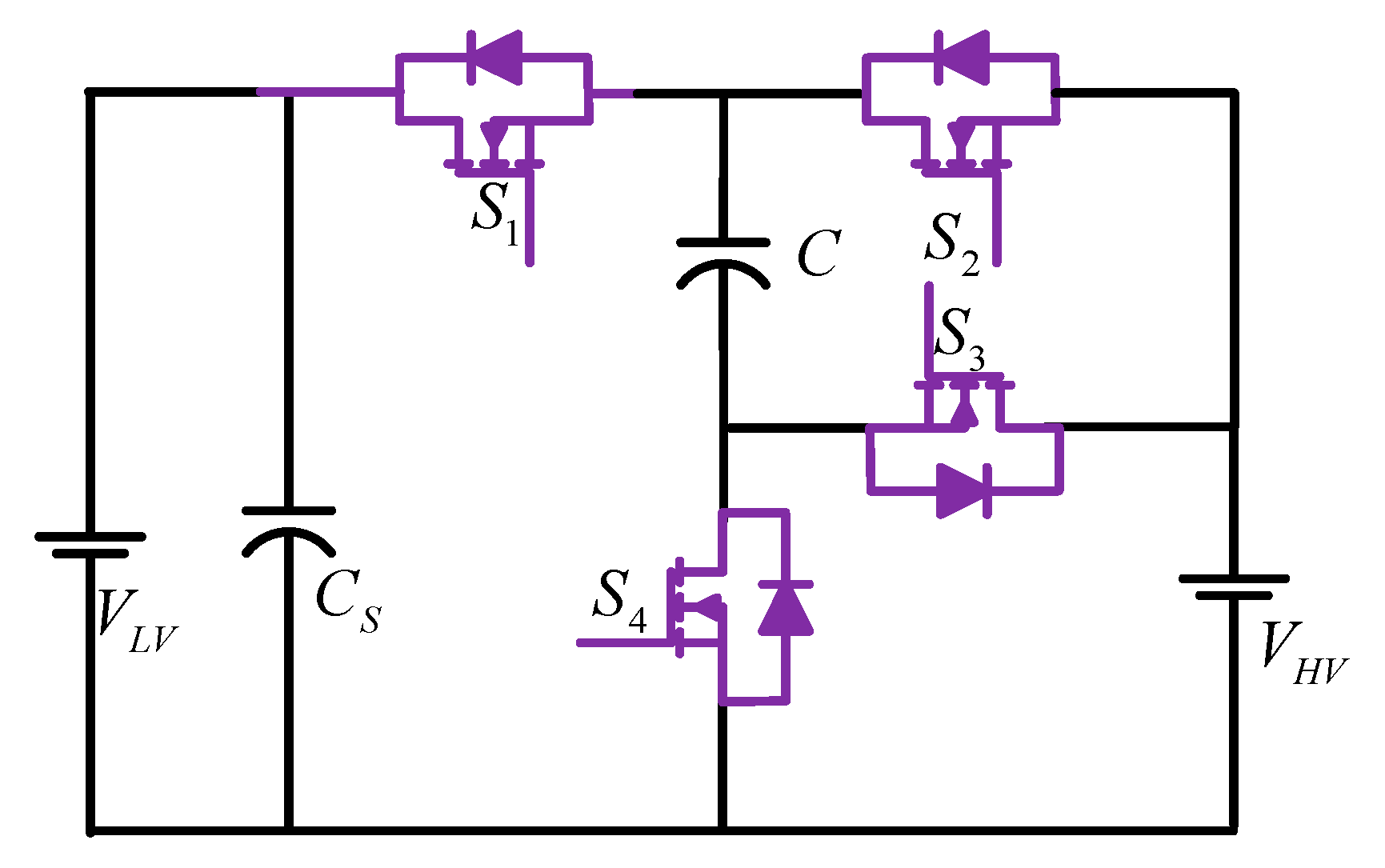
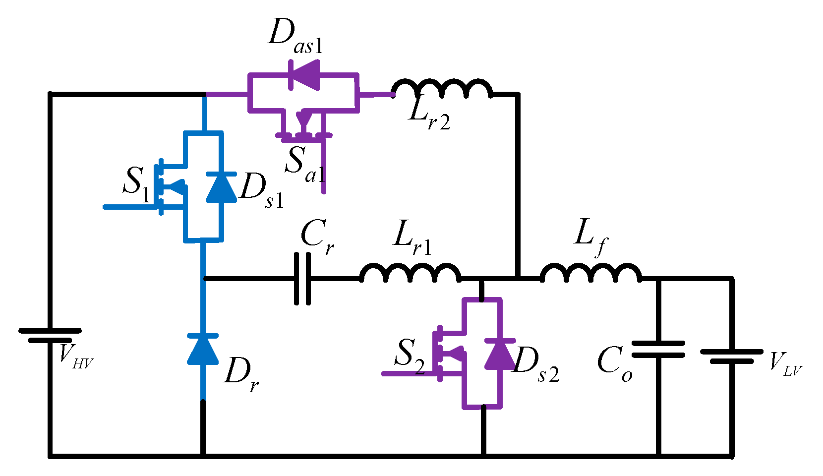

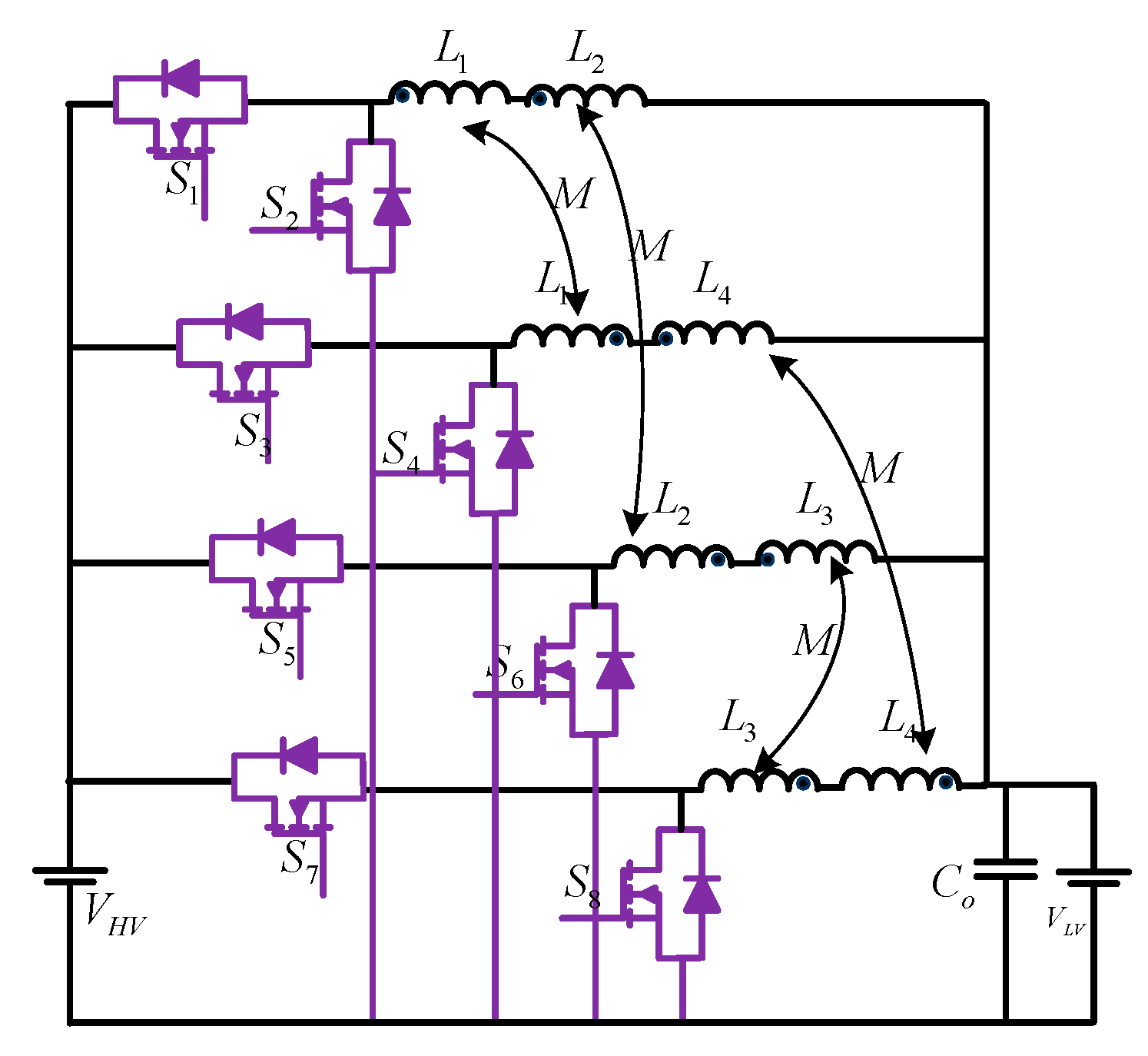

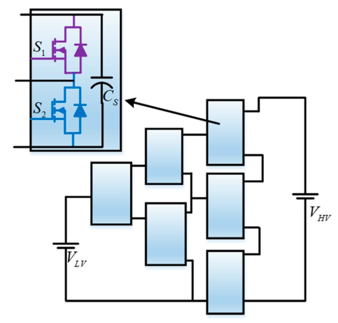
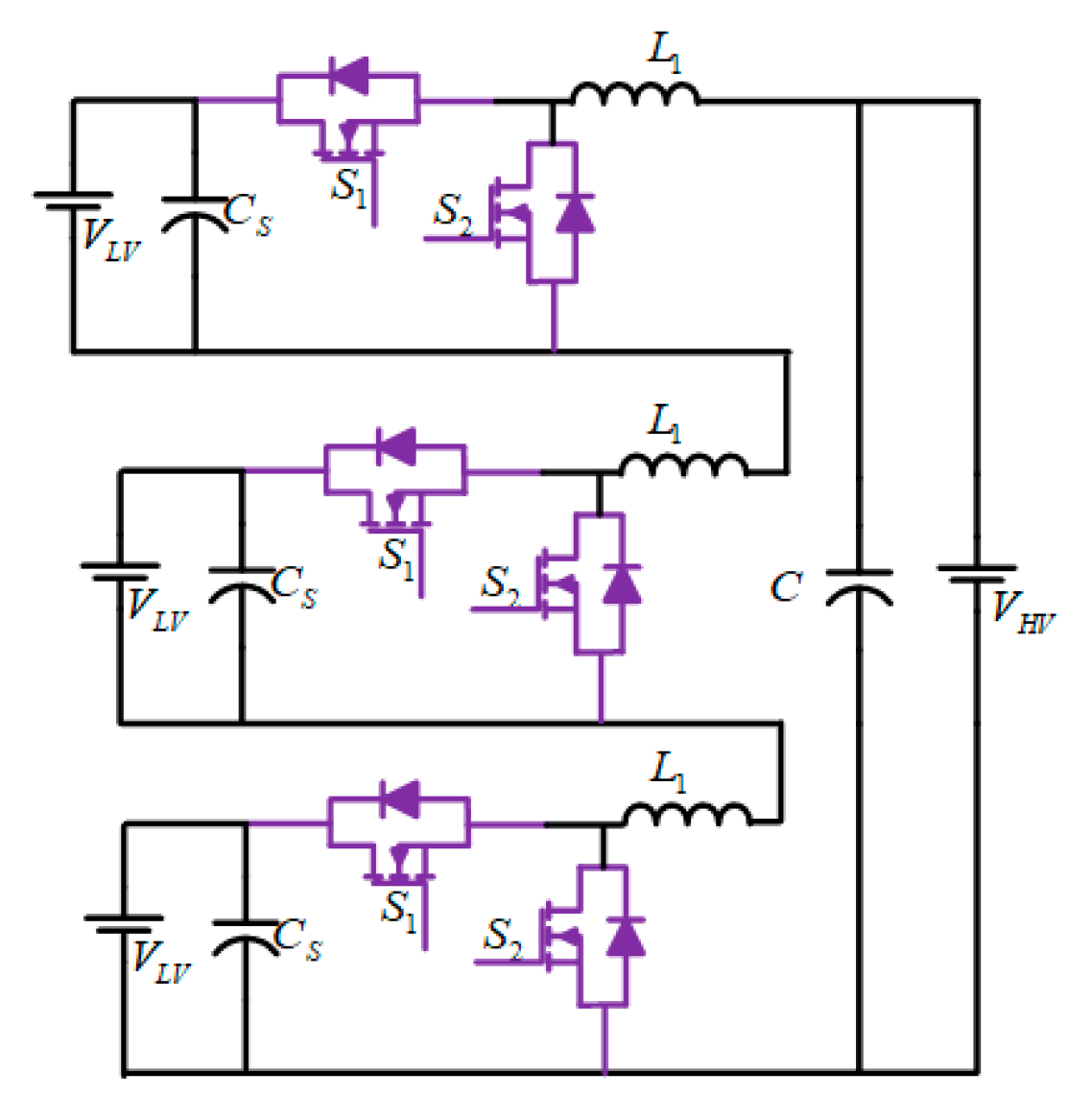
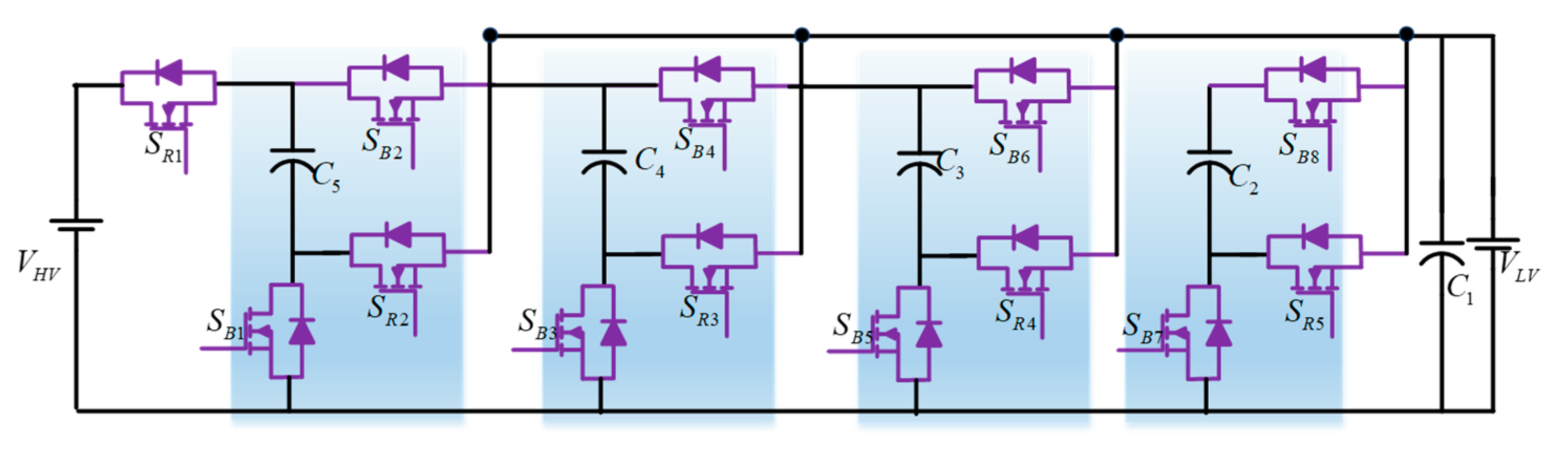
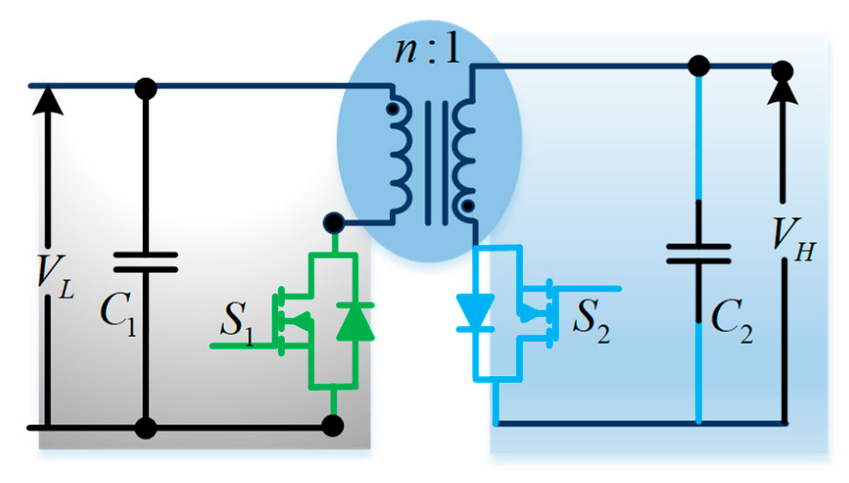


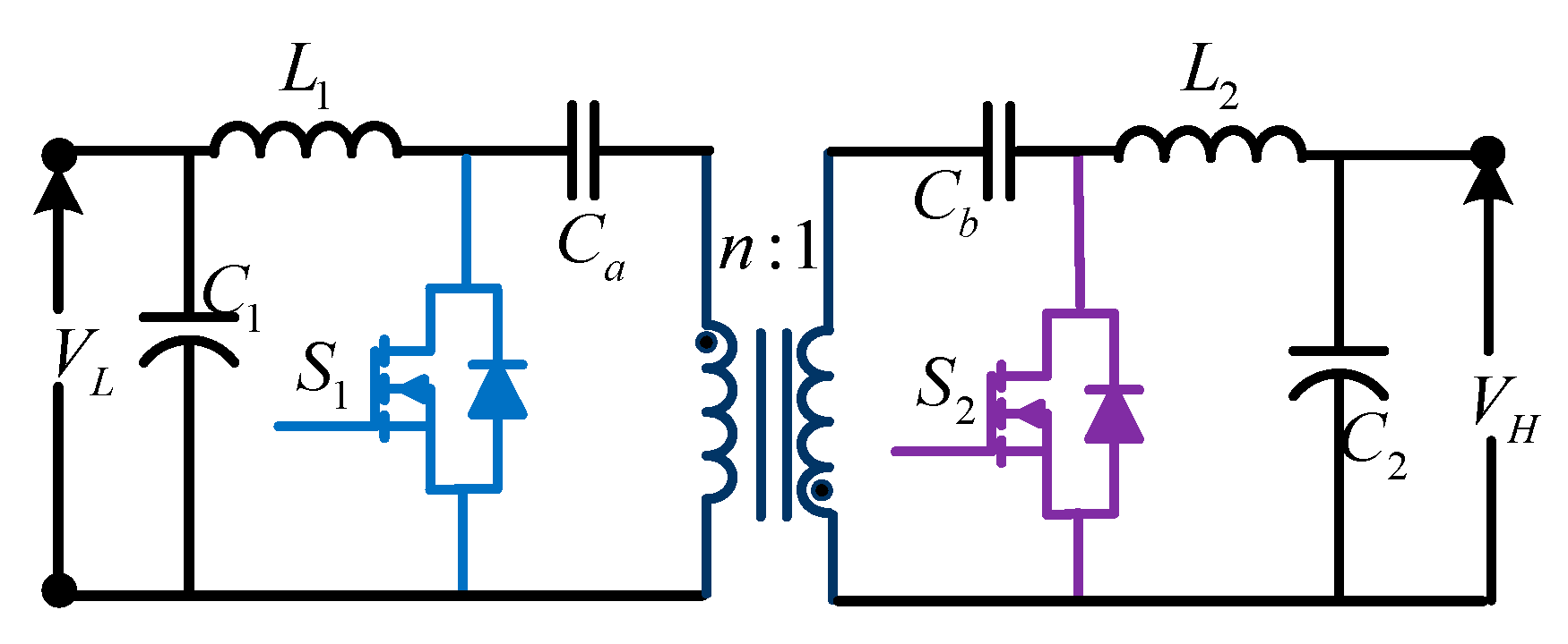
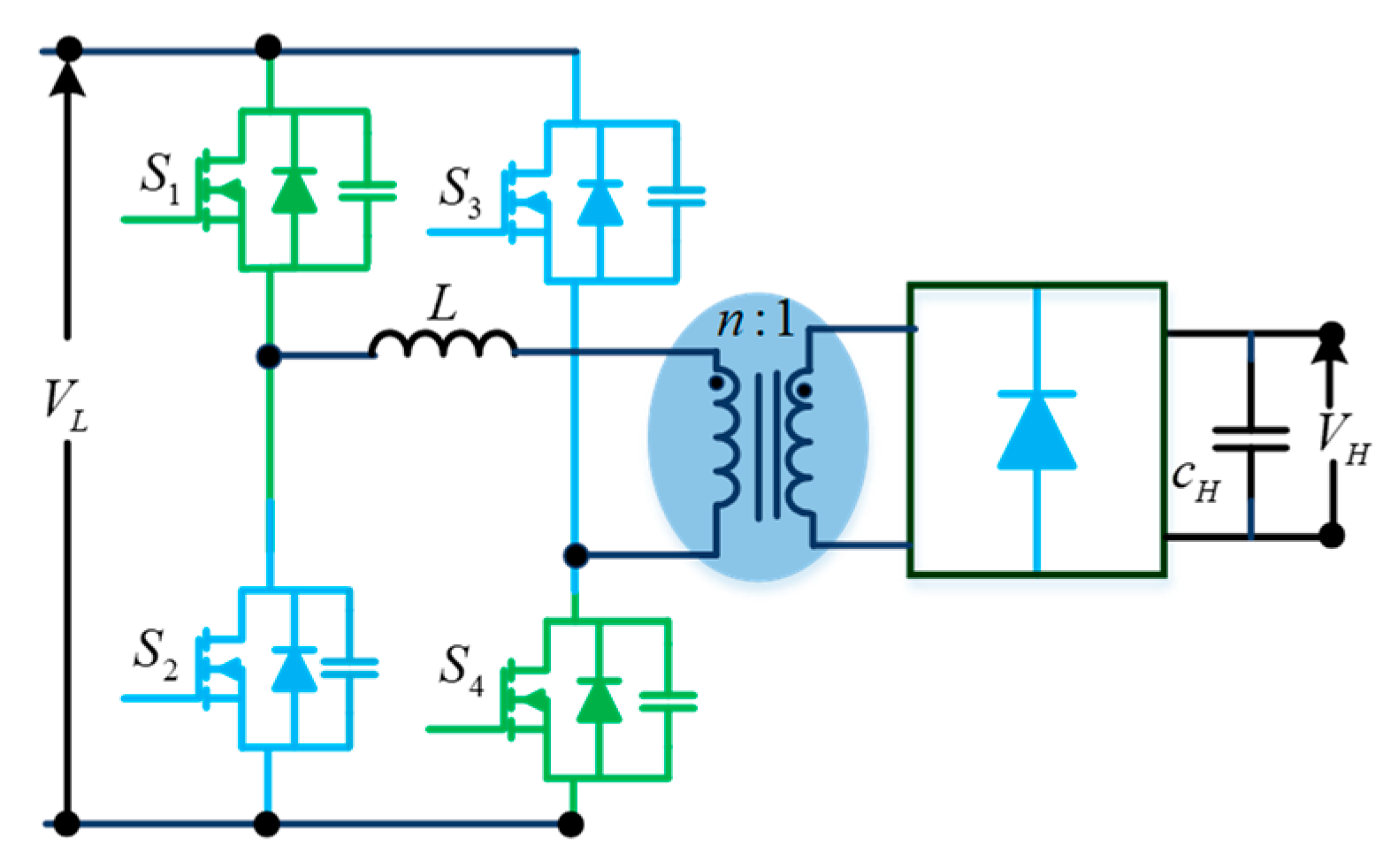

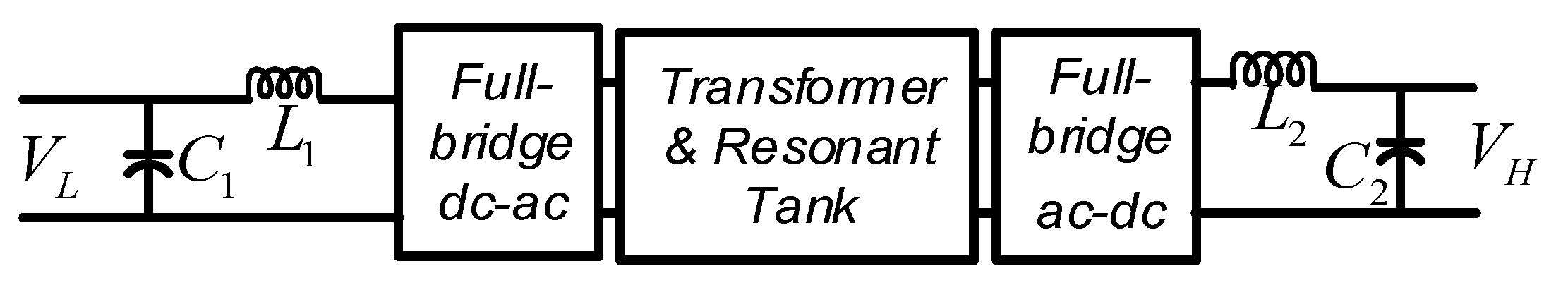
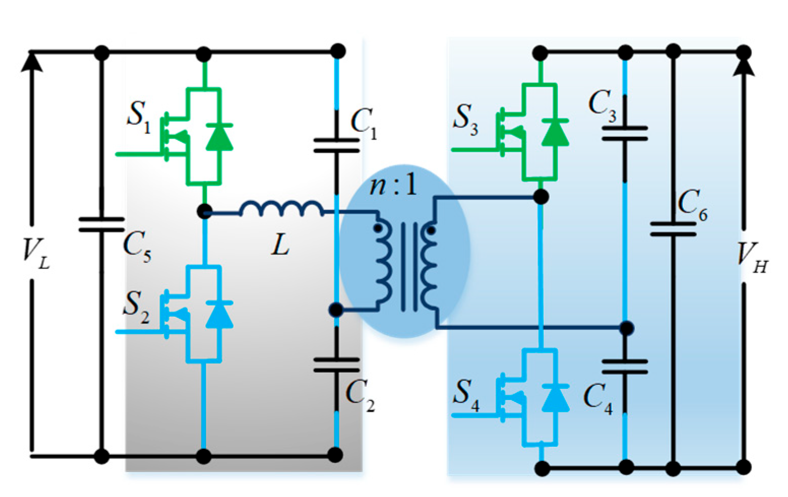
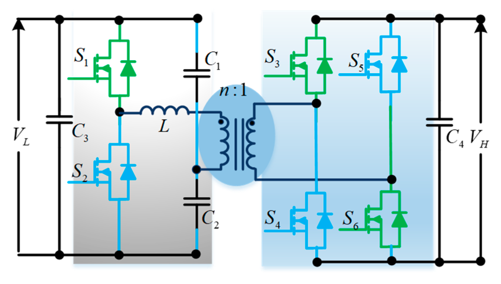
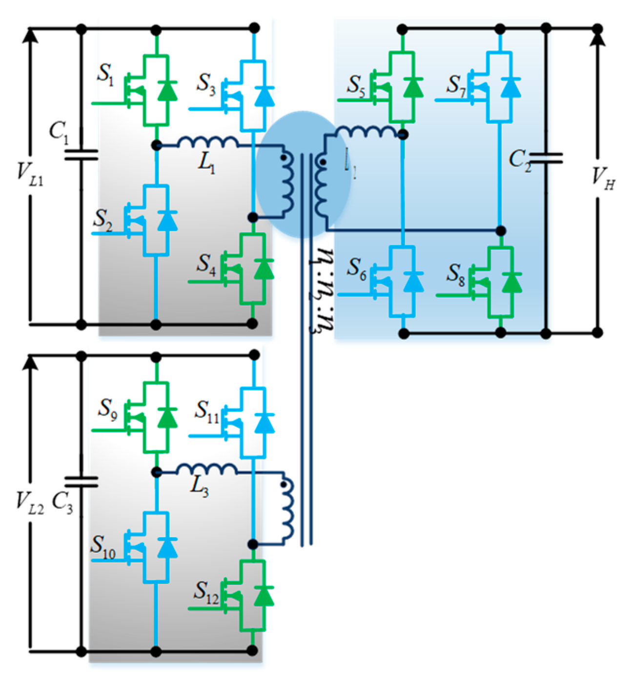

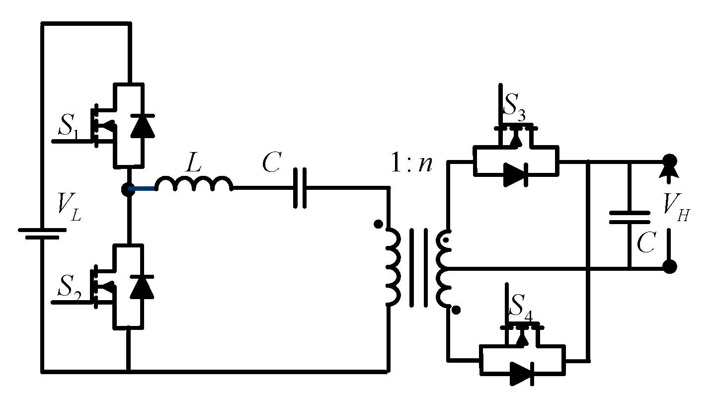
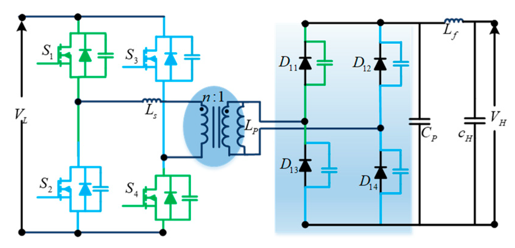
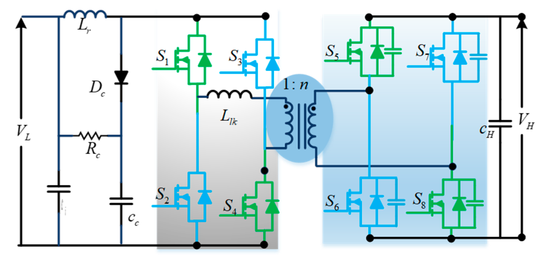

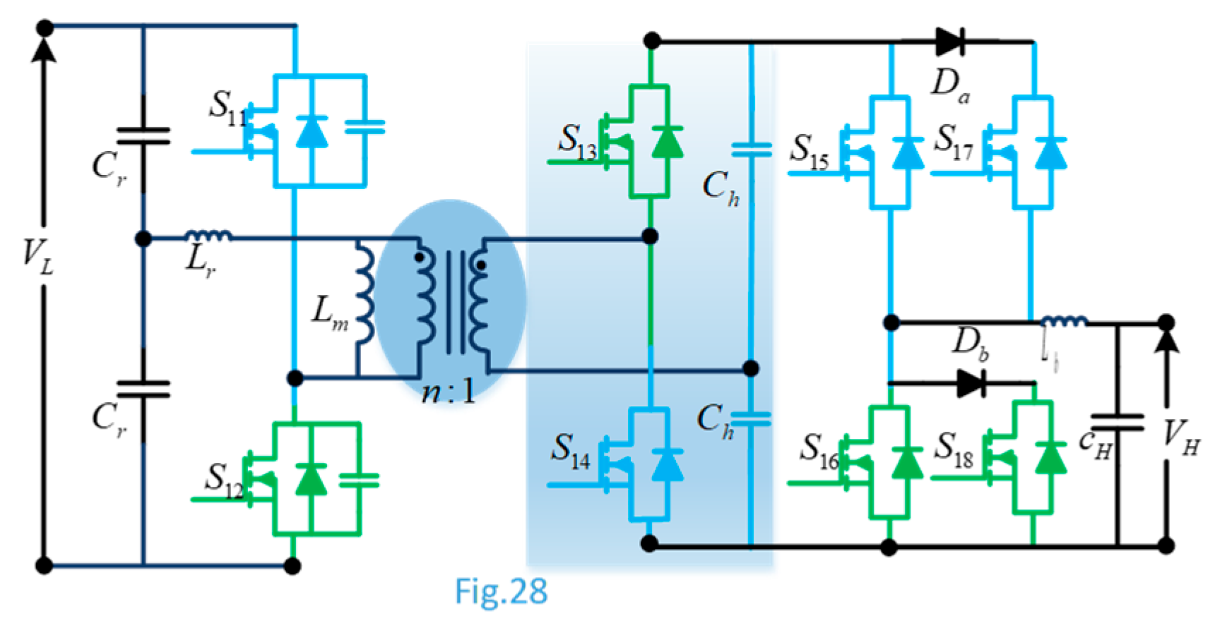

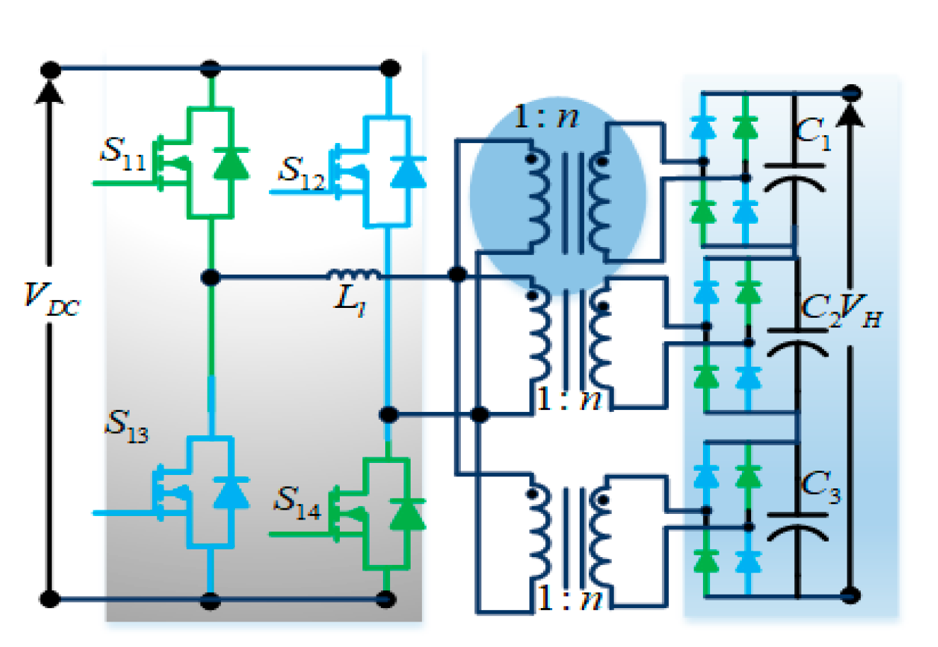
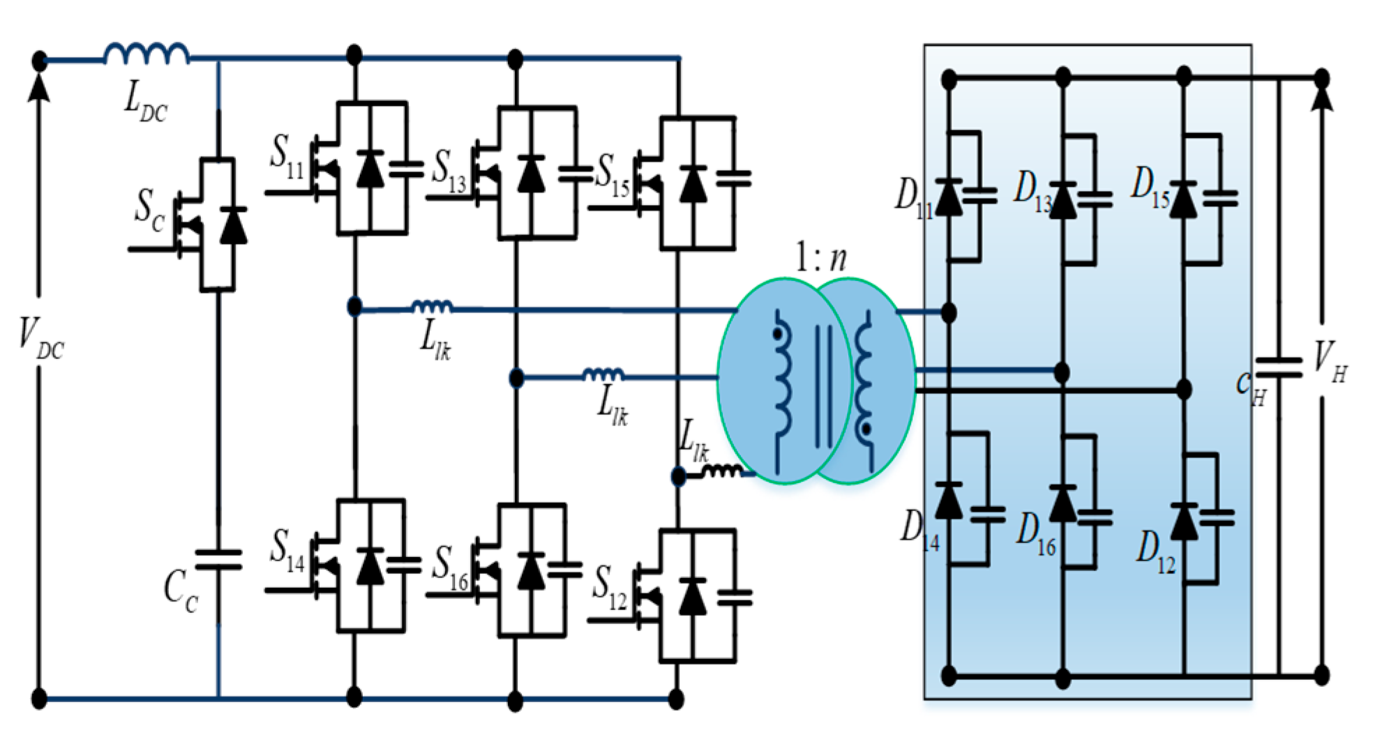
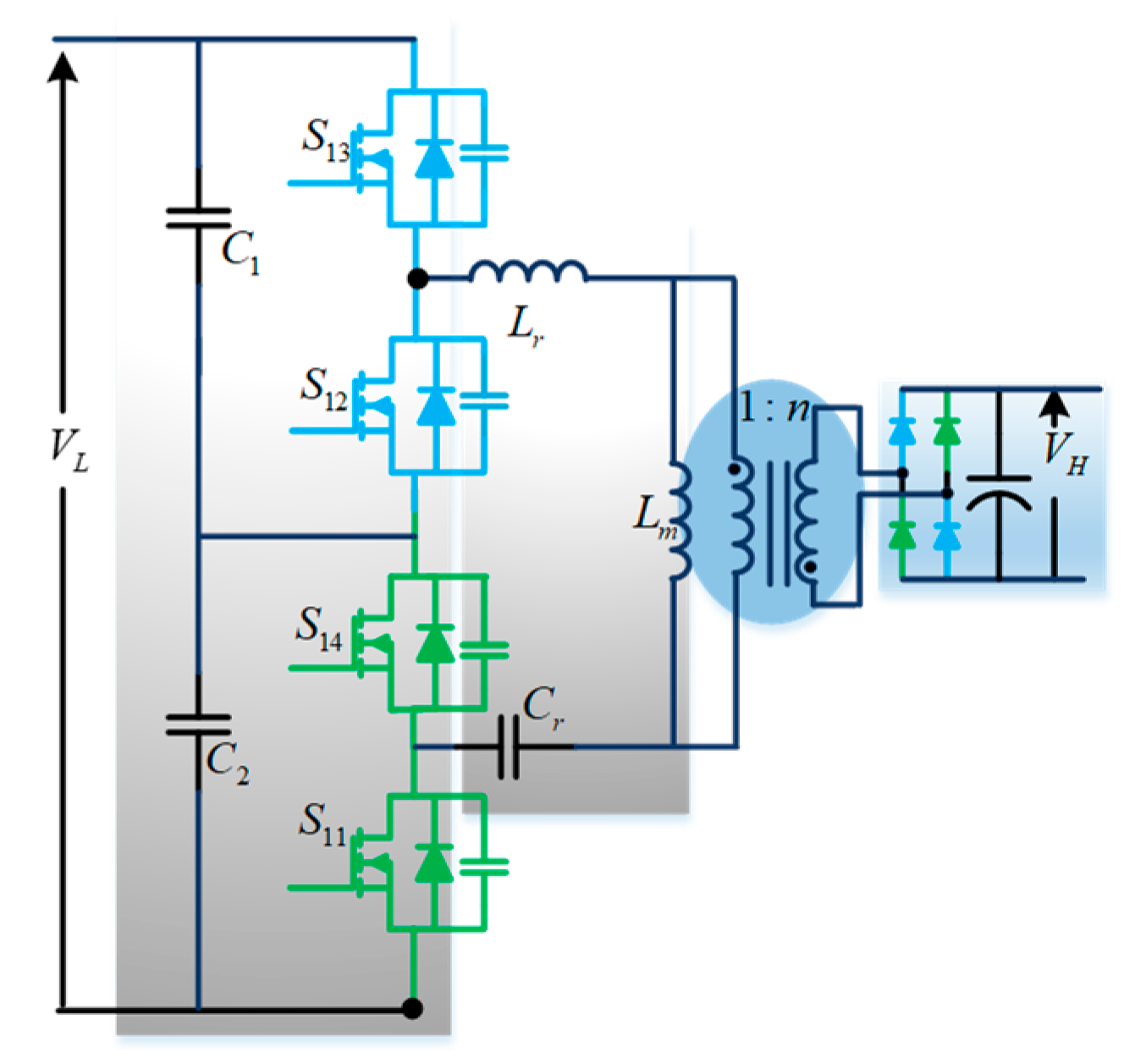
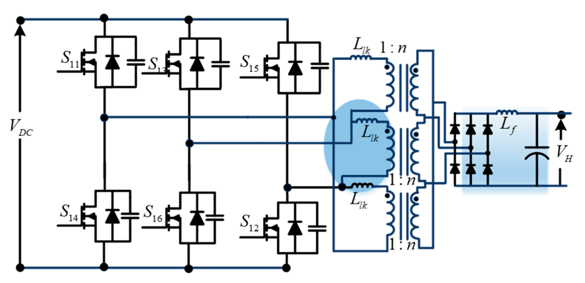
Disclaimer/Publisher’s Note: The statements, opinions and data contained in all publications are solely those of the individual author(s) and contributor(s) and not of MDPI and/or the editor(s). MDPI and/or the editor(s) disclaim responsibility for any injury to people or property resulting from any ideas, methods, instructions or products referred to in the content. |
© 2023 by the authors. Licensee MDPI, Basel, Switzerland. This article is an open access article distributed under the terms and conditions of the Creative Commons Attribution (CC BY) license (https://creativecommons.org/licenses/by/4.0/).