Article

Supplementary Control of Conventional Coordinated Control for 1000 MW Ultra-Supercritical Thermal Power Plant Using One-Step Ahead Control

1
School of Electrical and Electronics Engineering, Chung-Ang University, Seoul 06974, Republic of Korea
2
Department of Electrical and Computer Engineering, Baylor University, Waco, TX 76798-7356, USA
3
Yonsei Frontier Lab, Yonsei University, Seoul 03722, Republic of Korea
*
Author to whom correspondence should be addressed.
Energies 2023, 16(17), 6197; https://doi.org/10.3390/en16176197
Submission received: 29 June 2023 / Revised: 10 August 2023 / Accepted: 15 August 2023 / Published: 25 August 2023
(This article belongs to the Topic Power System Dynamics and Stability)

Abstract

:
The intermittence of renewable energy sources increases the importance of the effective load-tracking ability of power plants. Coordinated control between boiler and turbine systems is the uppermost layer of a thermal power plant control to follow the load demand. In this paper, a supplementary controller is proposed based on the One-Step Ahead strategy for coordinated control of thermal power plants. After a plant model is developed offline from a step response test, the optimized control of the One-Step Ahead strategy is applied to the boiler feed-forward (BFF) signal to control the electric power output and the main steam pressure simultaneously. Simulation with a 1000 MW ultra-supercritical (USC) once-through type power plant is performed. The results show that the error of Mega-Watt Output (MWO) was reduced to 78~95%, and settling time was reduced to 64~79% from conventional coordinated control by adding the proposed supplementary controller.

1. Introduction

Recently, the energy industry has faced many issues, such as environmental regulation and the need for a transition to energy diversification. As part of a solution, renewable energy sources (RESs) have been participating in power system networks, and their proportion is increasing. Despite the advantages of RESs, their intermittence and variability can cause fluctuation in a power system and thermal power plant output. Typical RESs with intermittence include wind power generation and solar power generation. Both rely on intermittent natural energy sources such as wind and solar and are independent of load demand or grid operator control. This intermittent RESs penetration presents technical challenges in all areas of power systems, including voltage regulation, load-tracking abilities, frequency stability, etc. [1,2]. Therefore, a more advanced control strategy to generate stable energy and regulate the network frequency is needed.
For a stable generation of energy with regulated frequency under a load-changing environment, both boiler and turbine systems should be controlled simultaneously. Therefore, unlike conventional boiler control problems, the controller should include the dynamics of the turbine–generator system to harmonize the slow response of the boiler with the fast response of the turbine–generator to maintain the network frequency in a stable range [3]. That is, for stable network frequency control, the Mega-Watt Output (MWO) and the Main Steam Pressure (MSP) should be controlled simultaneously under the load-changing situation.
There are two types of conventional control techniques for boiler and turbine systems [4,5]: (1) Boiler Following Type: Electrical power is first controlled by the turbine’s steam pressure, then the boiler is controlled to match the steam pressure demand. This type shows fast power-tracking performance but lacks stability. (2) Turbine Following Type: Electrical power is first controlled by the boiler’s fuel flow, then, the turbine is controlled to match the fuel demand. This type shows high stability, but power tracking performance is slow.
Since the boiler and turbine–generator are tightly coupled, an advanced control that controls the boiler and turbine simultaneously may give a better performance than a separated type. This advanced control structure is called the boiler turbine coordinated control (CC). The CC lies in the uppermost control layer of the power plant that controls two control variables, MWO and MSP, by providing additional control signals. This can match the response of the boiler and turbine during the load-changing environment.
Conventionally, the CC strategy was based on proportional–integral–derivative (PID) multi-loop control [6]. Due to its simple logic and structure, the PID controller is widely used in the industry. However, as the systems become complex, designing the controller with PID is becoming more difficult. Also, using PID control logic for complex nonlinear systems may not provide satisfactory performance. To overcome the limits of the PID controller, several efforts and research to apply an advanced modern control strategy at CC have been made. In [7], intelligent CC based on neural networks for the supercritical boiler has been investigated. More recently, Model Predictive Control (MPC) has been widely used in the modern industry. The MPC is a control theory that predicts the future output for a finite prediction horizon and calculates the optimized control input. In [8], a Generalized Predictive Control (GPC)-based CC is proposed. Dynamic Matrix Control (DMC) is also successfully adopted as a CC [9].
In this paper, we proposed a supplementary controller based on a kind of predictive control called One-Step Ahead control. One-Step Ahead control is a simple discrete control that calculates optimal input for every sampling step. Due to the simple logic, it has been successfully applied in many areas [10,11,12,13]. Also, in terms of practicality, the supplementary structure has advantages in application and maintenance. It can be easily implemented in an existing multi-loop control, and in case of an emergency, it can be removed and returned to the conventional control logic. The performance of the supplementary controller is validated by applying it to the ultra-supercritical 1000 MW once-through type power plant system, which is the worldwide mainstream of the electric power industry. The remainder of this paper is as follows: In Section 2, the full scope of the power plant model is introduced. Section 3 describes conventional and proposed boiler combustion control systems. Section 4 presents the development of the discrete prediction model and One-Step Ahead controller. Simulation results are provided in Section 5, and Section 6 presents a discussion. Finally, conclusions are drawn in Section 7.

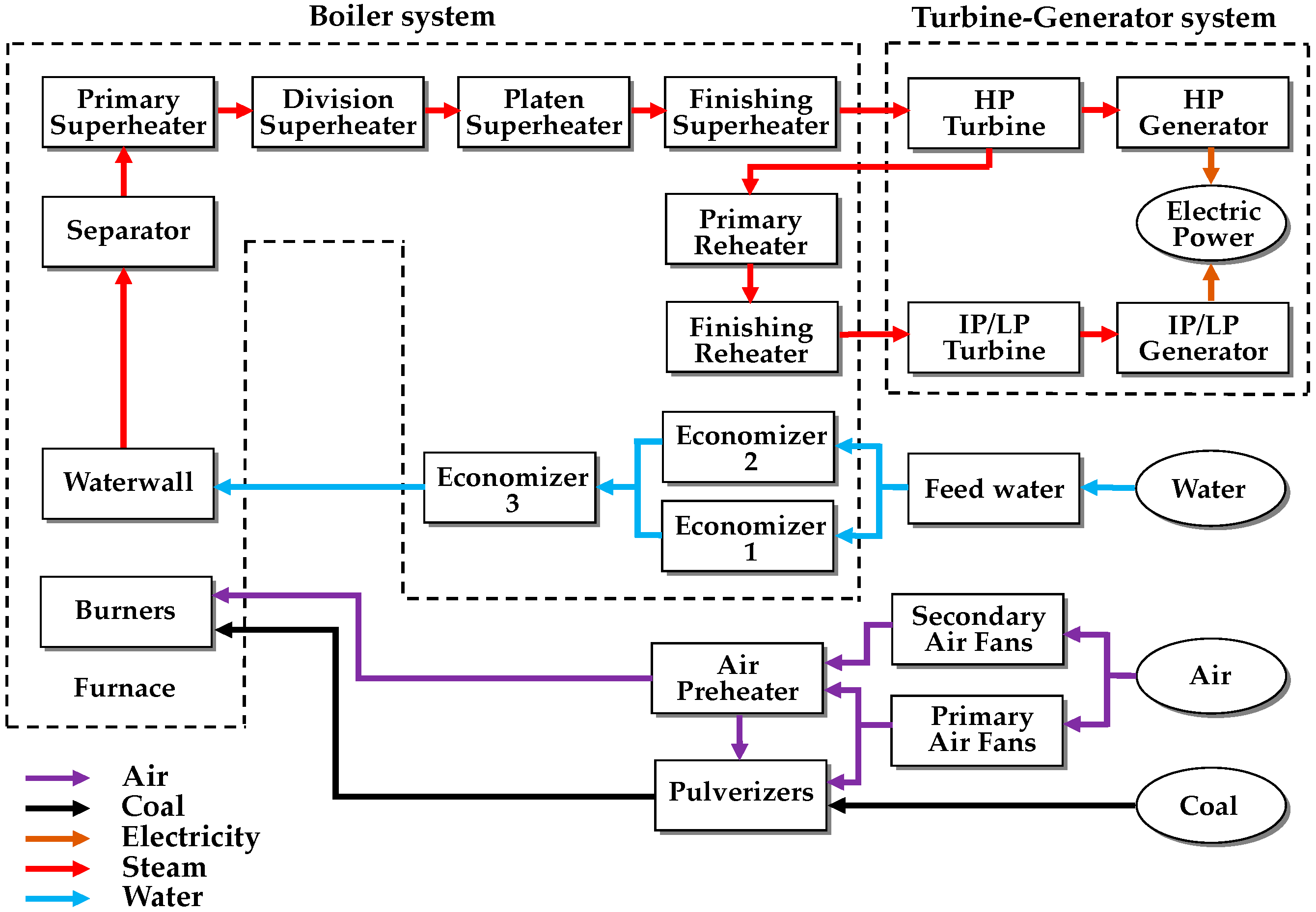
2. 1000 MW Ultra-Supercritical Once-Through Power Plant

An Ultra-Supercritical (USC) once-through type boiler has been widely used in the global thermal power plant industry for decades [9,14,15]. The USC boiler maintains the steam pressure and temperature above the critical point at a maximum of 30 MPa and 600 °C, respectively. In this extreme condition, water can be directly converted to steam, resulting in the high efficiency of the heat exchange cycle [16]. The advantage of USC boilers is not only high efficiency but also low pollutant emissions.
Figure 1 shows the simplified structure of the conventional 1000 MW USC once-through power plant, the target system of this study [17]. The pulverizers make coal to fine coal dust. Burners attached to the furnace convert the chemical energy in the coal dust into thermal energy. The hot gas produced by combustion travels all over the boiler system. This large thermal energy is absorbed by feedwater in the boiler. This means that heat exchangers such as economizers, water walls, superheaters, and reheaters heat the feed water and convert it into superheated steam. In a turbine system, the thermal energy in the superheated steam turns to mechanical energy. Finally, the mechanical energy is changed to electricity by generators. The USC power plants are a large and complex system consisting of numerous systems such as a boiler system, turbine–generator system, etc. Controlling the USC power plant is a challenge due to nonlinearity, wide operating range, strong coupling between various control loops, and so on. Among many internal control loops, the uppermost control system is the CC, which controls the boiler system and turbine–generator system simultaneously. In other words, the control variables of CC are MWO and MSP. The main purpose of CC is to quickly follow the power load demand while maintaining the internal main steam pressure stable, achieving an energy balance between the boiler and turbine [18].

3. Conventional and Proposed Boiler Combustion Control System

3.1. Conventional Boiler Combustion System in Coordinated Control

Figure 2 shows the multi-loop control structure of the conventional boiler system in the USC power plant. The red dotted block is the supplementary control proposed in this study, which is added to the existing multi-loop control structure. In the figure, the power load demand is determined by droop control and automatic generation control (AGC) in real time. The Boiler Master Demand (BMD) signal is the master signal for combustion control in the boiler system and is the same unit as the power load demand. In the F1 block, a suitable BMD signal is generated through the internal PID controller by considering the error between the set points of MWO and MSP that change according to the power load demand and the current MWO and MSP. Since the BMD signal is generated not only by MSP but also by MWO, this structure represents a typical coordinated control.
The F2–F5 blocks represent look-up tables or static nonlinear functions for unit conversion. When the BMD signal passes through the F2 block, it is converted into a boiler feed-forward (BFF) signal with a unit of coal flow, T/H. That is, the output of the F2 block before the supplementary control is added to the existing multi-loop control is the BFF signal. The BFF signal is compared with the total airflow converted to the same unit of T/H via the F5 block, and then the lower value becomes coal flow demand. Meanwhile, the F3 block converts the unit of the BFF signal into an airflow demand. It is also compared with the real coal flow converted into the same unit, and then the airflow demand is determined by a higher value.
The High/Low selector blocks in the figure show the general structure of the “cross-limit algorithm” that prevents fuel-rich conditions in a transient state [19]. When the BFF signal increases due to increased power load demand, the Low-Selector restricts the pass of the BFF signal until Total Air Flow is larger than the BFF signal. On the other hand, since the increased BFF signal is larger than the current Real Coal Flow, the BFF signal is transferred to the air controller by the High-Selector. This means that Real Coal Flow can increase after the Total Air Flow begins to increase. Conversely, when the power load demand decreases, the decreased BFF signal is passed to the coal controller by the Low-Selector, and the High-Selector limits the pass of the BFF signal until Real Coal Flow starts to decrease. That is, the decrease in Total Air Flow is conducted after the Real Coal Flow starts to decrease. Therefore, this algorithm protects the boiler system by preventing the combustion air shortage and extinguishing boiler firing, whatever the direction changes of power load demand. In conclusion, due to this protection algorithm, there is no problem with the stability of the boiler system, even if the supplementary signal is added to the BFF signal.

3.2. Proposed Supplementary Control Structure

Figure 3 shows the detailed supplementary control structure using the One-Step Ahead controller that is proposed in this study. In Figure 3, the red-dotted block is the same as the red-dotted block in Figure 2. That is, this supplementary controller is added to the existing multi-loop control in the boiler system.
In the supplementary controller, the plant output or control variables (CV) are MWO and MSP because these variables are typical CVs for safe and fast control in thermal power plants. The plant input or manipulated variables (MV) is the Δ B F F signal, which is the supplementary signal for correcting the B F F signal of conventional CC. These variables can be expressed as follows:
Y = y 1 y 2 T = y M W O y M S P T
u = Δ B F F
In the figure, the B F F s u m signal is newly defined as the sum of two B F F signals, which are the output of the F2 block in the existing boiler system and the Δ B F F signal:
B F F s u m = B F F + Δ B F F
Therefore, the supplementary control problem of CC is formulated as a Single-Input Multi-Output (SIMO) with two outputs, y M W O and y M S P , and one input in this paper. Two set points of proposed supplementary control are identical to those of conventional CC, which are y M W O , r e f and y M S P , r e f according to power load demand. This type of supplementary control strategy is simple but efficient and practical. The conventional multi-loop control structure in thermal power plants has been used for a long time in the power plant industry; therefore, plant operators are familiar with this control structure. The proposed supplementary control does not replace existing controllers but adds the supplementary control signal while maintaining the existing multi-loop control system. Therefore, it can be easily implemented and removed without affecting the existing system. In addition, plant operators can quickly return to the existing multi-loop control systems in an emergency.

4. Application to 1000 MW Ultra-Supercritical Once-Through Power Plant

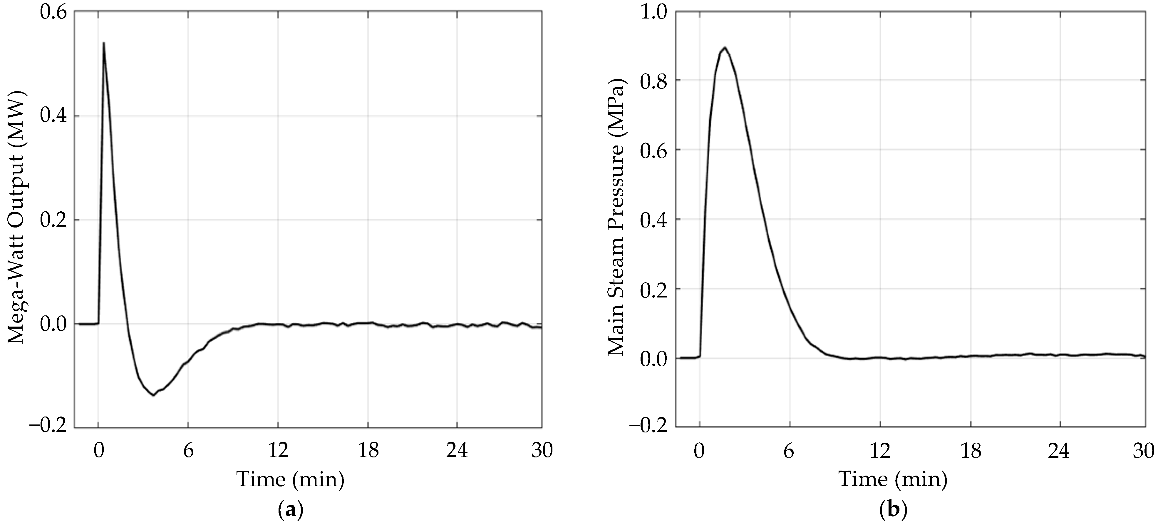
4.1. Obtaining Step Response Data

In this paper, a dynamic boiler simulation model (DBSM) called the Advanced Power and Energy System Simulator (APESS) is used for the simulation. It is an industry-proven simulator [20], and it simulates the realistic behavior of the 1000 MW USC coal-fired once-through type power plant.
The plant model for the proposed One-Step Ahead control is identified using the plant output data of the virtual plant test with DBSM. The step response test is performed at the middle load condition (850 MW), and the size of the step signal is selected as 1.03 (T/H), which is 1% of the operation range of the BFF signal.
Figure 4 shows the step responses of two CVs, MWO and MSP, respectively. In the figure, each response is represented as a normalized variation. When the plant was at a steady state of 850 MW, BFF was increased with a step at 0 s. Initially, the step increase of the BFF signal increases both coal and airflow. Then, increased mass flow raises the thermal energy of the power plant, resulting in an increase in MWO and MSP. About 50 s (0.83 min) after the step increase, both outputs started to decrease and settled down to the original value of zero. This is because the existing conventional CC in Figure 2 forces the plant to return to the original steady state corresponding to the load demand. These two-step response data are used for parameter identification to develop discrete prediction models.

4.2. Development of the Discrete Prediction Model

Since the target system is SIMO with two outputs, two output models to describe the dynamics of MWO and MSP are developed independently. The discrete prediction equation is used as a prediction model of each output as follows [21],
y ^ k + 1 = a 1 y k + a 2 y k 1 + + b 1 u k + b 2 u k 1 +
where the number of output and input history represents the order of the model.
In a discrete prediction equation, a small sampling time gives a more accurate model, but the order of the model also increases, resulting in high complexity and computational cost. Furthermore, a highly accurate model can cause overfitting. On the other hand, a large sampling time gives a simpler model, but its accuracy may become low. Considering the trade-off between model accuracy and complexity, the order of both input and output is chosen as 4, and the sampling time is chosen as 20 s. Thus, the prediction equation for output y M W O or y M S P can be represented as follows [10]:
y ^ k + 1 = a 1 y k + a 2 y k 1 + a 3 y k 2 + a 4 y k 3 + b 1 u k + b 2 u k 1 + b 3 u k 2 + b 4 u k 3
In this paper, the Least-Squares Method (LSM) is used to identify model parameters [22]. The LSM is a mathematical regression analysis used to determine the best-fit curve for a set of data by minimizing the error between the model output and plant output. For N pairs of step response data, the plant output data can be represented as a form of prediction equations as follows,
y ^ 5 = a 1 y 4 + + a 4 y 1 + b 1 u 4 + + b 4 u 1 y ^ k + 4 = a 1 y k + 3 + + a 4 y k + b 1 u k + 3 + + b 4 u k y ^ N = a 1 y N 1 + + a 4 y N 4 + b 1 u N + + b 4 u N 4
Then, the matrix form of the above equations is represented as
Y ^ = Φ X
Φ = y 4 y 1 u 4 u 1 y 5 y 2 u 5 u 2 y N 2 y N 5 u N 2 u N 5 y N 1 y N 4 u N 1 u N 4
X = a 1 a 2 a 3 a 4 b 1 b 2 b 3 b 4 T
Y ^ = y ^ 5 y ^ 6 y ^ N T
where Y ^ is a ( N 4 ) × 1 vector representing the predicted output, Φ is a ( N 4 ) × 8 matrix containing input-output data, and X is a 8 × 1 vector of model parameters to be identified.
Introducing ε = Y Y ^ , which is the error between plant output data Y and predicted data Y ^ , the cost function for modeling J M can be set as follows,
J M ( X ) = 1 2 ε 2 = 1 2 Y Y ^ 2 = 1 2 Y Φ X 2
= 1 2 ( Y Φ X ) T ( Y Φ X )
= 1 2 [ Y T Y Y T Φ X X T Φ T Y + X T Φ T Φ X ]
Then, the solution that minimizes the cost function can be found to make the gradient of J M to zero.
J M X = 1 2 X [ Y T Y Y T Φ X X T Φ T Y + X T Φ T Φ X ]
= 1 2 [ ( Y T Φ ) T Φ T Y + Φ T Φ X + ( X T Φ T Φ ) T ]
= Φ T Φ X Φ T Y = 0
Therefore, the parameter vector X is identified as
X = ( Φ T Φ ) 1 Φ T Y
This identification process is independently performed for two outputs, y M W O and y M S P , respectively. Table 1 shows the model parameters for two outputs. To evaluate the quality of the model, Figure 5 shows the comparison between the step response data and model output. In the figure, step response data is plotted in a solid black line, and the red dotted line represents the output of the prediction model. It shows that the identified model describes the plant output data successfully. It was reported that this kind of inductive identification model could show better results than a linearized model of the nonlinear physical model [23].

4.3. One-Step Ahead Controller Design

One-Step Ahead control is a discrete control that calculates optimal input for every sampling step. In this paper, the control performance of the proposed One-Step Ahead control considers both two output variables y M W O and y M S P simultaneously. Let Y k + 1 be the integrated prediction equation vector for two outputs which is
Y k + 1 = y k + 1 M W O y k + 1 M S P = a 1 M W O y k M W O + + a 4 M W O y k 3 M W O + b 1 M W O u k + + b 4 M W O u k 3 a 1 M S P y k M S P + + a 4 M S P y k 3 M S P + b 1 M S P u k + + b 4 M S P u k 3
= A 1 Y k + A 2 Y k 1 + A 3 Y k 2 + A 4 Y k 3 + B 1 u k + B 2 u k 1 + B 3 u k 2 + B 4 u k 3
= j = 1 4 ( A j Y k ( j 1 ) + B j u k ( j 1 ) )
where Y k + 1 is a 2 × 1 vector representing the predicted future output at the (k + 1)-th step, Y k ( j 1 ) is the 2 × 1 j-th output history vector, and u k ( j 1 ) is the j-th input history at the k-th step, and
A j = a j M W O 0 0 a j M S P
is the 2 × 2 constant matrix with output parameters,
B j = b j M W O b j M S P
is the 2 × 1 constant vector with input history.
In One-Step Ahead control, optimal control input that minimizes J k + 1 C , the control performance at the (k + 1)-th step is calculated every sampling step. The control performance is set as
J k + 1 C = ( Y k + 1 Y r e f ) T Q ( Y k + 1 Y r e f ) + R Δ u k 2
where Y r e f is a 2 × 1 vector of the reference value, Q is a 2 × 2 matrix representing the weight of output error, and R is the weight of input adjustment Δ u k is as follows,
Δ u k = u k u k 1
With the control performance, optimized input can be calculated by setting the gradient of J k + 1 C with respect to u k to zero as follows:
J k + 1 C u k = u k [ ( Y k + 1 Y r e f ) T Q ( Y k + 1 Y r e f ) + R Δ u k 2 ]
Substituting Y k + 1 with (20) and Δ u k with (24) gives
J k + 1 C u k = u k [ ( j = 1 4 ( A j Y k ( j 1 ) + B j u k ( j 1 ) ) Y r e f ) T Q ( j = 1 4 ( A j Y k ( j 1 ) + B j u k ( j 1 ) )     Y r e f ) + R ( u k u k 1 ) 2 ]
= 2 ( B 1 T Q B 1 + R ) u k + 2 u k ( B 1 T Q A 1 Y k + B 1 T Q A 2 Y k 1 + B 1 T Q A 3 Y k 2 + B 1 T Q A 4 Y k 3     + B 1 T Q B 2 u k 1 + B 1 T Q B 3 u k 2 + B 1 T Q B 4 u k 3 B 1 T Q Y r e f R u k 1 )
= 0
Arranging (27) and (28) with u k gives
u k = ( B 1 T Q B 1 + R ) 1 ( B 1 T Q A 1 Y k + B 1 T Q A 2 Y k 1 + B 1 T Q A 3 Y k 2 + B 1 T Q A 4 Y k 3 + B 1 T Q B 2 u k 1 + B 1 T Q B 3 u k 2 + B 1 T Q B 4 u k 3 B 1 T Q Y r e f R u k 1 )
This control law is applied at every sampling step with updated output and input history. Thus, the proposed supplementary BFF signal is applied to the conventional CC at every sampling step.
Figure 6 shows the overall algorithm of the proposed supplementary control in the form of a flow chart. In the figure, the identification process is done offline, while the One-Step Ahead control law is applied in real-time.

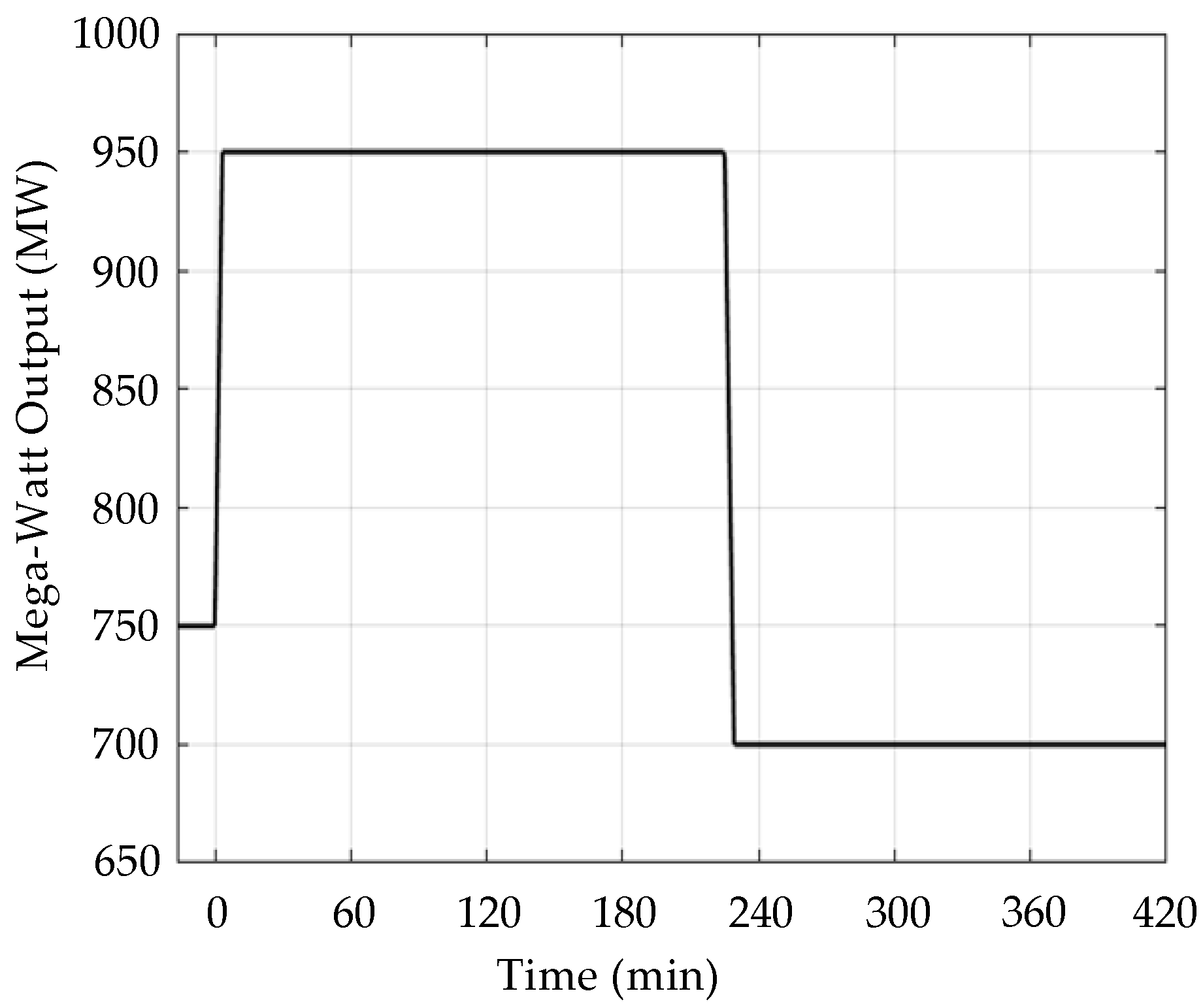
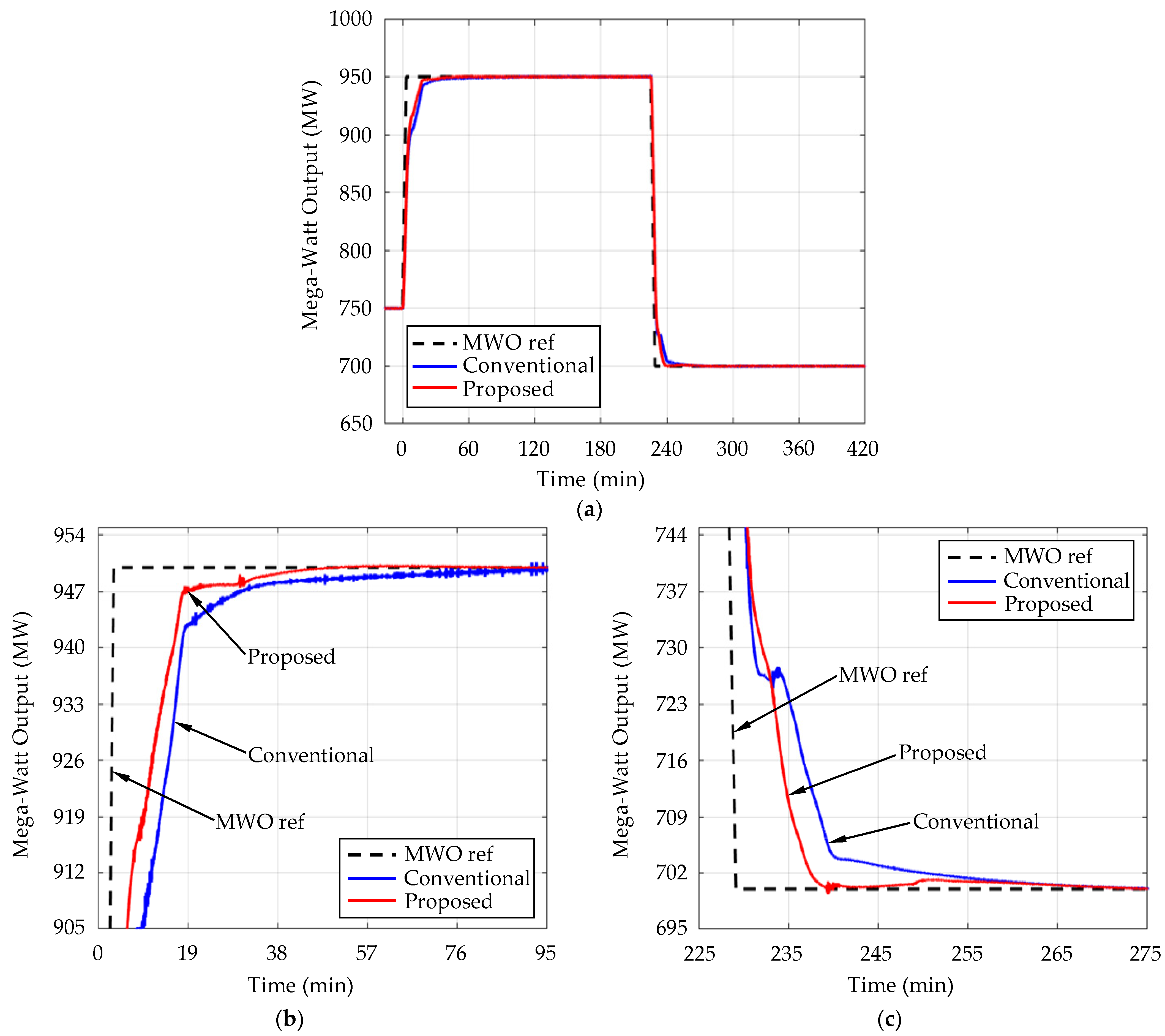
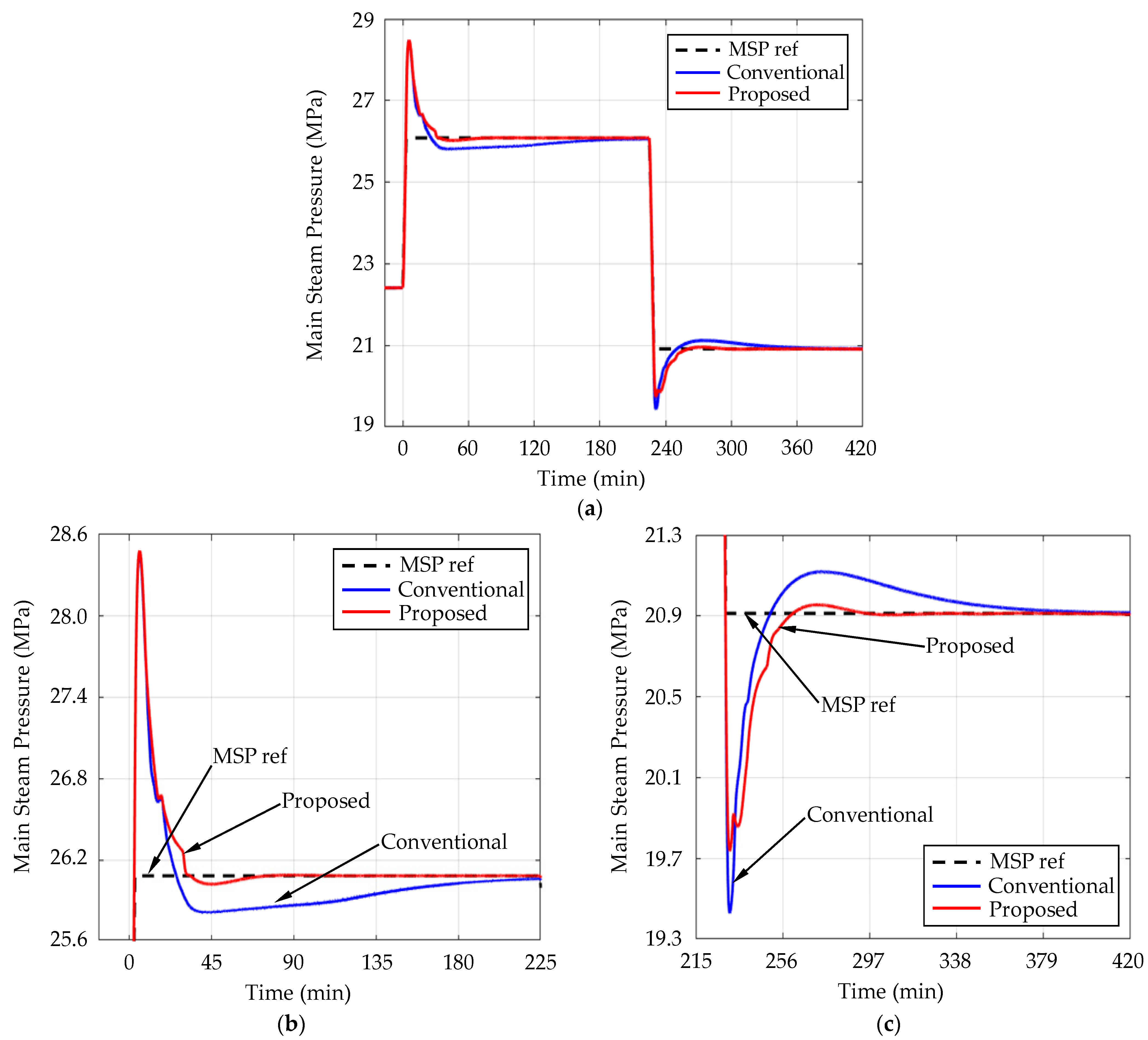
5. Simulation Results

The performance evaluation of the proposed One-Step Ahead supplementary controller is developed in MATLAB for the DBSM in a personal computer environment. The DBSM has an interface program called DBSM Editor, which can transmit and receive real-time data with MATLAB. Therefore, the supplementary control of the proposed control in MATLAB is sent to the DBSM in real time.
The simulation scenario considers two large-step changes in the power load demand. Figure 7 shows this simulation scenario for a 1000 MW USC power plant. The power load demand is first increased to 950 MW at 0 s from a steady state of 750 MW, and it is decreased to 700 MW from 950 MW at 13,500 s (225 min). To avoid abrupt changes in power load demand, the internal logic of DBSM limits the ramp rate of the power load demand to 60 MW/min, which is 6% of the total load per minute that is basically used in coal power plants [24].
Table 2 shows set points or steady-state values of two CVs used in the simulation for performance validation. The set points of MSP corresponding to each MWO are generated automatically by the internal logic of DBSM.
The weight parameters for the One-Step Ahead controller in (23) are as follows:
Q = 6 0 0 19 ,   R = 7000 .
In the cost function (23), a large element in the weight Q makes the output error corresponding to each output more important in performance, while it tends to increase input variation. On the contrary, a large weight R reduces the input variation but increases the output errors. Due to this trade-off, weight parameters are obtained to suitable values by trial and error.
Figure 8 shows the simulation results of MWO for two cases, the conventional CC without supplementary control and the conventional CC with the addition of proposed supplementary control. In the figure, the black dotted line indicates set points, the blue solid line represents the response of the existing conventional CC, and the red solid line represents the response of the CC with proposed supplementary control. Figure 8b,c show the step-up and step-down responses, respectively. In the figure, the MWO with proposed supplementary control shows a shorter rising time and settling time in both load changes.
Figure 9 shows the simulation results of MSP for two cases, the conventional CC and the CC with proposed supplementary control. Figure 9b,c show in detail the comparison of step-up and step-down responses, respectively. In the figure, the settling time of MSP is greatly reduced by adding the proposed supplementary control.
The quantitative comparison between the conventional CC with and without the proposed supplementary control is calculated. The percentage of the sum of squared errors is calculated as follows,
Percentage   of   sum   of   squared   error = t s t e ( y y r e f ) 2 d t t s t e ( y c c y r e f ) 2 d t × 100
where ts is the start time of load change, te is the end time of the transient state, yref is the set point of output, ycc is the response of conventional CC without supplementary control, and y is the response of CC with the proposed supplementary control. In the first step, ts is 0 s, and te is 13,499 s (224.98 min), and in the second step, ts is 13,500 s (225 min), and te is 25,200 s (420 min). The settling time is also compared to which output reaches within 2% of the final value. The percent ratio, which is the settling time of conventional CC with proposed supplementary control over the settling time of conventional CC, is calculated.
The percentages of error and settling time for MWO and MSP are listed, respectively, in Table 3 and Table 4. In Table 3, the error of MWO was reduced to 78~95%, and the settling time was reduced to 64~79% from those of conventional coordinated control by adding the proposed supplementary controller. In Table 4, the settling time of MSP was significantly reduced to 18~29% by the supplementary control.
Figure 10 shows the variation of the Δ B F F signal in the simulations. When the power load demand increases from 750 MW to 950 MW in the first step, the Δ B F F supplementary controller increases positively, while Δ B F F is negative in the second step. This additional correction of conventional CC resulted in performance correction for both MWO and MSP.

6. Discussion

The proposed supplementary control strategy is very simple but has shown effective performance improvements over conventional control. It has the advantage of being able to be simply implemented in the Distributed Control System (DCS) of the actual thermal power plant because it has a relatively small amount of computations compared to other advanced control strategies. In the process of calculating the optimal control input, proper tuning may be required because the performance improvement may vary somewhat due to the weight parameters of the cost function, Q and R.
Although the controller’s input and output structure is different, a similar approach using Dynamic Matrix Control (DMC) has been preceded [9]. However, this control strategy requires a large amount of computation, which can be burdensome to apply in practice. That is, it may be difficult to implement in the DCS of the existing thermal power plant, and an additional computer server may be required. Therefore, in terms of cost, the control strategy proposed in this paper is considered a relatively more practical strategy.

7. Conclusions

In this paper, to update the performance of the coordinated control (CC) of the USC thermal power plant, a supplementary control using One-Step Ahead control was proposed. The controlled variables are selected with the Mega-Watt Output (MWO) and the main steam pressure (MSP), and the manipulated variable of the supplementary controller is selected with an additional signal of the boiler feed-forward signal. The model of the supplementary controller is identified by the plant output data obtained through the offline step response test. Based on the identified model, online optimization is performed in the One-Step Ahead control algorithm. The simulation results with the 1000 MW USC power plant show that the squared error and settling time of MWO and MSP are reduced in load demand changes by adding the proposed supplementary controller. Therefore, more fast load-tracking abilities can be expected.
The proposed supplementary control structure is very practical and can be applied immediately to the currently operating thermal power plants because it adds supplementary controllers to the existing control structure. In emergency situations, because it can be easily removed, power plant operators return to familiar conventional control. In addition, the One-Step Ahead algorithm used in the supplementary controller does not require much computation compared to several previously proposed advanced controls, which need additional computer servers for complex computing. Therefore, it can be implemented directly in existing DCS of thermal power plants, which has a large cost advantage in implementation.
Nowadays, intermittent Renewable Energy Sources (RESs) penetration presents technical challenges in all areas of power systems. Proposed supplementary One-Step Ahead control to conventional coordinated control can be one of the effective strategies to prepare for the unexpected load-changing environment of power systems.

Author Contributions

U.-C.M. and H.C. designed the basic idea and the principles of the overall work. H.C. and Y.C. realized simulations. U.-C.M. prepared the initial draft of the paper, and K.Y.L. proposed some technical comments and edited the final draft of the paper. All authors have read and agreed to the published version of the manuscript.

Funding

This research was supported by the Chung-Ang University Graduate Research Scholarship in 2022 and the Korea Electric Power Corporation (Grant number: R20XO02-27).

Data Availability Statement

The data presented in this study are available on request from first author (Hyuk Choi). The data are not publicly available due to future works.

Conflicts of Interest

The authors declare no conflict of interest.

References

  1. Mlilo, N.; Brown, J.; Ahfock, T. Impact of intermittent renewable energy generation penetration on the power system networks—A review. Technol. Econ. Smart G. 2021, 6, 25. [Google Scholar] [CrossRef]
  2. Mokeke, S.; Thamae, L.Z. The impact of intermittent renewable energy generators on Lesotho national electricity grid. Electr. Pow. Syst. Res. 2021, 196, 107196. [Google Scholar] [CrossRef]
  3. Flynn, D.; Institution of Electrical Engineers. Thermal Power Plant Simulation and Control; Institution of Electrical Engineers: London, UK, 2003. [Google Scholar]
  4. Tan, W.; Liu, J.; Fang, F.; Chen, Y. Tuning of PID controllers for boiler-turbine units. ISA Trans. 2004, 43, 571–583. [Google Scholar] [CrossRef] [PubMed]
  5. Arastou, A.; Rabieyan, H.; Karrari, M. Inclusive modelling and parameter estimation of a steam power plant using an LMI-based unknown input reconstruction algorithm. IET Gener. Transm. Distrib. 2022, 16, 1425–1437. [Google Scholar] [CrossRef]
  6. Sayed, M.; Gharghory, S.M.; Kamal, H.A. Gain tuning PI controllers for boiler turbine unit using a new hybrid jump PSO. J. Electr. Syst. Inf. Technol. 2015, 2, 99–110. [Google Scholar] [CrossRef]
  7. Ma, L.; Lee, K.Y.; Wang, Z. Intelligent coordinated controller design for a 600 MW supercritical boiler unit based on expanded-structure neural network inverse models. Control Eng. Pract. 2016, 53, 194–201. [Google Scholar] [CrossRef]
  8. Gao, Y.; Zeng, D.; Ping, B.; Zhang, L.; Liu, J. Research on coordinated control system of drum boiler units considering energy demand decoupling. Control Eng. Pract. 2020, 102, 104562. [Google Scholar] [CrossRef]
  9. Lee, Y.; Yoo, E.; Lee, T.; Moon, U.C. Supplementary Control of Conventional Coordinated Control for 1000 MW Ultra-supercritical Thermal Power Plant using Dynamic Matrix Control. J. Electr. Eng. Technol. 2018, 13, 97–104. [Google Scholar]
  10. Fadali, M.S.; Visioli, A. Digital Control Engineering: Analysis and Design, 2nd ed.; Academic Press: Waltham, MA, USA, 2013. [Google Scholar]
  11. Xi, C.; Liuping, W. Discrete-time one-step ahead prediction control (DOPC) of a Quadcopter UAV with constraints. In Proceedings of the 2016 Australian Control Conference (AuCC), Newcastle, Australia, 3–4 November 2016. [Google Scholar]
  12. Xiao, Z.; Meng, S.; Lu, N.; Malik, O.P. One-Step-Ahead Predictive Control for Hydroturbine Governor. Math. Probl. Eng. 2015, 2015, 382954. [Google Scholar] [CrossRef]
  13. Dadone, A.; Dambrosio, L.; Fortunato, B. One step ahead adaptive control technique for wind systems. Energy Conv. Manag. 1998, 39, 399–413. [Google Scholar] [CrossRef]
  14. Somova, E.V.; Tugov, A.N.; Tumanovskii, A.G. Modern Coal-Fired Power Units for Ultra-Supercritical Steam Conditions (Review). Therm. Eng. 2023, 70, 81–96. [Google Scholar] [CrossRef]
  15. Cheng, C.; Peng, C.; Zeng, D.; Gang, Y.; Mi, H. An Improved Neuro-fuzzy Generalized Predictive Control of Ultra-supercritical Power Plant. Cogn. Comput. 2021, 13, 1556–1563. [Google Scholar] [CrossRef]
  16. Rocha, D.H.D.; Silva, R.J. Exergoenvironmental analysis of a ultra-supercritical coal-fired power plant. J. Clean. Prod. 2019, 231, 671–682. [Google Scholar] [CrossRef]
  17. Liu, X.J.; Kong, X.B.; Hou, G.L.; Wang, J.H. Modeling of a 1000 MW power plant ultra super-critical boiler system using fuzzy-neural network methods. Energy Convers. Manag. 2013, 65, 518–527. [Google Scholar] [CrossRef]
  18. Zhu, H.; Tan, P.; He, Z.; Zhang, C.; Fang, Q.; Chen, G. Nonlinear model predictive control of USC boiler-turbine power units in flexible operations via input convex neural network. Energy 2022, 255, 124486. [Google Scholar] [CrossRef]
  19. Dukelow, S.G.; Instrument Society of America. The Control of Boilers; Instrument Society of America: Research Triangle Park, NC, USA, 1986. [Google Scholar]
  20. Lee, K.; Jeong, K.; Jeon, W.; Bae, Y.; Lee, D. Development of APESS software for power plant simulation. In Proceedings of the ASME 2010 Pressure Vessels and Piping Conference, Washington, DC, USA, 18–22 July 2010. [Google Scholar]
  21. Zambrano, J.; Sanchis, J.; Herrero, J.M.; Martínez, M. WH-MOEA: A Multi-Objective Evolutionary Algorithm for Wiener-Hammerstein System Identification. A Novel Approach for Trade-Off Analysis Between Complexity and Accuracy. IEEE Access 2020, 8, 228655–228674. [Google Scholar] [CrossRef]
  22. Aström, K.J.; Wittenmark, B.R. Computer-Controlled Systems: Theory and Design, 3rd ed.; Dover Publications: Mineola, NY, USA, 2011. [Google Scholar]
  23. Moon, U.C.; Lee, K.Y. Step-Response Model Development for Dynamic Matrix Control of a Drum-Type Boiler–Turbine System. IEEE Trans. Energy Convers. 2009, 24, 423–430. [Google Scholar] [CrossRef]
  24. Gonzalez-Salazar, M.A.; Kirsten, T.; Prchlik, L. Review of the operational flexibility and emissions of gas- and coal-fired power plants in a future with growing renewables. Renew. Sust. Energ. Rev. 2018, 82, 1497–1513. [Google Scholar] [CrossRef]
Figure 1. A schematic of a 1000 MW ultra-supercritical once-through type power plant.
Energies 16 06197 g001
Figure 2. Conventional boiler combustion control system configuration.
Energies 16 06197 g002
Figure 3. Proposed One-Step Ahead control structure.
Energies 16 06197 g003
Figure 4. (a) Step response data of Mega-Watt Output (MWO). (b) Step response data of Main Steam Pressure (MSP).
Energies 16 06197 g004
Figure 5. (a) Comparison between step response data and model output of MWO. (b) Comparison between step response data and model output of MSP.
Energies 16 06197 g005
Figure 6. Flow chart of proposed supplementary One-Step Ahead Control.
Energies 16 06197 g006
Figure 7. Power load demand scenario of 1000 MW USC power plant.
Energies 16 06197 g007
Figure 8. (a) Comparison of the MWO with the conventional CC and the CC with proposed supplementary control. (b) Zoom of the step-up response. (c) Zoom of the step-down response.
Energies 16 06197 g008
Figure 9. (a) Comparison of the MSP with the conventional CC and the CC with proposed supplementary control. (b) Zoom of the step-up response. (c) Zoom of the step-down response.
Energies 16 06197 g009
Figure 10. Variation of the supplementary BFF signal of the proposed controller.
Energies 16 06197 g010
Table 1. Model parameter of SRMs.
Model ParameterMWOMSP
a 1 1.16311.1908
a 2 0.2096−0.0991
a 3 −0.4868−0.0428
a 4 0.0603−0.1113
b 1 0.53940.4234
b 2 −0.7389−0.2490
b 3 −0.1363−0.1308
b 4 0.3356−0.0434
Table 2. Steady-state values of CVs.
MWO (MW)MSP (MPa)
75022.409
95026.084
70020.9135
Table 3. Percentages of proposed CC/conventional CC performance for MWO.
PerformanceFirst Step ChangeSecond Step Change
Sum of squared error78.23%94.89%
Settling time 64.09%79.15%
Table 4. Percentages of proposed CC/conventional CC performance for MSP.
PerformanceFirst Step ChangeSecond Step Change
Sum of squared error93.37%94.66%
Settling time17.59%29.39%
Disclaimer/Publisher’s Note: The statements, opinions and data contained in all publications are solely those of the individual author(s) and contributor(s) and not of MDPI and/or the editor(s). MDPI and/or the editor(s) disclaim responsibility for any injury to people or property resulting from any ideas, methods, instructions or products referred to in the content.

