Abstract
Stray currents can cause very rapid degradation and material loss at the points where the current leaves the metal and enters the electrolyte. Nowadays, many resources are invested in the protection of jeopardized structures, such as buried pipelines, from stray current corrosion. This paper describes the measures that need to be considered in the design and construction of track structures to ensure high rail-to-ground resistance and consequently reduce stray currents. The main conclusions from existing guidelines and standards for reducing and controlling stray currents that are applied by various track operators are presented in the paper. Rail-to-ground resistance in different types of tracks structures and rail fastening systems is analyzed, and the optimal type of the track and type of the fastening system is defined. The grounding schemes used on the tracks and their influence on stray current values are described, as well as the influence of traction power stations (TPS) and rail cross bonding on stray current. Since it is not necessary to apply all the measures described to the same track structure, the paper gives recommendations on which measures to apply when building tracks with continuously fastened rails and which to apply when building tracks with discretely supported and fastened rails.
1. Introduction
After the first electrified railways began operating in the United States, corrosion problems were noticed on underground pipes and cables that ran near the railway line. At first, it was thought that the chemical composition of the soil caused this corrosion damage. However, it was soon concluded that soil chemistry cannot cause such serious degradation problems, and after some investigation, it was determined that the current leaking from the running rails (“stray current”) was the main cause of the corrosion problem [1,2]. These early electrified railways were not isolated from the ground and did not use rail joint bonding for good electrical continuity, both contributing to stray current leakage into the ground.
Today, rapid transits and tramways in urban areas are operated at DC with voltages that are mostly in the lower range, namely, 600V–750V [3]. There are also several systems that operate at voltages of 1500 V and 3000 V, as suburban commuter and city railways. Power is supplied by traction power stations (TPS) to the vehicles or trains via catenary/third rail and pantographs/current collectors, and in most cases rails are used as the return current path [4,5]. When traction current flows back to the TPS, the longitudinal electrical resistance of the rails causes a voltage drop and thus a difference of potential between the rails and the ground. This rail potential is variable along the track and is generally lowest at the TPS [6]. Since rails have a finite value of longitudinal resistance and usually poor insulation from earth, the traction current flowing through the rail may significantly leak into the earth and bury conductive parts before reaching the TPS. This current is referred to as stray current [7,8].
Where stray current leaks from metallic structures, corrosion and damage, overheating, arcing, and fire can occur. In an extreme case, signaling and communications systems with low noise immunity can be disrupted, endangering people and equipment inside and outside the track or train [9,10]. In the case of proximity between DC and AC railways, when the signaling system of the latter uses DC relays, stray current from the DC system may couple and cause serious interference [11,12,13].
For corrosion to occur on an electrically continuous metal structure, two conditions must be met: the metal must have a different potential on its surface, i.e., anodic and cathodic parts, and the metal must be in contact with an electrolyte. Due to the potential difference between the metal and the conductive electrolyte, electrochemical corrosion occurs. At the anode, iron is oxidized, releasing ferrous ions into the electrolyte, which results in the dissolution or loss of metal [14], as shown in reaction (i). The cathodic reaction varies with the type of electrolyte. Reaction (ii) represents the reaction that occurs in a neutral or alkaline electrolyte, and reaction (iii) occurs in an acidic electrolyte [2]. The electrochemical cell is set up between the anodic and cathodic sites, where reactions occur simultaneously, caused by an external voltage source [15,16,17].
Stray current corrosion occurs at the point where current leaves the conductor and passes into the electrolyte. The dynamic nature of the stray current generated by DC traction systems is due to the changes in the potential between rail and ground in the track. These variations are influenced by the acceleration and deceleration of transit vehicles and by the number and location of vehicles in the system [18,19,20].
Stray current leaks from the rails to the ground or into an underground metallic structure [21]. As said, two areas can be identified: the cathodic area is where the current enters the metallic structure from the ground, and the anodic area occurs where the current leaves the metal and enters the electrolyte. In the anodic region, metal dissolution occurs, and metal loss can be calculated using Faraday’s Law [22]. The stray current circuit for a concrete track slab is schematically shown in Figure 1.
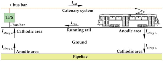
Figure 1.
Arrangement of stray current flow.
The amount of generated stray current depends largely on the type of track, on the insulation of the rails and of the fastening system, on the track maintenance, on the TPS separation, on the grounding systems of the track, on the types of vehicles and driving style, etc. [6,17].
The most common type of corrosion in urban railway tracks is stray current induced corrosion, where direct current leaks from the rail and metallic components of the fastening system to the supporting structure, through accumulated soil and water, resulting in large material losses for the rail and fastening system [2].
Track corrosion can be divided into general corrosion, which normally takes place on large rail surfaces, and localized corrosion. The typical form of localized corrosion on rail is crevice corrosion, mostly between the elastic clip and rail foot or rail foot and elastic rail pad, where the accumulation of corrosive media, including chloride ions and maybe microbes, can easily take place [23]. The rail foot has the thinnest cross-section and is the only part of the rail that comes into contact with the fastening system, so the thinning of the rail foot due to corrosion processes can be very dangerous and compromise rail stability [23,24], especially with load and stress concentration caused by traffic [25]. When this occurs in a closed track formation (such as a street section), it is not noticed until the track is opened, so traffic safety may be compromised.
According to [26] corrosion typically causes very intricate defect shapes growing in unpredictable directions and forming sharp angles and corrosion pits. These defects cause stress concentrations under loading, which can initiate or accelerate crack formation and cause fatigue failure [27].
The effects of stray current on rail and fastening system components are discussed in [28,29], where several rail samples fastened to a concrete base using different types of fastening systems were immersed in water (simulating inadequate track drainage) and subjected to DC current flow. It was concluded that stray current causes localized damage to the rail foot and fastening system components, particularly the clips. A posthumous 3D scan of rails and clips helped determining the loss of material and the consequential cross-section reduction: after 1344 h, the reduction was quantified up to mm (37.12%) and mm (37.07%) for the rail and clip, as shown in Figure 2.
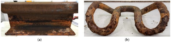
Figure 2.
Exemplified condition of (a) rail sample and (b) fastening clip at the end of the laboratory corrosion test [28].
A track corrosion survey in subway tunnels was carried out and analyzed in [30], where corrosion severity was rated on a numerical scale for rails and components of the fastening system. The presence of stray currents was also evaluated by using the lateral gradient technique (LGT): the potential was measured between the embedded reinforcement and the concrete surface. Corrosion was found to be most severe where the soil had accumulated and bridged the electrical insulation between the rail, or fasteners, and the concrete surface.
In conclusion, corrosion can cause severe degradation of the rails and the fastening system. For this reason, it is essential to immediately prevent corrosion and stray current when building or reconstructing track systems. Some operators have recognized the danger that stray current poses to the infrastructure and, in their guidelines, set out the parameters that must be adhered to in order to reduce and control stray current phenomena and thus extend the service life of the track system.
This work proceeds through existing guidelines and prescriptions in Section 2, notable for its for completeness, adequacy, and effectiveness, and then goes into the details of suggested measures for the design, discussed in Section 3. Section 4 provides recommendations for measures to apply when building tracks with continuously and discretely fastened rails, respectively.
2. Overview of Guidelines and Standards for Stray Current Limitation
The most important measures to reduce stray current on track structures are to increase the track-to-ground resistance (sometimes expressed in terms of conductance ) and reduce the designed longitudinal electrical resistance of the running rails [10,31]. Track-to-ground resistance can also be expressed as rail-to-ground resistance , where [32].
Because of the many different types of track structures, there are no uniform measures to achieve a high value and to prevent stray current. If rails are completely insulated (as in tracks with continuously fastened rails, where elastic material provides continuous rail support and isolation, see Figure 3), stray current is in principle prevented. But in the tracks with discretely laid and fastened rails (shown in Figure 4), it is hard to completely insulate the rail and fastening systems so stray current and consequently corrosion processes are inevitable. When tracks are located in the coastal and marine environment or built on street sections (where salt mix is used to prevent freezing during the winter), these harmful conditions reduce rail-to-ground resistance. Also, sunlight, relative humidity, temperature, and atmosphere largely affect corrosion [23]. Wet conditions are especially pronounced in tunnels and in closed formations.
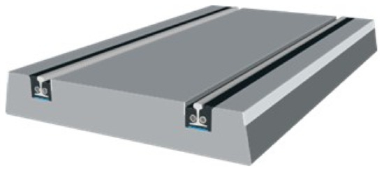
Figure 3.
Track with continuously fastened rails [33].
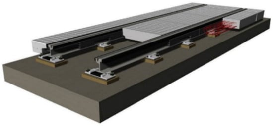
Figure 4.
Tracks with discretely fastened rails [33].
Some operators have defined limit values for and established guidelines on how to achieve and maintain such values. In this section, an analysis of the guidelines applied to different infrastructures is carried out, providing a general overview of the typical requirements.
According to the standard EN 50122-2 [34], the most important parameters for the magnitude of stray currents are:
- The conductance per length of the tracks and the other parts of the return circuit;
- The distance between TPSs;
- The longitudinal resistance of the running rails, when used for the traction return current flow;
- The spacing of cross bonds.
In the EN 50122-2, it is stated that experience has proven that there is no damage in the tracks over a period of 25 years if the average stray current per length does not exceed mA/m of a single track line. According to this standard, if the following values of rail-to-ground conductance per length are not exceeded during system’s lifetime, it is not necessary to conduct further investigations:
- per track and for open track formation;
- per track and for closed track formation.
where indicates the track potential, having subtracted the off potential (usually negligible, as discussed in [35]).
In the design guidelines for the new LRT in Edmonton, Canada [36], in Chapter 13 the designer is required to prepare a stray current mitigation plan and to carry out a stray current survey for the new track construction. The stray current mitigation plan must specify stray current control requirements, identify the infrastructure to be considered in the stray current design, and include verification and validation requirements. The purpose of the stray current survey is to establish a baseline for the prevailing stray current phenomena prior to construction. The primary focus of the stray current design should be mitigating the stray current at the source: where a large cannot be achieved, additional measures to protect adjacent conductive structures must be considered. The suggested measures are the use of high-insulation materials for the track and protective coatings for isolation from the ground for conductive structures as possible victims of stray current.
We can say that high values can be achieved by using high-resistivity ballast materials with adequate drainage; grading; and appropriately designed insulating track fastening devices. An insulating resin bed or an insulating inter-layer between the track and the bearing system, such as a rail boot, must be provided for a closed track. Adequate drainage, both on the surface and in the substructure, is required to avoid water stagnation that could compromise rail insulation.
Also, the guidelines prepared for the Valley Metro project in Arizona [37] include a number of requirements for stray current and corrosion protection: minimum values are indicated for different types of track systems, and they are altogether presented in Table 1 at the end of the section. For ballasted track and direct fixation track construction, the minimum is 500 per 1000 ft ( m) and for the embedded track is 250 per 1000 ft ( m), recognizing as commonplace a larger leakage for embedded tracks laid down with traditional construction systems. However, the guideline requires that all embedded rails must be encased in insulating boots, extended to the top of the concrete on both rail sides to prevent stray currents.
The design criteria for the Central Corridor LRT in Minnesota [38] also address corrosion control measures, clarifying the necessity of control at the source under all normal operating conditions rather than attempting to mitigate the harmful effects on other transit facilities and underground structures. Not only, as is obvious, are direct or indirect electrical connections between the positive and negative traction circuits and the ground forbidden, but TPS separation is also required so that track voltage does not exceed 50 V during normal operation.
This 50 V, in contrast to a commonly accepted 60 V or higher for railway applications [39], was commented on in [40] as commonplace when electrical safety prevails on stray current protection and 50 V is enforced as a safety measure at the workplace, particularly in the US. Limits on track-to-ground voltage are also specified in the standard EN 50122-1 [39], where the allowable values are much higher than traditionally allowed in North America. The higher track-to-ground voltage results in a higher stray current for the same track-to-ground resistance, which must be taken into account when determining limit values for the rail-to-ground resistance.
The level of stray current is also required to be checked by simulation against suitable values, distinguishing the various types of track and rail fixation systems and having determined local soil resistivity values distributed along the alignment (every 500 ft ( m) for the first meters of soil depth). As seen, soil resistivity and corrosivity assessment is a widespread requirement in North America, usually to take at regular intervals along the alignment. Another requested result of the simulations is the expected soil potential gradient values.
The different track construction types have specific requirements: 250 per 1000 ft ( m) for direct fixation track construction and 100 per 1000 ft ( m) for embedded and ballasted track (also reported in Table 1 below). To allow one to reach the necessary values, appropriate insulating track fastening devices should be used, such as insulated sleeper plates, insulated rail clips, direct fasteners, rail boots, or other approved methods.
In [41] it is observed that the degree of insulation between the rails and the ground is necessarily a compromise between the need to control step and touch voltages and the need to limit stray current leakage. The guideline also draws attention to the critical environmental conditions of Dubai, in particular sandstorms and sand accumulation, the extremely high level of humidity (especially during the night and early morning), and the high intensity of the solar radiation (with negative impact on insulating materials). An overview of all elements characterizes the guideline, including traction negative cables, specified as double-insulated, non-screened, non-armored, and to be routed in non-conductive trunking and ducts.
The isolation level between the ground and the rails is required to be above the minimum criteria of 10 km for the tunnel and 2 km for the open area of a single-track section under normal operating conditions (which is not different from the prescribed limits in the EN 50122-2 [34], also using the same expression of “over system’s life”). The target value for a newly commissioned track is 100 km, providing a minimum tenfold margin on the hard limits.
In addition, these guidelines consider an overall approach for stray current protection and monitoring at the track, including at least the following:
- The isolation or control of all possible stray current leakage paths to minimize stray current effect on the system and adjacent structures;
- The detection and monitoring of stray currents;
- The stray current collection system (that in [12] is separated in “capturing sections” for the conductive parts beneath the running rails and “collection sections” for the longitudinal interconnecting conductors).
Stray current monitoring stations are specifically required in [38] at electrical discontinuity points (implied “of the rails”) and at intermediate points but in general not farther than 152 m which represents quite a demanding density of testing points). Test points are also required for the stray current collection system junction points, which are also specified not to be separated by more than 305 m.
The stray current capturing system is required to be implemented with longitudinal reinforcement elements to enable electrically continuous welding, which is a debated point as some administrations discourage it to avoid the risk of cracks. Wire ties, however, do not ensure a low resistivity path for an efficient stray current capture. On this, it may be observed that providing additional rebars without reinforcing function would remove all doubts on welding durability. It is also underlined that welding is also prescribed by CENELEC (and IEC) for reinforcement with lightning protection function in buildings with no negative outcomes so far [42].
The stray current management guide [43] provided by UK Tram (a non-profit association of tramways, metros, and other similar mass transit systems of the former Great Britain) remains on the same lines indicating good track insulation and low track voltage as the two key factors to reduce stray current. The former can be achieved by frequent feeding points, reducing TPS separation and the distance over which the return current must flow. However, reducing TPS separation entails a significant financial impact.
Rails should be continuously welded, and frequent cross-bonding between rails should be provided to ensure multiple parallel paths for the return current; the maximum availability of return conductor capacity; and redundancy in case of a failed bond or of rail discontinuity.
The general prescription for the advisable separation of rail-to-rail and track-to-track bonding points is 200 m and 400 m, respectively, and this aspect will be discussed later in Section 3.5. The actual adequate spacing for each type of bond should be an outcome of a rail potential study and must be determined during the design phase of the track construction.
Also, NASA and the US Department of Transportation [44] considered the problem of stray current and its control almost 50 years ago, focusing in particular on preventing the worsening of stray current levels in older systems, when stray current control was not part of the design. The suggested approach is first and foremost to clean and maintain the track and to monitor its conditions:
- Special attention should be paid to track cleanliness: debris and dirt should not be allowed to accumulate on the track;
- Any corrosion damage should be investigated immediately, by measuring local stray current and measures should be taken to control it;
- Several maintenance procedures should be followed: tests should be carried out in cooperation with third parties (e.g., utilities and structures owners) to ascertain undue impact on underground metallic structures.
Tests were prescribed to be conducted with owners of third-party structures to ensure that operation of the transit system does not affect potentially exposed underground conductive structures. The structure’s impressed potential should be observed to evaluate stray current conditions and the effectiveness of cathodic protection systems. However, no clear prescription with limits or reference levels was given, and this is a general weak point of corrosive situation assessment: the limit values in fact depend on the type of soil, the environmental conditions, and the type of metal the structure is made of.

Table 1.
Allowed values of track-to-ground resistance in in the reviewed guidelines.
Table 1.
Allowed values of track-to-ground resistance in in the reviewed guidelines.
| Type of the Track Construction | Valley Metro, Phoenix, AZ ([37], Section 9.5) | Central Corridor LRT, Minneapolis, MN ([38], Section 14) | Dubai Metro, UAE ([41], Appendix 1) |
|---|---|---|---|
| Ballasted track | 152.4 | 30.5 | – |
| Embedded track | 76.2 | 30.5 | – |
| Direct fixation track | 152.4 | 76.2 | – |
| All tracks | – | – | 100 |
| Track in tunnel (hard limit) | – | – | 10 |
| Track in open area (hard limit) | – | – | 2 |
A direct comparison of prescriptions shows that the three systems have almost similar requirements, with a 2.5 span, but a different viewpoint with respect to track construction type may be identified, with Phoenix and Minneapolis differing significantly for ballasted tracks.
3. Measures for Reducing Stray Current When Designing New Track Corridors
When designing new track corridors in urban areas or when the track reconstruction is planned, stray current prevention should be anticipated. When determining corridors for new tracks, consideration must also be given to the location of existing buried metallic infrastructures that could be affected by stray currents.
Let us suppose that a victim pipeline is laid parallel to planned track construction: in this case, the severity of stray current will depend on the distance between the pipeline and the track because the electrical resistance of the soil through which the current flows increases with distance. Soil in general is not uniform, and resistivity may vary significantly, so that confirmation from a geological survey is welcome; in urbanized areas, the phenomena are exacerbated in the presence of buried conductive structures.
If the pipeline is laid perpendicular to the planned track, the stray current severity is determined by the smallest distance between the pipeline and the track, which is analyzed in [18]. In this case, the area of contact is limited and stray current coupling limitation relies more on local provisions, such as the use of drainage bond, additional insulating layers beneath the track, and an increase in rail insulation.
Due to limited space and many underground infrastructures, it is almost impossible to define a new corridor for track construction in such a way that stray currents do not endanger nearby metallic structures, so limit values must be identified to monitor during construction and commissioning. The amount of track leakage current and the way it is distributed at the interface between the rails and infrastructure highly depend on the construction technique, the interfacing elements, and suitable isolation techniques, such as non-conductive pads and bituminous layers [12], which are defined by the type of the track.
Location and environment also affect the intensity of the stray current. For example, if the tracks are located in a marine environment, the presence of chlorides reduces rail-to-ground resistance but also increases the exposure to and rate of corrosion of reinforcement in concrete. Tracks built on street sections are also exposed to salts, which are used in the winter months to prevent the pavement from freezing. Since closed tracks dry very slowly, the track is wet most of the year, resulting in lower electrical resistance values, which also applies to tracks located in tunnels, subways, etc. These are the main reasons why it is not possible to specify a uniform limit value of track-to-ground resistance to prevent stray currents. Furthermore, due to many influencing factors, will largely vary seasonally and during the service life of the track.
3.1. Types of the Track and Electrical Resistance of Fastening Systems
When choosing the type of track, should be one of the parameters driving the technical assessment. Different methods can be used for the different types of tracks to prevent stray currents and achieve high values. Tracks, as regards fastening, can be divided into two groups:
- Tracks with continuously fastened rails;
- Tracks with discretely fastened rails.
The main difference between the two is that in tracks with continuously fastened rails, rails are placed in paved slabs and supported continuously by an elastic compound. In contrast, in tracks with discretely fastened rails, rails are fastened at regular intervals using different types of fastening systems [45].
In tracks with continuously fastened rails, the rail is laid in a longitudinal recess created in the base structure and poured out with elastic embedding material. Rail fastening is realized by the contact of the embedding material with the rail and the recessed surface, which ensures the complete insulation of the rail and a high value of [46].
In tracks with discretely fastened rails, more attention should be paid to , especially when the tracks are built on street sections. In this type of track, the rails are not completely isolated, and many parameters affect values. The most important parameters are the type of fastening systems, whether the track is open or closed, the maintenance of the track, and the distance between the rail and the adjacent metallic parts.
During the service life of the track, the most important factor is keeping the track dry and well-drained to prevent contact between the rails and the electrolyte, i.e., the water that remains in the track. During track construction, anchor bolts cannot cut the reinforcement bar or be in contact with the reinforcement bar in the concrete base slab [47]. When effective drainage is provided in tracks with discretely fastened rails and the rails are not in contact with the electrolyte, each fastening system provides a spot resistance to ground [48], so by using the appropriate type of the fastening system, values can be increased. The electrical resistance of five different types of fastening systems on concrete base is analyzed in paper [49]. The results show that the electrical resistance of indirect fastening systems is significantly higher than resistance of direct systems, with an incomparably higher electrical resistance value found in the sample of continuously fastened rail (Figure 5).
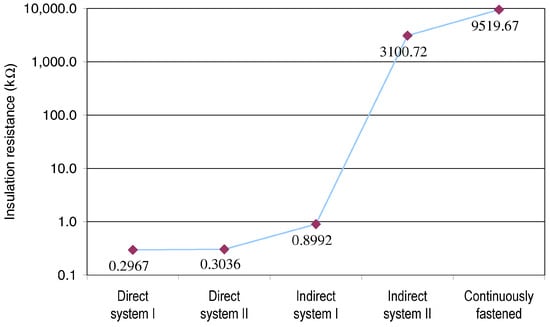
Figure 5.
Electrical insulation resistance of different types of fastening systems [49].
These direct and indirect fastening systems are characteristic of tracks with discretely fastened rails, in which the rail is supported by an elastomer pad (rail pad) on a steel base plate laid on a concrete base. In direct systems, the rail is fastened with clips and anchor bolts. The anchor bolts provide anchorage of the fastening system in the concrete base (Figure 6). In the indirect systems, the rail is fastened to the steel plate by means of clips and T-bolts, and the anchor bolts are separate and serve only to anchor the steel plates in the concrete base (Figure 6). In the direct fastening system, all elements are in direct contact and the clip is in contact with the rail, which is why the current flows from the rail into the concrete base. In indirect fastening systems, higher electrical resistance is achieved by insulating the anchor bolts from the steel base plate.
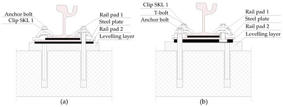
Figure 6.
Cross section of direct (a) and indirect (b) fastening systems characteristic of tram track infrastructure in the city of Zagreb.
A good practice example of an isolated fastening system is the Zagreb 21-CTT indirect fastening system, which was developed for the tram infrastructure in the city of Zagreb (Figure 7). In this system, special care was taken to prevent contact between the steel base plate and the anchor bolt, which was ensured by vulcanizing the steel base plate and designing a special elastomer pad for the anchor bolt, whereby the elastic material used for vulcanizing the plate and manufacturing the pad had to meet high values of electrical resistance. In the laboratory measurements of the electrical resistance of the fastening system on a concrete base, the electrical resistance was more than k [50].
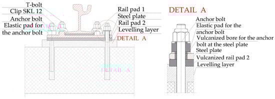
Figure 7.
Zagreb 21 CTT fastening system, an insulated indirect fastening system designed for tram track infrastructure in the city of Zagreb [28].
Based on the results presented in [49], it can be concluded that in order to prevent stray currents, it is necessary that the metallic components of the fastening systems are not in direct contact with the rail, to prevent current leakage through the fasteners into the track base. This can be achieved by the use of insulating pads between the rail and the clip or by preventing contact between the fastening system components and the track base, i.e., by insulating the anchor bolts in indirect fastening systems like in the Zagreb 21 CTT fastening system. The value of the electrical resistance of the elastomer elements must also be specified as it may vary greatly depending on the additives added to the raw rubber during the vulcanization process. Two types of elastomers are generally used for slab track systems: rubber compounds and chloroprene [47].
Speaking of volume resistivity specification for the elastomer elements, with a requirement of > in ( m) fastener stiffness would be compromised. The upper electrical resistance limit of compounds containing carbon black is in ( m). Compounds containing carbon black must be avoided if very high resistance is required, and, in this case, silicone elastomers would have the required electrical insulation performance but poor stiffness properties [47].
If the fastening system selected for the new or reconstructed track does not have a specified electrical resistance value, it is recommended to carry out some laboratory measurements. A laboratory test method for determining the electrical resistance under wet conditions between a running rail with its fastening system anchored to a concrete sleeper is described in the standard EN 13146-5 [51]. The application of such a laboratory test method to determine the electrical resistance of fastening systems used in urban railway tracks is described in [49].
According to [47], the minimum resistance of one fastener at 500 Vdc shall be 10 M when dry and 1 M when wet. According to [49], the insulation values as shown in Figure 5, which are variable below and above the 1 M reference values, are determined by the straightforward application of Ohm’s law for monitored samples under various wet conditions.
3.2. Track Bed Design
As seen, the running rails and the fastening systems are the first and most important elements of the train supporting structure that ensure stray current control if the insulation level is adequate. If rails are not properly insulated (e.g., when structural robustness exigencies prevail or for a matter of reasoned cost containment), the electrical resistance of the track bed has a greater influence on stray current. In [52], it is stated that the resistivity of the material the rail is laid on does not have an effect on the stray current leakage density until the rail coating resistivity drops significantly lower than 100 k m. The determination of a threshold value is not reasonably accurate in view of the variability of the various parameters and environmental conditions: a strong influence comes from the expected resistance of the track bed that in turn depends on the construction technique, and in particular on the use of structural reinforcement and waterproofing membranes.
Designing the track bed with proper insulation layers can isolate the track from the ground. This prevents the flow of stray currents into the ground, minimizing their impact on nearby structures or underground utilities.
In slab tracks, rail-to-ground resistance can be increased by using concrete with a higher electrical resistivity. The electrical resistivity of concrete can vary greatly and depends on the moisture content, temperature, and concentration of salts dissolved in the water that remains trapped in the cement pores [53]. In [54], an analysis of various parameters of slab track concrete was studied, and it was found that reducing the water-binder ratio, adding mineral admixtures, and limiting the air content are important engineering approaches to provide concrete with higher electrical resistivity. The research came with advisable reference values: the water-binder ratio of slab track concrete should be less than 0.31, the air content should be less than 4 %, and the mineral admixtures used in the concrete should have low electrical conductivity.
Care should be taken to ensure that the track bed has an effective drainage system to prevent the accumulation of water and moisture. Water can increase the conductivity of the track bed, increasing the likelihood of stray current of relevant intensity. Proper drainage helps minimize the risk of stray current corrosion: suitable cant, compatible with train stability, ensures that water drains away from the fastener.
Insulating elements, such as rubber mats or other synthetic materials, can be used to create a barrier that restricts stray currents from leaking through the track bed. Such elements are usually used for other reasons than simply electrical insulation, such as water tightness and vibration damping (the latter is quite commonly used to reduce the impact of the transportation system in a densely urbanized context). More specifically, insulating mats under the concrete base in the slab track can reduce the stray current on the rest of the system and third parties, as well as waterproofing membranes surrounding an entire excavated or bored tunnel. Sleeper pads and ballast pads can also increase values and reduce stray current in ballasted tracks.
3.3. Traction Power Station (TPS) Separation
A shorter TPS separation reduces the length of the positive and negative circuits, providing supply to the running trains, reducing the voltage drop in the rails and the amount of stray current [55]. TPSs are usually located near a passenger station, which provides an additional advantage in terms of reducing stray current because the current demand of trains is highest during acceleration, while keeping the voltage drop in the return circuit low due to the short track length [52,55].
Distributing the TPSs more closely along the line increases the number of TPSs for which the cost is not determined by the deployed power (a larger number of smaller TPSs), but by a range of electrical and non-electrical factors: a TPS requires circuit breakers, switches, monitoring, and control whatever its size, so that, simply speaking, a 1 or 2 MW rectifier group has almost the same impact on the overall cost; in addition, the construction of a TPS requires road access, appropriation costs, and the availability of a medium voltage feeding point [10]. In urban areas, available space is often limited, making it challenging to position and build TPSs [56]. Thus, TPS separation is subject to trade-offs, bringing the optimized span at about 2 km to 5 km for urban and metro systems.
The construction and maintenance of TPSs can cause disruptions to the urban transportation network. The TPS location should be carefully planned to minimize impacts on road traffic flow and to provide convenient access for maintenance and emergency personnel. This consideration is particularly important in areas with high commuter volumes and complex transportation networks [57].
Junctions with branched lines, as well as multiple tracks, typically require more installed power compared to straight sections and have a more complex power distribution diagram, including additional circuit breakers and disconnectors. The coordination of protections as well is more complex in terms of selectivity and switch on/off and isolation maneuvers. In general, in such cases longer feeding lines are necessary, increasing voltage drops, both for the catenary/third rail system (lower available voltage) and for the return circuit (higher track potential and lower available voltage).
3.4. Traction Return Grounding Scheme
When selecting and designing the grounding schemes for a DC transit system, a number of factors must be taken into consideration [58], mainly electrical safety for touch voltage and the minimization of stray current. Although an ungrounded solution minimizes stray current, grounding should be provided to keep track voltage under control and prevent high voltage potential that may be hazardous to personnel and equipment safety [59,60].
The grounding schemes for DC transit systems mainly include the solidly grounded scheme, floating scheme, diode grounded scheme, contactor/switch grounding, or thyristor grounding [10,60,61,62]. Such grounding schemes are schematically shown in Figure 8.
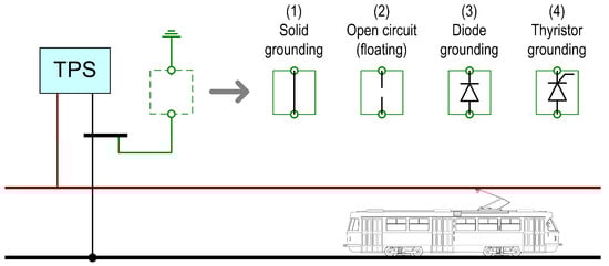
Figure 8.
Grounding schemes of DC railways: (1) solidly grounded scheme, (2) floating scheme (open circuit), (3) diode-grounded scheme, and (4) thyristor-grounded scheme.
More specifically the four introduced schemes can be described as follows:
- In the solidly grounded scheme, the TPS negatives are grounded without interposed impedance to ensure the zero potential of the TPS and to meet safety requirements. This scheme permits stray currents to flow unregulated between the negative bus of the TPS and any underground metallic path in the vicinity [52,63]. In addition, large currents may flow through the rails between different TPSs due to the unavoidable ground potential differences, as caused, for example, by using different utility medium voltage feeding points.
- In the floating scheme, the TPS negatives are not connected to ground, reducing stray current but increasing the rail potential at the TPS and elsewhere. As is known, at the trains locations the track potential will be maximum [64]. Such potentials may result in a hazard for passengers, so providing a protective mechanism is essential for safety reasons. The permissible touch voltage levels are indicated first of all in the EN 50122-1 [39], which allows a variable threshold depending on duration but may be subject to additional local regulations (such as a constant 60 V or 50 V independent of the time factor), as discussed in [40]. A compromise is usually achieved by setting active voltage limiting devices (VLDs), as described below.
- In diode and thyristor grounding schemes, the connections between the negative terminal of the TPS and ground are made by diodes (or thyristors). When the diodes or thyristors are on, the diode and thyristor grounding schemes are the same as the solidly grounded scheme (for current flowing into the negative terminal); otherwise, they are the floating grounded scheme. The diode and thyristor grounding schemes can therefore be considered a combination of the grounded and floating schemes [60,63] or, in other words, a selective grounding scheme only for positive track potential. Stray current collection mats located at regular intervals under the tracks are also connected with a diode through the longitudinal stray current collection cable [10].
The risk of dangerous electrical potentials in ideally ungrounded schemes can be reduced by using VLDs, also named overvoltage protecting devices (OVPDs), and stray current drainage devices (DD) [6,13,52,65]. VLDs are usually installed at the TPS and at passenger stations, distinguishing between type F and type O devices, the former being able to withstand short-circuit fault situations [55]. A VLD is an active device with different design principles depending on the current it must withstand in normal and fault conditions and whether it is associated with lighting surge protection function (hence the term OVPD is more appropriate to describe it). It can be built on a semiconductor device of the thyristor type or still based on electro-mechanical units for heavy use.
If the rail potential exceeds a prescribed limit, the VLD goes in short-circuit state and connects the protected conductive part (e.g., the running rails themselves) to the ground, reducing the potential. In this situation, the DD is activated to drain the current in the stray current collection mats back to the TPS [6,13]. VLDs have a high-impedance state in normal conditions, providing an ungrounded system, thus minimizing stray current and preventing long-term corrosion on third party infrastructure as well [13].
Since the objective of VLDs is to control (and reduce) the track potential to ground and that potential is caused by the traction return current flow, another solution is to drain the return current on an auxiliary conductor. The most obvious and straightforward solution is to run large insulated conductors in parallel to the running rails, possibly interconnecting intermediate points between TPSs directly to the negative terminals of the TPSs themselves, as it is done for the positive feeding points (see Figure 9). The required cross section is evidently large as it should be comparable to that of the running rails themselves, which means approximately more than 1000 mm2 of copper for each track.
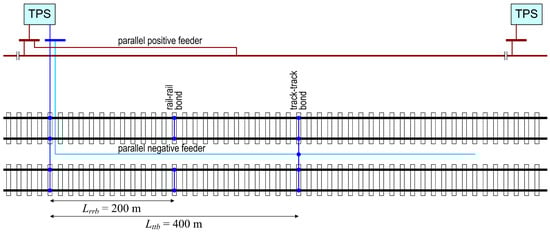
Figure 9.
Arrangement of additional feeding conductors and track cross-bonding.
The DCAT (DC AutoTransformer) system proposed in [60] is effective at driving away from the running rails the current returned by the train (which is always and only in contact with the running rails through its wheels) as soon as that return current reaches one of the DCAT devices distributed along the line. Since the only relevant voltage drop becomes the one for the section between two DCATs where a train is located, the overall longitudinal voltage drop along the whole length between two TPSs is reduced: the larger the number of DCATs, the lower the resulting voltage drop. The connection scheme is shown in Figure 10a.
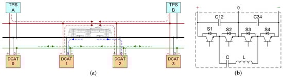
Figure 10.
DCAT system: (a) scheme of deployment and operation (exemplified vehicle in intermediate section between DCAT-1 and DCAT-2; see [60] for a complete description), (b) scheme of DCAT device.
The DCAT operation is based on a three-terminal device connecting the catenary (plus terminal), the negative external return conductor (minus terminal), and keeping the track at a nearly zero potential (zero terminal). The balancing is achieved by an active semiconductor-based balancing bridge with a resonant circuit (shown in Figure 10b), as used for DC link balancing in multi-level converters [66], achieving the soft switching operation.
3.5. Rail/Track Cross Bonding
In transit systems with large return current intensity, it is common practice for the rails of each track to be bonded together and for the tracks to be cross bonded to balance the traction return current, to reduce the resistance of the return path as well as to decrease the track potential and reduce the generation of stray current [67]. As an additional positive effect, the reduction in the return path resistance and the possibility of recirculate current between different tracks at intermediate points between TPSs and not only at TPSs contribute positively to energy efficiency, improving the exchange of regenerative braking energy (improving system receptivity) [68].
Cross bonding is achieved by deploying short-circuiting cable connections between the rails of the same track or of adjacent tracks at regular intervals (using standardized terminals, such as those manufactured by Cembre): connection sizing is such to withstand the normal current flowing under the most unfavorable unbalance conditions, as well as short circuit current scenarios, creating thus a low-resistance path for electrical current [19,43]. Experience has shown that a bond separation of around 200 m is appropriate for rails in a track and that approximately 400 m are appropriate for track-to-track bonds. However, such distance values depend on many factors, such as headway, TPS separation, traction load, and others [55], so that for other systems larger separation may be effective as well. The goal is in fact to keep track voltage to safe voltage values [39], in particular for the interface to standing passengers in front of PSDs [40], besides a general concern for touch voltage. This is normally demonstrated by electromechanical simulations, focusing in particular on areas where access is not restricted during service, such as platforms and the PSD area in particular. Stray current reduction comes as added value, although—-we must underline —it is rarely specified as a contractual requirement specifically with respect to rail bonding, although it is known to prevent the formation of potential differences and reduces the risk of stray currents [69].
So far, practical issues and non-stray-current-related constraints have not been considered. The short-circuit bond of running rails and adjacent tracks has a significant impact on signaling circuits of the track circuit type, for which their operation could be compromised, not to mention the existence of parallel electrical paths shunting the incoming train axles and the compromise of the detection of track integrity. In general, cross bonds and track circuits are not compatible and cannot be used in the same system. Another practical issue is theft, which not only has the obvious impact of economic loss but compromises the infrastructure, requiring more frequent track walks for verification and maintenance. For this reason, many countries use aluminum, steel, or copper-steel mixtures instead of pure copper.
3.6. Drainage Bond
A drainage bond is a conductive bond through an insulated cable between the rail and buried pipeline that provides an alternative path for the current to return to the rail (Figure 11). The aim of drainage bonds is to shift down the potential of anodic areas and thus prevent harmful stray current corrosion on pipelines and other conductive parts in contact with soil [70].
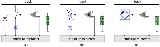
Figure 11.
Drainage bond between the structure to protect and the track: (a) common implementation by unidirectional breaker (with diode) or controlled diode (thyristor), (b) scheme with controllable resistor reported in [70]), and (c) forced drainage by means of a controlled rectifier.
The drainage bond connection should be made at the points where the rail and the pipeline cross or are parallel but very close to each other. The place where the drainage bond is installed should also be suitable for the control of the equipment and located so that it does not interfere with traffic [70].
Direct, polarized, and forced drainage bond methods can be used to mitigate the stray current corrosion on pipelines [71]: the former two may be described as passive methods, whereas the latter is an active one. The principle is to connect the pipeline to the rail by an electrical connection and discharge the stray current either by means of an applied voltage (provided by an external, possibly regulated, voltage source, such as a controlled rectifier) or by the voltage difference normally existing between the pipeline and the rails.
A direct drainage bond between the threatened structure and a reference point that is electronegative enough aims to shift the potential of the anodic area downward, but this solution transfers the corrosion risk to the second structure, which may require further mitigation [72]. The direction of flow is disciplined to occur in one selected direction only by the use of a series-connected diode, realizing the so-called polarized drainage.
When using a polarized drainage system, stray currents cannot leave the protected structure through the electrolyte. The negative pole of the TPS is usually electronegative enough to effectively lower the potential of the protected structure, except for short periods of time (e.g., the moment a train passes the substation) [72]. During these short periods, the series diode ensures that no stray current can flow in the reverse direction toward the protected structure.
In Figure 11, various controlled solutions are shown implementing active protection, triggered by the appearance of dangerous potentials on the structure and measured by means of the triangular block that implements all necessary logic, such as comparison with a threshold, including an offset, hysteresis, and noise rejection. Whereas Figure 11b is an ideal implementation that works in principle, the most commonly adopted methods are Figure 11a,c, corresponding to polarized and forced drainage.
However, some European track operators do not recommend drainage-bond mitigation techniques because it is noticed that drainage bonds can increase the overall leakage of the stray current and increase the corrosion rate of the running rails [19,73]. According to [1], the installation of drainage bonds was recognized only as a supplemental or temporary measure because drainage bonds increase the overall amount and magnitude of stray current, representing an additional low-resistance path connected to the track.
3.7. Stray Current Collection System (SCCS)
During track construction, SCCS can be constructed under the rails to “capture” the stray current that leaks from the running rails and avoid damage to the segments [9,74]. Such collection systems usually take the form of added conductors (such as rebars themselves or welded meshes) in the concrete track bed of a traction system [14,55,75]. If rail insulation and power-system design cannot keep stray current levels below “damage-causing” levels, an SCCS should be provided when building new tracks or rebuilding existing tracks [32]. If an SCCS does not exist, stray current will leak directly into the ground and the rest of infrastructure. A stray current collection system is also useful in the extreme case of local insulation deterioration due to the failure of some of the track elements, providing temporary protection whilst the failure is located and repaired.
This system ensures a low-resistance shunting path for the stray current, thus avoiding possible interference with third-party infrastructure [9]. An important point is that these elements must be insulated from the remaining reinforcement of the track bed and, at the same time, have a good electrical interface with the leaking elements of the track, maximizing the conductive coupling with them [12]. To simplify a bit, the introduction of a stray current capturing element beneath the rails slightly increases the overall rail leakage current as the thickness of insulating concrete is reduced and conductive parts are added.
According to [31], different solutions can be used for the stray current capturing system, such as steel bars placed under the running rails with connections at short separation (50 m is suggested in [31], but longer spans of 100 m to 200 m are commonly used), a copper plate placed under each rail along the entire track, or a mesh of welded smaller steel with a suitable mesh width in the order of 10 cm to 15 cm.
Current designs use an amount of capturing steel from 600 mm2 to 1000 mm2 total cross-section for one rail, in the order of 1/8 to 1/10 of the rail cross-section (for a UIC 60, the cross-sectional area is 7660 mm2, and for gauges 54 and 49, it is slightly but not proportionally less). Construction steel usually has an electrical resistivity that is 13–14 times higher than copper. As the mechanical properties of these capturing rebars are of secondary importance, selecting steel with lower electrical resistivity like low-grade carbon steel may be an option. However, resistance to corrosion is poor, and tests with various chloride concentrations in concrete have shown that the expected life is in the order of 10 years, even for moderate chloride concentrations [12].
3.8. Monitoring and Maintenance during Track Lifetime
Perhaps in the initial stage, the insulating protecting measures are good and ensure high values; the welds between the tracks are not affected by mechanical vibration, corrosion, and dirt; and the longitudinal resistance of the track is low as per design. Therefore, the track potential and stray current are low and do not cause serious corrosion.
However, as the operating time of the track increases, with the influence of moisture and vibration over a long period of time, and with the wear and aging of the insulating materials, the degree of track insulation gradually deteriorates, resulting in an increase in stray current [76]. Such reduced insulation does not correspondingly reduce the track potential, as one may guess by observing that shunts, in principle, the longitudinal track resistance: an estimate was provided in [12,40], where it was simply observed that the order of magnitude is quite different and that the effect of is negligible if values remain in the range of acceptability of EN 50122-2 (the values of some ) compared to the track longitudinal resistance (in the order of 20 m km to 25 m km).
Since the rails serve as current return conductors, any rail breakage that causes an increase in the electrical resistance of the rail must be detected and repaired in a timely manner. Wear of the rail head due to traffic loading also increases the electrical resistance of the rail, resulting in higher stray current values. According to [48], the electrical resistance of the rail can increase by up to 19% due to the wear of the rail head caused by traffic during the service life.
It is important to observe that rails are characterized by an intrinsic variability between samples of the same type, as well as a large increase in electrical resistivity for hardened rails, such as those used at turnouts and at curves [77]. It is thus evident that the overall longitudinal resistance of the track is made of different contributing terms, and, depending on the specific location (straight line, junction with many turnouts, depot or shunting yard) and on the used rail lot, it may vary by 5% to 10%. For such a figure another, 1% to 5% should be considered for the effect of rail welding points [34].
The relationship between the distribution of track potential and the resulting stray current is an important indicator of track insulation. The track potential is affected by the operating conditions of the running vehicles and should always be weighted against the flowing absorbed and regenerated current intensity; in addition, the values should be considered with respect to the local ground potential [12].This is the approach preferentially proposed for stray current monitoring systems (SCMS).
Stray current is not only a dynamic quantity that depends on vehicle traffic and type, and driving mode (accelerating, decelerating, and driving with the same speed), but also on track conditions and soil moisture [33,69]. Some of these parameters affect the rail potential , and others affect the rail-to-ground resistance [69]. Theoretically, it was assumed that is negative at the substation and positive at the point where the current leaks from the rail. In [78], the authors analyzed the rail potential in front of seven substations in urban and suburban areas and concluded that the rail potential can be positive in urban areas and negative in suburban areas. This means that stray current can flow from the rail to the ground in urban areas and flow back to the rail in suburban areas.
There are instead more direct methods to evaluate track insulation, as described in the EN 50122-2 [34], which have been discussed in [8,79,80] and critically reviewed recently in [35]. In synthesis, there are three methods for track insulation determination: voltamperometric measurement on electrically sectioned track sections, similar measurement on electrically continuous tracks estimating and correcting for the rail current leaving the measured section, and lateral electric field measurement (as an estimate of stray current flowing in the soil). The third method is suitable for measurements in traffic conditions, so with the negligible disruption of system operation, the first two require the use of engineering hours at night time. Such methods provide a direct indication of the track insulation level and provide the SCMS with reference information on the health status of the track. Stray current as track leakage current can then be determined by the measured track potential. Alternatively, when a stray current collection system (SCCS) is also provided during system construction, the SCCS collects the stray current collector (SCC) current intensity as an indirect quantification of the track leakage occurring in the collected sections [12].
According to the standard [34], the average measurement period should be 24 h to cover all changes in rail potential during the day: stray current is in fact the highest during rush hours when traffic is intense and track potential is at a maximum [14]. SCMS experience shows that meaningful trends and behaviors are detected only by comparing suitably processed measured data on much longer time intervals, at least to bracket weekly changes (working days and weekends) and to reach statistical consistency.
However, the lack of standardized requirements and technical references results in unclear contractual specifications for the SCMS, without the identification of benchmarks or the formulation of acceptance criteria. The desired performance levels for the acquisition and analysis of electrical quantities are discussed in [12]. In SCMS, track voltage is usually measured and the measurement is implemented at VLDs (as mentioned, located at TPSs and in some cases at all stations) [12,81]. If only TPSs are equipped with track voltage measurement points, not only are they quite sparse (e.g., the above-mentioned 2 km to 5 km range), but the readings are also collected in front of TPSs, where the track voltage change is lowest, and the representativeness and completeness of such monitoring is questionable. If VLDs are placed at all stations, the density of measurement points will increase and track voltage will be monitored approximately every 0.6 km to 1.2 km [12].
If high values of stray current are found from the measured values, a specific inspection and maintenance should be initiated, culminating in more extensive repairs, parts replacement, or even track reconstruction. However, if high is ensured during the construction of the track, the timely maintenance of the track must ensure that stray current values do not increase during operation. Preventive maintenance and track cleaning are the cheapest and most effective measures for the monitoring and prevention of insulation deterioration. More extensive maintenance activities that can also effectively reduce stray currents should include rail replacement due to wear of the rail head, detecting broken rails, maintaining ballast on ballasted tracks to ensure effective drainage, and keeping effective drainage on the tracks built on street sections.
4. Discussion of the Various Approaches
The measures that should be anticipated at the design stage to prevent stray currents in track construction depend primarily on the type of track. For example, in the case of tracks with continuously fastened rails, a high value is ensured so it is not necessary to take care of the electrical resistance of the concrete base. When anticipating the measure to reduce stray current, care must also be taken to ensure that the measure applied does not interfere with the other characteristics that the track must meet. For example, the application of a floating grounding system will reduce the values of stray currents but may cause the formation of high potential values in the rails, which may be hazardous. Therefore, in these cases, devices such as VLDs must be used to prevent high potential values. In addition, for fastening systems used on tracks with discretely supported and fastened rails, it is important that the elastomer elements have high electrical resistivity to prevent current from flowing from the rail through the fasteners into the track base and the ground. However, changing the composition of the material used in the vulcanization process to achieve high electrical resistance should not result in a loss of other properties that the elastomer elements must have. These are primarily stiffness and damping. To effectively prevent stray currents, several measures described in this paper must be combined during track construction. Track maintenance is also important to ensure a high value during the service life since designing and building track construction is an interdisciplinary project to define the best solution that will meet the required track characteristics collaboration between engineers from different fields is necessary. Figure 12 contains recommendations for reducing stray currents depending on the type of track construction, in tracks with continuously fastened rails, where a high value is ensured, and in tracks with discretely fastened rails, where the value depends on the type of fastening system.
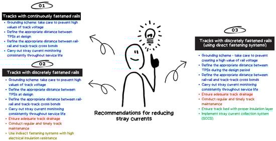
Figure 12.
Recommendations for reducing stray currents depending on the type of track construction.
In tracks with continuously fastened rails, the rails are laid in the grooves of the precast concrete slab, and the free space between the rail and the slab is filled with an elastic material that provides continuous support for the rails (see Figure 3). Since the electrical resistivity of elastic material is very high, it also serves as rail insulation, so in this type of track a high value is achieved and stray currents are prevented.
In discretely fastened rails, stray current can also be reduced, but it is extremely important to pay more attention to regular and timely track maintenance to maintain a well-designed drainage system throughout the service life of the track, especially for tracks built on a street section (where road and rail vehicles share the same driving surface). Maintenance does not need to be performed cyclically at specific intervals but as needed depending on the condition of the track. In the case of tracks with discretely fastened rails located in a separate corridor and closed with different materials, such as crusted stone, this material should be replaced when a high level of dirt and small particles is detected since the presence of dirt and small particles, which is very common near passenger stations, leads to water retention and the prolonged drying of the tracks. Since recommendation No. 3 allows stray current to leak from the rail through the fastening system into the track substructure due to the poor insulation of the rail and fastening system, SCCS should be used to “capture“ the current flowing off the rails. It can be concluded that a combination of different measures, regardless of the type of track, can achieve satisfactory results in preventing stray currents. However, for recommendations No. 2 and No. 3, it is extremely important to pay more attention to track maintenance to preserve track characteristics, especially to maintain the high efficiency of the drainage system.
A comparison of discussed and suggested measures in terms of their construction cost, maintenance, effectiveness in protecting against stray current corrosion on rails and adjacent metallic infrastructure, and durability is provided in Table 2 and Figure 13. Proposed measures are rated from 1 to 5 plus symbols +, where more plus symbols means higher construction and maintenance costs, better properties in terms of protection of tracks and nearby structures, and greater durability. The best result to prevent stray currents is achieved by using a track with continuously fastened rails (suitable for tramways, much less for heavier transit systems). However, when considering the cost sheets of some past realizations, it is found that the price per meter for a track with continuously fastened rails is twice as high as the price for a track with discretely supported and fastened rails. In addition, the application of this type of track on an existing track with discretely supported and fastened rails requires complete reconstruction due to the difference in track heights, leading to long-lasting works with very high costs. Another disadvantage of the continuously fastened track is the fact that with this type of track, it is not possible to carry out visual inspections nor to replace a single element, as is the case with tracks with discretely fastened rails, for example, it is not possible to only replace the rails after the wear of the rail head caused by traffic load.
Table 2.
Comparison of recommended measures to prevent stray current, as listed in Figure 12. For cost items, a low number of plus signs means a lower cost.
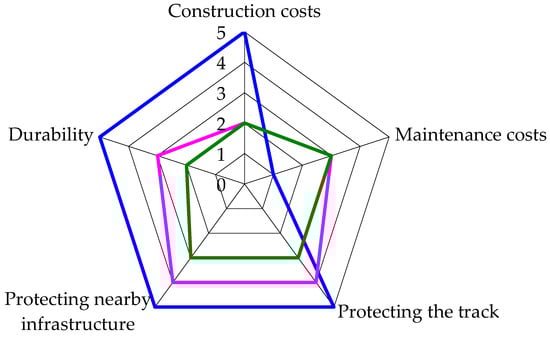
The application of suggested measures No. 1 not only prevents stray currents but also improves other properties of the track, especially with regard to the dynamic effects of vehicles on the track, resulting in the longer life of the track structure and thus lower maintenance costs.
In track construction or reconstruction, recommendations No. 2 and No. 3 result in lower construction costs, but the maintenance of the designed track properties requires higher maintenance costs. In these tracks, the dynamic loads from passing vehicles are much more pronounced than in tracks with continuously fastened rails, so the degradation of the track is much faster, which reduces the life of the track and, consequently, the properties of the track in terms of preventing stray currents.
Indirect fastening systems, which should be used in recommendation No. 2, in most cases have a greater ability to effectively damp rail vibrations induced by passing streetcar vehicles (explained in detail in paper [82]). This results in a longer service life than when a direct fastening system is used.
Good performance in preventing stray currents can be ensured by using tracks with discretely fastened rails, in combination with other methods described in this paper that result in a high value. The methods to be used depend on the type of fastening system and its insulation. Track maintenance is extremely important to ensure the effective drainage of the track during the operating period, especially for closed track formations built on street sections where drainage is shared between the track and the road network. If the track is not adequately drained, the water remaining in the track will lead to a reduction in the value and an increase in stray current levels. Regardless of the type of track construction, the low longitudinal electrical resistance of the rail must be ensured by rail and track cross bonding and by defining appropriate distances between TPSs. These measures also serve to reduce high values of electrical potential in the rail, which can be particularly pronounced in tracks with continuously fastened rails. The value of the potential in the rail is also influenced by the grounding system used.
5. Conclusions
The stray current originating from DC rail traffic causes aggressive corrosion processes on the tracks themselves and on nearby conductive structures. Today, third-party metallic infrastructure located near DC tracks is usually protected to some extent from stray current, such as in the case of the extensively used cathodic protection for pipelines. A better solution is to reduce stray currents at the source, i.e., the track, operating on the traction power supply system.
Some rail infrastructure operators and associations have recognized the harmful effects of stray currents and have specified in their guidelines advised measures and provisions to ensure that stray current impact stays within acceptable limits. However, given the different types of track structures, it is not possible to define measures that are optimized and effective in all cases.
First and foremost, it is necessary to ensure high insulation resistance between the track and the ground (or the supporting structure). This can be achieved by appropriate provisions during the design and construction phases, but it must be ensured that limits are met for the entire operating life of the transit system and that some prescriptions do not cause the deterioration of the other track characteristics. A second useful element of the return circuit design is ensuring the low value of the longitudinal electrical resistance of the running rails, which necessarily must cope with the exigencies of rail steel hardness and must include the contribution of welding points and fish-plates, if any.
Still focusing on the track, other measures extend to stray current capturing and collection by means of an additional circuit of construction rebars and external cables; the former relates to the interference with the reinforcement of the track plinths and track bed. Another solution that has structural relevance is the use of waterproof membranes, with beneficial effects for vibration too.
From a wider perspective, then, the location and optimized separation of TPSs is certainly effective but has much higher costs and constraints, so a wide range of more flexible and cheaper solutions of reduction in track voltage drop may be considered, from cross-bonds to active track potential compensation.
Stray current and corrosion monitoring is thus a precious diagnostic tool, if properly designed and installed, and if one is provided with suitable software for data processing, analysis, and prediction.
With such a complex scenario of different interacting technical elements, the cooperation of engineers from different disciplines is an important factor to find an optimal solution for track during design and construction, and for its interaction with other structures in the vicinity (extended to the entire operating life of the system). In the U.S., most cities that have DC transit systems also have a corrosion coordinating committee (sometimes called an electrolysis committee). This committees hold regular meetings to discuss general stray current conditions. In many cases, utility owners notice a change or increase in stray current activity before the transit agencies notice it. Therefore, the transit system and utility owners must work together to find solutions to unacceptable stray current levels.
This work has reviewed quantitative prescriptions from various guidelines and standards, as well as approaches suggested in the literature and based on experience.
Regardless of the measures taken during the operation, regular maintenance and monitoring of the track is also essential to prevent deterioration and to detect changes, thus supporting monitoring software with direct human input and judgment.
As rail systems become the primary means of transportation in many cities around the world, the demand on track and vehicles to achieve higher transportation capacities and speeds is increasing. As a consequence, a modernization process is on-going that must be accompanied by the update and improvement of guidelines and references used by infrastructure owners and operators, including stray current and corrosion protection as a fundamental factor to preserve an asset’s value and its functional and structural integrity.
Author Contributions
Conceptualization, K.V., S.B., A.M. and R.V.; Methodology, K.V. and A.M.; Investigation, K.V. and S.B.; Writing–Original Draft Preparation, K.V. and A.M.; Writing–Review and Editing, K.V., S.B., A.M. and R.V. All authors have read and agreed to the published version of the manuscript.
Funding
This research received no external funding.
Conflicts of Interest
The authors declare no conflict of interest.
References
- Barlo, T.; Zdunek, A. Stray Current Corrosion in Electrified Rail Systems—Final Report; Technical Report; Northwestern University: Evanston, IL, USA, 1995. [Google Scholar] [CrossRef]
- Shipley, R.W.; Darwin, D.; Locke, C.E.J. Stray Current Corrosion Due to Utility Cathodic Protection; Technical Report; University of Kansas Center for Research, Inc.: Kansas City, KS, USA, 1997. [Google Scholar]
- Popescu, M.; Bitoleanu, A. A Review of the Energy Efficiency Improvement in DC Railway Systems. Energies 2019, 12, 1092. [Google Scholar] [CrossRef]
- Dolara, A.; Leva, S. Calculation of rail internal impedance by using finite elements methods and complex magnetic permeability. Int. J. Veh. Technol. 2009, 2009, 505246. [Google Scholar] [CrossRef]
- Paul, D. DC traction power system grounding. IEEE Trans. Ind. Appl. 2002, 38, 818–824. [Google Scholar] [CrossRef]
- Du, G.; Zhang, D.; Li, G.; Wang, C.; Liu, J. Evaluation of rail potential based on power distribution in DC traction power systems. Energies 2016, 9, 729. [Google Scholar] [CrossRef]
- Dolara, A.; Foiadelli, F.; Leva, S. Stray Current Effects Mitigation in Subway Tunnels. IEEE Trans. Power Deliv. 2012, 27, 2304–2311. [Google Scholar] [CrossRef]
- Bongiorno, J.; Gianoglio, C. Experimental variability of track to ground conductance measurements. J. Phys. Conf. Ser. 2018, 1065, 052015. [Google Scholar] [CrossRef]
- Mariscotti, A.; Reggiani, U.; Ogunsola, A.; Sandrolini, L. Mitigation of electromagnetic interference generated by stray current from a dc rail traction system. In Proceedings of the International Symposium on Electromagnetic Compatibility-EMC EUROPE, Rome, Italy, 17–21 September 2012; IEEE: Piscataway, NJ, USA, 2012; pp. 1–6. [Google Scholar] [CrossRef]
- Alamuti, M.M.; Nouri, H.; Jamali, S. Effects of earthing systems on stray current for corrosion and safety behaviour in practical metro systems. IET Electr. Syst. Transp. 2011, 1, 69–79. [Google Scholar] [CrossRef]
- Brenna, M.; Foiadelli, F.; Zaninelli, D. The Compatibility between DC and AC supply of the Italian railway system. In Proceedings of the 2011 IEEE Power and Energy Society General Meeting, Detroit, MI, USA, 24–28 July 2011; IEEE: Piscataway, NJ, USA, 2011. [Google Scholar] [CrossRef]
- Mariscotti, A. Stray current protection and monitoring systems: Characteristic quantities, assessment of performance and verification. Sensors 2020, 20, 6610. [Google Scholar] [CrossRef]
- Gu, J.; Yang, X.; Zheng, T.Q.; Xia, X.; Zhao, Z.; Chen, M. Rail Potential and Stray Current Mitigation for Urban Rail Transit With Multiple Trains Under Multiple Conditions. IEEE Trans. Transp. Electrif. 2022, 8, 1684–1694. [Google Scholar] [CrossRef]
- Chen, Z.; Koleva, D.; van Breugel, K. A review on stray current-induced steel corrosion in infrastructure. Corros. Rev. 2017, 35, 397–423. [Google Scholar] [CrossRef]
- Zhu, Q.J.; Cao, A.; Wang, Z.F.; Song, J.W.; Chen, S.L. Fundamental Aspects of Stray Current Corrosion on Buried Pipeline. Adv. Mater. Res. 2010, 146, 70–74. [Google Scholar] [CrossRef]
- Chuchit, T.; Kulworawanichpong, T. Stray current assessment for DC transit systems based on modelling of earthing and bonding. Electr. Eng. 2019, 101, 81–90. [Google Scholar] [CrossRef]
- Chen, Z.G.; Qin, C.K.; Zhang, Y.J.; Yang, X.C. Application of a stray current monitoring system base upon virtual instrument. In Proceedings of the 2010 IEEE International Conference on Automation and Logistics, Hong Kong, China, 16–20 August 2010; IEEE: Piscataway, NJ, USA, 2010. [Google Scholar] [CrossRef]
- Allahkaram, S.R.; Isakhani-Zakaria, M.; Derakhshani, M.; Samadian, M.; Sharifi-Rasaey, H.; Razmjoo, A. Investigation on corrosion rate and a novel corrosion criterion for gas pipelines affected by dynamic stray current. J. Nat. Gas Sci. Eng. 2015, 26, 453–460. [Google Scholar] [CrossRef]
- Memon, S.A.; Fromme, P. Stray Current Corrosion and Mitigation: A synopsis of the technical methods used in dc transit systems. IEEE Electrif. Mag. 2014, 2, 22–31. [Google Scholar] [CrossRef]
- Wang, Y.Q.; Li, W.; Yang, X.F.; Ye, G.; Fan, Q.G.; Zhang, L.P. Modeling and simulation the distribution of metro stray current. In Proceedings of the 2010 International Conference on Computer Application and System Modeling (ICCASM 2010), Taiyuan, China, 22–24 October 2010; IEEE: Piscataway, NJ, USA, 2010. [Google Scholar] [CrossRef]
- Ogunsola, A.; Mariscotti, A.; Sandrolini, L. Estimation of Stray Current from a DC-Electrified Railway and Impressed Potential on a Buried Pipe. IEEE Trans. Power Deliv. 2012, 27, 2238–2246. [Google Scholar] [CrossRef]
- Siranec, M.; Regula, M.; Otcenasova, A.; Altus, J. Measurement and analysis of stray currents. In Proceedings of the 2019 20th International Scientific Conference on Electric Power Engineering (EPE), Kouty nad Desnou, Czech Republic, 15–17 May 2019; IEEE: Piscataway, NJ, USA, 2019; pp. 1–6. [Google Scholar] [CrossRef]
- Xu, W.; Zhang, B.; Deng, Y.; Wang, Z.; Jiang, Q.; Yang, L.; Zhang, J. Corrosion of rail tracks and their protection. Corros. Rev. 2021, 39, 1–13. [Google Scholar] [CrossRef]
- Panda, B.; Balasubramaniam, R.; Dwivedi, G. On the corrosion behaviour of novel high carbon rail steels in simulated cyclic wet–dry salt fog conditions. Corros. Sci. 2008, 50, 1684–1692. [Google Scholar] [CrossRef]
- Ferreño, D.; Casado, J.A.; Carrascal, I.A.; Diego, S.; Ruiz, E.; Saiz, M.; Sainz-Aja, J.A.; Cimentada, A.I. Experimental and finite element fatigue assessment of the spring clip of the SKL-1 railway fastening system. Eng. Struct. 2019, 188, 553–563. [Google Scholar] [CrossRef]
- Hernandez, F.R.; Plascencia, G.; Koch, K. Rail base corrosion problem for North American transit systems. Eng. Fail. Anal. 2009, 16, 281–294. [Google Scholar] [CrossRef]
- Safa, M.; Sabet, A.; Ghahremani, K.; Haas, C.; Walbridge, S. Rail corrosion forensics using 3D imaging and finite element analysis. Int. J. Rail Transp. 2015, 3, 164–178. [Google Scholar] [CrossRef]
- Vranešić, K.; Lakušić, S.; Serdar, M. Influence of Stray Current on Fastening System Components in Urban Railway Tracks. Appl. Sci. 2023, 13, 5757. [Google Scholar] [CrossRef]
- Vranešić, K.; Lakušić, S.; Serdar, M.; Alar, V. Detrimental effect of stray current on rails and fastening systems in urban railway tracks. Constr. Build. Mater. 2023, 400, 132645. [Google Scholar] [CrossRef]
- Kurth, J.C.; Krauss, P.D.; McGormley, J.C.; Harper, J. Accelerated Corrosion Study of Direct-Fixation Fasteners. In Proceedings of the CORROSION 2015, Dallas, TX, USA, 15–19 March 2015. [Google Scholar]
- Juybari, E.Z.; Keypour, R.; Niasati, M. Voltage distribution indices method to analyse the performance of various structures of stray current collectors in direct current transit lines. IET Electr. Syst. Transp. 2021, 11, 322–332. [Google Scholar] [CrossRef]
- Cotton, I.; Charalambous, C.A.; Aylott, P.; Ernst, P. Stray current control in DC mass transit systems. IEEE Trans. Veh. Technol. 2005, 54, 722–730. [Google Scholar] [CrossRef]
- Vranesic, K.; Serdar, M.; Lakusic, S.; Kolar, V.; Mariscotti, A. Dynamic Stray Current Measuring Methods in Urban Areas. Balt. J. Road Bridge Eng. 2022, 17, 146–170. [Google Scholar] [CrossRef]
- EN 50122-2; Railway Applications—Fixed Installations—Electrical Safety, Earthing and the Return Circuit. Part 2: Provisions against the Effects of Stray Currents Caused by DC Traction Systems. CENELEC: Brussels, Belgium, 2022.
- Bhagat, S.; Bongiorno, J.; Mariscotti, A. Uncertainty of Standardized Track Insulation Measurement Methods for Stray Current Assessment. Sensors 2023, 23, 5900. [Google Scholar] [CrossRef] [PubMed]
- City of Edmonton. City of Edmonton, High Floor LRT Design Guidelines. 2022. Available online: https://www.edmonton.ca/public-files/assets/document?path=transit/LRTDesignGuidelines.pdf (accessed on 22 May 2023).
- Valley Metro. Valley Metro, LRT Design Criteria Manual. 2020. Available online: https://drupal-space.nyc3.cdn.digitaloceanspaces.com/s3fs-public/uploads/event-resources/valley_metro_design_criteria_may_2020_0.pdf (accessed on 22 May 2023).
- Metropolitan Council. Central Corridor Light Rail Transit, Report for Design Criteria. 2008. Available online: https://metrocouncil.org/Transportation/Publications-And-Resources/Transit/LIGHT-RAIL/Central-Corridor-Light-Rail-Transit-Design-Criteri.aspx (accessed on 22 May 2023).
- EN 50122-1; Railway Applications—Fixed Installations—Electrical Safety, Earthing and the Return Circuit. Part 1: Protective Provisions against Electric Shock. CENELECL: Brussels, Belgium, 2022.
- Mariscotti, A. Electrical Safety and Stray Current Protection With Platform Screen Doors in DC Rapid Transit. IEEE Trans. Transp. Electrif. 2021, 7, 1724–1732. [Google Scholar] [CrossRef]
- Dubai Rail Planning. Guidelines and Design Principles for Railway Projects Undertaken by Developers in the Emirate of Dubai. 2013. Available online: https://www.rta.ae/wps/wcm/connect/rta/ab91274c-2563-4e44-8982-c4d35fdbc8ab/Developer_Guidelines_May_2013.pdf?MOD=AJPERES&useDefaultText=0&useDefaultDesc=0 (accessed on 23 May 2023).
- EN 62305-3; Protection against Lightning—Part 3: Physical Damage to Structures and Life Hazard. CENELEC: Brussels, Belgium, 2011.
- Tramway Technical Guidance Note 3. Design Standards Stray Current Management. 2020. Available online: https://uktram.com/wp-content/uploads/2020/01/DESIGN-STANDARDS-STRAY-CURRENT-MANAGEMENT.pdf (accessed on 24 May 2023).
- NASA and US Department of Transportation. A Corrosion Control Manual for Rail Rapid Transit. 1982. Available online: https://ntrs.nasa.gov/api/citations/19830011617/downloads/19830011617.pdf (accessed on 16 June 2023).
- Ling, L.; Han, J.; Xiao, X.; Jin, X. Dynamic behavior of an embedded rail track coupled with a tram vehicle. J. Vib. Control 2017, 23, 2355–2372. [Google Scholar] [CrossRef]
- Ludvigh, E. Elastic behaviour of continuously embedded rail systems. Period. Polytech. Civ. Eng. 2002, 46, 103–114. [Google Scholar]
- Daniels, L.E. Track-Related Research: Direct-Fixation Track Design Specifications, Research, and Related Material; The National Academies Press: Washington, DC, USA, 2005; Volume 6. [Google Scholar] [CrossRef]
- Charalambous, C.A. Comprehensive modeling to allow informed calculation of DC traction systems stray current levels. IEEE Trans. Veh. Technol. 2017, 66, 9667–9677. [Google Scholar] [CrossRef]
- Vranešić, K.; Haladin, I.; Lakušić, S.; Burnać, K. Convenient Procedure for Measuring the Electrical Resistance of Fastening Systems in Urban Railway Tracks. Energies 2023, 16, 1990. [Google Scholar] [CrossRef]
- Vranesic, K. Impact of Stray Currents on Rail Fastening Components in Urban Areas (In Croatian). Ph.D. Thesis, University of Zagreb, Faculty of Civil Engineering, Zagreb, Croatia, 2022. [Google Scholar]
- EN 13146-5; Railway Applications—Track—Test Methods for Fastening Systems—Part 5: Determination of Electrical Resistance. CEN: Brussels, Belgium, 2012.
- Charalambous, C.A. Stray Current Control and Corrosion for DC Mass Transit Systems. Ph.D. Thesis, The University of Manchester, Manchester, UK, 2005. [Google Scholar]
- Madhavi, T.C.; Annamalai, S. Electrical conductivity of concrete. ARPN J. Eng. Appl. Sci. 2016, 11, 4. [Google Scholar]
- Li, H.; Xie, Y.; Yi, Z.; Tan, Y.; Yang, L.; Lou, L. Electrical resistance of ballastless track concrete used in high-speed railway. In Proceedings of the 2nd International Conference on Microstructural-Related Durability of Cementitious Composites, Amsterdam, The Netherlands, 11–13 April 2012; RILEM Publications SARL: Champs-sur-Marne, France, 2013; pp. 1182–1190. [Google Scholar]
- Bhagat, S.; Yang, X.; Wang, M.; Mariscotti, A. Review and evaluation of stray current mitigation for urban rail transit. Trans. China Electrotech. Soc. 2021, 36, 4851–4863. [Google Scholar] [CrossRef]
- Bartłomiejczyk, M.; Jarzebowicz, L.; Kohout, J. Compensation of Voltage Drops in Trolleybus Supply System Using Battery-Based Buffer Station. Energies 2022, 15, 1629. [Google Scholar] [CrossRef]
- Alnuman, H.; Gladwin, D.; Foster, M. Electrical Modelling of a DC Railway System with Multiple Trains. Energies 2018, 11, 3211. [Google Scholar] [CrossRef]
- Makkieh, A.; Emhemed, A.; Wang, D.; Junyent-Ferre, A.; Burt, G. Investigation of different system earthing schemes for protection of low-voltage DC microgrids. J. Eng. 2019, 2019, 5129–5133. [Google Scholar] [CrossRef]
- Zang, J.; Wang, J.; Zhang, J.; Zhou, J. Overview of grounding schemes for solid-state transformers in distribution networks. IET Gener. Transm. Distrib. 2021, 15, 3081–3099. [Google Scholar] [CrossRef]
- Wang, M.; Yang, X.; Zheng, T.Q.; Ni, M. DC Autotransformer-Based Traction Power Supply for Urban Transit Rail Potential and Stray Current Mitigation. IEEE Trans. Transp. Electrif. 2020, 6, 762–773. [Google Scholar] [CrossRef]
- Pham, K.; Thomas, R.; Stinger, W. Analysis of stray current, track-to-earth potentials and substation negative grounding in DC traction electrification system. In Proceedings of the 2001 IEEE/ASME Joint Railroad Conference (Cat. No.01CH37235), Toronto, ON, Canada, 19 April 2001. [Google Scholar] [CrossRef]
- Wang, C.; Li, W.; Wang, Y.; Xu, S.; Fan, M. Stray Current Distributing Model in the Subway System: A review and outlook. Int. J. Electrochem. Sci. 2018, 13, 1700–1727. [Google Scholar] [CrossRef]
- Aatif, S.; Hu, H.; Rafiq, F.; He, Z. Analysis of rail potential and stray current in MVDC railway electrification system. Railw. Eng. Sci. 2021, 29, 394–407. [Google Scholar] [CrossRef]
- Fichera, F.; Mariscotti, A.; Ogunsola, A. Evaluating stray current from DC electrified transit systems with lumped parameter and multi-layer soil models. In Proceedings of the Eurocon 2013, Zagreb, Croatia, 1–4 July 2013. [Google Scholar] [CrossRef]
- Flounders, E.C., Jr.; Memon, S.A. Stray Current Control of Direct Current-Powered Rail Transit Systems: A Guidebook; The National Academies Press: Washington, DC, USA, 2020. [Google Scholar] [CrossRef]
- Sano, K.; Fujita, H. Voltage-Balancing Circuit Based on a Resonant Switched-Capacitor Converter for Multilevel Inverters. IEEE Trans. Ind. Appl. 2008, 44, 1768–1776. [Google Scholar] [CrossRef]
- Charalambous, C.A.; Cotton, I.; Aylott, P. A simulation tool to predict the impact of soil topologies on coupling between a light rail system and buried third-party infrastructure. IEEE Trans. Veh. Technol. 2008, 57, 1404–1416. [Google Scholar] [CrossRef]
- Bhagat, S.; Bongiorno, J.; Mariscotti, A. Influence of Infrastructure and Operating Conditions on Energy Performance of DC Transit Systems. Energies 2023, 16, 3975. [Google Scholar] [CrossRef]
- Tzeng, Y.S.; Lee, C.H. Analysis of Rail Potential and Stray Currents in a Direct-Current Transit System. IEEE Trans. Power Deliv. 2010, 25, 1516–1525. [Google Scholar] [CrossRef]
- Niasati, M.; Gholami, A. Overview of stray current control in DC railway systems. In Proceedings of the 2008 International Conference on Railway Engineering—Challenges for Railway Transportation in Information Age, Hong Kong, China, 25–28 March 2008; pp. 1–6. [Google Scholar]
- Ha, Y.C.; Kim, D.K.; Bae, J.H. Countermeasures for Electrolytic Corrosion—Part I: Traditional Methods and their Problems. In Proceedings of the EUROCORR 2004: Long Term Prediction & Modelling of Corrosion, Nice, France, 12–16 September 2004; European Federation of Corrosion: Brussels, Belgium, 2004; pp. 1–8. [Google Scholar]
- Mo, S.; Yang, S.; Lu, X.; Zhang, J.; Liu, Y.; Liu, X.; Lai, G. Investigation of Dynamic Stray Current Interference from Direct Current System with City Pipelines. In Proceedings of the ICPTT 2013, Xi’an, China, 16–18 October 2013; American Society of Civil Engineers: Reston, VA, USA, 2013. [Google Scholar] [CrossRef]
- United Kingdom Onshore Pipeline Operators’ Association. D.C. Interference Guidelines UKOPA/GPG/031 Edition C. 2020. Available online: https://www.ukopa.co.uk/wp-content/uploads/2020/12/UKOPA-GPG-031-DC-Interference-Ed-1.pdf (accessed on 11 July 2023).
- Liu, W.; Li, T.; Zheng, J.; Pan, W.; Yin, Y. Evaluation of the Effect of Stray Current Collection System in DC-Electrified Railway System. IEEE Trans. Veh. Technol. 2021, 70, 6542–6553. [Google Scholar] [CrossRef]
- Chen, M.; Yang, X.; Zheng, T.Q.; Zhao, Z.; Xia, X.; Gu, J. Improved control strategy of zero-resistance converter system for rail potential and stray current mitigation. Int. J. Rail Transp. 2022, 11, 248–266. [Google Scholar] [CrossRef]
- Song, C.; Li, Z.; Wang, H.; Liu, X. Analysis of influence law of rail transition resistance on subway stray current. In Proceedings of the 2022 7th Asia Conference on Power and Electrical Engineering (ACPEE), Hangzhou, China, 15–17 April 2022; IEEE: Piscataway, NJ, USA, 2022. [Google Scholar] [CrossRef]
- Mariscotti, A. Impact of rail impedance intrinsic variability on railway system operation, EMC and safety. Int. J. Electr. Comput. Eng. IJECE 2021, 11, 17. [Google Scholar] [CrossRef]
- Ooagu, R.; Taguchi, K.; Yashiro, Y.; Amari, S.; Naito, H.; Hayashiya, H. Measurements and calculations of rail potential in D. C. traction power supply system. In Proceedings of the 2019 11th Asia-Pacific International Conference on Lightning (APL), Hong Kong, China, 12–14 June 2019; IEEE: Piscataway, NJ, USA, 2019. [Google Scholar] [CrossRef]
- Bongiorno, J.; Mariscotti, A. Track insulation verification and measurement. MATEC Web Conf. 2018, 180, 01008. [Google Scholar] [CrossRef]
- Bongiorno, J.; Mariscotti, A. Variability of measured railway track conductance due to test set-up. ACTA IMEKO 2019, 7, 21. [Google Scholar] [CrossRef]
- Kampeerawat, W.; Jongudomkarn, J.; Kirawanich, P.; Sumpavakup, C. Effect of Voltage Limiting Device Operation on Rail Potential and Stray Current in DC Railway Systems. GMSARN Int. J. 2023, 17, 213–219. [Google Scholar]
- Lakušić, S.; Haladin, I.; Ahac, M. The Effect of Rail Fastening System Modifications on Tram Traffic Noise and Vibration. Shock Vib. 2016, 2016, 4671302. [Google Scholar] [CrossRef]


Disclaimer/Publisher’s Note: The statements, opinions and data contained in all publications are solely those of the individual author(s) and contributor(s) and not of MDPI and/or the editor(s). MDPI and/or the editor(s) disclaim responsibility for any injury to people or property resulting from any ideas, methods, instructions or products referred to in the content. |
© 2023 by the authors. Licensee MDPI, Basel, Switzerland. This article is an open access article distributed under the terms and conditions of the Creative Commons Attribution (CC BY) license (https://creativecommons.org/licenses/by/4.0/).