Review

In Situ Combustion: A Comprehensive Review of the Current State of Knowledge

Department of Civil and Environmental Engineering, University of Alberta, Edmonton, AB T6G 2E3, Canada
*
Authors to whom correspondence should be addressed.
Energies 2023, 16(17), 6306; https://doi.org/10.3390/en16176306
Submission received: 29 July 2023 / Revised: 23 August 2023 / Accepted: 29 August 2023 / Published: 30 August 2023
(This article belongs to the Special Issue Enhanced Hydrocarbon Recovery)

Abstract

:
In situ combustion or fire flooding is a promising enhanced oil recovery (EOR) technique designed to produce heavy oils and bitumen. This method involves the in-place heating and combustion of hydrocarbons, resulting in reduced viscosity and increased mobility for improved flow toward the production wellbore. Despite its potential, widespread commercial implementation of in situ combustion has been hindered due to technical and economic challenges like inadequate project design and improper reservoir selection. This literature review paper provides a comprehensive overview of the current knowledge of in situ combustion by addressing its principles, historical development, combustion processes, underlying kinetics, and testing methods. Additionally, the review tackles existing gaps in the literature, as well as the challenges associated with modeling and implementation in field applications. It also suggests solutions drawn from historical field experiences of the technology. Finally, the review paper proposes comprehensive screening guidelines derived from various literature sources for the implementation of in situ combustion. This framework underscores the technique’s potential for efficient and sustainable hydrocarbon extraction, shaping its future as a transformative enhanced oil recovery technology.

1. Introduction

The energy and industrial sectors are turning towards hard-to-reach and non-negligible oil reserves that are essential for future energy supply. This is because conventional oil reserves are being depleted and reaching the end of their commercial life. However, commercial extraction of heavy oil poses significant challenges due to its high viscosity and density, particularly in countries such as Canada and Venezuela, where viscosity values can reach up to 106 cp. The primary challenge is to reduce the oil’s viscosity to facilitate easier production of hydrocarbons. To tackle this challenge, thermal methods like steam injection and in situ combustion are employed as effective solutions [1]. While steam injection may seem feasible, it has significant environmental drawbacks, such as requiring vast amounts of water and energy and generating large amounts of greenhouse gases. In contrast, in situ combustion is a promising and less environmentally harmful solution that ignites a portion of the heavy oil in the reservoir while reducing its viscosity and enabling its easier extraction.
Moore et al. [1] define in situ combustion as “the propagation of a high-temperature front for which the fuel is a coke-like substance laid down by thermal cracking reactions”. In other terms, it is a thermally induced enhanced oil recovery method where the thermal energy is generated in situ, i.e., in place or in the reservoir, by injecting an oxidizing gas (air or oxygen-enriched air) that burns a portion of the heavy oil acting like a fuel, i.e., 5 to 10% of the oil-in-place [2]. Typically, this oil is predominantly composed of heavier components.
The in situ combustion method is known to be the oldest thermal recovery method [3,4] dating back to the early 1920s [5,6,7,8,9,10]. Since then, many projects have been carried out all over the world. The first successful ISC (in situ combustion) project in the U.S. occurred in 1920 in southern Ohio to melt paraffin and increase oil production [11]. Similarly, the first field experiment of in situ combustion outside of the U.S. took place in the Soviet Union in 1935 [12]. In Canada, Lloydminster-type sands in Alberta and Saskatchewan have good features for implementing fire flooding. To date, the most successful project is located in the Suplacu de Barcău field in northwestern Romania and has become the largest of this type in the world [13].
Over the course of implementing in situ combustion, there have been both successful operations and failures resulting from various factors. Despite demonstrating exceptional theoretical thermal recovery efficiency, multiple projects in the 1990s encountered failure. The causes behind these failures include an inadequate selection of reservoirs, unfavorable characteristics of both the reservoir and the fluid, deficient design and operational practices, and unfavorable economic factors [4]. Specifically, in Canada, problems like the lack of control of the operation are attributed to a poor understanding of the main kinetic parameters [1]. This has led to many early failures in field tests (55% of the projects in the USA between 1960 and 1990 failed) [4]. Consequently, the level of interest in ISC has dramatically decreased, which is why operation and production engineers consider it as their last option for oil recovery [14]. Additional factors contribute to this issue, including the substantial investment required to acquire air compressors, the intricate nature of the combustion process, which demands a high level of specialized expertise, and the scarcity of qualified personnel available to tackle this complex task [15].
Notwithstanding, several advantages are associated with this recovery method, including eliminating steam-related costs, a marked reduction in greenhouse gas emissions, avoiding the need for water recycling processes, in situ upgrading of heavy oil, and avoiding energy-intensive methods further down the production chain. Such benefits make this approach both more environmentally sound and economically viable [16,17,18,19,20,21,22,23]. According to Storey et al. [24], ISC can be used to produce more environmentally friendly energy through the in situ production of hydrogen [19,25] and from the naturally high heat flow of ISC via enhanced geothermal systems [26,27,28,29].
All in all, in situ combustion is considered a promising yet complex technique for extracting hard-to-reach oil reserves. While it offers significant potential, its implementation in field projects remains difficult. This literature review paper critically evaluates current knowledge on in situ combustion by focusing on experimental studies, identifying the critical challenges for modeling, and implementation. Through synthesizing the latest research, this paper aims to provide an insight into the most effective approaches for field implementation, outlining the key concepts and methodologies involved. Furthermore, this review identifies existing gaps in current knowledge and highlights areas where further research is needed to fully understand the potential of this technology. In summary, this paper provides a comprehensive analysis of in situ combustion, from kinetic reactions to engineering challenges, and seeks to inform future research and development in the field.

2. Forward and Reverse Combustion

When it comes to enhancing oil recovery, in situ combustion techniques have received significant interest. Three notable methods in this domain are dry forward combustion, wet forward combustion, and reverse combustion. These techniques involve the controlled ignition of oil within the reservoir to improve oil mobility and extraction.
Table 1 provides an overview of the different ISC processes. The remainder of this section briefly overviews these techniques, their advantages and limitations, and a practical understanding of how they contribute to ISC practices.

2.1. Dry Forward Combustion

This technique involves the injection of air into a designated injector well, followed by the ignition of oil either through natural means (autoignition) or with the aid of external heat sources (such as electrical or gas heaters). It is worth noting that the accidental ignition of an oil reservoir was initially observed in the 1920s during an air injection operation for pressure maintenance, leading to the discovery of the conventional in situ combustion EOR method [30].
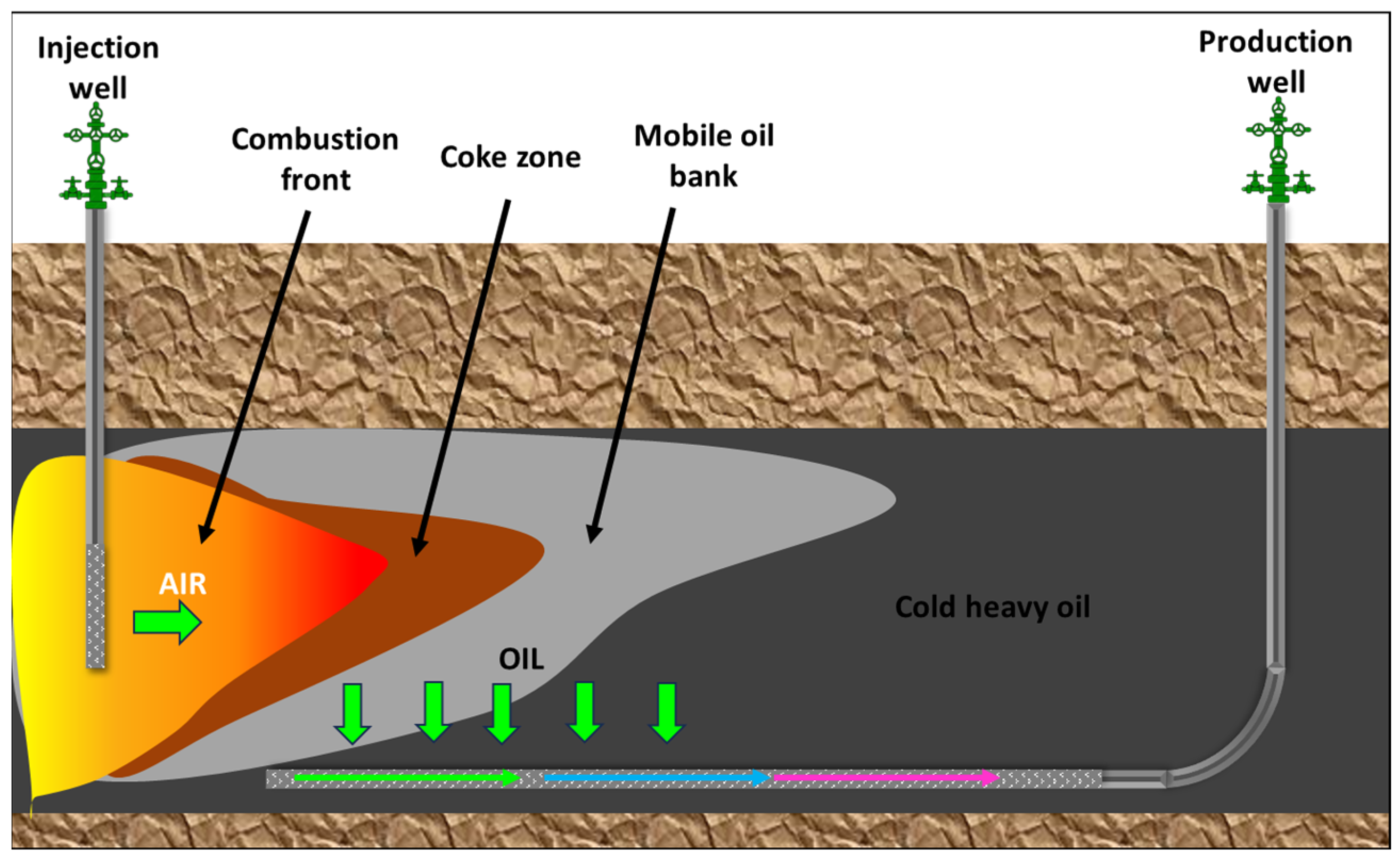
Once the oil ignition occurs, different heat zones are created within the reservoir due to heat and mass transport. These zones give rise to distinct temperature profiles, as illustrated in Figure 1. A combustion front is established among the zones where a portion of the oil (coke) undergoes combustion, generating heat. This heat is then transferred via convection through the water, facilitating oil mobilization. Continuous air injection is employed to sustain the advancement of the combustion front towards the production well, with both the combustion front and the injected air moving in the same direction.
In conventional dry forward combustion, the injection of oxygen (air) into the reservoir serves the purpose of igniting the coke, sustaining the combustion front, and displacing the oil towards the production well. This process can be likened to cigarette burning or the glowing hot zone observed in barbecue coals [3].
Figure 1 is an idealized representation of a dry forward combustion process based on a combustion tube experiment. The zones depicted above move alongside the airflow direction; the exact definition of each of these zones is described elsewhere [4].

2.2. Wet Forward Combustion

In the dry forward combustion mechanism, only oxygen is injected; however, during this process, much of the heat remains in the zone behind the combustion front since the heat capacity of the gas is very low. On the other hand, water can be injected with air to improve the heat transfer forward. To overcome this issue, wet combustion was designed to get some heat to the zone ahead of the combustion front [31].

2.3. Reverse Combustion

Reverse combustion, also called countercurrent ISC, works like a cigarette [31]. The combustion front is initiated near the production well, and the more is blown into the cigarette (into the reservoir), the more the combustion front moves toward the injector well. At the same time, the oil is displaced toward the production well. This results in the air and the combustion front moving in opposite directions.
Although not a very promising technique beyond laboratory tests [4,15,32], this method was proposed for high-viscosity oil and tar reservoirs where the hydrocarbons have to flow from hot to cold regions, resulting in reduced mobility and increased flow restrictions. To address this challenge, the method keeps the major portion of the heat between the production well and the mobilized oil. By doing so, this method enables hydrocarbons to flow more efficiently during production, with minimal heat losses. Nevertheless, according to Brigham et al. [3], there are two main reasons why it has not been successful:
1.
The need for high-cost tubulars that can withstand the high temperatures of the produced fluids. Also, reverse combustion generally requires more oxygen than forward combustion; therefore, the costs will be higher.
2.
Some deposits of unburned heavy hydrocarbons will remain in the reservoir. Eventually, these materials will tend to react, and the process will shift to forward combustion.

3. Other ISC Approaches

3.1. Toe-to-Heel Air Injection (THAI)

THAI is a method of enhanced oil recovery (EOR) that involves injecting oxygen-enriched air into the subsurface at the toe of a horizontal well to create a combustion front that can sweep the heated oil along the horizontal production well. The process is designed to mobilize heavy oil and bitumen that would otherwise be difficult to produce using traditional methods. The technology of THAI was first proposed in the early 90s by the Improved Oil Recovery group at the University of Bath [33]. However, it was not until the late 90s that it was first patented by Greaves et al. [34], and in the early 2000s, the first pilot projects were undertaken to test the technology [35]. THAI is considered a promising enhanced oil recovery technique and is still being studied and developed. See Figure 2 for a schematic of the technique.
As a pre-screening criterion, the applicability of the THAI technology is suitable for heavy oil reservoirs with a minimum thickness of around 12–14 m and located at depths exceeding 800–1000 m, where Steam Assisted Gravity Drainage (SAGD) cannot be applied [17].

3.2. THAI-CAPRI

THAI has a catalytic variant known as CAPRI, which stands for the catalytic upgrading process in situ. THAI-CAPRI™ was first proposed by Weissman et al. [37] as a means to further upgrade the oil in situ through catalytic agents placed along the outer surface of the horizontal production well. By doing so, and due to the high pressures and temperatures in the reservoir, hydroconversion and thermal cracking reactions can occur, resulting in the production of upgraded light oil at the surface [38]. In simpler terms, it is like having an “in situ refinery”. It is an additional upgrade that can achieve better results than solely implementing a THAI operation. According to Turta [15], lab tests have proven that CAPRI technology can upgrade heavy oil by as much as 3° API degrees over straight THAI.

3.3. High-Pressure Air Injection (HPAI)

Among the array of methods explored for the recovery of light oils, High-Pressure Air Injection (HPAI) stands out as a promising variant of in situ combustion [39]. This approach has been generally implemented in deep, thin, and low-permeability reservoirs [39,40,41,42,43,44]. It has also been implemented in naturally fractured reservoirs [44]. The process involves injecting oxygen-enriched air into the reservoir at high pressure and temperature to improve sweep efficiency. Then, a spontaneous ignition occurs, generated and favored by bond scission reactions (in the 200–300 °C range) between oil and oxygen. This combustion produces flue gases like CO2 and N2, which help reduce the oil viscosity and improve mobility toward the production well.
This technique has proven efficient in many scenarios where the conditions and properties of the reservoir are deemed suitable for this type of recovery. The benefits of implementing this method include improved oil mobility and excellent displacement efficiency, among others. Additionally, it presents other advantages, such as the self-correcting nature of the combustion zone facilitated by an enhanced oxygen utilization efficiency.

3.4. Combustion Override Split-Production Horizontal Well (COSH)

Kisman et al. [45] proposed a row of injector wells injecting an oxidizing gas that causes several combustion fronts that are propagated downwards, thus displacing the oil to the horizontal production well placed below the injection wells. This complex method requires using adjacent gas-producing wells that act as vent wells (for flue gas production) and trying to keep the combustion process more stable [15,46]. This method has been extensively simulated and has shown reduced costs in energy and similar performance to that of SAGD. Nevertheless, more experimental work is needed to prove the concept.

3.5. Comparison

In conclusion, THAI, THAI-CAPRI, HPAI, and COSH are all in situ combustion methods to improve oil recovery. Each method has its unique approach and objectives. THAI focuses on controlled air injection to enhance heavy oil recovery, while COSH utilizes gravity drainage and oxygen injection. HPAI combines thermal and chemical processes while sweeping flue gasses, and CAPRI involves catalytic agents for in situ upgrading. Despite their characteristics, these methods share the goal of maximizing oil recovery through in situ combustion. For a comprehensive overview of each method’s key features, advantages, and limitations, see Table 2.

4. Kinetics

Reaction kinetics can be defined as the study of the rate and extent of chemical reactions involved in ISC processes. According to Sarathi [4], this study is essential due to the following reasons:
1.
To evaluate the reactivity of the oil.
2.
To determine the conditions required to achieve ignition and whether self-ignition will occur in the reservoir upon air injection.
3.
To gain insight into the nature of fuel formed and its impact on combustion.
4.
To establish parameter values for the kinetic (reaction rate) models used in the numerical simulation of ISC processes.
Unlike other EOR methods, ISC depends on the occurrence of chemical reactions between the crude oil and the injected air [4]. It is crucial to understand how these reactions occur, how they switch from one to another (from Low-Temperature Oxidation to High-Temperature Oxidation) and what they depend upon to understand in situ combustion kinetics properly [41].
During in situ combustion processes, it is expected that hydrocarbons/heavy oil/bitumen and the oxygen-enriched injected air react and interact, resulting in inevitable chemical changes due to the chemical reactions involved. As shown in Figure 3, the reaction zones across the reservoir can be categorized into three different temperature ranges: (1) low-temperature reactions (reservoir temperature up to 300 °C; LTO), (2) medium-temperature reactions (300–350 °C; MTO), and (3) high-temperature reactions (350–525 °C; HTO) [24,47,48,49,50,51]. The three ISC kinetic regimes are briefly summarized in Table 3, and further details are provided in the following subsections.

4.1. Low-Temperature Oxidation (LTO) Reactions

First observed by Belgrave et al. [52], LTO reactions in heavy oils take place at temperatures below 300 °C, where the oxygen dissolves in the oil, causing it to polymerize by oxidative dehydrogenation-type reactions. These reaction modes are known as oxygen addition reactions [53].
Previous studies have collectively indicated that these reactions do not contribute to the mobilization of the oil [2,4,15,44,54,55,56]. These reactions take place mainly during the ignition period. Still, it is critical that this low-temperature region switches to a high-temperature combustion region with an adequate air flux to avoid poor operating performance. According to Moore [57], gross heterogeneities will undoubtedly promote the development of regions of low flux, making the process fall back into LTO reactions. These reactions usually produce a combination of partially oxygenated hydrocarbons (such as aldehydes, alcohols, ketones, and hydroperoxides) and minimal to no carbon oxides [4]. However, these compounds are undesired as they promote the formation of stable emulsions with water [2], and compositionally speaking, LTO reactions contribute primarily to the formation of asphaltenes (pentane-insoluble fraction) [58,59,60] and eventually coke. These compounds are highly undesired as they increase the original oil viscosity, boiling range, and density [3,24,54].
It has been proved that LTO reactions greatly contribute to the formation of fuel available for combustion [52,54] as the coke generated during LTO reactions becomes the fuel for HTO reactions [61].
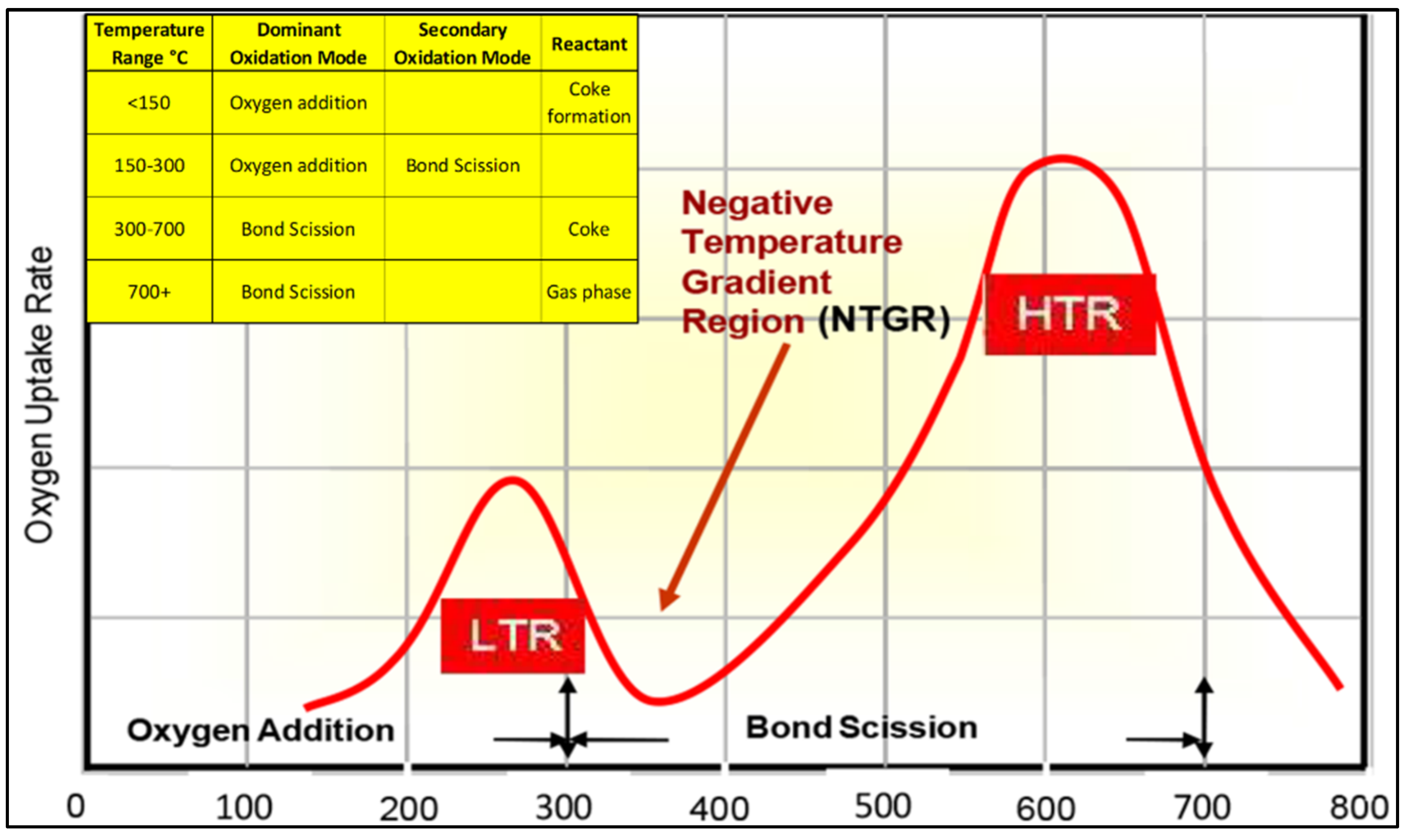
According to Moore [57], the temperature range for LTO reactions depends on the oil composition. As observed in Figure 4, for heavy oils, LTO reactions observe a rapid oxygen uptake period, but after this, it has been evidenced that there is a decline in the oxygen consumption rate at a temperature range of 250 to 300 °C. Dechaux et al. [62] refer to this zone as the “negative temperature gradient region” (NTGR). The pyrolysis reactions take place within this region [63].

4.2. Medium-Temperature Oxidation Reactions

Based on the previous figure, the negative temperature gradient region (NTGR) represents a specific temperature range where the rate of chemical reactions declines. Consequently, the oxygen uptake rate reaches its minimum value. It is within this region that significant reactions such as pyrolysis, thermal cracking, or intermediate-temperature oxidation take place. These reactions yield abundant fuel or coke, characterized as a low volatile heavy hydrocarbon insoluble in toluene. The resulting coke is deposited within the mineral matrix, contributing to the maintenance of the combustion front [4,65]. It has also been noticed that when operations cannot overcome the NTGR, the oxidation kinetics cannot switch to the high-temperature region, and therefore, much of the oil is left behind as residue [66]. For heavy oils, this NTGR occurs in the 250 to 350 °C range [63,65]. According to Gutierrez et al. [67], the general reaction formula for this thermal cracking is
Hydrocarbon ( liquid ) Hydrocarbon ( liquid   and / or   solid ) + Hydrocarbon   vapor .
The reactions involved in this region are considered endothermic and homogeneous, i.e., they occur in a single phase, in this case, gas–gas. According to Abu-Khamsin et al. [68], thermal cracking reactions undergo three different overlapping stages: distillation, visbreaking (mild cracking), and coking (severe cracking). During distillation, the oil loses most of its light to medium fractions. Visbreaking and coking are considered pyrolysis reactions, where most thermal cracking occurs, and coke is formed. According to Abu-Khamsin et al. [68], the reaction kinetics of pyrolysis takes place in chain reactions as follows:
C rude oil heat Visbroken oil + G as ,
Visbroken   oil heat Coke +   G as .
More recent studies have shown that this NTGR does have some traces of trapped oxygen that react with some of the hydrocarbons in oxygen-induced cracking reactions (oxidative cracking reactions). Remarkably, these reactions play a pivotal role in enhancing the hydrocarbon composition, resulting in the generation of lighter hydrocarbons as thermal cracking reactions increase. Furthermore, these reactions are also thought to be present during 2D and 3D conical combustion experiments [67].
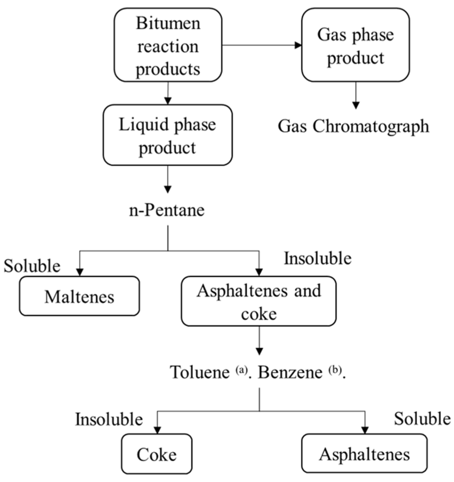
Many authors (e.g., Belgrave [69]) suggest that the studies performed by Hayashitani et al. [70] were of great importance in the kinetic characterization and determination of pseudo components of thermally cracked Athabasca Bitumen. Under an inert condition and temperatures of 360 °C, 397 °C, and 422 °C, they cracked the bitumen and the liquid products were separated into maltenes and asphaltenes-coke residue using n-pentane as a solvent. Asphaltenes were further recovered using benzene as a solvent. They also sub-fractioned maltenes into light, middle, and heavy oils by distillation.
Adegbesan [60] and Belgrave [69] described a pseudo-component LTO reaction scheme for Athabasca bitumen using a semi-flow batch reactor in the 60 °C to 150 °C temperature range and at oxygen partial pressures of 50 kPa to 2233 kPa. Such kinetic characterization led to the duplication of the findings of Hayashitani et al. [70] as far as the separation of the maltenes and asphaltenes-coke fractions in n-pentane. According to Hayashitani et al. [70], coke was characterized as the toluene-insoluble bitumen fraction. Solvent extraction and chromatographic techniques were used in combination to separate the maltenes into saturates, aromatics, oils, and resins (see Figure 5).

4.3. High-Temperature Oxidation Reactions (HTO)

According to Belgrave et al. [52], these reactions mainly occur at the ISC front. In this region, the oxidation reactions burn the deposited coke in the presence of oxygen. These reactions are known as fast bond-scission reactions that produce carbon oxides, carbon monoxide, water, and energy [71]. According to the literature, the HTO reactions occur between the oxygen and the coke laid down at temperatures between 380 and 800 °C [41]. It has been demonstrated that the effective mobilization of the oil is only achieved when temperatures reach so high that the oxidation kinetics permit the occurrence of bond-scission reactions.
As stated earlier, oxygen addition reactions are not desired when trying to mobilize heavy hydrocarbons as they promote the formation of stable emulsions with water. On the other hand, bond-scission reactions are extremely effective at mobilizing oil and are the desired state when implementing air injection and heavy oil combustion [2]. Therefore, it is key for a field project to keep the combustion in the HTO region, also known as the bond scission mode, using a continuous supply of oxygen.
The reaction scheme for HTO, according to Storey et al. [24], is as follows:
H T O ( > 350 ° C ) : c o k e + o x y g e n s h o r t c h a i n H C s + C O + C O 2 .

5. Experiments

Laboratory tests can accurately determine critical factors needed to implement an in situ combustion project in a reservoir system. According to Gutierrez et al. [2], oxidation and combustion tests are performed mainly for three reasons:
1.
To gain a deeper understanding of the oxidation patterns and heat release characteristics of both the oil and the oil/rock systems.
2.
To determine the kinetic parameters associated with the relevant chemical reactions.
3.
To gain an insight into the anticipated recovery performance of the combustion process when implemented in a specific reservoir.
However, there is still no unique test that can cover all these aspects and provide a thorough understanding of the overall performance of ISC. The laboratory tests are classified into quantitative, qualitative, and combustion performance tests and summarized in Table 4.

5.1. Qualitative Tests

According to Gutierrez et al. [2], these are fingerprinting or screening tests capable of estimating the main kinetic parameters involved in the oxidation reactions, including the activation energy, reaction order, and frequency factor. Qualitative tests observe physical changes during combustion, helping to identify key associated parameters. However, they are not recommended when trying to replicate the flow conditions in the reservoir as they do not provide insight into the recovery performance.
In the literature [4], these tests are found to be the Thermogravimetric Analyzer (TGA), Differential Thermal Analyzer (DTA), High-Pressure TGA, Differential Scanning Calorimeter (DSC), Pressurized Differential Scanning Calorimeter (PDSC), and Accelerated Rate Calorimeter (ARC). Overall, it can be said that these techniques are qualitative, rapid tests that calculate the kinetic parameters assuming one single kinetic reaction model, which is not necessarily what happens in the reservoir. For more details about each test, the reader is encouraged to read the extensive insight provided in Chapter 3—Kinetics and Combustion Tube Studies by Sarathi [4].

5.2. Quantitative Tests—Ramped-Temperature Oxidation Test (RTO)

According to Moore et al. [71], a good oil for in situ combustion recovery must be screened in terms of two different parameters: the kinetics of the ignition and how the transition from the low- to high-temperature oxidation regimes occurs. Therefore, the RTO involves heating oil-saturated cores in a plug flow reactor under a continuous stream of air or oxygen-enriched gas. This has proven to be extremely useful in defining the different reaction kinetics and oxidation regimes (i.e., oxygen addition reactions vs. bond-scission reactions) and understanding their impact on oil recovery [4,41,71].
It is important to note that the RTO is not meant to replicate the procedures and results of a combustion tube test or field operation. This is because 1D combustion tube tests are incapable of predicting the minimum air flux as these apparatuses implement high heat capacities, thus making it extremely difficult for the kinetics to achieve the high-temperature combustion mode [65].
According to Moore et al. [71], the objective of an RTO test is to highlight the importance of the negative temperature gradient region and to understand that the effectiveness of the in situ combustion process depends on the oxidation mode and temperature. It is crucial that numerical simulators also incorporate this negative temperature gradient region to have a valid in situ combustion model [66].

5.3. Combustion Performance Tests (Combustion Tube Tests)

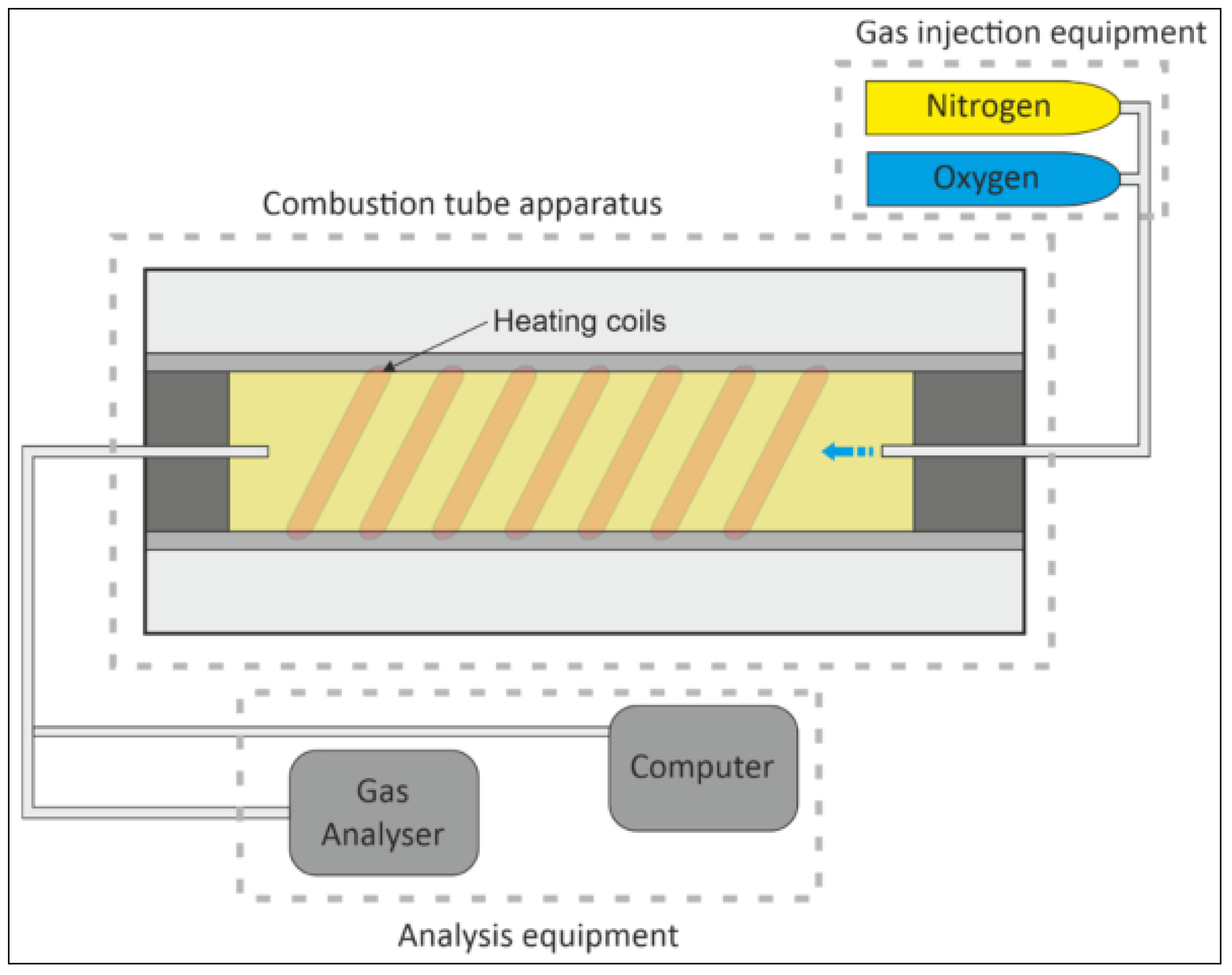
The combustion tube in Figure 6 is a traditional device utilized to maximize oil recovery and make informed decisions by evaluating the in situ combustion performance, air requirements, behavior, and failure criteria in a laboratory setting. These tests usually comprise tubes with a thin stainless-steel wall and are packed with reservoir material like sand and rocks. After the packing has been carried out, the sample is saturated with crude oil, and then the tube is enclosed in a pressure jacket. The reservoir material saturated with oil is then ignited to replicate the behavior of oil in a reservoir during in situ combustion. It is also important to note that the tests must be conducted in an adiabatic condition so no heat transfer is present. Therefore, it is suggested that heaters and a piece of insulation equipment are used. However, there is some discrepancy as some studies suggest that some of the heaters used can cause the unwanted displacement of the combustion front, thus skewing the experiment’s results [72].
Much of the literature has found innovative ways to investigate different aspects of combustion experiments. Some assess the factors influencing the fuel deposition and air requirements of ISC [54,73]. These authors agree that fuel (in the form of coke) availability is governed by the hydrogen-to-carbon ratio (H/C ratio), oil density, and oil saturation (availability of fuel decreased as the H/C ratio and API gravity increased, but it increased for higher oil saturation). On the contrary, there are some authors like Gutierrez et al. [74,75] who differ from the conventional belief that coke is the primary fuel for in situ combustion (ISC). According to their work, laboratory tests and field data have shown that light oils, with limited coke deposition, can still achieve successful ISC projects. Aleksandrov et al. [76] investigated the influence of fracture orientation on the air injection direction in the success of an ISC project. Their study showed that parallel fractures led to poorer ISC performance than perpendicular fractures. Other studies [77] have been conducted focusing on the role of some clay minerals that act as catalytic agents during the reactions of the ISC. The study found that ISC consumed saturates as an ignitor, increased the aromatics fraction, reduced viscosity, and decreased the amount of asphaltenes in produced oil. It also found that the presence of clays aided the combustion process by forming cribriform structures on the asphaltenes’ surface.
Despite all these findings, it has been well studied that the main application of the combustion tube tests is the assessment of the “compatibility” of the crude oil found in the reservoir and how it impacts the coke deposition, air requirements, pressure, temperature, and ultimately, how the combustion front can propagate [40,78,79,80]. When properly designed and conducted, a combustion tube test can yield valuable information about the combustion characteristics of the rock/oil system being tested. Additionally, this data can aid in creating accurate engineering and economic projections of how a field test will perform. Therefore, laboratory combustion tube studies serve as a crucial initial phase in the design of an ISC project.

6. Simulation Coupling

Several numerical simulators have tried to model the reaction kinetics involved in ISC. For instance, Belgrave et al. [52] proposed a comprehensive reaction kinetics model including LTO, thermal cracking, and HTO. This model has been widely used to simulate lab- and field-scale ISC processes [65,81,82,83]. Here, coke was the only fuel for HTO, and bitumen was only composed of maltenes and asphaltenes. Other authors, like Jia et al. [84], proposed a four-reaction kinetic model, which divided the maltenes into a slow reactive and more reactive fraction. However, their study did not provide any detailed information on these fractions. Additionally, there exists a study conducted by Ado et al. [85] that delves into a comparison of the predictive capabilities of different kinetic schemes employed to replicate the THAI process.
Comparable efforts, such as Rojas et al.’s [86] pioneering work, have introduced a concise three-step reaction scheme that adeptly replicates the ignition process, temperature profiles, combustion velocity, and fluid production. This scheme holds promise for its applicability in the scaled-up simulation of in situ combustion scenarios. Yang et al. [87] have contributed by developing a reaction kinetics framework aimed at emulating the post-SAGD in situ combustion process. This comprehensive scheme encompasses Low Temperature Oxidation (LTO), thermal cracking, and High Temperature Oxidation (HTO) reactions. Their study substantially enhances the understanding of fuel nature, with their kinetic model predicting the oxidation and combustion dynamics of Athabasca oil sands. Additionally, Turta et al. [88] conducted an exhaustive analysis that focused on determining ignition delay, as well as the incidence of high-temperature oxidation and LTO reactions. These determinations were meticulously deduced via gas composition analysis.
Some pyrolysis reaction kinetic models based on saturates, aromatics, resins, and asphaltenes (SARA) fractions were developed, including the work of Freitag et al. [89]. Sequera et al. [90] interpreted Jia et al.’s [84] model in a novel manner in terms of SARA fractions. They incorporated a SARA-based LTO (oxygen-addition) model that was based on the simulation and history matching of an RTO experiment. They found that aromatics and resins can oxidize at low temperatures in the presence of an intermediate product (hydroperoxide), thus forming heavier compounds like asphaltenes. This model is the one that has been incorporated into numerical simulators like the thermal simulator STARS™ from CMG. To find a comprehensive list of reaction kinetics schemes used for modeling in situ combustion in the existing literature, the reader is referred to the work carried out by Ahmadi [91] and Storey et al. [24].
Within simulators, chemical reactions are almost exclusively used by combustion processes [92]. These reactions are incorporated as source/sink terms in the mass and energy conservation equations that are solved in numerical simulators. Below is a systematic approach detailing the integration of chemical reactions into a numerical simulator like STARS by CMG. It is crucial to emphasize that all moles and energy associated with each component participating in a reaction are considered. Hence, the stoichiometry of reactions involving a component “i” within reaction “r” must ensure mass conservation. This adherence to mass conservation follows the stipulated principle:
i = 1 n s r , i R M i = i = 1 n s r , i P M i ,
where s r , i R and s r , i P are the reactions stoichiometric coefficients of the reactant and product, respectively, and M i is the molecular mass.
Considering this, in order to build the kinetic model, most simulators often assume multiple LTO reactions, at least one thermal cracking reaction, and two or more HTO reactions. These reactions are modeled using the Arrhenius equation [2,24,93,94,95]. With this equation, the objective is to determine the speed of reaction or reaction rate of either the oxygen uptake or the hydrocarbon (fuel) consumption as follows:
Reaction Rate   ( r k ) = A e E a RT C f u e l a P i b ,
where A is the frequency factor, Ea is the activation energy, C f u e l a is the fuel concentration, P i b is the partial pressure of component i, typically oxygen, and a and b are the reaction orders with respect to the fuel concentration and partial pressure of oxygen, respectively.
According to CMG [92], the general, heterogeneous mass transfer of the reaction taking place is commonly represented by
i = 1 n s r , i R i = 1 n s r , i P + H r k ,
where H r k is the enthalpy of the reaction r.
As such, if one decides to conduct a rearrangement, incorporating the reaction rate r k yields
Q i r e a c = k = 1 n ( s r , i P s r , i R )   ×   r k ,
Q h , r e a c = k = 1 n H r k × r k
where Q i r e a c and Q h , r e a c are the chemical reactions terms.
These are the chemical reaction terms that commercial reservoir simulators incorporate into the mass balance and energy balance conservation equations as source/sink terms. As detailed in the work carried out by Nissen et al. [95] and Zhu et al. [96], these governing equations follow:
Mass balance equation:
C i t + · q i = Q i w e l l + Q i r e a c ,
Energy conservation equation:
U i t + · q h , a d v + q h , c o n d = Q h , w e l l + Q h , r e a c ,
where C i is the concentration of component i, U i is the internal energy, q i is the molar flux for component i q h , a d v and q h , c o n d are advection and conduction terms, respectively, and Q i w e l l and Q h , w e l l are well sink/source terms. Incorporating Equation (6) into Equations (8) and (9) yields the coupled terms:
Q i r e a c = k = 1 n ( s r , i P s r , i R )   ×   A e E a RT C f u e l a P i b ,
Q h , r e a c = k = 1 n H r k   ×   A e E a RT C f u e l a P i b
Now, incorporating Equations (12) and (13) into the governing Equations (10) and (11) gives:
C i t + · q i = Q i w e l l + k = 1 n ( s r , i P s r , i R )   ×   A e E a RT C f u e l a P i b ,
U i t + · q h , a d v + q h , c o n d = Q h , w e l l + k = 1 n H r k   ×   A e E a RT C f u e l a P i b .
Current enhanced oil recovery (EOR) modeling techniques focus on optimizing recovery factors. Given the economic inviability and technical complexity of field tests, initial experimental and numerical modeling becomes important. Thus, to attain a thorough grasp and proficient application of in situ combustion (ISC) methods, it becomes crucial to conduct preliminary experimental work (i.e., via ramped temperature oxidation or combustion tube laboratory experiments) to establish a suitable kinetic reaction model and the corresponding kinetics parameters. Subsequently, utilizing a simulator, one can predict ISC technique performance within a modeled 3D cell through history matching the aforementioned kinetic model and parameters. After these kinetic parameters have been history-matched, they must be correctly up-scaled for a field-scale simulation [97,98].
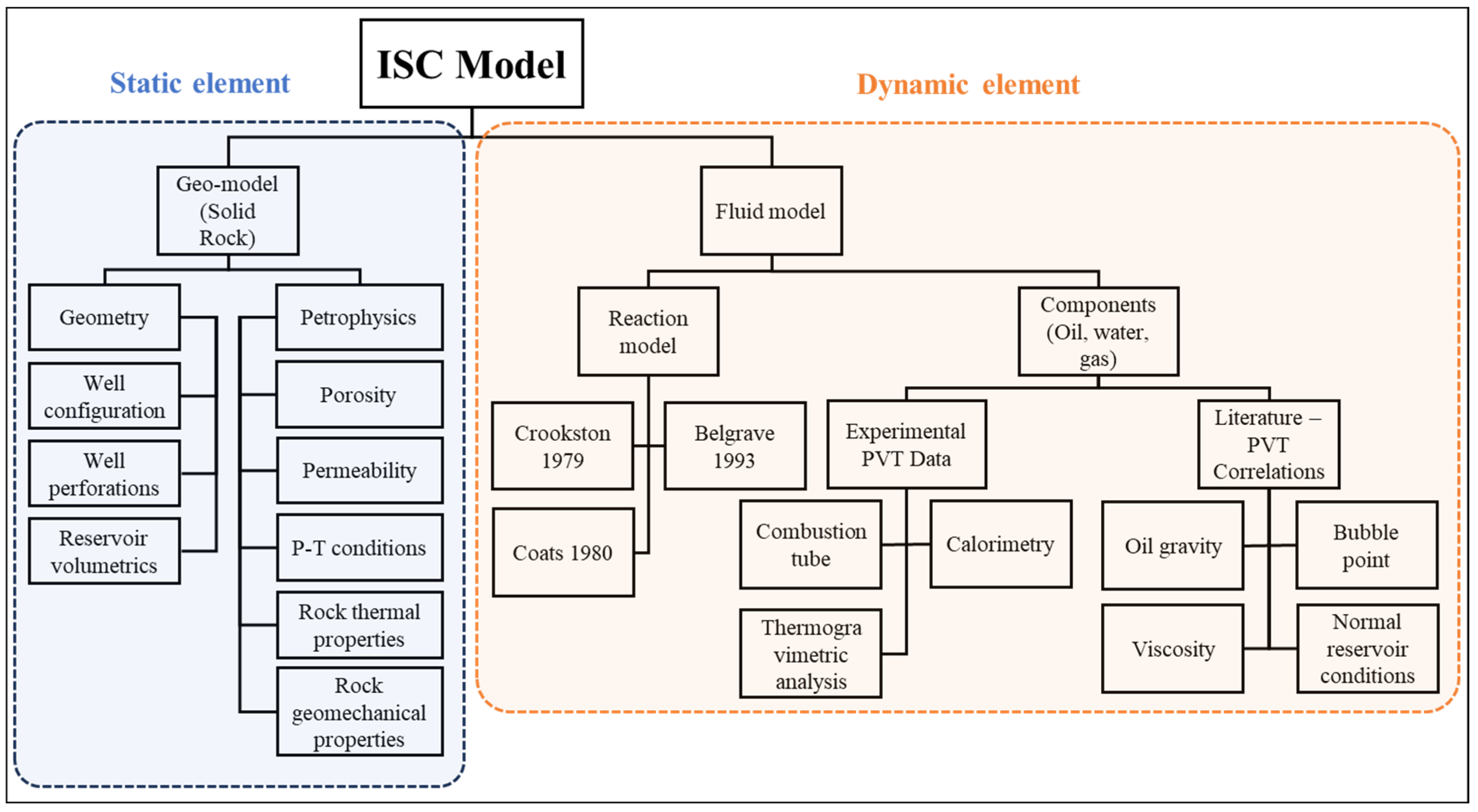
As explained by Storey et al. [24], when dealing with reservoir simulation and model construction, there are two important elements to consider: the geological (static) model, which represents the solid volume of the reservoir, and the fluid (dynamic) model, which represents the fluid volume (oil, water, and gas) that is found inside the reservoir. After the static model has been created, the dynamic behavior has to be incorporated by means of production and injection wells. ISC simulations must include this step to properly capture the dynamics of the process. In the same regard, the modeling process entails meticulous numerical data input into a simulator to ensure accurate results. Static properties such as porosity, permeability, petrophysical, geological, and PVT properties can be derived from an analogous reservoir or obtained through laboratory experiments. Conversely, obtaining thermodynamic and kinetic properties requires conducting combustion tests. This meticulous data collection and modeling process aims to develop an accurate ISC model, thereby maximizing its efficacy when applied in the field.
ISC simulations typically demand high resolution to capture all relevant attributes, consequently slowing down the computational process. As previously mentioned, given the considerable expense and complexity of field tests, modeling ISC is a prerequisite. Figure 7 provides a comprehensive overview of the static and dynamic properties involved in the process.

Challenges in ISC Simulations

One of the main challenges when dealing with numerical simulations of the ISC process is the fact that the data obtained from combustion tube history matching cannot be used directly for field simulations [99]. This limitation stems from the narrow nature of the combustion front. To accurately capture the kinetics involved at play, it is necessary to model this region with small grid blocks in order to capture the kinetics involved. Therefore, if larger grid block sizes were employed, there would be major numerical errors observed like the excessive amounts of fuel consumed, high temperatures in reaction zones, and slower movement of the reaction zone. As kinetic data estimated from the combustion tube history match are time and temperature dependent, they will not produce similar results in large grid blocks. In order to avoid this issue, different techniques have been employed like dynamic gridding, although it does not entirely solve the grid-size problem in the field-scale simulation, as explained by Zhu et al. [99]. Nevertheless, more novel approaches, incorporating the use of the Damköhler number, are successfully used to solve the effects of the grid-size effect in field-scale simulations [95].
According to Gutierrez et al. [2], some challenges must be addressed when modeling a dry combustion test. For instance, there is a tendency to operate a combustion tube test under ideal conditions, where the oxygen uptake is controlled by the rate of consumption of oxygen in the combustion front. Therefore, the process is 100% efficient. Given such conditions, predicting whether the process will shift to the wrong oxidation mode is impossible. Another problem is that combustion tests do not provide kinetic information. Hence, it is important to obtain this data from RTO experiments.
Neglecting the importance of minimum air flux: Trusting field-scale simulation models that have very low or even zero activation energy would yield misleading performance forecasts at lower air injection rates than those specified by the necessary minimum air flux to sustain combustion.
Numerical simulators must incorporate reaction schemes capable of predicting the negative temperature gradient region (NTGR) to become valid over a broad range of operating conditions. Therefore, being able to match combustion tube tests [66]. For heavy oils and bitumen, the NTGR is a zone with low energy generation, so it acts as a barrier to the temperatures shifting from the LTO mode to the HTO mode. Conversely, if the energy generation in the HTO is below the energy level needed to offset the heat losses, then the NGTR can promote the transition from HTO to LTO mode.
Simulation coupling of in situ combustion involves combining numerical models of various aspects of the process, such as fluid flow, heat transfer, and chemical reactions, to create a comprehensive model of the in situ combustion process. Important comments and insight are found in the work carried out by Gutierrez et al. [2]. Furthermore, Ado et al.’s [100] research provides an instance of a model that forecasts operational factors, such as fuel accessibility and generated oxygen concentration, throughout in situ combustion procedures. This contribution enhances comprehension of the THAI technology. Another study, such as the research carried out by Zhu et al. [101], focuses on evaluating the stability of the combustion front. They utilize a numerical simulation tool that serves as an engineering resource to facilitate the planning and execution of real-world ISC projects.

7. Pilots and Field Experience

Since the 1920s, ISC has been employed extensively, with over 230 projects successfully executed in the United States, including notable ones like Bellevue, Midway Sunset, and Belridge. Additionally, several testing initiatives took place in Canada, including the Battrum, Eyehill, Tangleflags, Lindberg, and Countess projects. Subsequently, in the 1980s, numerous field projects were initiated in Europe, particularly in Romania, Hungary, and the former Soviet Union (now Russia and Kazakhstan), with the Suplacu de Barcau project being a prominent example.

7.1. Suplacu de Barcau, Romania

This is the world’s largest and most successful project of in situ combustion, continuously producing since the mid-1960s [13,42,53,102]. The project employs dry forward in situ combustion from top to bottom at low pressures (200 psi). In this scenario, the oil viscosity reaches a substantial level of approximately 2000 cp at a reservoir temperature of 64.4 °F (18 °C). To enhance production, a peripheral direct line drive mechanism is implemented using vertical wells.
The field exhibits an anticline fold with an axial fault named Suplacu de Barcau. This fault serves as a boundary that confines the field to the South and East. The structure has a thickness ranging from 14 to 80 ft (4–24 m) and is situated at a depth of 115–660 ft (35–220 m) [13,42]. Initially, in 1960, the reservoir operated under a solution gas drive mechanism, leading to an oil recovery rate of approximately 9%. The field experienced a modest peak production of 36 barrels per day during its early stages, gradually declining to 6 barrels per day per well in 1962 [13,42].
As a result, in order to confirm the theoretical models, a decision was made to test in situ combustion (ISC) and steam drive (SD) methods between 1963 and 1970. The successful performance in 1970 led to the decision to choose ISC for commercial exploitation. Also, given the high viscosity of 2000 cp, cyclic steam stimulation (CSS) was selected as a necessary preheating procedure at this stage, and the decision to switch from pattern to line-drive exploitation mode was also made by Panait-Patica et al. [13].
Two pilot projects were conducted, consisting of ISC patterns that spanned 4–5 years. One pattern focused on sweeping from the upper section of the anticline, while the other was implemented closer to the water–oil contact near the bottom. However, the data showed that the pattern at the bottom was not as efficient and controlled compared to the top pattern. Therefore, the decision was made to start sweeping the reservoir from the top in a downward manner to achieve better results [13].
The first linear in situ combustion (ISC) front was initiated in 1979 and gradually expanded, reaching zones in the western part of the reservoir. The initial well performance indicated a remarkable oil recovery rate of 55%. To sustain ISC propagation and maintain performance, another linear ISC front was introduced in the eastern part of the reservoir by 1983. However, despite efforts, the second ISC front was ultimately abandoned in 1996. Subsequently, starting in 1998, injection rates were reduced, leading to a progressive decline in oil production [103].
Between 1985 and 1991, oil production peaked, primarily attributed to the effective utilization of the maximum air injection rate. Nevertheless, a significant challenge throughout the implementation of ISC has been the leakage of some combustion gases to the surface, as highlighted by Turta et al. [42]. By 2007, it was estimated that an additional 20 years would be required to propagate the combustion front throughout the entire reservoir.
As of 2013, the field was producing approximately 8000 to 10,000 barrels per day, as reported by Welch et al. [104]. Also, these authors claim that the sustained success of the project can be attributed to factors such as the reservoir geometry and the provision of adequate air injection to support the expansion of the combustion front in a linear manner.

7.2. Santhal and Balol Projects

The Santhal and Balol fields are situated in the Mehsana heavy oil belt, located in the northwestern part of Gujarat, India. These fields were discovered in the early 1970s and have been under exploitation since 1974 in Santhal and 1985 in Balol by ONGC. The reservoir is found at an approximate depth of 1000 m or 3000 ft. It exhibits a strong lateral water drive, which poses challenges due to its unfavorable mobility ratio [42]. Moreover, the oil extracted from these fields through the wet ISC method had a viscosity of up to 200 cp for Santhal and 1000 cp for Balol. The average porosity, permeability, and water saturation for both fields are approximately 28%, 5 darcies, and 30%, respectively [64,105].
Initially, sucker rod pumps and screw pumps were installed for production purposes. However, in Balol, the water production increased while the oil recovery remained low at only 13% due to the unfavorable mobility ratio between oil and water. Consequently, the implementation of a thermal-enhanced oil recovery method became imperative. Initially, both steam injection and in situ combustion were considered potential approaches. However, steam flooding was deemed unfeasible due to the limited depth of 1000 m, an average pay thickness of 5 m, and the presence of a robust water drive [56]. As a result, an initial pilot-scale ISC test was conducted in 1990 to evaluate its effectiveness, which yielded positive results indicating the significance of gravity in the movement of air and gases toward the up-dip portion of the reservoir [106].
Based on these findings, a specific oil layer within the field was developed using ISC with a crestal line drive in 1997. The expansion of this approach commenced from the south and gradually extended to cover the entire field in two phases. To confirm the continuity of the reservoir, N2 gas was employed as a tracer [106].
Implementing the ISC technique in Balol yielded significant improvements in oil production and water cut reduction. From 1997 to 2004, the overall oil production increased from 350 m3/day to 700 m3/day, while the water cut decreased from 80% to 55% [105]. The recovery of the Balol reservoir varied across different regions, with approximately 55% recovery in the southern part and 12% in the northern part. The reduced mobility of viscous oil, low vertical sweep, early flue gas breakthrough in the producers, and front stalling were identified as factors contributing to the poor efficiency in the northern part [64].
To address this challenge, efforts were made to modify the displacement methodology by drilling more up-dip vertical injection wells and horizontal production wells from the flanks towards the injectors. This approach aimed to recover heavy oil over shorter distances, improving oil mobility. The optimization strategy offered significant advantages in overcoming oil mobility issues. In 2004, during a peak in air injection, the water cut decreased considerably to 58%. However, when air injection was halted for a period of three months, the water drive mechanisms regained prominence by activating the aquifer. This observation suggests that the injected air has the necessary strength to halt aquifer encroachment, provided there is a proper balance between injected and produced fluids.
The Balol and Santhal projects provided compelling evidence of the benefits of implementing ISC processes with peripheral line drives for reservoirs characterized by a strong lateral water drive. These projects effectively controlled edge water and substantially reduced water cuts in production wells. Additionally, the utilization of wet ISC processes allowed for greater distances between wells, reaching up to 300 m (980 feet), compared to the typical range of 50–100 m (152–305 feet) observed in Suplacu de Barcau and BSOC Bellevue [64]. Although the ultimate oil recovery may have been slightly lower, the wet ISC processes demonstrated the potential for improved well spacing and overall operational efficiency.
By 2013, the ongoing wet and dry combustion operations in Santhal and Balol led to approximately 15,000 barrels per day, further highlighting the success and impact of these ISC processes [104].

7.3. Bellevue Project

This ISC project utilizes dry in situ combustion at low pressure (less than 0.42 MPa or 60 psi) in a shallow reservoir with a low permeability of 700 mD. The oil viscosity in the reservoir is 676 cp, and the project employs a pattern system [42]. The reservoir is divided into three distinct zones, with the upper zone consisting of sand varying in thickness from 15.3 to 21.4 m, the middle zone ranging from 3.1 to 6.2 m thick, and the lower zone varying from 9.3 to 15.3 m thick. Notably, only the upper and lower zones are productive.
This ISC project is situated northwest of Louisiana and stands as the largest ISC project in the United States. The reservoir, which exhibits a dome structure, was discovered in the 1920s, and production rates reached up to 1115 m3/day in 1923. In 1963, Getty Oil conducted an ISC test using an inverted 9-spot pattern. Later in the 1970s, Cities Service Oil and Bayou State Oil Corporation (BSOC) initiated an ISC experiment, which continued until the late 1970s. By 1982, 223 wells had been drilled, resulting in a production of approximately 2750 bbl/day and an air–oil ratio of 3500 sm3/m3. However, CSO and Getty discontinued their projects in the mid-1980s, leaving BSOC as the sole operator in the field [42].
The ISC project, initiated by BSOC in 1970, initially operated in three inverted 7-spot pattern settings, achieving an oil recovery rate of 10%. In 1972, seven additional patterns were introduced to operate in the lower sand. Subsequently, in 1983, three more patterns were added to operate in the upper sand, transforming the operation into a simultaneous ISC process in both sands. By 2004, 15 well patterns were operating concurrently in the upper and lower zones. The project involved injecting 45,000 sm3/day of air, resulting in a production rate of 50 m3/day [42].
The ignition process in this project employs electrical heaters and has been enhanced by leveraging the reservoir’s high heterogeneity. The objective is to inject a significant amount of heat during ignition and gradually increase the air rate at a controlled and slower pace once the front is established. This approach has proven highly effective, significantly improving performance, increasing oxygen utilization, and enhancing oil production.

7.4. Whitesands Project Pilot—First THAI Pilot near Conklin, AB, Canada

Early pilots of conventional in situ combustion (ISC) in Canada typically involved vertical injector and production wells. The ignition of oil was performed either through downhole burners or steam injection. However, as noted by Welch et al. [104], these pilots encountered several recovery challenges, including high sand production, erosion and corrosion of production well tubing strings, high lifting costs, and the formation of stubborn emulsions.
In response to these challenges, the Canadian operator—Petrobank—recognized the potential of the Toe-to-Heel Air Injection (THAI) technology for extracting heavy hydrocarbons in Alberta’s Athabasca Oil Sands region. Consequently, in 2006, Petrobank and its subsidiary Whitesands Insitu Ltd. launched their first-ever pilot using the THAI approach near Conklin, Alberta. The pilot comprised three well pairs, three air injector wells, and three production wells operating in a direct line drive configuration [104].
According to Turta et al. [107], the pilot was operated for 5 years, but it was observed that significantly less oxygen was injected than originally planned. Preheating through steam injection was carried out for 3–4 months, followed by ignition within 1–2 months. As the operation stabilized, the oil production per well peaked at 10–20 m3/day. The project produced 180,000 barrels with an air–oil ratio of 5000–6000 sm3/m3. However, the pilot was eventually suspended due to unfavorable confinement in the pilot area, migration of combustion gases into the McMurray “A” formation, and communication with the bottom water zone from the start of steam injection. The failure of the project was further compounded by factors such as sand influx and poor casing performance in the horizontal wells. Moreover, the lack of experience in handling projects of this nature exacerbated the operational challenges.
Another contributing factor to the project’s failure was using a direct line drive (DLD). It was observed that the combustion front advanced less than 40 m, less than half of the estimated distance from the toe to heel along the horizontal well. At the pilot’s conclusion, only 7% of the oil was recovered, highlighting that the DLD configuration was unsuitable for achieving optimal sweep efficiency [107].

7.5. Kerrobert

Whitesands Insitu Ltd. holds the rights and permits to operate in the Kerrobert lease, a 10 km2 area situated 15 km southwest of the town of Kerrobert in Saskatchewan. The lease contains a reservoir at a depth of 740 m, housing heavy oil in the Waseca Formation along with a significant bottom water zone. Initially, conventional methods were employed to exploit these resources using two horizontal wells. Subsequently, in July 2009, approval was obtained for a Toe-to-Heel Air Injection (THAI) pilot consisting of two well pairs. Drilling and completion were successfully carried out in the same year, followed by the initiation of air injection in October 2009 [104].
By the end of 2010, oil production reached 150 barrels per day. The air-to-oil ratio between the two initial wells ranged from 1000 to 2000 sm3/m3 in 2010. According to [104], the native oil was estimated to have a viscosity of 53,000 cp and an API gravity of 10°. However, the recovered oil was sold with a viscosity of 344 cp and an average density of 15.7° API, indicating that the THAI process effectively upgraded the oil.
Regarding reaction kinetics, gas analyses confirmed the occurrence of high-temperature oxidation reactions essential for sustaining a favorable in situ combustion mechanism. The produced gases exhibited a composition with only 0.5% oxygen, indicating complete consumption of oxygen.
During the third quarter of 2010, the performance evaluation of the Kerrobert pilot demonstrated excellent results in implementing the THAI technique. Consequently, the operator proceeded with the expansion of the pilot into a semi-commercial-scale project by drilling ten additional well pairs. By 2011, the construction of the THAI semi-commercial-scale project was completed. The preheating phase involved steam injection for 1–2 months, followed by ignition. However, the ignition process proved inefficient, resulting in a delay of 6 months. This delay led to low-temperature oxidations, which unfavorably mobilized the oil. Once the ignition phase passed, the in situ combustion front became clearer, as evidenced by gas composition. Regarding production, the well rates ranged from 7 to 14 m3/day with a water cut between 30 and 50%. The total oil produced as of February 2015 reached around 50,000 m3. The pilot confirmed an upgrade of about 7° API, while the expansion project achieved approximately 5° API. Additionally, the air-to-oil ratio was approximately 1500 sm3/m3 for the pilot and around 2400 for the semi-commercial project [104]. For a detailed analysis of the operation at Kerrobert, the reader is directed to the work conducted by Wei et al. [108].

7.6. China

China’s heavy oil production faces significant challenges, largely stemming from the late-stage use of conventional steam flooding methods. These methods are plagued by inefficiencies due to substantial heat losses during implementation. As a result, it is imperative to explore more effective alternatives, such as in situ combustion, which has undergone testing in oil fields including Shengli, Liaohe, Jilin, and Xinjiang [109,110]. A notable case presented by Zhu et al. [99] involves the implementation of this technology in the D block (Du-66 reservoir) within Liaohe Oilfield, a project initiated back in 1986 [110].
The Du-66 reservoir, characterized by its monocline, exhibits a dipping angle of 5–10 degrees. The reservoir area spans 8.4 km2 with an original oil in place of 5000 × 104 tons (357 MMbbl). Depths range from 800 to 1300 m, with a porosity of 0.25 and average permeability of 800 mD within the poorly consolidated sandstone reservoir. Crude density is measured at 0.93 g/cm3, while oil viscosity stands at 300–2000 cp at 50 °C [110,111].
Initially, the block underwent cyclic steam stimulation; however, results fell short of expectations. The recovery factor notably lagged behind the projected 27%, and the pressure plummeted from 11 MPa to 1.5 MPa. Consequently, in 2006, in situ combustion emerged as a post-CSS strategy to enhance recovery rates and economic viability. The ensuing pilot comprised an inverted nine-spot well pattern, involving over 90 ISC well patterns designed for air injection, while the remaining wells still adhered to CSS [110].
The transformation from steam flooding to in situ combustion, as detailed by Yao et al. [109], yielded a substantial increase in single-well average daily production, rising from 0.5 t/d (3.66 bbl/day) to 3.8 t/d (27.85 bbl/day). The reservoir’s total daily production surged to 619 t/d (4424 bbl/day) by 2017 and an upgrading of 2–6° API [112].
Moreover, the application of Toe-to-Heel Air Injection (THAI) technology has seen three distinct pilots. There was a fire flooding pilot conducted in 2008 in the District Gao2-3 of Liaohe Oilfield. In it, a novel reusable igniter mechanism was used, which features a three-wire nickel chrome alloy coated in magnesia, to produce enough heat for ignition [111,113].
The inaugural Shunguang Pilot, as outlined by Wang et al. [111], underscores the prominence of Liaohe Oilfield as China’s largest hub for heavy oil production. Over time, ISC has been effectively deployed across a spectrum of reservoir types, including thin bed heavy oil, deep heavy oil, and bottom water reservoirs, showcasing its adaptability and impact [109].

8. Criteria for Selecting ISC

Screening criteria for field projects should be based on specific oil, water, rock, reservoir, and previous performance properties. According to Sarathi [4], it is challenging to establish a definitive guideline for the application of ISC technology due to the diverse scenarios and rock characteristics encountered in previous applications. However, an effective screening guideline should consider rock type, oil type, and geological requirements. To provide useful insights, this paper compiles and summarizes commonly found screening guidelines from the literature pertaining to the commercial exploitation of heavy oil using ISC. Table 5 presents a summary of these informational screening guidelines.
It is important to mention that in cases where the initial oil saturation exceeds 50%, potential challenges arise due to the reduced availability of pore space for air injection and combustion reactions. This can lead to limited air penetration and hinder efficient combustion propagation. To optimize ISC performance, enhancing reservoir rock permeability, employing proper well placement, and adjusting injection strategies are crucial. These measures help ensure better air distribution, facilitate combustion front advancement, and ultimately improve recovery efficiency in reservoirs with high initial oil saturation [114].
In addition to this, Chu [9] has postulated that the fuel content typically falls within the range of 0.8 to 2.8 lb/cu ft, with an average value of 1.45 lb/cu ft. Moreover, they suggest that the air-fuel mass ratio for both experimental and field-scale operations usually lies between 8 and 13, with an average of 9.65. Furthermore, the same author has proposed an average air–oil ratio of 12,400 scf/bbl for field-scale operations. In contrast, Turta et al. [42] have presented differing findings, stating that this parameter oscillates within a broader range of 1000 to 4500 sm3/m3 (equivalent to 6000–25,000 scf/bbl).

9. Future Work

Further research is required to fully comprehend the environmental consequences associated with in situ combustion and to assess the economic viability of these processes. In addition, comprehensive studies are needed to evaluate the impact of ignition operations.
Since its initial field application in 2006, THAI technology has demonstrated its technical feasibility. The investigation and implementation of the direct line drive (DLD) configuration have already been conducted. However, a more extensive understanding of the staggered line drive (SLD) implications in THAI technology is necessary. This can be achieved through dedicated 3D simulations, as such simulations have indicated the superiority of the SLD scheme in terms of fire front stability. Furthermore, systematic field testing of the SLD configuration should be conducted to validate its effectiveness [115].
Research on in situ combustion extensively investigates experiments and laboratory models. The kinetics behavior of this technology, along with simulations of lab scale models, has been widely studied. The authors believe that more emphasis should be placed on accurately upscaling from lab- to field-scale models [98,99]. This effort is crucial to comprehending the intricate yet captivating nature of this technology.
Similarly, numerical models need to consider various factors including different completion settings, well design, injector and producer wellbore placement, injection of pure oxygen [116], heterogeneities [117] and the presence of bottom water and clays in the rock matrix [118,119,120,121], all of which could significantly influence the technique’s success.
Moreover, it is essential to place greater emphasis on comprehending the potential of ISC to generate hydrogen from bitumen. According to Song et al. [122], the capacity of the oil and gas industry to play a substantial role in the energy transition by enabling extensive and economical hydrogen production from reservoirs is noteworthy. Equally important is the necessity to understand the pre-injection heating cycle (PIHC) to unravel the complexities of ignition prior to the commencement of air injection. Additionally, understanding the application of ISC in depleted conventional oil reservoirs to increase recovery factors and its integration with steam injection are essential aspects to consider [123,124].

10. Conclusions

In conclusion, the in situ combustion technique is a promising method for enhanced oil recovery. The kinetics involved in the process are complex and require careful consideration when designing and implementing the technique. The use of laboratory tests is essential in optimizing the process and predicting its performance in the field. Additionally, it is important to incorporate and history-match the kinetics attributes with numerical simulations to accurately predict the behavior of the process. Upscaling the simulation to field conditions is another challenge that requires further research and detailed analysis.
The success and effectiveness of in situ combustion (ISC) projects vary depending on various factors such as reservoir characteristics, operational parameters, and project design. To ensure precise and appropriate implementation of the ISC technology at the field scale, and to offer valuable insights, this paper presents and condenses screening guidelines for its application.
The case studies highlighted the importance of understanding the specific reservoir conditions and tailoring the ISC approach accordingly. Projects like Balol and Santhal demonstrated that implementing ISC techniques in peripheral line drives can significantly reduce water cuts and control edge water, increasing oil production. On the other hand, projects like the Canadian Whitesands pilot using THAI technology faced challenges such as inefficient ignition and unfavorable combustion front advancement, which affected the overall performance. These experiences underscore the need for thorough reservoir characterization, operational optimization, and continuous monitoring to achieve successful ISC implementation.
Recent studies have highlighted the potential of the THAI and the Catalytic Upgrading Process in situ (CAPRI) combustion techniques as viable alternatives to traditional in situ combustion [125,126,127,128]. These techniques have shown promising results in the laboratory and field. However, further research is needed to optimize their performance in terms of operational design and ignition initiation.
Overall, the development and optimization of the in situ combustion technique and the continued research into novel approaches such as THAI and CAPRI will be critical for the continued production of hydrocarbons from unconventional resources. The successful implementation of these techniques will lead to increased hydrocarbon recovery and more efficient and sustainable production practices.

Author Contributions

J.D.A. (Conceptualization, methodology, validation, investigation, writing—original draft preparation); R.M. (methodology, validation, formal analysis); A.N. (validation, writing—review and editing, funding acquisition, supervision). All authors have read and agreed to the published version of the manuscript.

Funding

This research was funded by The Natural Sciences and Engineering Research Council of Canada (NSERC) through the Discovery Grant RGPIN-2017-06257 and the Canada First Research Excellence fund through the Future Energy Systems (Thermal Well Design and Testing).

Data Availability Statement

Data sharing not applicable.

Conflicts of Interest

The authors declare no conflict of interest.

References

  1. Moore, R.G.; Laureshen, C.J.; Ursenbach, M.G.; Mehta, S.A.; Belgrave, J.D.M. A Canadian Perspective On In Situ Combustion. J. Can. Pet. Technol. 1999, 38, 1–8. [Google Scholar] [CrossRef]
  2. Gutierrez, D.; Skoreyko, F.; Moore, R.G.; Mehta, S.A.; Ursenbach, M.G. The Challenge of Predicting Field Performance of Air Injection Projects Based on Laboratory and Numerical Modelling. J. Can. Pet. Technol. 2009, 48, 23–33. [Google Scholar] [CrossRef]
  3. Brigham, W.; Castanier, L.M. Chapter 16 In-situ Combustion. In Petroleum Engineering Handbook, Volume V: Reservoir Engineering and Petrophysics; Holstein, E.D., Ed.; Society of Petroleum Engineers: Richardson, TX, USA, 2007; Volume V, pp. 1367–1398. [Google Scholar]
  4. Sarathi, P.S. In-Situ Combustion Handbook—Principles and Practices; Office of Scientific and Technical Information (OSTI): Tulsa, OK, USA, 1999. [Google Scholar]
  5. Wolcott, E.R. Method of Increasing the Yield of Oil Wells. U.S. Patent 1,457,479, 5 June 1923. [Google Scholar]
  6. Howard, F.A. Method of Operating Oil Wells. Patent US1473348A, 6 November 1923. [Google Scholar]
  7. Kuhn, C.S.; Koch, R.L. In-Situ Combustion newest method of increasing oil recovery. Oil Gas J. 1953, 92, 113. [Google Scholar]
  8. Grant, B.F.; Szasz, S.E. Development of an Underground Heat Wave for Oil Recovery. J. Pet. Technol. 1954, 6, 23–33. [Google Scholar] [CrossRef]
  9. Chu, C. A Study of Fireflood Field Projects (includes associated paper 6504). J. Pet. Technol. 1977, 29, 111–120. [Google Scholar] [CrossRef]
  10. Cheih, C. State-of-the-Art Review of Fireflood Field Projects (includes associated papers 10901 and 10918). J. Pet. Technol. 1982, 34, 19–36. [Google Scholar] [CrossRef]
  11. Mills, R.V.A. The Paraffin Problems in Oil Wells. In U.S. Bureau of Mines Report of Investigation; Government Printing Office: Washington, DC, USA, 1923. [Google Scholar]
  12. Sheinman, A.B.; Dubroval, K.K.; Charuigin, M.M.; Zaks, S.L.; Zinchenka, K.E. Gasification of Crude Oil in Reservoir Sands. Pet. Eng. 1938, 1, 27–30. [Google Scholar]
  13. Panait-Patica, A.; Serban, D.; Ilie, N. Suplacu de Barcau Field—A Case History of a Successfull In-Situ Combustion Exploitation. In Proceedings of the SPE Europec/EAGE Annual Conference and Exhibition, Vienna, Austria, 12–15 June 2006. [Google Scholar]
  14. Guo, K.; Li, H.; Yu, Z. In-Situ heavy and extra-heavy oil recovery: A review. Fuel 2016, 185, 886–902. [Google Scholar] [CrossRef]
  15. Turta, A. Chapter 18-In Situ Combustion. In Enhanced Oil Recovery Field Case Studies; Sheng, J.J., Ed.; Gulf Professional Publishing: Boston, MI, USA, 2013; pp. 447–541. [Google Scholar]
  16. Castanier, L.M.; Brigham, W.E. Upgrading of crude oil via in situ combustion. J. Pet. Sci. Eng. 2003, 39, 125–136. [Google Scholar] [CrossRef]
  17. Xia, T.X.; Greaves, M.; Turta, A.T.; Ayasse, C. THAI—A ‘short-distance displacement’ in situ combustion process for the recovery and upgrading of heavy oil. Chem. Eng. Res. Des. 2003, 81, 295–304. [Google Scholar] [CrossRef]
  18. Gates, I.D.; Chakrabarty, N.; Moore, R.G.; Mehta, S.A.; Zalewski, E.; Pereira, P. In-situ upgrading of Llancanelo heavy oil using in situ combustion and a downhole catalyst bed. J. Can. Pet. Technol. 2008, 47, 23–31. [Google Scholar] [CrossRef] [PubMed]
  19. Kapadia, P.R.; Kallos, M.S.; Gates, I.D. Potential for hydrogen generation from in situ combustion of Athabasca bitumen. Fuel 2011, 90, 2254–2265. [Google Scholar] [CrossRef]
  20. Kapadia, P.R.; Wang, J.; Kallos, M.S.; Gates, I.D. Practical process design for in situ gasification of bitumen. Appl. Energy 2013, 107, 281–296. [Google Scholar] [CrossRef]
  21. Kapadia, P.R.; Kallos, M.S.; Gates, I.D. A review of pyrolysis, aquathermolysis, and oxidation of Athabasca bitumen. Fuel Process. Technol. 2015, 131, 270–289. [Google Scholar] [CrossRef]
  22. Hart, A.; Wood, J.; Greaves, M. Laboratory investigation of CAPRI catalytic THAI-add-on process for heavy oil production and in situ upgrading. J. Anal. Appl. Pyrolysis 2017, 128, 18–26. [Google Scholar] [CrossRef]
  23. Li, Y.; Wang, Z.; Hu, Z.; Xu, B.; Li, Y.; Pu, W.; Zhao, J. A review of in situ upgrading technology for heavy crude oil. Petroleum 2021, 7, 117–122. [Google Scholar] [CrossRef]
  24. Storey, B.M.; Worden, R.H.; McNamara, D.D. The Geoscience of In-Situ Combustion and High-Pressure Air Injection. Geosciences 2022, 12, 340. [Google Scholar] [CrossRef]
  25. Hajdo, L.E.; Hallam, R.J.; Vorndran, L.D.L. Hydrogen Generation During In-Situ Combustion. In Proceedings of the Society of Petroleum Engineers-SPE California Regional Meeting, CRM 1985, London, UK, 18–20 September 1985; pp. 675–689. [Google Scholar]
  26. Davis, A.P.; Michaelides, E.E. Geothermal power production from abandoned oil wells. Energy 2009, 34, 866–872. [Google Scholar] [CrossRef]
  27. Cinar, M. Creating enhanced geothermal systems in depleted oil reservoirs via in situ combustion. In Proceedings of the Thirty-Eigth Workshop on Geothermal Reservoir Enginerring, Stanford, CA, USA, 11–13 February 2013. [Google Scholar]
  28. Cheng, W.-L.; Li, T.-T.; Nian, Y.-L.; Xie, K. Evaluation of working fluids for geothermal power generation from abandoned oil wells. Appl. Energy 2014, 118, 238–245. [Google Scholar] [CrossRef]
  29. Zhu, Y.; Li, K.; Liu, C.; Mgijimi, M.B. Geothermal power production from abandoned oil reservoirs using in situ combustion technology. Energies 2019, 12, 4476. [Google Scholar] [CrossRef]
  30. Ramey, H.J. In-Situ Combustion. In Proceedings of the 8th World Petroleum Conference, Moscow, Russia, 13 June 1971. [Google Scholar]
  31. Turta, A.T. Conventional ISC. 2022. Available online: https://insitucombustion.ca/#conventional (accessed on 15 May 2023).
  32. Stosur, J.J. Chapter 34-In Situ Combustion Method for Oil Recovery State of the art and Potential. In The Future Supply of Nature-Made Petroleum and Gas; Meyer, R.F., Barnea, J., Grenon, M., Eds.; Elesver: Amsterdam, The Netherlands, 1977; pp. 611–623. [Google Scholar]
  33. Greaves, M.; Saghr, A.M.; Xia, T.X.; Turta, A.T.; Ayasse, C. THAI-New air injection technology for heavy oil recovery and in situ upgrading. J. Can. Pet. Technol. 2001, 40, 38–47. [Google Scholar] [CrossRef]
  34. Greaves, M.; Turta, A.T. Oilfield In-Situ Combustion Process. U.S. Patent US5626191A, 6 May 1997. [Google Scholar]
  35. Ayasse, C.; Bloomer, C.; Lyngberg, E.; Boddy, W.; Donnelly, J.; Greaves, M. First Field Pilot of the THAI Process. In Proceedings of the 6th Canadian International Petroleum Conference (56th Annual Technical Meeting), Calgary, AB, Canada, 7–9 June 2005. [Google Scholar]
  36. Perkins, G. Mathematical modelling of in situ combustion and gasification. Proc. Inst. Mech. Eng. Part A J. Power Energy 2018, 232, 56–73. [Google Scholar] [CrossRef]
  37. Weissman, J.G.; Kessler, R.V.; Sawicki, R.A.; Belgrave, J.D.M.; Laureshen, C.J.; Mehta, S.A.; Moore, R.G.; Ursenbach, M.G. Down-hole catalytic upgrading of heavy crude oil. Energy Fuels 1996, 10, 883–889. [Google Scholar] [CrossRef]
  38. Speight, J.G. Thermal methods of recovery. In Heavy Oil Production Processes; Elsevier Science & Technology: Saint Louis, MO, USA, 2013; pp. 93–130. [Google Scholar]
  39. Yannimaras, D.V.; Tiffin, D.L. Screening of Oils for In-Situ Combustion at Reservoir Conditions by Accelerating-Rate Calorimetry. SPE Reserv. Eng. 1995, 10, 36–39. [Google Scholar] [CrossRef]
  40. Fassihi, M.R.; Yannimaras, D.V.; Kumar, V.K. Estimation of Recovery Factor in Light-Oil Air-Injection Projects. SPE Reserv. Eng. 1997, 12, 173–178. [Google Scholar] [CrossRef]
  41. Moore, R.G.; Laureshen, C.J.; Ursenbach, M.G.; Mehta, S.A.; Belgrave, J.D.M. Combustion/Oxidation Behavior of Athabasca Oil Sands Bitumen. SPE Reserv. Eval. Eng. 1999, 2, 565–571. [Google Scholar] [CrossRef]
  42. Turta, A.T.; Chattopadhyay, S.K.; Bhattacharya, R.N.; Condrachi, A.; Hanson, W. Current status of commercial in situ combustion projects worldwide. J. Can. Pet. Technol. 2007, 46, 8–14. [Google Scholar] [CrossRef]
  43. Montes, A.R.; Gutierrez, D.; Moore, R.G.; Mehta, S.A.; Ursenbach, M.G. Is High-Pressure Air Injection (HPAI) Simply a Flue-Gas Flood? J. Can. Pet. Technol. 2010, 49, 56–63. [Google Scholar] [CrossRef]
  44. Gutiérrez, D.; Moore, R.G.; Ursenbach, M.G.; Mehta, S.A. The ABCs of in-situ-combustion simulations: From laboratory experiments to field scale. In Proceedings of the Canadian Unconventional Resources Conference, Calgary, AB, Canada, 7 March 2012; pp. 256–267. [Google Scholar]
  45. Kisman, K.E.; Lau, E.C. A New Combustion Process Utilizing Horizontal Wells And Gravity Drainage. J. Can. Pet. Technol. 1994, 33, 39–45. [Google Scholar] [CrossRef]
  46. Wei, W. In-Situ Combustion for Heavy Oil: Toe-to-Heel Air Injection; University of Calgary: Calgary, AB, Canada, 2020. [Google Scholar]
  47. Dabbous, M.K.; Fulton, P.F. Low-Temperature-Oxidation Reaction Kinetics and Effects on the In-Situ Combustion Process. Soc. Pet. Eng. J. 1974, 14, 253–262. [Google Scholar] [CrossRef]
  48. Ranjbar, M. Improvement of medium and light oil recovery with thermocatalytic in situ combustion. J. Can. Pet. Technol. 1995, 34, 25–30. [Google Scholar] [CrossRef]
  49. Adagülü, G.D.; Akkutlu, I.Y. Influence of in situ fuel deposition on air injection and combustion processes. J. Can. Pet. Technol. 2007, 46, 54–61. [Google Scholar] [CrossRef]
  50. Gargar, N.K.; Mailybaev, A.A.; Marchesin, D.; Bruining, H. Compositional effects in light/medium oil recovery by air injection: Vaporization vs. combustion. J. Porous Media 2014, 17, 937–952. [Google Scholar] [CrossRef]
  51. Yuan, C.; Sadikov, K.; Varfolomeev, M.; Khaliullin, R.; Pu, W.; Al-Muntaser, A.; Saeed Mehrabi-Kalajahi, S. Low-temperature combustion behavior of crude oils in porous media under air flow condition for in-situ combustion (ISC) process. Fuel 2020, 259, 116293. [Google Scholar] [CrossRef]
  52. Belgrave, J.D.M.; Moore, R.G.; Ursenbach, M.G.; Bennion, D.W. A Comprehensive Approach to In-Situ Combustion Modeling. SPE Adv. Technol. Ser. 1993, 1, 98–107. [Google Scholar] [CrossRef]
  53. Butler, R.M. Thermal Recovery of Oil and Bitumen; Prentice Hall Inc.: Old Tappan, NJ, USA, 1991. [Google Scholar]
  54. Alexander, J.D.; Martin, W.L.; Dew, J.N. Factors Affecting Fuel Availability and Composition During In Situ Combustion. J. Pet. Technol. 1962, 14, 1154–1164. [Google Scholar] [CrossRef]
  55. Moore, R.G.; Laureshen, C.J.; Belgrave, J.D.M.; Ursenbach, M.G.; Mehta, S.A. In-Situ Combustion in Canadian heavy oil reservoirs. Fuel 1995, 74, 1169–1175. [Google Scholar] [CrossRef]
  56. Turta, A.T.; Greaves, M.; Grabowski, J. Comprehensive Assessment of Toe-To-Heel Air Injection (THAI) Process. In Guidelines for Development of Future Generations of In-Situ Combustion Processes; A T EOR Consulting Inc.: Calgary, AB, Canada, 2018. [Google Scholar]
  57. Moore, R.G. New Strategies For In Situ Combustion. J. Can. Pet. Technol. 1993, 32, 11–13. [Google Scholar] [CrossRef]
  58. Moschopedis, S.E.; Speight, J.G. Oxidation of petroleum fractions. Fuel 1973, 52, 83. [Google Scholar] [CrossRef]
  59. Moschopedis, S.E.; Speight, J.G. Oxidation of a bitumen. Fuel 1975, 54, 210–212. [Google Scholar] [CrossRef]
  60. Adegbesan, K.O. Kinetic Study of Low Temperature Oxidation of Athabasca Bitumen; University of Calgary: Calgary, AB, Canada, 1982. [Google Scholar]
  61. Al-Saadoon, F.T. Experimental and Statistical Study of Residual Oil Saturation after Gas, Water, and Steam Drive, and Fuel Availability for the In-Situ Combustion Process; U.S. Department of Energy: Washington, DC, USA, 1970. [Google Scholar]
  62. Dechaux, J.C.; Delfosse, L. The negative temperature coefficient in the C2 to C13 hydrocarbon oxidation. I. Morphological results. Combust. Flame 1979, 34, 161–168. [Google Scholar] [CrossRef]
  63. Alizadeh, A. A Robust Kinetic Model for Computer Modelling of In Situ Combustion Processes in Athabasca Oil Sands. Ph.D. Thesis, University of Calgary, Calgary, AB, Canada, 2020. [Google Scholar]
  64. Sur, S. In-Situ Combustion Myths and Facts. SPE Reserv. Eval. Eng. 2022, 26, 180–189. [Google Scholar] [CrossRef]
  65. Alamatsaz, A. Experimental Investigation of In Situ Combustion for Heavy Oils at Low Air Flux. Ph.D. Thesis, University of Calgary, Calgary, AB, Canada, 2014. [Google Scholar]
  66. Moore, R.G.; Belgrave, J.D.M.; Mehta, S.A.; Ursenbach, M.G.; Laureshen, C.J.; Xi, K. Some Insights Into the Low-Temperature and High-Temperature In-Situ Combustion Kinetics. In Proceedings of the SPE/DOE Enhanced Oil Recovery Symposium, Tulsa, OK, USA, 21–24 April 1992. [Google Scholar]
  67. Gutierrez, D.; Mallory, D.G. New Insights into the Understanding of In-Situ Combustion: Important Considerations When Modeling the Process. SPE Reserv. Eval. Eng. 2022, 26, 122–138. [Google Scholar] [CrossRef]
  68. Abu-Khamsin, S.A.; Brigham, W.E.; Ramey, H.J. Reaction Kinetics of Fuel Formation for In-Situ Combustion. SPE Reserv. Eng. 1988, 3, 1308–1316. [Google Scholar] [CrossRef]
  69. Belgrave, J.D.M. An Experimental and Numerical Investigation of In-Situ Combustion Tube Tests. Ph.D. Thesis, University of Calgary, Calgary, AB, Canada, 1987. [Google Scholar]
  70. Hayashitani, M.; Bennion, D.W.; Donnelly, J.K.; Moore, R.G. Thermal Cracking Models For Athabasca Oil Sands. In Proceedings of the SPE Annual Fall Technical Conference and Exhibition, Houston, TX, USA, 16–18 October 1978. [Google Scholar]
  71. Moore, R.G.; Ursenbach, M.G.; Laureshen, C.J.; Belgrave, J.D.M.; Mehta, S.A. Ramped Temperature Oxidation Analysis of Athabasca Oil Sands Bitumen. J. Can. Pet. Technol. 1999, 38, 13. [Google Scholar] [CrossRef]
  72. Belgrave, J.D.M.; Moore, R.G.; Bennion, D.W. The thermal behavior of vertically-operated near-adiabatic in-situ combustion tubes. J. Pet. Sci. Eng. 1990, 5, 51–65. [Google Scholar] [CrossRef]
  73. Sharma, J.; Dean, J.; Aljaberi, F.; Altememee, N. In-Situ Combustion in Bellevue field in Louisiana – History, current state and future strategies. Fuel 2021, 284, 118992. [Google Scholar] [CrossRef]
  74. Gutierrez, D.; Mallory, D.; Moore, R.G.; Mehta, S.A.; Ursenbach, M.G.; Bernal, A. New Insights into the Understanding of In-Situ Combustion: The Nature of the Fuel and the Role of Operating Pressure. SPE J. 2022, 37, 3579–3597. [Google Scholar] [CrossRef]
  75. Gutiérrez, D.; Mallory, D.; Moore, G.; Mehta, R.; Ursenbach, M.; Bernal, A. New Paradigm in the Understanding of In Situ Combustion: The Nature of the Fuel and the Important Role of Vapor Phase Combustion. In Proceedings of the SPE Improved Oil Recovery Conference, Online, 25–29 April 2022. [Google Scholar]
  76. Aleksandrov, D.; Kudryavtsev, P.; Hascakir, B. Variations in in-situ combustion performance due to fracture orientation. J. Pet. Sci. Eng. 2017, 154, 488–494. [Google Scholar] [CrossRef]
  77. Ismail, N.B.; Hascakir, B. Impact of asphaltenes and clay interaction on in-situ combustion performance. Fuel 2020, 268, 117358. [Google Scholar] [CrossRef]
  78. Tzanco, E.T.; Moore, R.G.; Belgrave, J.D.M.; Ursenbach, M.G. Laboratory Combustion Behaviour of Countess B Light Oil. J. Can. Pet. Technol. 1991, 30, 43–51. [Google Scholar] [CrossRef]
  79. Çınar, M.; Hasçakir, B.; Castanier, L.M.; Kovscek, A.R. Predictability of Crude Oil In-Situ Combustion by the Isoconversional Kinetic Approach. SPE J. 2011, 16, 537–547. [Google Scholar] [CrossRef]
  80. Hascakir, B.; Ross, C.M.; Castanier, L.M.; Kovscek, A.R. Fuel Formation and Conversion During In-Situ Combustion of Crude Oil. SPE J. 2013, 18, 1217–1228. [Google Scholar]
  81. Coates, R.; Lorimer, S.; Ivory, J. Experimental and Numerical Simulations of a Novel Top Down In-Situ Combustion Process. In Proceedings of the SPE International Heavy Oil Symposium, Calgary, AB, Canada, 19–21 June 1995; pp. 487–498. [Google Scholar] [CrossRef]
  82. Coates, R.; Zhao, L.L. Numerical Evaluation of THAI Process. In Proceedings of the Canadian International Petroleum Conference, Calgary, AB, Canada, 12–14 June 2001. [Google Scholar]
  83. Rahnema, H.; Barrufet, M.A.; Mamora, D. Self-Sustained CAGD Combustion Front Development; Experimental and Numerical Observations. Proc. SPE Symp. Improv. Oil Recovery 2012, 2, 1612–1623. [Google Scholar]
  84. Jia, N.; Moore, R.G.; Mehta, S.A.; Ursenbach, M.G. Kinetic modelling of thermal cracking and low temperature oxidation reactions. J. Can. Pet. Technol. 2006, 45, 21–28. [Google Scholar] [CrossRef]
  85. Ado, M.R. Impacts of Kinetics Scheme Used To Simulate Toe-to-Heel Air Injection (THAI) in Situ Combustion Method for Heavy Oil Upgrading and Production. ACS Omega 2020, 5, 1938–1948. [Google Scholar] [CrossRef] [PubMed]
  86. Rojas, A.A.; Yuan, C.; Emelianov, D.A.; Saifullin, E.R.; Mehrabi-Kalajahi, S.; Varfolomeev, M.A.; Sudakov, V.A.; Lotfullin, B.R.; Shevchenko, D.V.; Ganiev, B.G.; et al. A 3-Step Reaction Model for Numerical Simulation of In-Situ Combustion. In Proceedings of the InSPE Russian Petroleum Technology Conference, Online, 12–15 October 2021. [Google Scholar]
  87. Yang, M.; Harding, T.G.; Chen, Z. An Improved Kinetics Model for in Situ Combustion of Pre-Steamed Oil Sands. Energy Fuels 2017, 31, 3546–3556. [Google Scholar] [CrossRef]
  88. Turta, A.; Sierra, R.; Islam, M.; Singhal, A. Athabasca Toe-to-Heel Air Injection Pilot: Evaluation of the Spontaneous Ignition Based on Apparent Atomic Hydrogen-Carbon Ratio Variation. SPE Reserv. Eval. Eng. 2023, 26, 139–151. [Google Scholar] [CrossRef]
  89. Freitag, N.P.; Exelby, D.R. A SARA-Based model for simulating the pyrolysis reactions that occur in high-temperature EOR processes. J. Can. Pet. Technol. 2006, 45, 38–44. [Google Scholar] [CrossRef]
  90. Sequera, B.; Moore, R.G.; Mehta, S.A.; Ursenbach, M.G. Numerical Simulation of In-Situ Combustion Experiments Operated Under Low Temperature Conditions. J. Can. Pet. Technol. 2010, 49, 55–64. [Google Scholar] [CrossRef]
  91. Ahmadi, M. Hybrid of in-situ combustion and steam-based heavy oil recovery. In Sustainable In-Situ Heavy Oil and Bitumen Recovery; Elsevier: Amsterdam, The Netherlands, 2023; pp. 327–357. [Google Scholar]
  92. Computer Modelling Group Ltd. CMG Technologies (STARS User Manual); CMG: Calgary, AB, Canada, 2021. [Google Scholar]
  93. Phillips, C.R.; Haidar, N.I.; Poon, Y.C. Kinetic models for the thermal cracking of Athabasca bitumen: The effect of the sand matrix. Fuel 1985, 64, 678–691. [Google Scholar] [CrossRef]
  94. Fazlyeva, R.; Rezvani, H.; Askarova, A.; Khalilnezhad, A.; Cheremisin, A.; Riazi, M. Chapter 5-In situ combustion. Therm. Methods 2023, 1, 155–215. [Google Scholar] [CrossRef]
  95. Nissen, A.; Zhu, Z.; Kovscek, A.; Castanier, L.; Gerritsen, M. Upscaling Kinetics for Field-Scale In-Situ-Combustion Simulation. SPE Reserv. Eval. Eng. 2015, 18, 158–170. [Google Scholar] [CrossRef]
  96. Zhu, Z.; Bazargan, M.; Lapene, A.; Gerritsen, M.; Castanier, L.; Kovscek, A. Upscaling for Field-Scale In-Situ Combustion Simulation. In Proceedings of the Society of Petroleum Engineers Western North American Regional Meeting, Anchorage, AK, USA, 7–11 May 2011; pp. 344–357. [Google Scholar]
  97. Kumar, M. Simulation of Laboratory In-Situ Combustion Data and Effect of Process Variations. In Proceedings of the Ninth SPE Symposium on Reservoir Simulation, San Antonio, TX, USA, 1–4 February 1987. [Google Scholar]
  98. Ado, M.R. A detailed approach to up-scaling of the Toe-to-Heel Air Injection (THAI) In-Situ Combustion enhanced heavy oil recovery process. J. Pet. Sci. Eng. 2020, 187, 106740. [Google Scholar] [CrossRef]
  99. Zhu, Z.; Liu, C.; Chen, Y.; Gong, Y.; Song, Y.; Tang, J. In-Situ Combustion Simulation from Laboratory to Field Scale. Geofluids 2021, 2021, 8153583. [Google Scholar] [CrossRef]
  100. Ado, M.R.; Greaves, M.; Rigby, S.P. Dynamic Simulation of the Toe-to-Heel Air Injection Heavy Oil Recovery Process. Energy Fuels 2017, 31, 1276–1284. [Google Scholar]
  101. Zhu, Z.; Liu, Y.; Liu, C.; Kovscek, A.R. In-Situ Combustion Frontal Stability Analysis. SPE J. 2021, 26, 2271–2286. [Google Scholar] [CrossRef]
  102. Gadelle, C.P.; Burger, J.G.; Bardon, C.P.; Machedon, V.; Carcoana, A.; Petcovici, V. Heavy-Oil Recovery by In-Situ Combustion - Two Field Cases in Rumania. J. Pet. Technol. 1981, 33, 2057–2066. [Google Scholar]
  103. Branoiu, G.; Dinu, F.; Stoicescu, M.; Ghetiu, I.; Stoianovici, D. Half a century of continuous oil production by in-situ combustion in Romania – case study Suplacu de Barcau field. In Proceedings of the MATEC Web of Conferences 343, Sibiu, Romania, 2–4 June 2021; pp. 1–14. [Google Scholar]
  104. Welch, P.A.; Verney, M.J.; Best, B.P.; Feick, W.P. Whitesands In situ Partnership—Evaluation of Heavy Oil Reserves Based on Forecast Prices and Costs Kerrobert Property; McDaniel & Associates Consultants Ltd.: Calgary, AB, Canada, 2014. [Google Scholar]
  105. Dayal, H.S.; Bhushan, B.V.; Mitra, S.; Sinha, S.K.; Sur, S. In-Situ Combustion Opportunities and Anxieties. In Proceedings of the SPE Oil and Gas India Conference and Exhibition, Mumbai, India, 20–22 January 2010. [Google Scholar]
  106. Roychaudhury, S.; Sur, S.; Sinha, S.K. Experience with In Situ Combustion Pilot in Presence of Edge Water; UNITAR: Houston, TX, USA, 1995. [Google Scholar]
  107. Turta, A.T.; Singhal, A.; Sierra, R.; Greaves, M.; Islam, M. Evaluation of the First Field Piloting of the THAI Process: Athabasca Pilot. In Proceedings of the SPE Canadian Energy Technology Conference, Calgary, AB, Canada, 16 March 2023. [Google Scholar]
  108. Wei, W.; Wang, J.; Afshordi, S.; Gates, I.D. Detailed analysis of Toe-to-Heel Air Injection for heavy oil production. J. Pet. Sci. Eng. 2020, 186, 106704. [Google Scholar] [CrossRef]
  109. Yao, J.; Li, G.; Wu, J. Application of In-situ combustion for heavy oil production in China: A Review. J. Oil Gas Petrochem. Sci. 2018, 1, 69–72. [Google Scholar] [CrossRef]
  110. Teng, L.; Song, H.; Zhang, S.; Wu, F.; Xu, D.; Gong, Y.; Jiang, Z.; Gao, H.; Wang, C.; Zhong, L. Investigation on In-Situ Combustion in D66, a Multilayered Heavy Oil Reservoir, Liaohe Oilfield. In Proceedings of the SPE Asia Pacific Oil and Gas Conference and Exhibition, Jakarta, Indonesia, 17 October 2017. [Google Scholar]
  111. Wang, L.; Liu, D.; Zhang, H.; Long, H.; Wu, X.; Hao, R.; Liu, J.; Gao, F. The Research and Application of In-Situ Combustion with Gravity Technology in Thermal Developed Heavy Oil Reservoir. In Proceedings of the SPE Latin America and Caribbean Heavy and Extra Heavy Oil Conference, Lima, Peru, 19–20 October 2016. [Google Scholar]
  112. Liu, Y.; Huang, H.; Xu, X.; Liu, Q.; Han, D.; Cheng, H.; Wu, D.; Yan, H. Novel geochemical proxies derived from 1D simulation of Liaohe oil sand bitumen to monitor in-situ combustion process. J. Anal. Appl. Pyrolysis 2020, 148, 104811. [Google Scholar] [CrossRef]
  113. Ang, Y.; He, J.; Liao, G.; Wang, Z. Overview on the development history of combustion drive and its application prospect in China. Acta Pet. Sin. 2012, 33, 909–914. [Google Scholar]
  114. Taber, J.J.; Martin, F.D.; Seright, R.S. EOR Screening Criteria Revisited— Part 1: Introduction to Screening Criteria and Enhanced Recovery Field Projects. SPE Reserv. Eng. 1997, 12, 189–198. [Google Scholar] [CrossRef]
  115. Ado, M.R. Improving heavy oil production rates in THAI process using wells configured in a staggered line drive (SLD) instead of in a direct line drive (DLD) configuration: Detailed simulation investigations. J. Pet. Explor. Prod. Technol. 2021, 11, 4117–4130. [Google Scholar] [CrossRef]
  116. Ado, M.R. Improving oil recovery rates in THAI in situ combustion process using pure oxygen. Upstream Oil Gas Technol. 2021, 6, 100032. [Google Scholar] [CrossRef]
  117. Zamora, V.; Jonathan, A. In-Situ Combustion Simulation for A Heavy Oil Naturally Fractured Reservoir; University of Calgary: Calgary, AB, Canada, 2019. [Google Scholar]
  118. Pope, C.; Ismail, N.B.; Hascakir, B. Catalytic Impact of Clays During In-Situ Combustion. In Proceedings of the SPE Improved Oil Recovery Conference, Online, 31 August 2020. [Google Scholar]
  119. Zhang, X.; Wang, J.; Wang, L.; Li, Z.; Hu, W.; Dai, Y.; Kou, Y.; Lei, S.; Li, Q.; Zhang, W.; et al. Catalytic capacity evolution of montmorillonite in in-situ combustion of heavy oil. Fuel 2023, 333, 126621. [Google Scholar] [CrossRef]
  120. Minakov, A.V.; Meshkova, V.D.; Guzey, D.V.; Pryazhnikov, M.I. Recent Advances in the Study of In Situ Combustion for Enhanced Oil Recovery. Energies 2023, 16, 4266. [Google Scholar] [CrossRef]
  121. Anbari, H.; Robinson, J.P.; Greaves, M.; Rigby, S.P. Field performance and numerical simulation study on the toe to heel air injection (THAI) process in a heavy oil reservoir with bottom water. J. Pet. Sci. Eng. 2023, 220, 111202. [Google Scholar] [CrossRef]
  122. Song, P.; Li, Y.; Yin, Z.; Yuan, Q. Hydrogen Generation from Heavy Oils via In-situ Combustion Gasification. In Proceedings of the SPE Western Regional Meeting, Anchorage, AK, USA, 22–25 May 2023. [Google Scholar]
  123. Harding, T. Methods to Enhance Success of Field Application of In-Situ Combustion for Heavy Oil Recovery. SPE Reserv. Eval. Eng. 2023, 26, 190–197. [Google Scholar] [CrossRef]
  124. Yang, M.; Yang, M. Numerical Modelling of Hybrid Steam and Combustion Recovery Process for Oil Sands. In Proceedings of the SPE Reservoir Simulation Conference, Galveston, TX, USA, 10–11 April 2019. [Google Scholar]
  125. Ado, M.R. Electrically-enhanced THAI in situ combustion technology for upgrading and production of heavy oil. J. Pet. Explor. Prod. Technol. 2022, 12, 3373–3386. [Google Scholar] [CrossRef]
  126. Afanasev, P.; Smirnov, A.; Ulyanova, A.; Popov, E.; Cheremisin, A. Experimental Study of Catalytically Enhanced Cyclic Steam-Air Stimulation for In Situ Hydrogen Generation and Heavy Oil Upgrading. Catalysts 2023, 13, 1172. [Google Scholar] [CrossRef]
  127. Ado, M.R.; Greaves, M.; Rigby, S.P. Simulation of catalytic upgrading in CAPRI, an add-on process to novel in-situ combustion, THAI. Pet. Res. 2022, 7, 297–307. [Google Scholar] [CrossRef]
  128. Lopeman, T.; Anbari, H.; Leeke, G.; Wood, J. Numerical Modeling of Toe-to-Heel Air Injection and Its Catalytic Variant (CAPRI) under Varying Steam Conditions. Energy Fuels 2023, 37, 237–250. [Google Scholar] [CrossRef] [PubMed]
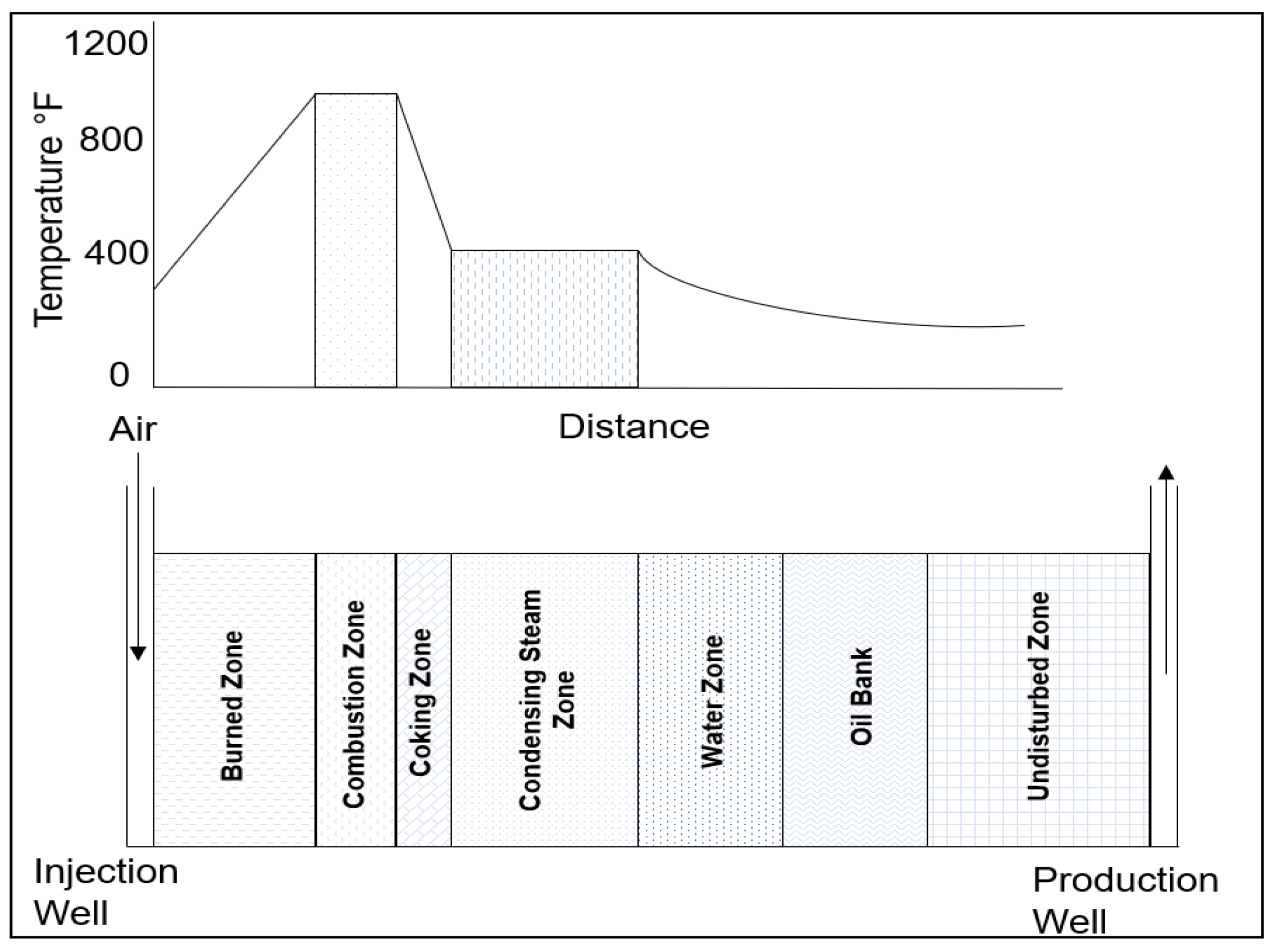
Figure 1. In situ combustion temperature profile and zones (adapted from Sarathi [4].)
Energies 16 06306 g001
Figure 2. THAI process schematic (adapted from Perkins [36]).
Energies 16 06306 g002
Figure 3. Reaction zones across the reservoir. LTO reactions occur furthest from the combustion front, MTO reactions promote fuel deposition, and the combustion front burns when HTO reactions occur [24].
Energies 16 06306 g003
Figure 4. Oxygen uptake rate with respect to temperature (adapted from Sur [64]).
Energies 16 06306 g004
Figure 5. Separation scheme for the original Athabasca bitumen and reaction products. (a) Adegbesan’s [60] solvent, and (b) Hayashitani et al. [70] solvent (adapted from Belgrave [69]).
Energies 16 06306 g005
Figure 6. General diagram of a combustion test apparatus [24].
Energies 16 06306 g006
Figure 7. Constituent parts of an ISC model (adapted from Storey et al. [24]).
Energies 16 06306 g007
Table 1. Comparison of dry forward combustion, wet forward combustion, and reverse combustion.
ISC
Mechanism
DefinitionApplied toAdvantagesDisadvantages
Dry Forward CombustionMost popular version of ISC. The combustion front is generated in situ. Same propagation direction of injected air and combustion front.Heavy oil reservoirs.The combustion provides the formation with a complete burning of formation, leaving the formation hydrocarbon-free.Limit viscosity reduction to recover hydrocarbons. Low heat is transferred from the combustion front to the downstream zones.
Wet Forward CombustionCombination of forward combustion and waterflooding. Addition of water or steam in the process.Thin reservoirs.Increases process efficiency. Improved heat transfer. Improved sweep efficiency.Simultaneous co-injection of both water and gas can be challenging.
ReverseThe combustion front is initiated at the production well and moves backward against the airflow.Reservoirs with low
effective permeability.
A significant amount of cracking occurs.Less upgraded oil is recovered. Spontaneous ignition near the injection well.
Table 2. Comparison of different combustion methods.
ISC MechanismDefinitionApplied toAdvantagesDisadvantages
THAICombines a vertical air injector + horizontal production well.Lower pressure, quality, thinner, and deeper than SAGD-fit reservoirs.Up to 80% of the OOIP recovery.
Oil upgrading up to 10° API.
Fewer surface facilities. More controllable process than ISC.
Negligible water use and less greenhouse gas emissions [33].
Challenging to control the combustion front movement and complexities associated with heterogeneities.
HPAIAir is injected into the reservoir at high temperature and pressure. Oxygen reacts with the hydrocarbons to improve mobility.Light oils in deep, thin, high-pressure reservoirs with low permeability.More reactions and more oxygen utilization,
High mobility ratios.
Possible high recovery factor, low air and energy requirements [24,43].
Possible air breakthrough at the production well.
CAPRIA variant of the THAI process. In situ refinery-type catalyst on the surface of the production well.For in situ upgrading of fluids, the economic viability needs to be assessed.Further upgrades the hydrocarbon in situ.Possible production of heavy metals and sulphur
COSHUtilizing gravity drainage as a driving mechanism. Incorporating multiple vertical injector wells in the upper region of the reservoir. The combustion front by oxygen injection propagates towards the production well beneath the injection wells.Thick reservoirs.Performance expected to be similar to that of SAGD.The effectiveness has not been definitively proven.
Uncertainties persist, highlighting the need for additional studies.
Table 3. Summary of kinetic reactions in in situ combustion.
Temperature RegionLow-Temperature ReactionsMedium Temperature Reactions (Negative Temperature Gradient Region)High-Temperature Reactions
Dominant oxidation modeOxygen-addition reactionsNo oxidation. Thermal cracking and pyrolysis take place.Bond-scission reactions (combustion reactions)
Reactionhydrocarbons + oxygen → oxygenated
species + coke + water
hydrocarbons → HC (liquid/solid) + HC (gas) + hydrogencoke + oxygen → short-chain HCs
+ CO + CO2 + water + energy
Temperature<300 °C280–350 °C380–800 °C
DescriptionOxygen dissolves in the oil, producing partially oxygenated hydrocarbons, further polymerizing and promoting the formation of emulsions and asphaltenes. LTO reactions also promote the formation of some of the fuel (oxygenated hydrocarbon) needed further in the process.Endothermic and homogeneous (gas-gas) reactions. Most of the coke (fuel)
is produced here.
These heterogeneous (gas–solid/gas–liquid) reactions occur at the combustion front. Oxygen reacts with unoxidized oil, coke, and oxygenated compounds to produce COx, water, and energy.
Table 4. Summary of in situ combustion testing methods: description, advantages, and limitations.
Type of TestDescriptionTest NameAdvantagesLimitations
Qualitative testsUsed for screening purposes. Qualitatively estimate kinetic parameters of oxidation reactions.TGA, DTA, DSC, PDSC, ARCThey are simple, quick, and inexpensive to perform.They do not provide any insight into the recovery performance. Not very realistic as only one reaction model is assumed.
Quantitative
tests
These studies replicate the flow conditions in the reservoir and determine the oxidation kinetics parameters. A reactor cell containing oil and sand is heated, the air is flown, and the residual oil and effluent gases are analyzed to determine the parameters that could be used in thermal reservoir simulators to predict field performance.RTOUseful for understanding and determining oxidation regimes (oxygen addition vs. bond scission).Does not reflect the same kinetic behavior observed during combustion tube tests due to peroxidation.
Combustion
performance
studies
Physical setup aimed at simulating and observing the advancement of a real combustion front within a reactor cell. Provides an understanding of the parameters affecting the combustion.Combustion tube testsUseful for understanding combustion parameters (air and fuel requirements, air-fuel ratio)Scaled experiments; upscaling is not a straightforward process.
Further details on these three tests follow.
Table 5. ISC screening guidelines based on information found in the literature.
Reference[3][9][42][15][114][4]
Formation characteristicsThe matrix/oil system is reactive enough to sustain combustion. Swelling clays may be a problem.Relatively uniform sandstone reservoir No presence of bottom waterHigh porosity sand/sandstoneLow clay content, low in minerals that promote increased fuel formation, such as pyrite, calcite, and siderite. Extensive fractures and strong water drive should be avoided at all costs.
Reservoir depthThere is no depth limit as long as the reservoir contains the air injected.>150 m (500 ft). <3500 m (11,500 ft). Current field projects’ average depth is approximately 1070 m (3500 ft).90–3800 m (300–12,500 ft)
Reservoir thicknessThe reservoir has to be at least 4 m (15 ft) in thickness to avoid excessive heat losses.>3 m (10 ft) >3 m (10 ft)>3 m (10 ft)1.5–15 m (5–50 ft)
TransmissibilityAir injectivity is favorable when the transmissibility is greater than 5 md m/cp. 16 md m/cp>20 md ft/cp>20 md ft/cp
Permeability >100 mD >100 mDAverage permeability > 50 mDNot critical
Porosity and oil saturationThe product, ϕSo, should be more than 0.08 for combustion to be economically successful.ϕ > 22%. The product, ϕSo, should be more than 0.13. Oil saturation greater than 50 percent. ϕ > 18%. The product ϕSo should be more than 0.07Oil saturation greater than 50%ϕ > 18%. The product ϕSo should be more than 0.09
Oil gravity and viscosityViscosity has to be low enough to allow air injection and resulting oil production at the design rate.24° API or less. μo < 1000 cpμo < 1000 cp (no need for CSS preheating)μo > 2000 cp (CSS becomes necessary)μo: 60–10,000 cp10–16° API. μo < 5000 cpμo < 5000 cp. Oil gravity 10–40° API
Oil characteristicsThe oil has to be readily oxidizable, as determined by laboratory experiments. Some asphaltic componentsLow asphaltic, low heavy metal content.
Disclaimer/Publisher’s Note: The statements, opinions and data contained in all publications are solely those of the individual author(s) and contributor(s) and not of MDPI and/or the editor(s). MDPI and/or the editor(s) disclaim responsibility for any injury to people or property resulting from any ideas, methods, instructions or products referred to in the content.