Article

Improving the Performance of an Innovative Centrifugal Pump through the Independent Rotation of an Inducer and Centrifugal Impeller Speeds

Arts et Métiers Institute of Technology LIFSE, Le Cnam, HESAM University, 75013 Paris, France
*
Author to whom correspondence should be addressed.
Energies 2023, 16(17), 6321; https://doi.org/10.3390/en16176321
Submission received: 12 July 2023 / Revised: 23 August 2023 / Accepted: 28 August 2023 / Published: 31 August 2023

Abstract

:
This article introduces an innovative design for a centrifugal pump featuring an inducer that enables the independent rotation of both the inducer and the centrifugal impeller. Unlike conventional designs, this configuration allows for differential speeds and customizable rotation directions, including co-rotation and counter-rotation modes. These new capabilities offer numerous operational advantages. This study investigates the impact of the speed ratio between the inducer and the impeller on the pump’s performance in both the co-rotation and counter-rotation modes. The results demonstrate that the independent rotation of the inducer expands the pump’s operating range, while counter-rotation significantly enhances the generation of pressure and the pump’s efficiency compared to co-rotation. These findings pave the way for the development of pumps that offer benefits such as a reduced size, reduced vibration, minimized energy consumption, and improved cavitation performance.

1. Introduction

Centrifugal pumps are essential in the oil and petroleum industries due to their adaptable design and compact structure [1,2]. To improve the Net Positive Suction Head Required (NPSHr) and prevent performance degradation, an axial impeller, known as an inducer, is positioned ahead of the primary centrifugal impeller [3]. This configuration effectively increases the inlet pressure of the impeller [4], thereby maintaining and optimizing performance at the nominal operating point. Centrifugal impellers equipped with inducers are utilized in various industries, including the nuclear [5], aircraft, and marine industries and in cryogenic propellant pumping [6].
Coutier-Delgosha et al. [7] conducted a numerical analysis to investigate the characteristics of a four-blade inducer under both cavitating and non-cavitating conditions. Guo et al. [8] demonstrated that the number of blades on the inducer significantly influences the pump’s head and its resistance to cavitation. According to their experimental findings, a three-blade inducer outperformed two-blade or four-blade inducers in terms of efficiency, pressure, and cavitation resistance. Additionally, Guo et al. [9] studied the effect of rotational speed on pump performance and found that increasing the rotational speed decreases its resistance to cavitation.
Magne et al. [10] conducted experimental investigations on a three-bladed inducer, focusing on the effects of dissolved CO2 and jet fuel on its performance. The study showed that the concentration of CO2 had a minimal impact on the inducer’s efficiency under non-cavitating conditions but had a significant effect in the presence of cavitation. Bakir et al. [11] successfully developed a two-phase cavitation model for inducers and validated it through laboratory tests. Their model demonstrated good agreement and correlation with the laboratory findings in terms of the drop in pressure and the identification of cavitation pockets.
Although the addition of an inducer to the centrifugal impeller enhances the hydraulic performance of the pump, it results in a 20% decrease in the total pressure generated by the pump at a flow rate of 60% of the nominal flow rate due to the generation of pre-rotation [12]. Research on the impact of the radial height of a helical static blade on inducer cavitation performance has shown that the efficiency of the inducer decreases as the radial height of the helical static blade increases within specific ranges [13].
A visual experimental investigation conducted by Xu et al. [14] on a high-speed inducer revealed the development of a vortex at the inducer’s inlet rotating at half of the inducer’s speed. The volume of the backflow vortex decreased with the flow rate and disappeared completely at flow rates greater than 30% of the design flow rate. Campos-Amezcua et al. [15] investigated the cavitating flow through an axial two-bladed inducer, considering the effect of tip clearance. Based on a performance analysis of a centrifugal pump with variable pitch inducers operating at different speeds [9], it was observed that the static head increases with the rotational speed. However, higher rotational speeds also lead to an increase in the Net Positive Suction Head Required (NPSHr), indicating a higher risk of cavitation in the pump.
Kim et al. [16] examined the impact of existing inducers on centrifugal impellers. They found that under non-cavitating conditions, inducers enhance the head and efficiency at low flow rates. However, at high flow rates, they decrease both the head and efficiency. Numerical investigations into the matching between the inducer and the impeller indicate that as the distance between them increases, the distribution of bubbles becomes more uniform, improving the pump’s cavitation performance. However, it is important to note that at high angles of attack, there is a decrease in pressure due to circumferential deflection [17].
Typically, centrifugal pumps have the inducer and the impeller integrated on a single shaft, limiting them to the same rotational direction and speed. However, in recent years, there has been a growing demand for efficient and reliable turbomachines, prompting scientists and industries to explore alternative designs beyond conventional single-blade turbomachines. One design that has garnered significant attention is the counter-rotating turbomachine. The shift towards counter-rotating configurations is driven by the recognition that they offer improved performance and operational characteristics compared to single-blade turbomachines.
Tosin et al. [18] conducted experimental investigations on a counter-rotating mix flow pump. Two prototypes of the counter-rotating pump were developed to improve the cavitation behavior, which was achieved by redesigning the front rotor while keeping the rest of the system constant. Another study by Tosin et al. [19] explored a new counter-rotating approach using mixed and radial flow pumps for the first and second rotor, respectively. Both rotors were developed using a streamline curvature analysis, and the Response Surface Method (RSM) was employed for optimization. An auto-adaptive approach capable of independently varying the speed of each rotor to achieve the highest performance was presented. The front rotor operated in a speed range of 1200 to 1450 rpm, while the rear rotor operated in counter-rotation mode in a range of speeds from 0 to 1048 rpm. The RSM results provided an optimum design by combining the design speeds and pressure ratios of both rotors.
Pavlenko et al. [20] conducted a numerical study on the effect of the impeller trim in a counter-rotating centrifugal pump. They investigated various counter-rotating impellers and found that the pump’s pressure is influenced by the impeller trim and the size of the working part of the impeller. Relatively low amounts of impeller trim increased the pressure, although the energy efficiency decreased.
Chen et al. [21] examined the impact of geometric parameters, such as the blade angle, on the characteristics of a counter-rotating axial pump with a rotational speed of 1480 rpm for both rotors. The results showed that decreasing the outlet angle while maintaining the inlet angle resulted in decreased flow rate, which had an impact on the pump’s efficiency.
In general, the employment of counter-rotating turbomachines aids in improving their performance and efficiency. Rajeevalochanam et al. [22] obtained an increase of up to 2% in efficiency in a wide range of pressure ratios and a 23% reduction in the overall weight of the turbine by using a counter-routing turbine in the low-pressure stage of the turbine. The design of a counter-rotating turbine for a turbo-compounding system by Zhao et al. [23] resulted in a 3.8% increase in the turbine’s power efficiency at a rotational speed of 1200 rpm. The challenges associated with counter-rotation turbomachines were studied and analyzed by Ji [24], who demonstrated that a new approach based on the velocity triangle can be used in these machines. The performance improves at certain rotational speeds while deteriorating at others.
In recent years, there has been an increasing number of studies focused on counter-rotating pumps. While axial pumps have received more attention in these studies compared to centrifugal pumps, there has not been any specific research conducted on the inducer and impeller yet. This article presents a novel experimental test bench that enables the independent rotation of the inducer and the centrifugal impeller. This unique capability allows for the investigation of the effects of the inducer’s rotation at different speed ratios and the direction of the inducer’s rotation (in co-rotation and counter-rotation modes) on the pump’s characteristics.
Alongside research on centrifugal pumps, it is worth noting that various other types of pumps, including axial piston pumps and flexible electrohydrodynamic pumps, have also received extensive attention [25,26]. These pumps are commonly used in hydraulic systems to convert mechanical rotational power into hydraulic power. Similar to the centrifugal pumps discussed here, axial piston pumps encounter comparable challenges relating to optimizing their performance, handling cavitation, and managing rotational speed [25]. The researchers of this paper utilized this feature to analyze how the speed ratio between the inducer and the centrifugal impeller and the direction of the inducer’s rotation impact the pump’s characteristics. In addition, numerical simulations of the impeller and inducer were conducted and compared to the experimental results to study the flow field between the inducer and the impeller, as well as to measure the pressure generated independently by the inducer and impeller in various operational modes.
The findings of this study emphasize the significant influence of the direction of the inducer’s rotation and speed ratio on the performance of the pump. The results highlight that these parameters have a significant effect on the overall performance of the pump.

2. Experimental Test Bench and Pump Description

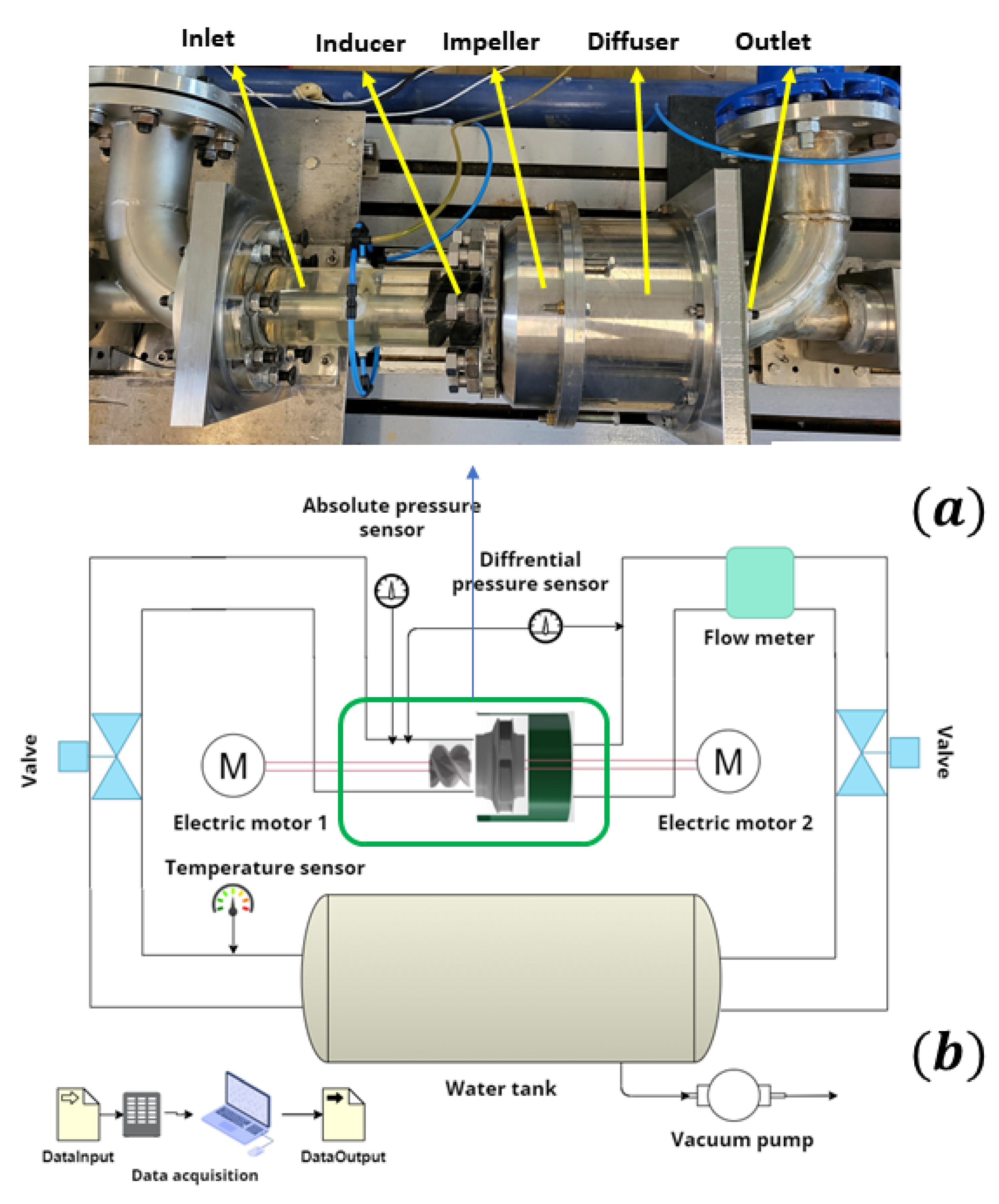
2.1. Experimental Test Bench

A novel experimental test bench, developed at the Laboratory of Fluid Engineering and Energy Systems (LIFSE) in Arts et Métiers Paris, features the independent rotation of the inducer and impeller. Figure 1 provides a schematic of the newly designed test bench, which consists of two main sections: the inducer section and the impeller section. Unlike traditional pumps in which the impeller and inducer are positioned on a single shaft, rotating at the same speed and direction, the configuration in this test bench is different. Here, the inducer and impeller are situated on separate shafts which are located one behind the other, and they rotate completely independently in terms of speed and direction.
The impeller and inducer sections are assembled separately, allowing for the easier replacement of both components. To achieve independent rotation, the inducer is positioned on a separate shaft extending from the opposite side to the front of the impeller, as shown in Figure 1. The inducer is driven by a 4 kW ABB motor with a maximum speed of 3500 rpm. An ABB frequency drive with a power range of 5 kW is used to control the rotational speed and direction of the inducer. For the higher power demands of the impeller, a 30 kW Dietz motor is installed. The speed and direction of the rotation of the motor are controlled by a Danfoss frequency drive with a power range of 35 kW.
To prevent the direct entry of the flow into the system, an elbow is used in the water inlet. The test bench operates within a closed circulation system which includes a 1000 L water tank, a vacuum pump and a flow meter located at the outlet of the pump. The vacuum pump is connected to the tank to decrease the pressure at the inlet of the inducer for cavitation testing. The flow rate is measured by the flow meter, which has a measurement accuracy of 0.6 m3/h and a measuring capacity of 282 m3/h. The water temperature is measured using a resistance temperature detector (RTD) thermometer.
Considering the uncertainties of each sensor, the uncertainty for the efficiency is determined to be 1.2%, which is within an acceptable range. The results obtained from the cavitation tests conducted on this setup will be discussed and analyzed in future studies.
The pressures generated by the inducer and impeller are measured using a differential pressure transducer with a range of 0 to 3 bar and a measuring accuracy of 0.1%. Additionally, an absolute pressure transducer is installed upstream at a distance equal to the diameter of the inducer to measure the absolute pressure. To facilitate visualization, the inducer is placed inside a transparent plexiglass tube. The test bench includes a slider mechanism that allows for the easy displacement of the inducer section, enabling the convenient replacement of both the inducer and impeller. By utilizing plexiglass tubes of varying lengths, it is possible to adjust the distance between the inducer and impeller. The outcomes and findings resulting from these adjustments will be thoroughly analyzed and discussed in future investigations.

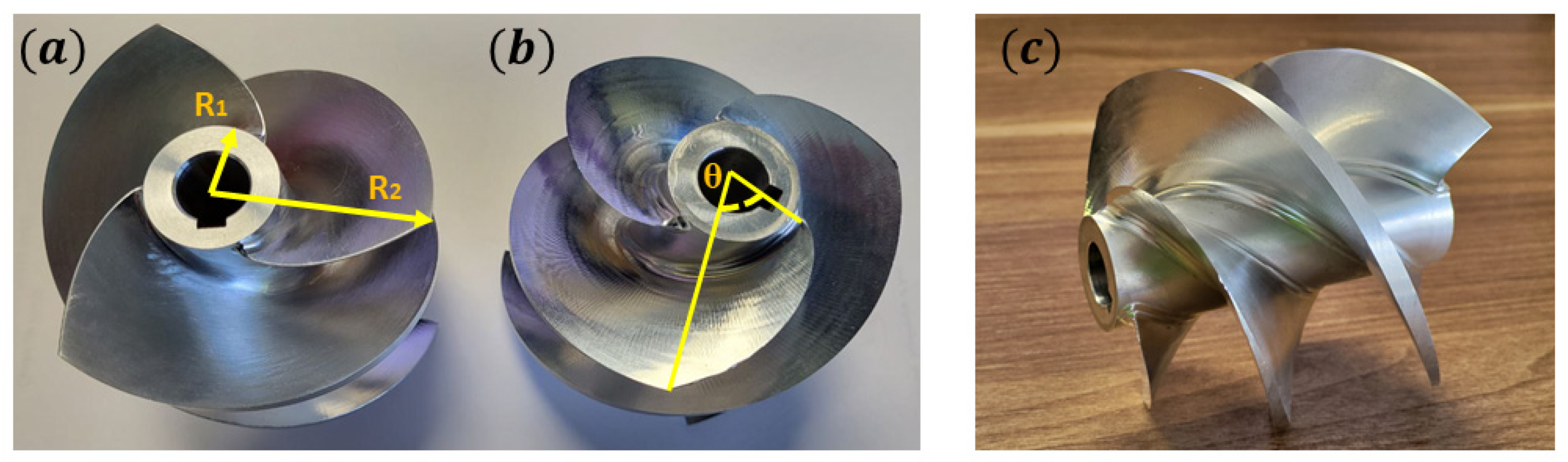
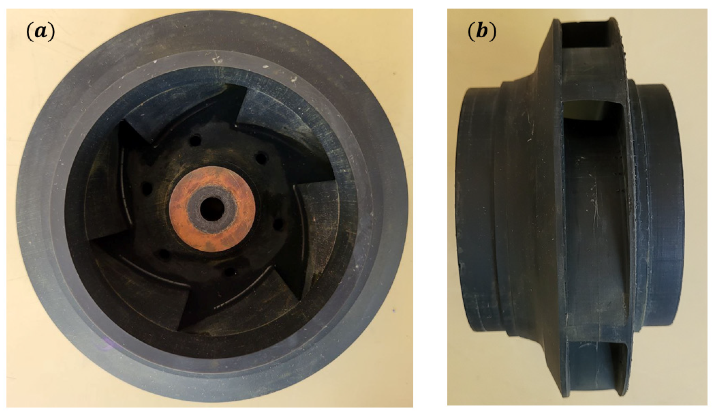
2.2. Inducer and Impeller Parameters

This research involved the use of two inducers and one centrifugal impeller. Both inducers had the same geometry but opposite angles of attack. One of the inducers rotated in the same direction as the centrifugal impeller (co-rotation mode), while the other inducer rotated in the opposite direction of the centrifugal impeller (counter-rotation mode). Table 1 presents the specific characteristics of the inducer where R 1 , R 2 , θ, S h , and S t represent the internal radius, external radius, sweep angle, hub solidity, and tip solidity of the inducer, respectively. Figure 2 illustrates both the co-rotative and counter-rotative inducers. To reduce weight and prevent shaft bending and vibration at high speeds, the inducer is made of aluminum 6062, given the long shaft used in the inducer section.
Figure 3 depicts the six-blade closed centrifugal impeller manufactured using a stereolithography printer (SLA printer). An SLA printer is a specific type of 3D printer that utilizes the stereolithography technique to create three-dimensional objects from liquid resin. In this case, the printing process utilized black standard resin, known for its excellent mechanical properties and high-quality surface finish, both of which are crucial for ensuring the impeller’s functionality.
Table 2 presents the blade specifications for the centrifugal impeller. The parameters D 1 , b 1 , and β 1 correspond to the blade inlet diameter, blade inlet width, and blade angle at the inlet, respectively. Similarly, D 2 , b 2 , and β 2 correspond to the blade outlet diameter, blade outlet width, and blade angle at the outlet, respectively.
The impeller and inducer were designed to reach their Best Efficiency Point (BEP) at different rotational speeds. The inducer was designed for a rotational speed of 2400   rpm ( n 1 ), while the impeller was designed for a rotational speed of 2000   rpm ( n 2 ). The ratio between the rotational speeds of the inducer and impeller is referred to as the speed ratio ( S R = n 1 n 2 ). Both components were optimized to operate at a flow rate of 40   m 3 / h in in order to achieve the highest efficiency.

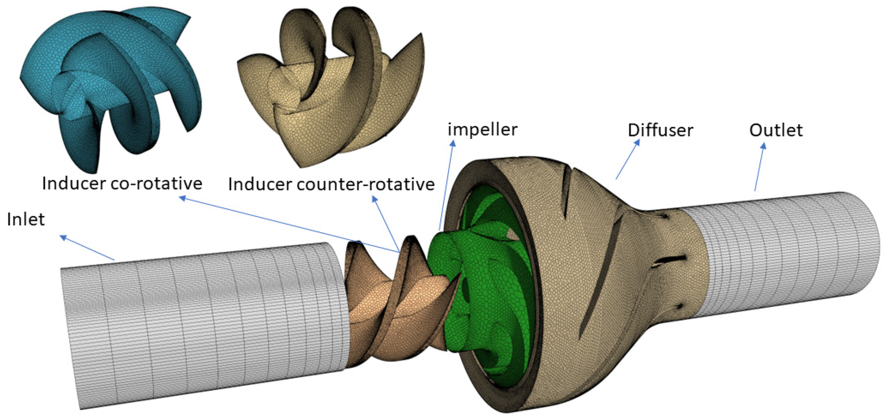
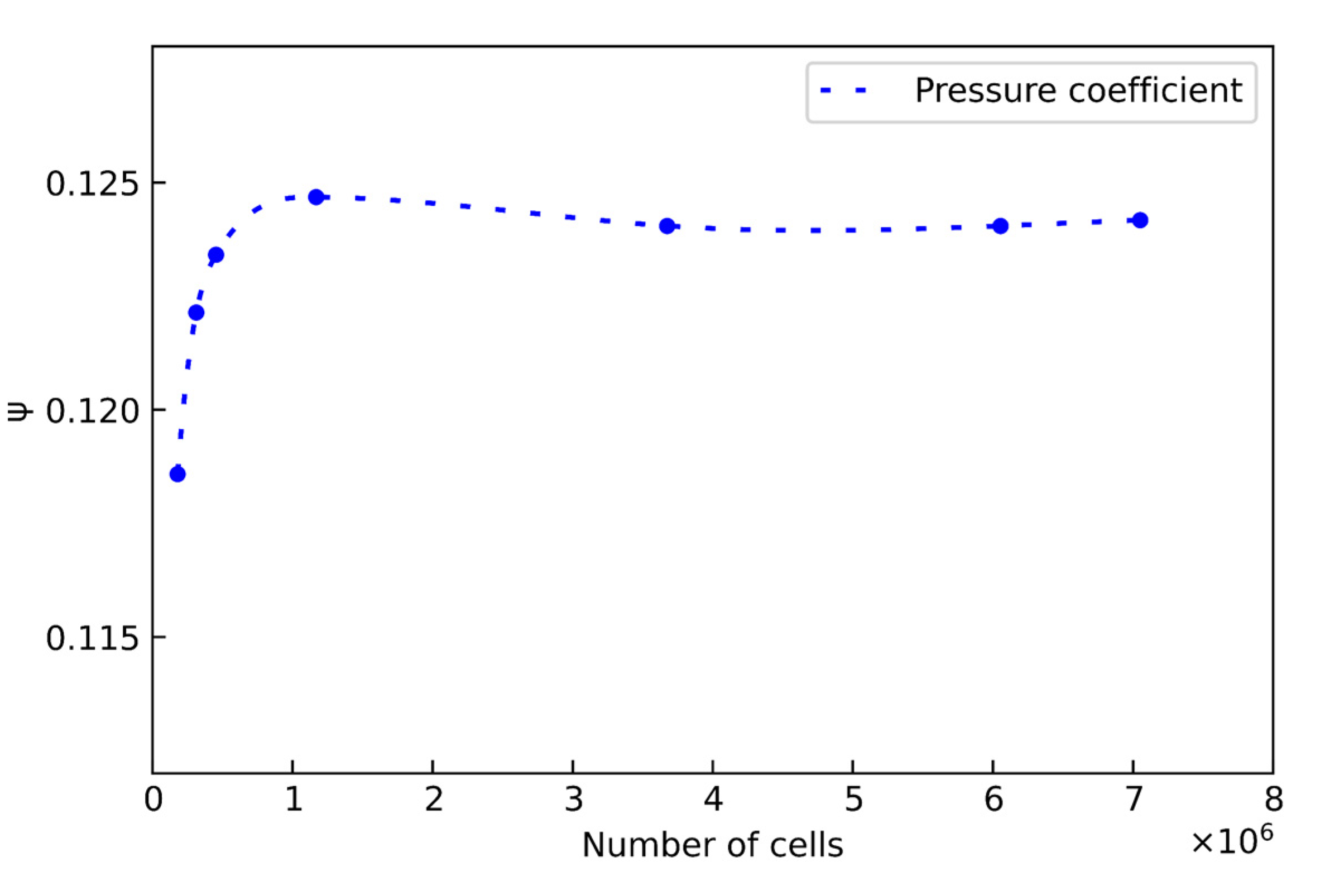
3. Numerical Simulation

A numerical simulation was used to study the interaction between the inducer and impeller, as well as the individual effects of each rotor on the characteristics of the pump like the pressure produced by each rotor independently, which is not accessible experimentally due to experimental limitations. The CFD simulation was carried out using StarCCM+ 16.06 software. The steady state Reynolds-Averaged Navier–Stokes (RANS) equations were solved using the realizable k-ɛ model as the turbulence model. A constant pressure was chosen for the boundary condition at the inlet, and its value was adjusted to 1 bar absolute, which is equivalent to the pressure of the experimental system. In order to cover the range of flow rates in the experimental tests, the boundary condition in the output was adjusted to variable flow rate, and a range of flow rates varying between 0 and 60 m 3 / h was considered To achieve the highest level of accuracy for the new independent rotating arrangement, its complete geometry must be simulated. According to the new system of independent rotation, each of the rotors was defined as a separate rotating part, which includes the two parts called the inducer and the impeller. This made it possible to apply different rotational speeds and to change the direction of the rotation of the inducers. Water with constant density of 997.56   kg / m 3 was used as the working fluid during the simulations, similar to the conditions of the experimental tests. A three-dimensional steady-state flow with a constant density was considered the flow model during the simulation [27].
Considering the potential for a high computational cost, selecting the right mesh is an essential part of every simulation. The mesh must be precise enough to satisfy the simulation’s requirements without increasing the computation time or cost. To accomplish this, it is necessary to check the mesh’s independence to ensure that the mesh contains a sufficient number of cells to produce accurate results without requiring a significant computing cost. In this work, the optimal number of mesh cells was determined by analyzing the pressure sensitivity of seven different meshes. The various components of the geometry with the mesh applied are shown in Figure 4. The simulated geometry was divided into several parts, including an inlet, co-rotative and counter-rotative inducers, a centrifugal impeller, a diffuser, and an outlet. Table 3 shows the number of mesh cells applied to each part of the simulated geometry.
Figure 5 illustrates the variations in pressure for the counter-rotation mode with S R = 1.2 at BEP across different meshes. Based on the mesh geometry, mesh number 5 was identified as the optimal choice for this study. In this study, an unstructured polyhedral mesh was employed. The mesh base size was set at 20   mm . To enhance accuracy, four prism layers with a size of 2% of the base were added to the tip of the inducer, while six prism layers of the same size were applied to the impeller. Surface controls were considered in various parts of the mesh to optimize computational costs and improve accuracy. The minimum and maximum mesh sizes within these surface controls ranged between 1% and 5% of the base size. This approach ensured that unnecessary small meshes were not generated in non-critical areas, preventing an increase in the overall number of meshes and the computational cost. Simultaneously, it increased the accuracy of the calculations to the desired levels. The y+ values range from 0.22 to 4.49, demonstrating precise velocity gradient within the walls. To be able to simulate rotating objects, due to the complex geometry, the Multiple Reference Frame (MRF) method was used. Three main interfaces between the inducer inlet and the inlet area, the inducer outlet and the impeller inlet, and the impeller outlet and the diffuser inlet were defined. A segregated flow with upwind convection scheme of second-order accuracy was used.

4. Results and Discussion

4.1. Study Parameters

The system’s ability to separate the rotation of the two rotors allows for the study of two parameters: the SR and the inducer’s rotational direction (Table 4). The two inducers were built with identical geometrical properties and inverse tip angles to rotate in both co-rotation and counter-rotation modes. The n 2 was fixed equal to 2000   rpm in this research. According to the similarity rules and dimensional analysis, the following dimensionless numbers were introduced for rest of this study:
φ = g H n 2 2 D 2             Ψ = g H n 2 2 D 2
where D , Ψ , and φ are impeller diameter, pressure coefficient, and flow coefficient, respectively.

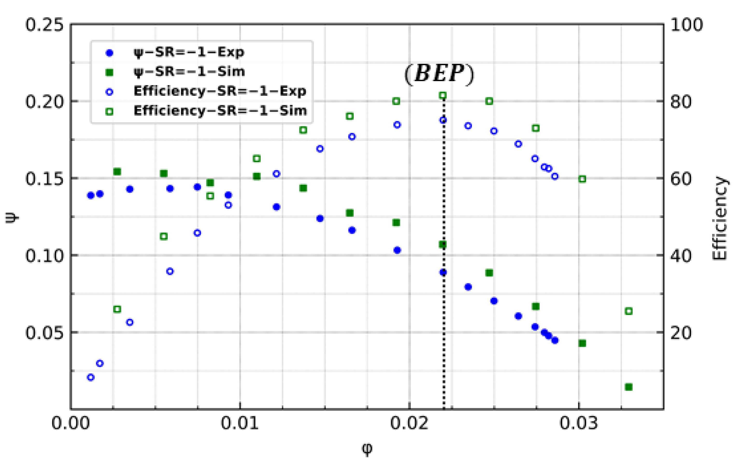
4.2. Comparison of Experimental and Numerical Results

Figure 6 illustrates the comparison between the experimental and numerical results for the counter-rotation mode at S R = 1 . The experimental results include both the test outcomes and the mechanical loss of the system. To determine the mechanical loss resulting from components like bearings and mechanical seals, the impeller and inducer were removed from the shafts. The shafts were then rotated without these components, and the power consumption of each section (inducer and impeller) was measured. This allowed for the calculation of the mechanical loss caused by the bearings and mechanical seals in the system. The experimental and simulation results demonstrate a good correlation, with a difference of approximately 5%. This difference can be the result of additional losses within the experimental system, primarily the hydraulic loss. The hydraulic loss is notable due to the presence of two elbows at the pump’s inlet and outlet, as well as a support for the inducer shaft upstream. Due to the high computational cost involved, the simulation does not consider these elbows and supports that are part of the system. Consequently, a slight variation between the experimental results and the simulation results is observed.

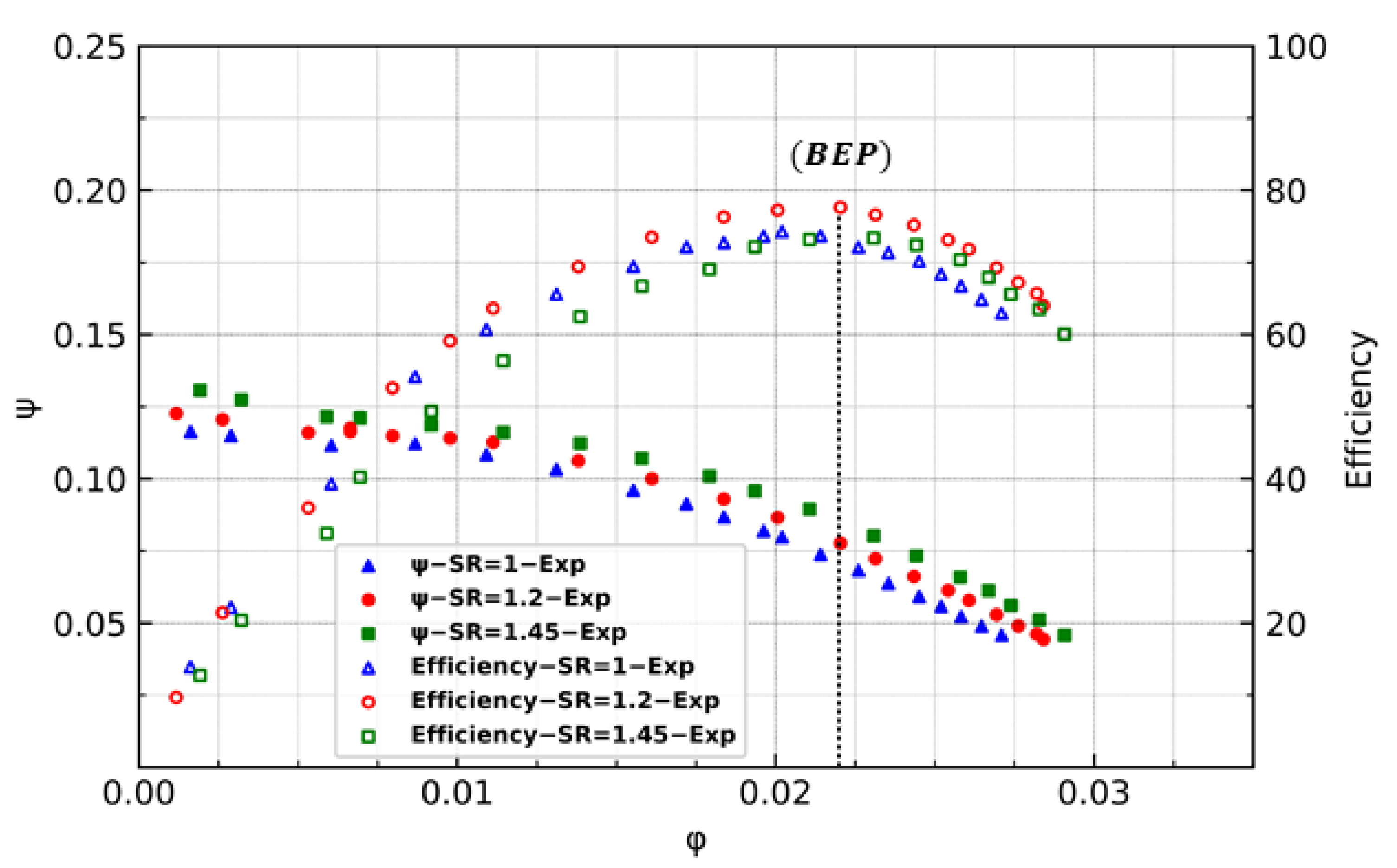
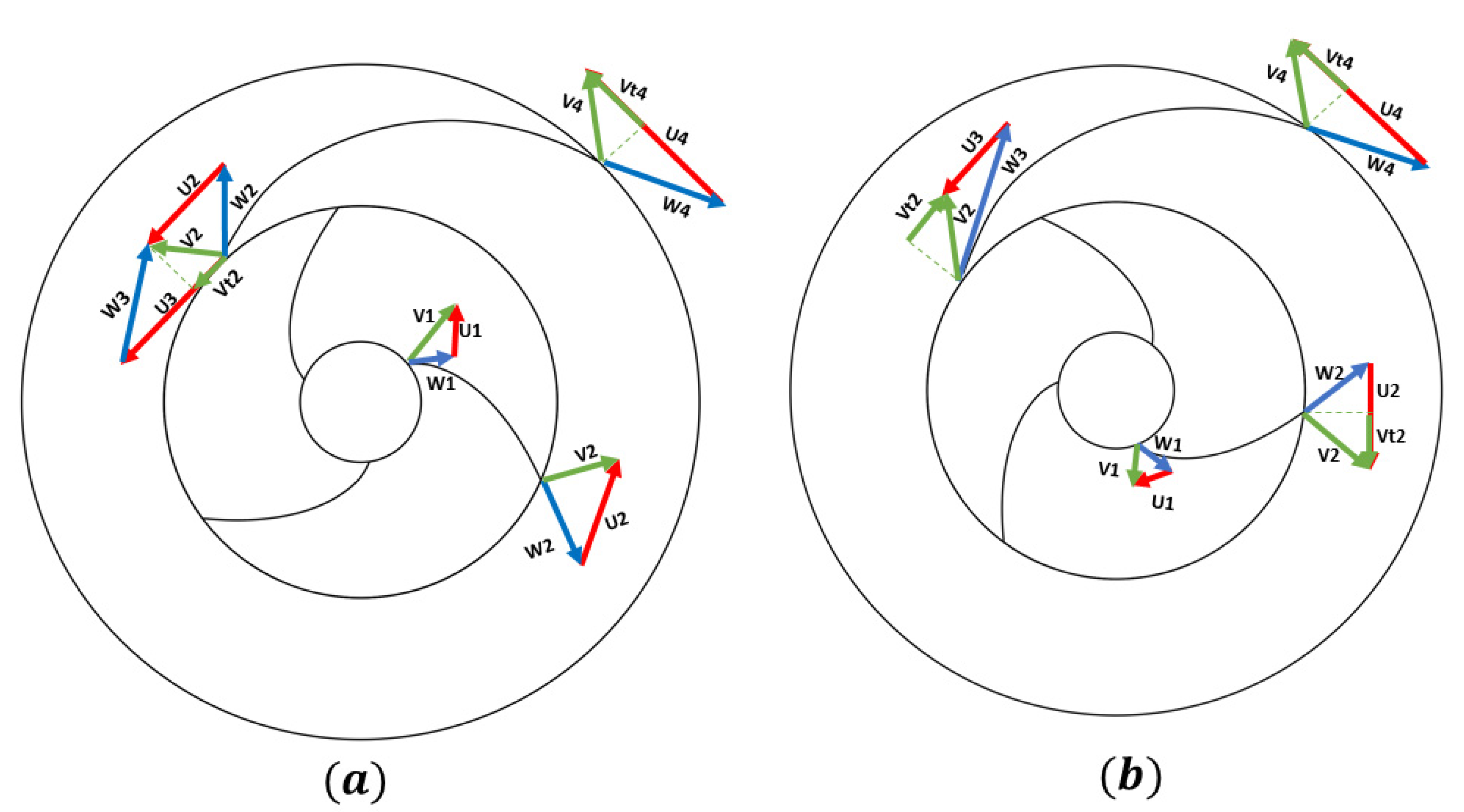
4.3. Characteristics in Co-Rotation Mode

Figure 7 shows the experimental results of the pump in the co-rotation mode with various SRs. The working area of the pump can be divided into three main areas. The point at which the pump works with the highest efficiency is known as the BEP; in this study, the BEP is present at φ = 0.022 . The region in which the flow rate is lower than the flow rate of the BEP is referred to the low-flow-rate area (LFR), and the region in which the flow rate is higher than the flow rate of the BEP is called the high-flow-rate area (HFR).
The impact of the S R on the pump’s pressure can be observed in all three areas. It is evident that as the S R increases, the pump exhibits an enhanced capacity to generate pressure. This is primarily due to the higher rotational speed of the inducer, which results in an increase in pressure production. Although increasing the speed of the inducer increases the pump’s pressure, it also creates a pre-whirl in the fluid as it enters the impeller. This pre-whirl, in accordance with the Euler equation, reduces the generation of pressure by the impeller. However, the overall pressure continues to increase because the pressure generated by the inducer surpasses the pressure drop within the impeller caused by the pre-whirl of the fluid at the inlet. As the flow rate increases, the pressure drop in the impeller caused by the pre-whirl of the flow at the inlet of the impeller also increases. The pressure difference between the S R = 1.45 and S R = 1 reduces with higher flow rates, according to Figure 7. However, it is important to note that regardless of this observation, an increase in the S R consistently has a positive impact on the overall pressure. The relationship between the efficiency and S R indicates that although increasing the speed of the inducer raises the pressure, it can have an opposite effect on the system’s efficiency. In the LFR region, the efficiency is nearly equivalent at S R = 1 and S R = 1.2 , but it decreases for S R = 1.45 . As the flow rate approaches the BEP, the efficiencies at S R = 1 and S R = 1.45 become similar, but the efficiency at S R = 1.2 remains slightly higher. In the HFR region, it is evident that the efficiencies of S R = 1.45 and S R = 1.2 surpass the efficiency at S R = 1 .

4.4. Effects of the Counter-Rotation Mode

Figure 8 provides a visual representation of the pressure distribution within the inducer for both the co-rotation and counter-rotation modes for S R = ± 1 . The pressure contour reveals that the pressure distribution is relatively similar in both cases, with a noticeable drop in the localized pressure at the tip of the inducer. The pressure drop observed at the tip of the inducer increases the potential for cavitation, specifically tip vortex cavitation at high-speed rotation. This phenomenon and its implications will be further examined and discussed in upcoming studies.
Figure 9 illustrates the numerical results of the pressure produced by the inducer in both co-rotation and counter-rotation modes at S R = ± 1.45 at the BEP. The primary objective of using the inducer is to enhance the pressure at the inlet of the impeller. It can be found that changing the direction of rotation of the inducer does not have an impact on the pressure generated by the inducer itself, according to Figure 9. However, the pressure produced by the impeller increases, subsequently leading to an overall increase in the pump’s total pressure. It demonstrates that only the inducer has an effect on the impeller, while the impeller has no impact on the inducer.
In Figure 10, the velocity triangles for both the co-rotation and counter-rotation modes are presented. The diagram represents various parameters: U represents the speed of the rotor (either the impeller or the inducer) and is defined as U = r ω , where r is the distance to the center of rotation and ω is the rotational speed of the rotor, V represents the absolute velocity of the flow, and W represents the relative velocity of the flow.
According to Euler’s turbomachinery equations [28], the theoretical head ( H t h ) generated by the impeller can be determined using the following equation:
H t h = ( U 4 V t 4 U 3 V t 3 ) g
where V t represents the tangential velocity of the flow. The flow leaving the inducer is equal to the flow entering the impeller, so V t 2 = V t 3 , and based on the velocity triangle (Figure 10), it is apparent that in the co-rotation mode, U 3 and V t 3 are in the same direction, resulting in a positive value for U 3 V t 3 , but in the counter-rotation mode, the direction of V t 3 is opposite to the direction of U 3 and the above equation becomes the following equation for the counter-rotation mode:
H t h C R = ( U 4 V t 4 + U 3 V t 3 ) g
where H t h C R presents the theoretical head of the pump in the counter-rotation mode. The total pressure is higher in the counter-rotation mode compared to the co-rotation mode.
Figure 11 demonstrates the impact of the direction of the inducer’s rotation on the pump’s efficiency and pressure at the same S R . The results indicate that the direction of the rotation significantly affects the pump’s pressure. It is observed that the pump generates a higher level of pressure when the inducer rotates in the counter-rotation mode, while the efficiency is not significantly affected. In the LFR region, the efficiency is slightly lower compared to the co-rotation mode, but at the BEP, the counter-rotation mode achieves a higher level of pressure with same efficiency. This trend continues in the HFR region, in which the counter-rotation mode achieves higher levels of efficiency and pressure.
Figure 12 illustrates the impact of the S R on the pump’s characteristics in the counter-rotation mode. The trends in efficiency and the changes in pressure with the flow rate are similar to those observed in the co-rotation mode. However, it can be observed that the effect of the S R on the pump’s pressure is more pronounced in the counter-rotation mode compared to the co-rotation mode. This effect can be identified from the significant difference in the pressure diagrams. For example, at the BEP and for S R = ± 1.45 , the counter-rotation mode generates a significantly higher pressure than the co-rotation mode while maintaining the same efficiency.
In the HFR region, the pressure is still influenced by the S R in the counter-rotation mode, unlike in the co-rotation mode. This difference comes from the reverse pre-rotation of the fluid caused by the inducer’s reverse rotation in the counter-rotation mode.

5. Conclusions

This article presents the results of an innovative experimental method of studying the impact of the independent rotation of the inducer and impeller in a pump. This article focuses on both numerical and experimental investigations for evaluating the impact of two new parameters that can only be modified when the inducer and impeller are independently rotated. These parameters include the S R between the inducer and impeller, as well as the direction of the rotation of the inducer. The three S R values ( S R = ± 1 ,   ± 1.2 ,   and   ± 1.4 ) for two co-rotation and counter-rotation modes have been investigated. The results indicate that increasing the inducer speed and raising the S R from 1 to 1.45 can enhance the pressure ratio at the BEP of the pump by 18% in the co-rotation mode. The counter-rotation produces a 20% increase in pressure over the co-rotation mode in the pump simply by switching the inducer’s direction of rotation while keeping the same speeds of the inducer and impeller. Furthermore, in the counter-rotation mode, S R = 1.45 results in a 27% increase in the pump’s pressure compared to the   S R = 1 . It can be concluded that an increase in the S R results in an increase in the pump’s pressure, but this effect is significantly greater in the counter-rotation mode. Furthermore, by using two inducers with same geometrical specifications but opposite angles of attack and the ability to rotate the pump in a counter-rotation mode, a noticeable increase in the pump’s pressure is achieved. In the case of the same S R , counter-rotation provides a 30% greater increase in pressure at the BEP compared to co-rotation.
Overall, it can be found that for a pump that includes an inducer and an impeller that work at a specific operating point, counter-rotating the pump has the ability to achieve the same characteristics of conventional pumps with a lower rotational speed or a smaller size. A pump with a separately rotating inducer and impeller provides increased hydraulic efficiency and operating flexibility. This pump design may achieve better performance and may be easily adapted to varied operating conditions by using pre-swirl and independent rotor control. The cavitation performance of this innovative type of pump will be examined in future works.

Author Contributions

Conceptualization, F.B. and E.D.; methodology, F.B. and E.D.; software, E.D.; validation, M.S., A.D., F.B. and M.K.; formal analysis, E.D.; investigation, E.D. and F.B; data curation, E.D.; writing—original draft preparation, E.D.; writing—review and editing, E.D., A.D. and F.B.; supervision, F.B.; project administration, F.B. All authors have read and agreed to the published version of the manuscript.

Funding

This research received no external funding.

Data Availability Statement

The data are not available to the public.

Acknowledgments

This research was carried out at the LIFSE laboratory in collaboration with the FAPMO. The authors would like to acknowledge the FAPMO and LIFSE for their support in the completion of this research, particularly in the experimental tests.

Conflicts of Interest

The authors declare no conflict of interest.

Nomenclature

R 1 Internal radius of inducer (mm)
R 2 External radius of inducer (mm)
θ Sweep angle of inducer ( ° )
S h Hub solidity of inducer
S t Tip solidity of inducer
D 1 Inlet diameter of impeller (mm)
b 1 Inlet blade width of impeller (mm)
β 1 Inlet blade angle of impeller ( ° )
D 2 Outlet diameter of Impeller (mm)
b 2 Outlet blade width of impeller (mm)
β 2 Outlet blade angle of impeller ( ° )
S R Speed ratio
n 1 Rotational speed of inducer (rpm)
n 2 Rotational speed of impeller (rpm)
Ψ Pressure coefficient
φ Flow coefficient
L F R Low Flow Rate
B E P Best Efficiency Point
H F R High Flow Rate
U Speed of rotor ( m / s )
V Absolute velocity of flow ( m / s )
r Radius of rotor (m)
ω Angular speed of rotor ( 1 / s )
H Static head of pump (m)
H t h Theoretical head of pump (m)
H t h C R Theoretical head of counter-rotation pump (m)

References

  1. Mansour, M.; Wunderlich, B.; Thévenin, D. Effect of tip clearance gap and inducer on the transport of two-phase air-water flows by centrifugal pumps. Exp. Therm. Fluid Sci. 2018, 99, 487–509. [Google Scholar] [CrossRef]
  2. Japikse, D.D. Overview of industrial and rocket turbopump inducer design. In Proceedings of the CAV 2001: Fourth International Symposium on Cavitation, Pasadena, CA, USA, 20–23 June 2001. [Google Scholar]
  3. Liquid Rocket Engine Turbopump Inducer. Available online: https://ntrs.nasa.gov/api/citations/19710025474/downloads/19710025474.pdf (accessed on 31 May 2023).
  4. Hong, S.-S.; Kim, D.-J.; Kim, J.-S.; Choi, C.-H.; Kim, J. Study on inducer and impeller of a centrifugal pump for a rocket engine turbopump. Proc. Inst. Mech. Eng. Part C J. Mech. Eng. Sci. 2013, 227, 311–319. [Google Scholar] [CrossRef]
  5. Koishikawa, A.; Takeuchi, Y.; Ohta, S. Development of Advanced Inducer Pump for LMFBR; Atomic Energy Society of Japan: Tokyo, Japan, 1992. [Google Scholar]
  6. Semenov, Y.A.; Fujii, A.; Tsujimoto, Y. Rotating Choke in Cavitating Turbopump Inducer. J. Fluids Eng. 2004, 126, 87–93. [Google Scholar] [CrossRef]
  7. Coutier-Delgosha, O.; Morel, P.; Fortes-Patella, R.; Reboud, J. Numerical Simulation of Turbopump Inducer Cavitating Behavior. Int. J. Rotating Mach. 2005, 2005, 135–142. [Google Scholar] [CrossRef]
  8. Guo, X.; Zhu, Z.; Cui, B.; Shi, G. Effects of the number of inducer blades on the anti-cavitation characteristics and external performance of a centrifugal pump. J. Mech. Sci. Technol. 2016, 30, 3173–3181. [Google Scholar] [CrossRef]
  9. Guo, X.; Zhu, Z.; Shi, G.; Huang, Y. Effects of rotational speeds on the performance of a centrifugal pump with a variable-pitch inducer. J. Hydrodyn. 2017, 29, 854–862. [Google Scholar] [CrossRef]
  10. Magne, T.; Paridaens, R.; Khelladi, S.; Bakir, F.; Tomov, P.; Pora, L. Experimental Study of the Hydraulic Performances of Two Three-Bladed Inducers in Water, Water with Dissolved CO2, and Jet Fuel. J. Fluids Eng. 2020, 142, 111210. [Google Scholar] [CrossRef]
  11. Bakir, F.; Rey, R.; Gerber, A.; Belamri, T.; Hutchinson, B. Numerical and Experimental Investigations of the Cavitating Behavior of an Inducer. Int. J. Rotating Mach. 2004, 10, 15–25. [Google Scholar] [CrossRef]
  12. Fu, Y.; Xie, J.; Shen, Y.; Pace, G.; Valentini, D.; Pasini, A.; D’Agostino, L. Experimental and numerical study on cavitation performances of a turbopump with and without an inducer. Proc. Inst. Mech. Eng. Part G J. Aerosp. Eng. 2022, 236, 1098–1111. [Google Scholar] [CrossRef]
  13. Bi, C.; Li, J. Effect of Radial Height of Helical Static Blade on the Cavitation Performance of Inducer. Appl. Sci. 2022, 12, 3897. [Google Scholar] [CrossRef]
  14. Xu, Z.; Kong, F.; Zhang, H.; Zhang, K.; Wang, J.; Qiu, N. Research on Visualization of Inducer Cavitation of High-Speed Centrifugal Pump in Low Flow Conditions. J. Mar. Sci. Eng. 2021, 9, 1240. [Google Scholar] [CrossRef]
  15. Campos-Amezcua, R.; Khelladi, S.; Mazur-Czerwiec, Z.; Bakir, F.; Campos-Amezcua, A.; Rey, R. Numerical and experimental study of cavitating flow through an axial inducer considering tip clearance. Proc. Inst. Mech. Eng. Part A J. Power Energy 2013, 227, 858–868. [Google Scholar] [CrossRef]
  16. Kim, C.; Choi, C.-H.; Kim, S.; Baek, J. Numerical study on the effects of installing an inducer on a pump in a turbopump. Proc. Inst. Mech. Eng. Part J. Power Energy 2021, 235, 1877–1891. [Google Scholar] [CrossRef]
  17. Wang, D.; Gao, B.; Chen, Y.; Pan, Y.; Luo, J.; Liu, L.; Wei, Q.; Liu, L. Effects of Matching between the Inducer and the Impeller of a Centrifugal Pump on Its Cavitation Performance. Machines 2023, 11, 142. [Google Scholar] [CrossRef]
  18. Tosin, S.; Friedrichs, J.; Dreiss, A. New Design Approach for a Highly Loaded Counter-Rotating Mixed-Flow Pump in Cavitation Conditions. European Tur-bomachinery Society. 2015. Available online: https://www.euroturbo.eu/publications/proceedings-papers/etc2015-199/ (accessed on 31 May 2023).
  19. Tosin, S.; Friedrichs, J.; Farooqi, R.; Dreiss, A. New Approach for Multi-Rotor Mixed-Flow Pump Design and Optimization. In Volume 1A, Symposia: Advances in Fluids Engineering Education; Turbomachinery Flow Predictions and Optimization; Applications in CFD; Bio-Inspired Fluid Mechanics; Droplet-Surface Interactions; CFD Verification and Validation; Development and Applications of Immersed Boundary Methods; DNS, LES, and Hybrid RANS/LES Methods; American Society of Mechanical Engineers: Chicago, IL, USA, 2014; p. V01AT02A007. [Google Scholar] [CrossRef]
  20. Pavlenko, I.; Kulikov, O.; Ratushnyi, O.; Ivanov, V.; Piteľ, J.; Kondus, V. Effect of Impeller Trimming on the Energy Efficiency of the Counter-Rotating Pumping Stage. Appl. Sci. 2023, 13, 761. [Google Scholar] [CrossRef]
  21. YChen, Y.; An, C.; Zhang, R.; Fu, Q.; Zhu, R. Research on Two-Way Contra-Rotating Axial-Flow Pump–Turbine with Various Blade Angles in Pump Mode. Processes 2023, 11, 1552. [Google Scholar] [CrossRef]
  22. Rajeevalochanam, P.; Sunkara, S.N.A.; Murthy, S.V.R.; Kumaran, R.S. Design of a two spool contra-rotating turbine for a turbo-fan engine. Propuls. Power Res. 2020, 9, 225–239. [Google Scholar] [CrossRef]
  23. Zhao, R.; Zhuge, W.; Zheng, X.; Zhang, Y.; Yin, Y.; Li, Z. Design of Counter-Rotating Turbine to Improve the Off-Design Performance of Turbo-Compounding Systems. In GT2013, Volume 5A: Industrial and Cogeneration; Manufacturing Materials and Metallurgy; Marine; Microturbines, Turbochargers, and Small Turbomachines; American Society of Mechanical Engineers: Chicago, IL, USA, 2013. [Google Scholar] [CrossRef]
  24. Ji, L. Analysis of Technical Challenges in Vaneless Counter-Rotating Turbomachinery. Turbo Expo Power Land Sea Air 2007, 47950, 11–16. [Google Scholar] [CrossRef]
  25. Fang, Y.; Zhang, J.; Xu, B.; Mao, Z.; Li, C.; Huang, C.; Lyu, F.; Guo, Z. Raising the Speed Limit of Axial Piston Pumps by Optimizing the Suction Duct. Chin. J. Mech. Eng. 2021, 34, 105. [Google Scholar] [CrossRef]
  26. Mao, Z.; Peng, Y.; Hu, C.; Ding, R.; Yamada, Y.; Maeda, S. Soft Computing-Based Predictive Modeling of Flexible Electrohydrodynamic Pumps. Biomim. Intell. Robot. 2023, 3, 100114. [Google Scholar] [CrossRef]
  27. Dehnavi, E.; Bakir, F.; Danlos, A.; Kebdani, M. Numerical Analysis of Distance Effect between Inducer and Centrifugal Impeller in Independent Rotational Turbopump in Co-rotating and Counter-rotating Mode. In Proceedings of the 15th European Turbomachinery Conference, Budapest, Hungary, 24–28 April 2023. [Google Scholar]
  28. White, F.M. Fluid Mechanics. In McGraw-Hill Series in Mechanical Engineering; McGraw-Hill Higher Education: New York, NY, USA, 2000; Available online: https://books.google.fr/books?id=L4hvAQAACAAJ (accessed on 28 April 2023).
Figure 1. (a) Construction and (b) schematic of the newly designed test bench.
Energies 16 06321 g001
Figure 2. Front view of the (a) counter-rotative and (b) co-rotative inducers and (c) side view of the co-rotative inducer.
Energies 16 06321 g002
Figure 3. (a) Front and (b) side views of the centrifugal impeller made using an SLA printer.
Energies 16 06321 g003
Figure 4. Schematic of a simulated pump with co-rotating and counter-rotating inducers.
Energies 16 06321 g004
Figure 5. Pressure coefficient obtained for the counter-rotating mode at S R = 1.2 with different total numbers of mesh cells.
Energies 16 06321 g005
Figure 6. Comparison of experimental and numerical results of pump characteristics.
Energies 16 06321 g006
Figure 7. Experimental pump characteristics for different S R s in co-rotation mode with n 2 = 2000   rpm .
Energies 16 06321 g007
Figure 8. Pressure distribution in inducer obtained via numerical simulation for (a) co-rotation and (b) counter-rotation modes for S R = ± 1 .
Energies 16 06321 g008
Figure 9. Increases in inducer pressure obtained via numerical simulation for co-rotation and counter-rotation modes at S R = ± 1.45 .
Energies 16 06321 g009
Figure 10. Velocity triangle for (a) co-rotation and (b) counter-rotation modes.
Energies 16 06321 g010
Figure 11. Experimental pump characteristics for same rotational speed ( n 1 = ± 2000   rpm , n 2 = 2000   rpm ) in co-rotation and counter-rotation modes.
Energies 16 06321 g011
Figure 12. Experimental pump characteristics for different S R s in counter-rotation mode with n 2 = 2000   rpm .
Energies 16 06321 g012
Table 1. Geometrical characteristics of the inducer.
ParametersNumber of Blades R 1 R 2 θ S h S t
Value324 mm39 mm62 ° 3.82.15
Table 2. Geometrical characteristics of the impeller.
ParametersNumber of Blades D 1 b 1 β 1 D 2 b 2 β 2
Value667.6 mm23.3 mm68.9 ° 134.2 mm17.6 mm70 °
Table 3. Details of the different applied meshes.
Mesh No.InletInducerImpellerDiffuserOutletTotal
1661214,24050,609101,7985808179,067
211,79631,13667,573190,94511,004312,454
359,11246,23086,195231,42930,468453,434
438,868186,259206,119713,58723,0881,167,921
559,424435,5711,470,9491,678,22230,0843,674,250
687,648585,2072,779,6962,531,84469,4926,053,887
799,792683,9613,231,4242,951,02685,4047,051,607
Table 4. List of parameters and their values chosen for the experimental and numerical studies.
ParametersValues
Speed ratio ( S R ) S R = ± 1 ,   ± 1.2 ,   ± 1.45
Rotational directionCo-rotation ( S R > 0 ) ; counter-rotation ( S R < 0 )
Disclaimer/Publisher’s Note: The statements, opinions and data contained in all publications are solely those of the individual author(s) and contributor(s) and not of MDPI and/or the editor(s). MDPI and/or the editor(s) disclaim responsibility for any injury to people or property resulting from any ideas, methods, instructions or products referred to in the content.

