Battery Energy Storage Systems for the New Electricity Market Landscape: Modeling, State Diagnostics, Management, and Viability—A Review

 , , and
Abstract
:1. Introduction
2. Battery Modeling and Predictions
2.1. Battery Modeling
- -
- -
- Hysteresis effects, resulting in many possible SoC values for one voltage value. These effects are noticeable in lead–acid, nickel–metal hydride, nickel–cadmium [44], and Li-ion batteries [45]. It is important in Li-ion batteries to take this effect into account due to its flat open-circuit voltage curve, as not considering it may lead to an important state of charge estimation error.
- -
- Diffusion and dynamic effects, which are due to ionic flow.
- -
- Parasitical reactions, resulting in charge loss, especially during charging [46].
- -
- Non-linear dependency of the open-circuit voltage curve, polarization effects with temperature, and total available capacity with temperatures; this is particularly true for cold temperatures [43].
- -
- Physics-based models: Derived from fundamental electrochemical and conservation laws (charge, mass, energy), these models provide high accuracy but are computationally complex. They are generally used offline for battery design and characterization [45,47,50,51]. These models provide insights to internal battery mechanisms, and can also be used to generate algorithms for SoH estimation [52,53]. Their complexity can be reduced, leading to reduced-order models that can be implemented in a BMS [48].
- -
- Equivalent circuit models (ECMs): Empirical models that substitute the battery for an equivalent circuit whose electrical components, generally resistances, capacitors, and voltage sources, are fitted to laboratory data to try to obtain the best representation of the particular battery modelled. This review will focus on ECMs, as they are commonly used in BMSs due to their low computational cost and ease of implementation.
- -
- Mathematical models: These models define useful relationships between battery parameters but do not try to represent a circuit or link the model parameters to battery internal mechanisms necessarily [47]. One example of these models is the Shepherd model [48].
- ▪
- Data-driven models: Highly popular due to data availability, accuracy, and ease of implementation. Several data-driven algorithms are being considered for battery modeling, SoC, and SoH; these are typically Decision Trees, support vector machines, Artificial Neural Networks, and Markov chain models. Some examples can be found in references [48,54].
2.1.1. Equivalent Circuit Models
2.1.2. Equivalent Circuit Models for Different Technologies
- -
- Equivalent circuit models deliver sufficient accuracy, with errors in the order of mV, a wide range of applications, encompassing both static and dynamic current profiles, as well as different technologies.
- -
- It is essential to consider the effect of temperature, SoC, and current rate effects on battery parameters.
- -
- Hysteresis is not frequently studied and can lead to important errors.
- -
- Only a few papers address aging in battery modelling and parameter updating.
- -
- Typically, most papers use one or two RC pairs; a higher number of RC pairs is rarely observed, due to increased complexity they introduce.
2.2. State of Charge (SoC) Estimation
2.2.1. SoC Estimation Methods
- -
- Coulomb counting methods: These methods are based on current sensing and integration. The drawbacks of these methods are generally that they are prone to error accumulation due to measurement bias and their high sensibility to the initial SoC estimate. Despite this, they might be a reasonable solution for low-precision applications where recalibrations can be made frequently.
- -
- OCV methods: These methods are based on the relationship of the open-circuit voltage with the SoC. The main challenge is that they require the battery to be disconnected and to rest for a sufficient time to achieve a representative OCV, which may not be possible in certain applications. In the case of Li-ion batteries, they present a very flat OCV–SoC curve; thus, a small error in the OCV measurement can lead to a considerable error in the SoC. Another aspect that has to be considered is hysteresis, as, if its effects are significant, then it is impossible to make a one-to-one correspondence between the SoC and the OCV.
- -
- State-observer methods: As the SoC is not a quantity directly measurable, these algorithms combine inputs and outputs estimated by models and measurements to try to obtain an estimate of the SoC as accurately as possible. Generally, these methods are based on different versions of Kalman filters (i.e., Extended Kalman Filter (EKF), Unscented Kalman Filter (UKF), Sigma-point Kalman Filter (SPKF), etc.). Also, other algorithms are used, such as the Sliding Mode Observer (SMO), High Gain Observer (HGO), and Particle Filters (PF), though the latter are generally computationally expensive. These algorithms are highly popular and allow for online applications with high accuracy.
- -
- Data-driven methods: These methods are based on the use of machine learning techniques, such as Support Vector Regression (SVR), Decision Trees (DT), various types of Artificial Neural Networks (ANN) (Extreme Machine Learners (ELM), Convolutional Neural Networks (CNN), Recurrent Neural Networks (RNN), Feed-Forward Network (FFN), Cascaded Feed-forward Network (CFFN)), Fuzzy Logic (FL), etc.). Their high accuracy is at the expense of large data requirements. Depending on the quality of data used and the parameters considered, they may not generalize well to different batteries.
2.2.2. SoC Algorithms for Different Technologies
2.3. State of Health (SoH) Estimation
2.3.1. State of Health (SoH) Estimation Methods
- -
- Direct measurement methods: This family of methods estimates SoH performing operations based on experimental measurements, such as cell voltages and currents. The great advantages of these methods are the easiness to implement them and their reduced computational complexity. On the other hand, their main drawback is the limitations that arise from obtaining these measurements.
- ▪
- Coulomb counting methods: These methods rely on current sensing and the definition of SoH according to the equation above. Despite yielding an accurate result of SoH, they require the performance of a full charge and a full discharge to obtain the present capacity. This procedure may be difficult to implement in real applications, and its use its mainly reserved for SoH calibration in laboratories.
- ▪
- Resistance methods: These approaches exploit the relationship between battery internal resistance and SoH. Some authors use this resistance instead of the battery capacity to estimate the SoH, as previously mentioned. These methods need to select the proper sampling frequency in order to avoid inaccurate results [109], and they consider the relationship of this resistance with the SoC. They are fast, easily implementable, and suitable for online applications; however, they have limited accuracy.
- ▪
- EIS methods: Instead of considering a unique value for the resistance, these methods try to obtain the spectra behavior of battery impedance for a variety of frequencies (Nyquist plot). This information is then correlated with SoH data to estimate it. As mentioned before, it is important to consider the relationship with the SoC to improve the results. Despite their higher accuracy, the measurements needed require longer testing time than resistance methods, especially for low frequencies and specialized hardware.
- ▪
- Coup de Fouet (lead–acid only): Lead–acid batteries present an under-voltage/overvoltage when they start discharging/charging, having been fully charged/discharged at a constant current rate. This phenomenon is called the Coup de Fouet. These methods pursue estimating the SoH from values of voltage peak and plateaus, which are SoC-dependent. However, the effectiveness of these methods has been questioned in the past [120].
- ▪
- Incremental Capacity Analysis (ICA) and Differential Voltage Analysis (DVA) (Li-ion): ICA and DVA are non-invasive methods used to evaluate the SoH of batteries by tracking the electrochemical properties of the cell. ICA is based on the differentiation of the battery capacity over the battery voltage or the battery voltage derivatives, for a full or a partial cycle, regarding the experimental conditions. Several ICA research studies have been performed on various Li-ion chemistries, and several mathematical approaches have been employed to obtain the differential curves. On the other hand, DVA is the inverse technique of ICA, as it consists of studying the relationships of the voltage derivative with respect to capacity.
- -
- Model-based methods:
- ▪
- Parameter-model-based methods: This approach investigates the relationship between battery model parameters and the SoH. Different types of models could be used, i.e., physical, mathematic, impedance-based, or ECM. These methods tend to produce accurate results and can be implemented in online applications. The data origin for parameter estimation may be EIS, constant current discharge, two-pulse load test, or variants.
- ▪
- State-observer methods: These methods follow the same idea stated in the SoC section. As a matter of fact, Kalman Filters used to estimate the SoC usually estimate the battery capacity alongside the SoH.
- -
- Data-driven methods: These algorithms rely on large amounts of data to train models that produce accurate results. Examples of algorithms of this type are presented in the SoC section.
2.3.2. State of Health (SoH) Estimation Methods for Different Technologies
3. Battery Management System (BMS)
3.1. BMS and Functionalities
3.1.1. Safety and Reliability
The Safe Area of Operation
The C-Rate
Protection
- First level: The BMS maintains cells within the SOA through cell balancing and temperature and voltage monitoring, and it may prompt active cooling action if available (BTMS takes action).
- Second level: Power absorption during charging or drawing during discharging is limited to keep the battery within safe parameters.
- Third level: The BMS halts operation if the temperature or voltage exceeds safe limits, thereby avoiding potential damage or hazards.
3.1.2. Management and Diagnosing
3.1.3. Communication
- -
- Warning: The operation conditions are outside or near the normal working parameters without exceeding the safety conditions. A warning may not prompt drastic actions from the BMS, and it may wait for feedback from the EMS.
- -
- Alert: The operation conditions are approaching the safety threshold limit, and the BMS will take appropriate action to ensure safety by terminating the battery operation or drastically reducing its output.
3.2. BMS Architecture and Topologies
- -
- Charger: Controls individual charging of a battery cell or a stack of cells in series, focusing on the charging voltage and the cell(s) temperature (e.g., [146]).
- -
- Protector: Protects a single cell or a stack of cells in series from overcharge or overdischarge (e.g., [147]).
- -
- Regulator: Balances the cells during charging and protects them against overdischarge (e.g., [148]).
- -
- Balancer: Incorporates monitoring and balancing functions and normally applies to several cells from the pack (e.g., [149]).
- -
- BMS: The ESS can incorporate several BMSs depending on distributed BMS topologies, where the BMSs will communicate with each other. Battery packs can be modular and may include just the protection system or the complete BMS with slave mode capabilities (e.g., [150]).
- -
- Centralized Architecture: This involves a single BMS with a control unit that manages all the cells in one or several battery packs through multiple communication channels. It is typically cheaper but limits the distance between battery packs and the BMS, which is possibly unsuitable for large-scale applications. An issue in a pack may affect the whole system, rendering the whole ESS inoperative.
- -
- Distributed Architecture: Several BMSs or charge controller systems may be used while one main BMS will control the global operation. This architecture has two typical schemes:
- ○
- Master–Slave: Each battery pack has a BMS with limited functions (slave BMS or S-BMS), while a master or M-BMS will control the whole operation and determine the charging strategies. Costlier and more robust than centralized options, this design fits better with larger systems and offers a shorter response time. The main vulnerability is that a failure in the main ESS will affect the whole pack, though the S-BMS may be able to retain partial functionality.
- ○
- Modular: Uses several BMSs through the ESS, with one chosen as a master controlling the whole operation. This system is the sturdiest, because a failure on the main master can be fixed by promoting one of the slaves as the master, though it is the costliest.
3.3. BMS and Battery Charging
3.3.1. Battery Packs and Cells
3.3.2. The Life Cycle of a Battery
- -
- Operating outside of the SOA and protections: This can have a detrimental effect on battery durability. Monitoring different parameters, such as temperatures and voltages, allows for protections to be triggered to safeguard the battery. The safety and reliability functions of the BMS address these aspects and prevent situations that might degrade the battery.
- -
- Charging and discharging profile of a battery (Section 3.3.8): This can impact battery life expectancy, especially if a fast charge is maintained when the battery is almost fully charged. Charging and discharging are controlled by the management functionality of the BMS. It is vital to consider that lifespan maximization may not always be the BMS optimization goal, with economics or other variables factored into the decision-making process.
- -
- Correct cell balancing (Section 3.3.6): Proper balancing is crucial for achieving a sufficiently long life expectancy for the battery pack. The management functionality of the BMS should oversee cell balancing, equalizing the charge between cells, and preventing premature aging.
3.3.3. The Depth of Discharge
3.3.4. Cut-off Voltage, Self-Discharge, and Maximum Voltage
3.3.5. Battery Pack Topologies
- Maximum power the battery pack needs to deliver to the load.
- Ideal voltage to supply to the PCS.
- Maximum current the load will draw from the battery.
- Total capacity needed for the battery pack.
- Optimal topology to fulfill the requirements, extend the battery life, reduce costs, and minimize complexity. This can be achieved through various combinations of two basic topologies, series or parallel, or their hybridizations, Series Connected Configuration (SCC, Figure 5a) or Parallel Connected Configuration (PCC, Figure 5b). Information about them is summarized in Table 8.
3.3.6. Cell Balancing
Dissipative Equalization
- -
- Passive cell balancing: This method uses resistors in order to dissipate energy from the cell without active control. The main passive technique is the fixed shunt resistor method, where a fixed resistor of a calculated value is connected in parallel to allow the flow of current when a cell reaches full voltage. Other passive balancing techniques involve transistors, diodes, and variable resistors without an active control for more accurate balancing [161].
- -
- Active cell balancing: This approach incorporates controlled switches to actively manage energy dissipation during charging. It adds complexity due to the need for control electronics, like microcontrollers, and the need to use inputs, like the voltage, temperature, or current passing through the cells. Cost and complexity can vary, and the control scheme may be adjusted throughout the battery’s life cycle. The simplest and most common method is the switchable shunt resistor method, which entails employing control switches with the resistors in series to manage current flow on demand through each cell. Another method described in the literature is the shunt transistor method [162,163].
Non-Dissipative Equalization
- -
- Cell to Cell (CTC or C2C): Transfers excess energy from one cell to another using switches, capacitors, inductors, transformers (also called converters), or a combination of these. This type of balancing is divided into Adjacent Cell Balancing (ACB) and Direct Cell Balancing (DCB). In the ACB subtype, the energy flows to a cell adjacent (neighbor) to the one that is in a full state through the use of capacitors (single capacitor, switch capacitors, double-tiered switch capacitors), inductors (single inductor, multiple inductor), [160] or transformers (Ćuk converter, PWM controlled converter, quasi-resonant/resonant converter, multiple transformers) [164]. In the DCB subtype, a series of switches are introduced to control the transfer of energy between the cells and an equalizer, which may be a capacitor (flying capacitor method) [165], inductor (flying inductor method), [166] or transformer (multiphase interleaved converter) [167]. The use of switches allows for the transfer between any pair of cells on the stack or pack. In the more complex topologies, this method reaches an accurate SoC equalization between the cells, having also a good scalability and fast balancing process. The issue with this method is that an accurate control of the balancing requires the use of a big number of switches, which adds complexity to the system and cost to the BMS.
- -
- Cell-to-Pack Methods (CTP or C2P): Transfer energy from a higher SoC cell to the entire pack continuously and dynamically via the use of capacitors, inductors, transformers, and a monitoring circuit. CTP methods are specific to the series topology of packs, and they have their best efficiency when only one cell of the series is unbalanced with an overcharge while the rest of cells are balanced. Conversely, their worst efficiency is reached when the unbalanced cell has a lower voltage than the rest of the series. Some CTP methods are the shunt inductor method [168], the boost shunting method, the multiple transformers method [168], the switched transformer method, the multisecondary windings transformer method [169], and the time-shared flyback converter method [170]. CTP methods suffer from high switching losses and slow balancing. Though they can make use of simpler balancing structures, an accurate SoC and voltage measurement from the batteries will need to include a certain level of complexity.
- -
- Pack-to-Cell Methods (PTC or P2C): The energy is transferred from the whole pack to the cell with the lowest SoC in the pack, until the voltage is equalized. This type of circuit is the most adaptable for bidirectional balancing and it has slightly more efficiency than the CTP methods due to less energy losses during switching, although it has similar balancing speed. Some PTC methods are the voltage multiplier method, the full-bridge converter [171], the multiple transformers method [172], the switched transformer method [172], and the multisecondary windings transformer method [172,173].
- -
- Cell-to-Pack-to-Cell Methods (CTPTC or C2P2C): These are higher in complexity as they operate in several directions, from the higher charged cell to the pack (CTP), from the pack to the lower charged cell (PTC), or from Pack to Pack (PTP) when the energy is transferred between stacks in the same pack. The level of complexity adds up to the BMS cost, but it is linked to higher conversion speed and energy efficiency. Some CTPTC methods include the bidirectional multiple transformers, the bidirectional switched transformer, and the bidirectional multisecondary windings transformer [174].
3.3.7. Reconfigurable BMS
3.3.8. Battery Charging Profiles
- -
- Constant current charging (CC): Supplies a constant current until maximum voltage. This method is mainly used when charging NiCd, NiMH, and Li-ion batteries. Finding a satisfactory charging current value is challenging, as there is a compromise between the charging speed and temperature control (aging). A variation of the CC method is the “Pulse Charging” method (Figure 6a), where the current is supplied in pulses through the charging process [179].
- -
- Constant-Voltage charging (CV): This second method regulates the voltage supplied in parallel to a cell or a series of cells, making it constant through the charging process. It protects the battery from overvoltage, because it cannot supply higher voltage than the cell maximum voltage, and the charging current decreases gradually while the battery charges. A high current is necessary at the early stages of the charging process [180]. The main challenge for CV charging is selecting a proper voltage value that balances the charging speed and aging of the battery. By selecting a voltage that enables high currents between 15% and 80% of the SoC’s range, fast charging is possible [181,182], though it may accelerate the aging of the cells.
- -
- Constant-Current–Constant-Voltage charging (CC-CV): It combines the previous techniques, using CC in the early stages (bulk or bulking phase) until a safe threshold voltage is reached, and shifts to the CV method to complete the charging (absorption phase), as shown in Figure 6b. The charging time is mainly influenced by the calibration of the current used in the CC step, while the final SoC capacity is defined by the voltage selection during the CV step. This method is the most used for charging Li-ion and lead–acid cells. Variations include Constant-Power–Constant-Voltage (CP-CV) [183], shown in Figure 6c, and the Boost Charging [184], shown in Figure 6d. In the CP-CV method, the current and voltage are modified in such a way that constant power is supplied through the CC phase. In the Boost Charging method, the CC phase has two steps: first, large current value to elevate the voltage of the battery rapidly, and, second, a lower CC phase.
- -
- Multi-stage Constant-Current charging (MCC): The MCC method [185] is mainly used in fast charging by using different constant current values for different stages of the SoC of the battery (Figure 6e). This method is calibrated to use high currents at the beginning of the charge, which decrease as long as the SoC value increases, controlling the current value that passes through the battery and making profiles optimized to balance the speed of charge and battery aging. This method is considered suitable to charge lead–acid, NiMH, and Li-ion batteries. While cells subjected to the MCC may have shorter life cycles than cells subjected to the CC-CV method, the life cycle can be extended by a proper calibration of the charging steps and the use of adaptive methods [186,187]. A variation of the MCC method is the Variable Current Charging [188], where instead of steps, the current is modified linearly through the charging (Figure 6f).
3.4. Power Conditioning System (PCS) and Power Electronics
3.4.1. Step-up Transformer Structures
- -
- Distributed Single Stage DC/AC converter: (Figure 8d): Each battery pack has its own PCS unit that directly converts DC voltage to AC voltage, possibly integrated within the BMS. Although slightly less efficient, this topology allows individual power control per pack and the ability to handle different grid ancillary services in parallel. Other benefits include increased reliability and battery pack life cycle, as the packs are isolated.
- -
- Distributed Two Stages DC/DC + DC/AC converter: (Figure 8e): This is an improvement over the centralized topology, connecting each pack in parallel to a DC bus, and using a DC/DC converter to equalize the voltage between packs, thereby resolving differences in the drawable current.
- -
- Distributed Three Stages 2×DC/DC + DC/AC converter: (Figure 8f) A variation of the two stages topology for battery clusters connected to a larger DC/DC converter, with each battery pack equalized using a smaller voltage regulator.
3.4.2. No Step-up Transformer (Transformerless) Structures
3.5. Challenges for Large-Scale Stationary Applications
- -
- Efficiency: Minimizing energy losses while extending battery life is crucial, especially in large-scale applications, where even the smallest energy loss can accumulate to MWh or GWh over the BESS life cycle.
- -
- Electrical and thermal security: In large systems, monitoring the electrical and thermal parameters of the battery ensures a long life cycle, on-site security, and appropriate energy delivery to the grid. The BMS must incorporate functions that monitor the operation of the batteries according to legislation while coordinating with the BTMS, PMS, and other systems to ensure security.
- -
- Data security: Because BESSs are frequently connected to the main grid or integrated into microgrids, ensuring secure communication between the BMS and other systems is of utmost importance to prevent data breaches. In this context, the IEC 62351 standard identifies various risks and vulnerabilities. For a comprehensive understanding of the cyberphysical security challenges in BESSs, including communication and hardware vulnerabilities, refer to the review presented in [208].
- -
- Runtime: Profitability is closely linked to runtime hours, underscoring the importance of minimizing the rate of battery aging while meeting the electrical grid or load requirements. For example, in systems where high energy availability and short response times are crucial, optimizing the charge and discharge profiles in the BMS becomes imperative.
- -
- Standardization: With the increasing trend of incorporating smart sensing technology inside individual cells and battery packs, there arises a necessity for standardization in communication mechanisms between these sensors (intra-battery communications) and the BMS. Standardization in this area is crucial for enhancing the overall system efficiency.
- -
- Repurpose of batteries: The future adoption of electric cars and other vehicles creates a new need for repurposing EOL batteries for these applications. Generally, a battery is considered in an EOL state when its capacity drops below 80% of its specified nominal value. Mobility use cases must balance battery capacity with weight and volume, while stationary applications may have more flexibility. As a result, these batteries find a new use as a BESS, which requires the development of new algorithms for battery equalization from different manufacturers, as well as tailored aging and SoC algorithms for these batteries.
3.6. Promising Technologies and Research
- -
- Self-healing: Self-healing batteries with polymer electrolytes materials have been introduced as a topic of research and an objective of the Battery 2030+ initiative, promoted by the European Union. Self-healing materials seek to fix chemical and physical degradation processes on the batteries, such as electrode cracking, loss of electrical connectivity, electrolyte degradation, and lithium plating. New necessities will follow in BMS design, such as readaptation of the aging algorithms for tracking the functional status of the cells [209]. Through the integration of smart sensors on the battery cells, the degradation process can be tracked, introducing new requirements for the BMS, such as interacting with these sensors and implementing Big Data models (BIG-BMS) [210]. When early aging is detected, the BIG-BMS would emit a signal to activate the polymeric actuators, initiating the self-healing process. Inbuilt cell sensing is highly promoted in the Battery 2030+ initiative, with various projects, such as SENSIBAT [211], INSTABAT [212], and SPARTACUS [213].
- -
- Digital Twins and cloud processing: Digital Twins are mathematical models that provide accurate representations of real systems, and they are a promising approach in BMS design [36,214]. By incorporating this technique in a BESS, a model of the charging and discharging process, as well as the BMS work cycle, can be generated. By comparing the model with measured data and analyzing deviations between the model and real data, functional errors and malfunctions can be detected, allowing for adjustments of BMS parameters to mitigate battery aging and enhance the safety and reliability of the system. Furthermore, the data can be repurposed to design systems that adapt more accurately to real-life conditions in the future.
- Because processing such data can be hardware demanding, especially in large systems, it is proposed to integrate these models in cloud-based BMS devices [37,215,216]. A cloud-based BMS ultimately follows a distributed BMS topology, where the on-site BMSs just incorporate the main functions for security but are subject to orders and corrections from the offsite main BMS.
- Another approach that complements the cloud model is the blockchain architecture. In a blockchain network, all BMS devices are connected in a peer-to-peer fashion, forming a distributed network where each BMS acts as a node exchanging data. These approaches can incorporate typical blockchain technologies, such as the consensus mechanism and cryptographic encryption, to enhance the security of the data transfer. Some blockchain approaches in a BESS are meant to implement scheduling techniques for battery charging [217], firmware deployment [218], and enhanced cybersecurity [208].
- -
- Field Programmable Gate Array (FPGA): An FPGA is a semiconductor device based around a matrix of configurable logic blocks, enabling it to be reprogrammed for a wide array of applications at the hardware level, resulting in faster and more accurate response times than software solutions. FPGAs stand out due to their reconfigurability, distinguishing them from Application Specific Integrated Circuits (ASICs), which are custom manufactured for specific design tasks. FPGAs have been recommended for designing advanced BMS devices. They function as hardware emulators capable of replicating specific hardware, making them ideal for running Hardware-in-the-Loop simulations of BMS devices [219,220]. Additionally, they have been proposed as accelerators for faster SoC, SoH, and SOA calculations, and as adaptable BMS design solutions [221,222,223].
4. Techno-Economic Assessment
4.1. Benefits and Services Provided by BESSs
- Self-consumption [226,227,228,229,230,231,232]: A BESS can improve the self-consumption of generated electricity by storing excess energy during periods of low demand and supplying it during peak consumption times. This allows consumers to reduce their reliance on the grid and optimize their energy usage, resulting in cost savings and increased energy efficiency. Numerous articles analyze, from a technical and economic perspective, the performance of self-consumption installations with BESSs.
- Peak shaving [233,234,235,236,237]: Battery energy storage systems can help mitigate peak demand by discharging stored energy during periods of high electricity consumption. By reducing the peak load on the grid, batteries can help avoid the need for costly infrastructure upgrades and alleviate strain on the power system during peak periods, leading to improved grid stability and reliability.
- Ancillary services [248,249,250,251,252,253,254,255,256,257]: BESSs can provide ancillary services, such as frequency regulation and voltage support, amongst others, to assist in grid stability and reliability. They can rapidly respond to fluctuations in electricity supply and demand, injecting or absorbing power as needed to help maintain the balance between generation and consumption, thus supporting the overall grid operation.
- Curtailment minimization [252,254,255,258,259,260]: Curtailment minimization is a service provided by a BESS to mitigate or prevent the curtailment of renewable energy generation. In situations where the renewable energy supply exceeds the demand or grid capacity, a BESS can absorb the excess energy and store it for later use. By avoiding curtailment, valuable renewable energy resources are preserved and can be utilized effectively.
- Distribution grid upgrade deferral [250,252,261,262,263]: Batteries deployed at the distribution level can defer or avoid the need for costly upgrades to distribution infrastructure. By storing and releasing energy as required, batteries can help manage local demand and supply imbalances, reduce grid congestion, and improve the overall efficiency and reliability of the distribution grid.
- Transmission grid upgrade deferral [264,265,266]: Similarly, batteries located at the transmission level can defer or eliminate the need for costly transmission grid upgrades. By providing grid support services and dynamic power flow control, batteries can optimize the utilization of existing transmission infrastructure and enhance the capacity and reliability of the transmission grid.
4.2. Cost Breakdown of a BESS
4.2.1. Capital Expenditures (CAPEX)
- -
- Battery Cost: This includes the cost of the batteries themselves, which are the primary component of a BESS. Battery costs can vary depending on the chemistry, capacity, and manufacturer.
- -
- Power Conversion System: A BESS requires power conversion equipment, such as inverters, transformers, and switchgear, to convert DC power from the batteries into AC power for use in the electrical grid.
- -
- Installation and Construction: This includes the cost of site preparation, installation of batteries and power conversion equipment, and other construction-related expenses.
- -
- Control and Monitoring Systems (BMS): A BESS requires sophisticated control and monitoring systems to ensure efficient operation and safety.
- -
- Electrical Interconnection: A BESS needs to be connected to the electrical grid, and the cost of interconnection equipment, such as transformers and switchgear, is included in the CAPEX.
- -
- Other Ancillary Equipment: This includes additional equipment, like cooling systems, fire suppression systems, and safety measures required for the BESS installation, amongst others.
- -
- Other costs: Development cost, environmental studies and permitting, legal fees, etc.
4.2.2. Operating Expenses (OPEX)
- -
- Maintenance and Repairs: A BESS requires regular maintenance and occasional repairs to ensure optimal performance. This includes inspections, battery replacements, and upkeep of power conversion equipment.
- -
- Operations and Monitoring: Ongoing operational costs include personnel salaries for monitoring and controlling the system, as well as any associated software or data management costs.
- -
- Insurance and Permits: BESS installations may require insurance coverage against potential risks, and permits may be necessary for construction and operation.
- -
- Grid Connection Fees: Some jurisdictions impose fees for connecting to the electrical grid or utilizing grid services, which contribute to the OPEX.
- -
- Decommissioning and Disposal: Eventually, when a BESS reaches the end of its useful life, there will be costs associated with decommissioning and environmentally responsible disposal of the equipment.
4.3. Financial Metrics
5. Conclusions
Author Contributions
Funding
Data Availability Statement
Conflicts of Interest
References
- European Commission. Communication from the Commission to the European Parliament, the European Council, the Council, the European Economic and Social Committee and the Committee of the Regions; The European Green Deal COM; European Commission: Brussels, Belgium, 2019; Volume 640. [Google Scholar]
- European Commission; Climate Action DG. Going Climate-Neutral by 2050: A Strategic Long-Term Vision for a Prosperous, Modern, Competitive and Climate-Neutral EU Economy; Publications Office of the European Union: Luxembourg, 2019. [Google Scholar]
- European Commission. Communication from the Commission to the European Parliament, the European Council, the Council, the European Economic and Social Committee and the Committee of the Regions; REPowerEU Plan COM; European Commission: Brussels, Belgium, 2022; Volume 230. [Google Scholar]
- European Commission. Commission Staff Working Document Implementing the Repower EU Action Plan: Investment Needs, Hydrogen Accelerator and Achieving the Bio-Methane Targets; SWD(2022) 230; European Commission: Brussels, Belgium, 2022. [Google Scholar]
- European Commission. Commission Recommendation of 14 March 2023 on Energy Storage—Underpinning a Decarbonised and Secure EU Energy System; European Commission: Brussels, Belgium, 2023. [Google Scholar]
- IEA. Grid-Scale Storage; IEA: Paris, France, 2022. [Google Scholar]
- European Commission; Directorate-General for Energy; Andrey, C.; Barberi, P.; Nuffel, L.; Gérard, F.; Gorenstein Dedecca, J.; Rademaekers, K.; El Idrissi, Y.; Crenes, M.; et al. Study on Energy Storage: Contribution to the Security of the Electricity Supply in Europe; Publications Office of the European Union: Luxembourg, 2020. [Google Scholar]
- Mordor Intelligence. Next Generation Advanced Battery Market Size & Share Analysis—Growth Trends & Forecasts (2023–2028); Mordor Intelligence: Hyderabad, India, 2023. [Google Scholar]
- IEA. Global EV Outlook 2023. Catching up with Climate Ambitions; IEA: Paris, France, 2023. [Google Scholar]
- Arshad, R. Battery Supply Chain: China Leads but What about Other Countries? Power Technol. Res. Inc.: Sunnyvale, CA, USA, 2021. [Google Scholar]
- Mardell, J. China Is Securing Battery Metals on the Global Stage; MERICS: Berlin, Germany, 2021. [Google Scholar]
- Cooper, C.; Zimmermann, A.; Aarup, S.A. China Leaves EU Playing Catchup in Race for Raw Materials; POLITICO Europe: Brussels, Belgium, 2023. [Google Scholar]
- Ren, Z.; Du, C. A review of machine learning state-of-charge and state-of-health estimation algorithms for lithium-ion batteries. Energy Rep. 2023, 9, 2993–3021. [Google Scholar] [CrossRef]
- Zhang, M.; Yang, D.; Du, J.; Sun, H.; Li, L.; Wang, L.; Wang, K. A Review of SOH Prediction of Li-Ion Batteries Based on Data-Driven Algorithms. Energies 2023, 16, 3167. [Google Scholar] [CrossRef]
- Shao, L.; Zhang, Y.; Zheng, X.; He, X.; Zheng, Y.; Liu, Z. A Review of Remaining Useful Life Prediction for Energy Storage Components Based on Stochastic Filtering Methods. Energies 2023, 16, 1469. [Google Scholar] [CrossRef]
- Ghalkhani, M.; Habibi, S. Review of the Li-Ion Battery, Thermal Management, and AI-Based Battery Management System for EV Application. Energies 2023, 16, 185. [Google Scholar] [CrossRef]
- Ul Hassan, M.; Saha, S.; Haque, M.E.; Islam, S.; Mahmud, A.; Mendis, N. A comprehensive review of battery state of charge estimation techniques. Sustain. Energy Technol. Assess. 2022, 54, 102801. [Google Scholar] [CrossRef]
- Luo, K.; Chen, X.; Zheng, H.; Shi, Z. A review of deep learning approach to predicting the state of health and state of charge of lithium-ion batteries. J. Energy Chem. 2022, 74, 159–173. [Google Scholar] [CrossRef]
- Hossain Lipu, M.S.; Ansari, S.; Miah, M.S.; Meraj, S.T.; Hasan, K.; Shihavuddin, A.S.M.; Hannan, M.A.; Muttaqi, K.M.; Hussain, A. Deep learning enabled state of charge, state of health and remaining useful life estimation for smart battery management system: Methods, implementations, issues and prospects. J. Energy Storage 2022, 55, 105752. [Google Scholar] [CrossRef]
- Ansari, S.; Ayob, A.; Hossain Lipu, M.S.; Hussain, A.; Saad, M.H.M. Remaining useful life prediction for lithium-ion battery storage system: A comprehensive review of methods, key factors, issues and future outlook. Energy Rep. 2022, 8, 12153–12185. [Google Scholar] [CrossRef]
- Wang, S.; Ren, P.; Takyi-Aninakwa, P.; Jin, S.; Fernandez, C. A Critical Review of Improved Deep Convolutional Neural Network for Multi-Timescale State Prediction of Lithium-Ion Batteries. Energies 2022, 15, 5053. [Google Scholar] [CrossRef]
- Rouholamini, M.; Wang, C.; Nehrir, H.; Hu, X.; Hu, Z.; Aki, H.; Zhao, B.; Miao, Z.; Strunz, K. A Review of Modeling, Management, and Applications of Grid-Connected Li-Ion Battery Storage Systems. IEEE Trans. Smart Grid 2022, 13, 4505–4524. [Google Scholar] [CrossRef]
- Puleston, T.; Clemente, A.; Costa-Castelló, R.; Serra, M. Modelling and Estimation of Vanadium Redox Flow Batteries: A Review. Batteries 2022, 8, 121. [Google Scholar] [CrossRef]
- Cui, Z.; Wang, L.; Li, Q.; Wang, K. A comprehensive review on the state of charge estimation for lithium-ion battery based on neural network. Int. J. Energy Res. 2022, 46, 5423–5440. [Google Scholar] [CrossRef]
- Jiang, S.; Song, Z. A review on the state of health estimation methods of lead-acid batteries. J. Power Sources 2022, 517, 230710. [Google Scholar] [CrossRef]
- Chan, H.S.; Dickinson, E.J.F.; Heins, T.P.; Park, J.; Gaberšček, M.; Lee, Y.Y.; Heinrich, M.; Ruiz, V.; Napolitano, E.; Kauranen, P.; et al. Comparison of methodologies to estimate state-of-health of commercial Li-ion cells from electrochemical frequency response data. J. Power Sources 2022, 542, 231814. [Google Scholar] [CrossRef]
- Peng, J.; Meng, J.; Chen, D.; Liu, H.; Hao, S.; Sui, X.; Du, X. A Review of Lithium-Ion Battery Capacity Estimation Methods for Onboard Battery Management Systems: Recent Progress and Perspectives. Batteries 2022, 8, 229. [Google Scholar] [CrossRef]
- Wang, S.; Jin, S.; Bai, D.; Fan, Y.; Shi, H.; Fernandez, C. A critical review of improved deep learning methods for the remaining useful life prediction of lithium-ion batteries. Energy Rep. 2021, 7, 5562–5574. [Google Scholar] [CrossRef]
- Espedal, I.B.; Jinasena, A.; Burheim, O.S.; Lamb, J.J. Current Trends for State-of-Charge (SoC) Estimation in Lithium-Ion Battery Electric Vehicles. Energies 2021, 14, 3284. [Google Scholar] [CrossRef]
- Basia, A.; Simeu-Abazi, Z.; Gascard, E.; Zwolinski, P. Review on State of Health estimation methodologies for lithium-ion batteries in the context of circular economy. CIRP J. Manuf. Sci. Technol. 2021, 32, 517–528. [Google Scholar] [CrossRef]
- How, D.N.T.; Hannan, M.A.; Hossain Lipu, M.S.; Ker, P.J. State of Charge Estimation for Lithium-Ion Batteries Using Model-Based and Data-Driven Methods: A Review. IEEE Access 2019, 7, 136116–136136. [Google Scholar] [CrossRef]
- Meng, J.; Luo, G.; Ricco, M.; Swierczynski, M.; Stroe, D.-I.; Teodorescu, R. Overview of Lithium-Ion Battery Modeling Methods for State-of-Charge Estimation in Electrical Vehicles. Appl. Sci. 2018, 8, 659. [Google Scholar] [CrossRef]
- Madani, S.S.; Schaltz, E.; Kær, S.K. A Review of Different Electric Equivalent Circuit Models and Parameter Identification Methods of Lithium-Ion Batteries. ECS Trans. 2018, 87, 23–37. [Google Scholar] [CrossRef]
- Liu, K.; Peng, Q.; Che, Y.; Zheng, Y.; Li, K.; Teodorescu, R.; Widanage, D.; Barai, A. Transfer learning for battery smarter state estimation and ageing prognostics: Recent progress, challenges, and prospects. Adv. Appl. Energy 2023, 9, 100117. [Google Scholar] [CrossRef]
- See, K.W.; Wang, G.; Zhang, Y.; Wang, Y.; Meng, L.; Gu, X.; Zhang, N.; Lim, K.C.; Zhao, L.; Xie, B. Critical review and functional safety of a battery management system for large-scale lithium-ion battery pack technologies. Int. J. Coal Sci. Technol. 2022, 9, 36. [Google Scholar] [CrossRef]
- Krishna, G.; Singh, R.; Gehlot, A.; Akram, S.V.; Priyadarshi, N.; Twala, B. Digital Technology Implementation in Battery-Management Systems for Sustainable Energy Storage: Review, Challenges, and Recommendations. Electronics 2022, 11, 2695. [Google Scholar] [CrossRef]
- Tran, M.-K.; Panchal, S.; Khang, T.D.; Panchal, K.; Fraser, R.; Fowler, M. Concept Review of a Cloud-Based Smart Battery Management System for Lithium-Ion Batteries: Feasibility, Logistics, and Functionality. Batteries 2022, 8, 19. [Google Scholar] [CrossRef] [PubMed]
- Gabbar, H.; Othman, A.; Abdussami, M. Review of Battery Management Systems (BMS) Development and Industrial Standards. Technologies 2021, 9, 28. [Google Scholar] [CrossRef]
- Batteries Europe. European Technology and Innovation Platform on Batteries—Batteries Europe Strategic Research Agenda for batteries; European Technology and Innovation Platform on Batteries; Batteries Europe: Lyon, France, 2020. [Google Scholar]
- Batteries Europe. European Technology and Innovation Platform on Batteries—Batteries Europe Roadmap on Stationary Applications for Batteries; Batteries Europe: Lyon, France, 2022. [Google Scholar]
- Batteries European. Partnership, BATT4EU Strategic Research & Innovation Agenda; Batteries Europe: Lyon, France, 2021. [Google Scholar]
- Peng, W. Accurate Circuit Model for Predicting the Performance of Lead-Acid AGM Batteries. Master’s Thesis, University of Nevada, Las Vegas, NV, USA, 2011. [Google Scholar] [CrossRef]
- Linden, T.B.R.D. Handbook of Batteries, 3rd ed.; McGraw-Hill: New York, NY, USA, 2002. [Google Scholar]
- Roselyn, J.P.; Ravi, A.; Devaraj, D.; Venkatesan, R. Optimal SoC Estimation Considering Hysteresis Effect for Effective Battery Management in Shipboard Batteries. IEEE J. Emerg. Sel. Top. Power Electron. 2021, 9, 5533–5541. [Google Scholar] [CrossRef]
- Plett, G. Battery Management Systems, Volume I: Battery Modeling; Artech: Morristown, NJ, USA, 2015. [Google Scholar]
- Ceraolo, M. New dynamical models of lead-acid batteries. IEEE Trans. Power Syst. 2000, 15, 1184–1190. [Google Scholar] [CrossRef]
- Chen, M.; Rincon-Mora, G.A. Accurate electrical battery model capable of predicting runtime and I–V performance. IEEE Trans. Energy Convers. 2006, 21, 504–511. [Google Scholar] [CrossRef]
- Campagna, N.; Castiglia, V.; Miceli, R.; Mastromauro, R.A.; Spataro, C.; Trapanese, M.; Viola, F. Battery Models for Battery Powered Applications: A Comparative Study. Energies 2020, 13, 4085. [Google Scholar] [CrossRef]
- Wang, Y.; Tian, J.; Sun, Z.; Wang, L.; Xu, R.; Li, M.; Chen, Z. A comprehensive review of battery modeling and state estimation approaches for advanced battery management systems. Renew. Sustain. Energy Rev. 2020, 131, 110015. [Google Scholar] [CrossRef]
- Dees, D.W.; Battaglia, V.S.; Bélanger, A. Electrochemical modeling of lithium polymer batteries. J. Power Sources 2002, 110, 310–320. [Google Scholar] [CrossRef]
- Gomadam, P.M.; Weidner, J.W.; Dougal, R.A.; White, R.E. Mathematical modeling of lithium-ion and nickel battery systems. J. Power Sources 2002, 110, 267–284. [Google Scholar] [CrossRef]
- Iurilli, P.; Brivio, C.; Carrillo, R.E.; Wood, V. Physics-Based SoH Estimation for Li-Ion Cells. Batteries 2022, 8, 204. [Google Scholar] [CrossRef]
- Smiley, A.; Plett, G.L. An adaptive physics-based reduced-order model of an aged lithium-ion cell, selected using an interacting multiple-model Kalman filter. J. Energy Storage 2018, 19, 120–134. [Google Scholar] [CrossRef]
- Wang, P.; Fan, J.; Ou, Y.; Li, Z.; Wang, Y.; Deng, B.; Zhang, Y.; Gao, Z. A comparative study of machine learning based modeling methods for Lithium-ion battery. IOP Conf. Ser. Earth Environ. Sci. 2020, 546, 052045. [Google Scholar] [CrossRef]
- Randles, J.E.B. Kinetics of rapid electrode reactions. Discuss. Faraday Soc. 1947, 1, 11. [Google Scholar] [CrossRef]
- Cleary, T.; Nozarijouybari, Z.; Wang, D.; Wang, D.; Rahn, C.; Fathy, H.K. An Experimentally Parameterized Equivalent Circuit Model of a Solid-State Lithium-Sulfur Battery. Batteries 2022, 8, 269. [Google Scholar] [CrossRef]
- Hu, X.; Li, S.; Peng, H. A comparative study of equivalent circuit models for Li-ion batteries. J. Power Sources 2012, 198, 359–367. [Google Scholar] [CrossRef]
- Fotouhi, A.; Auger, D.J.; Propp, K.; Longo, S. A Study on Battery Model Parametrisation Problem—Application-Oriented Trade-offs between Accuracy and Simplicity. IFAC Pap. 2016, 49, 48–53. [Google Scholar] [CrossRef]
- Salameh, Z.M.; Casacca, M.A.; Lynch, W.A. A mathematical model for lead-acid batteries. IEEE Trans. Energy Convers. 1992, 7, 93–98. [Google Scholar] [CrossRef]
- Ng, K.-S.; Moo, C.-S.; Chen, Y.-P.; Hsieh, Y.-C. State-of-charge estimation for lead-acid batteries based on dynamic open-circuit voltage. In Proceedings of the 2008 IEEE 2nd International Power and Energy Conference, Johor Bahru, Malaysia, 1–3 December 2008; pp. 972–976. [Google Scholar]
- Lavety, S.; Keshri, R.K.; Chaudhari, M.A. A dynamic battery model and parameter extraction for discharge behavior of a valve regulated lead-acid battery. J. Energy Storage 2021, 33, 102031. [Google Scholar] [CrossRef]
- Feng, Y.-F.; Shen, J.-N.; Ma, Z.-F.; He, Y.-J. Equivalent circuit modeling of sodium-ion batteries. J. Energy Storage 2021, 43, 103233. [Google Scholar] [CrossRef]
- Rabab, H.; Damay, N.; Vendrame, F.; Forgez, C.; El Mejdoubi, A. Modeling the non-linearities of charge-transfers and solid electrolyte interphase resistances for a sodium-ion battery with a hard carbon electrode. In Proceedings of the 14th International Conference of the International Association for Mathematics and Computer Science in Simulation (ELECTRIMACS 2022), Nancy, France, 16–19 May 2022. [Google Scholar]
- Norian, K.H. Equivalent circuit components of nickel–cadmium battery at different states of charge. J. Power Sources 2011, 196, 5205–5208. [Google Scholar] [CrossRef]
- García-Plaza, M.; Serrano-Jiménez, D.; Eloy-García Carrasco, J.; Alonso-Martínez, J. A Ni–Cd battery model considering state of charge and hysteresis effects. J. Power Sources 2015, 275, 595–604. [Google Scholar] [CrossRef]
- Micea, M.V.; Ungurean, L.; Cârstoiu, G.N.; Groza, V. Online State-of-Health Assessment for Battery Management Systems. IEEE Trans. Instrum. Meas. 2011, 60, 1997–2006. [Google Scholar] [CrossRef]
- Feng, X.; Sun, Z. A battery model including hysteresis for State-of-Charge estimation in Ni-MH battery. In Proceedings of the 2008 IEEE Vehicle Power and Propulsion Conference (IEEE), Harbin, China, 3–5 September 2008; pp. 1–5. [Google Scholar]
- Zhu, Y.; Zhu, W.H.; Davis, Z.; Tatarchuk, B.J. Simulation of Ni-MH Batteries via an Equivalent Circuit Model for Energy Storage Applications. Adv. Phys. Chem. 2016, 2016, 4584781. [Google Scholar] [CrossRef]
- Buller, S.; Thele, M.; De Doncker, R.W.; Karden, E. Impedance-based simulation models of supercapacitors and Li-ion batteries for power electronic applications. In Proceedings of the 38th IAS Annual Meeting on Conference Record of the Industry Applications Conference (IEEE), Salt Lake City, UT, USA, 12–16 October 2003; Volume 3, pp. 1596–1600. [Google Scholar]
- Erdinc, O.; Vural, B.; Uzunoglu, M. A dynamic lithium-ion battery model considering the effects of temperature and capacity fading. In Proceedings of the 2009 International Conference on Clean Electrical Power (IEEE), Capri, Italy, 9–11 June 2009; pp. 383–386. [Google Scholar]
- Xiong, R.; He, H.; Guo, H.; Ding, Y. Modeling for Lithium-Ion Battery used in Electric Vehicles. Procedia Eng. 2011, 15, 2869–2874. [Google Scholar] [CrossRef]
- Propp, K.; Marinescu, M.; Auger, D.J.; O’Neill, L.; Fotouhi, A.; Somasundaram, K.; Offer, G.J.; Minton, G.; Longo, S.; Wild, M.; et al. Multi-temperature state-dependent equivalent circuit discharge model for lithium-sulfur batteries. J. Power Sources 2016, 328, 289–299. [Google Scholar] [CrossRef]
- Jiang, J.; Liang, Y.; Ju, Q.; Zhang, L.; Zhang, W.; Zhang, C. An Equivalent Circuit Model for Lithium-sulfur Batteries. Energy Procedia 2017, 105, 3533–3538. [Google Scholar] [CrossRef]
- Baccouche, I.; Jemmali, S.; Manai, B.; Nikolian, A.; Omar, N.; Amara, N.E.B. Li-ion battery modeling and characterization: An experimental overview on NMC battery. Int. J. Energy Res. 2022, 46, 3843–3859. [Google Scholar] [CrossRef]
- Sadhukhan, C.; Mitra, S.K.; Bhattacharyya, S.; Almatrafi, E.; Saleh, B.; Naskar, M.K. Modeling and simulation of high energy density lithium-ion battery for multiple fault detection. Sci. Rep. 2022, 12, 9800. [Google Scholar] [CrossRef] [PubMed]
- Karimi, D.; Behi, H.; Van Mierlo, J.; Berecibar, M. Equivalent Circuit Model for High-Power Lithium-Ion Batteries under High Current Rates, Wide Temperature Range, and Various State of Charges. Batteries 2023, 9, 101. [Google Scholar] [CrossRef]
- Zhang, Y.; Zhao, J.; Wang, P.; Skyllas-Kazacos, M.; Xiong, B.; Badrinarayanan, R. A comprehensive equivalent circuit model of all-vanadium redox flow battery for power system analysis. J. Power Sources 2015, 290, 14–24. [Google Scholar] [CrossRef]
- Mohamed, M.R.; Ahmad, H.; Seman, M.N.A.; Razali, S.; Najib, M.S. Electrical circuit model of a vanadium redox flow battery using extended Kalman filter. J. Power Sources 2013, 239, 284–293. [Google Scholar] [CrossRef]
- Xiong, B.; Yang, Y.; Tang, J.; Li, Y.; Wei, Z.; Su, Y.; Zhang, Q. An Enhanced Equivalent Circuit Model of Vanadium Redox Flow Battery Energy Storage Systems Considering Thermal Effects. IEEE Access 2019, 7, 162297–162308. [Google Scholar] [CrossRef]
- Khaki, B.; Das, P. An equivalent circuit model for Vanadium Redox Batteries via hybrid extended Kalman filter and Particle filter methods. J. Energy Storage 2021, 39, 102587. [Google Scholar] [CrossRef]
- Woodfield, R.; Glover, S.; Watson, R.; Nockemann, P.; Stocker, R. Electro-thermal modelling of redox flow-batteries with electrolyte swapping for an electric ferry. J. Energy Storage 2022, 54, 105306. [Google Scholar] [CrossRef]
- Kurzweil, P.; Scheuerpflug, W. State-of-Charge Monitoring and Battery Diagnosis of NiCd Cells Using Impedance Spectroscopy. Batteries 2020, 6, 4. [Google Scholar] [CrossRef]
- Chen, Y.; Bahitbek, A.; Song, Q.; Peng, H. The Scheme for SOC Estimation of Lithium-ion Batteries based on EQ-OCV-Ah-EKF. J. Phys. Conf. Ser. 2023, 2456, 012033. [Google Scholar] [CrossRef]
- The Idaho National Laboratory. Federal Consortium for Advanced Batteries Pre-Application Battery Test Manual; The Idaho National Laboratory: Idaho Falls, ID, USA, 2021. [Google Scholar]
- Zhang, Z.; Zhang, X.; He, Z.; Zhu, C.; Song, W.; Gao, M.; Song, Y. State of Charge Estimation for Lithium-Ion Batteries Using Simple Recurrent Units and Unscented Kalman Filter. Front. Energy Res. 2022, 10, 938467. [Google Scholar] [CrossRef]
- Zhao, X.; Kim, K.; Jung, S. State-of-charge estimation using data fusion for vanadium redox flow battery. J. Energy Storage 2022, 52, 104852. [Google Scholar] [CrossRef]
- Clemente, A.; Montiel, M.; Barreras, F.; Lozano, A.; Costa-Castello, R. Vanadium Redox Flow Battery State of Charge Estimation Using a Concentration Model and a Sliding Mode Observer. IEEE Access 2021, 9, 72368–72376. [Google Scholar] [CrossRef]
- Clemente, A.; Montiel, M.; Barreras, F.; Lozano, A.; Costa-Castelló, R. Experimental validation of a vanadium redox flow battery model for state of charge and state of health estimation. Electrochim. Acta 2023, 449, 142117. [Google Scholar] [CrossRef]
- Khaki, B.; Das, P. Fast and Simplified Algorithms for SoC and SoH Estimation of Vanadium Redox Flow Batteries. In Proceedings of the 2021 IEEE Green Technologies Conference (GreenTech), Denver, CO, USA, 7–9 April 2021; pp. 494–501. [Google Scholar]
- Haisch, T.; Ji, H.; Holtz, L.; Struckmann, T.; Weidlich, C. Half-Cell State of Charge Monitoring for Determination of Crossover in VRFB—Considerations and Results Concerning Crossover Direction and Amount. Membranes 2021, 11, 232. [Google Scholar] [CrossRef] [PubMed]
- Schofield, K.; Musilek, P. State of Charge and Capacity Tracking in Vanadium Redox Flow Battery Systems. Clean Technol. 2022, 4, 607–618. [Google Scholar] [CrossRef]
- Santhanapoongodi, R.; Rajini, V. A new state of charge estimation algorithm for lead acid battery. In Proceedings of the 2016 International Conference on Computation of Power, Energy Information and Commuincation (ICCPEIC), Chennai, India, 20–21 April 2016; pp. 326–330. [Google Scholar]
- Santos, R.M.S.; Alves, C.L.G.D.S.; Macedo, E.C.T.; Villanueva, J.M.M.; Hartmann, L.V.; Catunda, S.Y.C. Lead acid battery SoC estimation based on extended Kalman Filter method considering different temperature conditions. In Proceedings of the 2017 IEEE International Instrumentation and Measurement Technology Conference (I2MTC), Torino, Italy, 22–25 May 2017; pp. 1–6. [Google Scholar]
- Sun, S.; Zhang, Q.; Sun, J.; Cai, W.; Zhou, Z.; Yang, Z.; Wang, Z. Lead–Acid Battery SOC Prediction Using Improved AdaBoost Algorithm. Energies 2022, 15, 5842. [Google Scholar] [CrossRef]
- Tiwari, B.; Bhattacharya, I. State of Charge Estimation of Sodium Ion Battery under different Operating Conditions using Cascade Forward Backpropagation Algorithm. In Proceedings of the 2018 IEEE Green Energy and Smart Systems Conference (IGESSC), Long Beach, CA, USA, 29–30 October 2018; pp. 1–5. [Google Scholar]
- Darbar, D.; Bhattacharya, I. Application of Machine Learning in Battery: State of Charge Estimation Using Feed Forward Neural Network for Sodium-Ion Battery. Electrochem 2022, 3, 42–57. [Google Scholar] [CrossRef]
- Verbrugge, M.; Tate, E. Adaptive state of charge algorithm for nickel metal hydride batteries including hysteresis phenomena. J. Power Sources 2004, 126, 236–249. [Google Scholar] [CrossRef]
- Windarko, N.A.; Choi, J.-H. SOC Estimation Based on OCV for NiMH Batteries Using an Improved Takacs Model. J. Power Electron. 2010, 10, 181–186. [Google Scholar] [CrossRef]
- Xing, Y.; He, W.; Pecht, M.; Tsui, K.L. State of charge estimation of lithium-ion batteries using the open-circuit voltage at various ambient temperatures. Appl. Energy 2014, 113, 106–115. [Google Scholar] [CrossRef]
- Cheng, Z.; Lv, J.; Liu, Y.; Yan, Z. Estimation of State of Charge for Lithium-Ion Battery Based on Finite Difference Extended Kalman Filter. J. Appl. Math. 2014, 2014, 348537. [Google Scholar] [CrossRef]
- Chung, D.-W.; Yang, S.-H. SOC Estimation of Lithium-Ion Battery Based on Kalman Filter Algorithm for Energy Storage System in Microgrids. E3S Web Conf. 2018, 57, 02006. [Google Scholar] [CrossRef]
- Fang, C.; Jin, Z.; Wu, J.; Liu, C. Estimation of Lithium-Ion Battery SOC Model Based on AGA-FOUKF Algorithm. Front. Energy Res. 2021, 9, 769818. [Google Scholar] [CrossRef]
- Huang, Z.; Fang, Y.; Xu, J. SOC Estimation of Li-ION Battery Based on Improved EKF Algorithm. Int. J. Automot. Technol. 2021, 22, 335–340. [Google Scholar] [CrossRef]
- Berrueta, J.; Berrueta, A.; Soto, A.; Sanchis, P.; Ursaa, A. Particularised Kalman Filter for the state-of-charge estimation of second-life lithium-ion batteries and experimental validation. In Proceedings of the 2021 IEEE International Conference on Environment and Electrical Engineering and 2021 IEEE Industrial and Commercial Power Systems Europe (EEEIC/I&CPS Europe), Bari, Italy, 7–10 September 2021; pp. 1–6. [Google Scholar]
- Zheng, T.; Lu, W.; Li, X.; Qiu, Y.; Yu, L.; Lu, W. Soc Estimation of Vanadium Redox Flow Battery Based on OCV-DKF Algorithm. In Proceedings of the 2018 IEEE 3rd Advanced Information Technology, Electronic and Automation Control Conference (IAEAC), Chongqing, China, 12–14 October 2018; pp. 1528–1532. [Google Scholar]
- Nuroldayeva, G.; Serik, Y.; Adair, D.; Uzakbaiuly, B.; Bakenov, Z. State of Health Estimation Methods for Lithium-Ion Batteries. Int. J. Energy Res. 2023, 2023, e4297545. [Google Scholar] [CrossRef]
- Shahriari, M.; Farrokhi, M. Online State-of-Health Estimation of VRLA Batteries Using State of Charge. IEEE Trans. Ind. Electron. 2013, 60, 191–202. [Google Scholar] [CrossRef]
- Lee, S. Implementation of SOH Estimator in Automotive BMSs Using Recursive Least-Squares. Electronics 2019, 8, 1237. [Google Scholar] [CrossRef]
- Khodadadi Sadabadi, K.; Ramesh, P.; Tulpule, P.; Guezennec, Y.; Rizzoni, G. Model-based state of health estimation of a lead-acid battery using step-response and emulated in-situ vehicle data. J. Energy Storage 2021, 36, 102353. [Google Scholar] [CrossRef]
- Hernández, J.; Campos, A.F.; Gómez, R. State of charge and state of health determination model for a lead-acid battery to be implemented in a management system. In Proceedings of the 6th International Conference on Energy and Sustainability, Medellin, Colombia, 2–4 September 2015; pp. 243–254. [Google Scholar]
- Ezemobi, E.; Silvagni, M.; Mozaffari, A.; Tonoli, A.; Khajepour, A. State of Health Estimation of Lithium-Ion Batteries in Electric Vehicles under Dynamic Load Conditions. Energies 2022, 15, 1234. [Google Scholar] [CrossRef]
- Lee, J.-H.; Lee, I.-S. Lithium Battery SOH Monitoring and an SOC Estimation Algorithm Based on the SOH Result. Energies 2021, 14, 4506. [Google Scholar] [CrossRef]
- Wang, X.; Wei, X.; Dai, H. Estimation of state of health of lithium-ion batteries based on charge transfer resistance considering different temperature and state of charge. J. Energy Storage 2019, 21, 618–631. [Google Scholar] [CrossRef]
- Dai, H.; Wei, X.; Sun, Z. A new SOH prediction concept for the power lithium-ion battery used on HEVs. In Proceedings of the 2009 IEEE Vehicle Power and Propulsion Conference (IEEE), Dearborn, MI, USA, 7–10 September 2009; pp. 1649–1653. [Google Scholar]
- Chaoui, H.; Miah, S.; Oukaour, A.; Gualous, H. State-of-charge and state-of-health prediction of lead-acid batteries with genetic algorithms. In Proceedings of the 2015 IEEE Transportation Electrification Conference and Expo (ITEC), Dearborn, MI, USA, 14–17 June 2015; pp. 1–6. [Google Scholar]
- Cui, Y.; Zuo, P.; Du, C.; Gao, Y.; Yang, J.; Cheng, X.; Ma, Y.; Yin, G. State of health diagnosis model for lithium ion batteries based on real-time impedance and open circuit voltage parameters identification method. Energy 2018, 144, 647–656. [Google Scholar] [CrossRef]
- Jiang, S.; Song, Z. Estimating the State of Health of Lithium-Ion Batteries with a High Discharge Rate through Impedance. Energies 2021, 14, 4833. [Google Scholar] [CrossRef]
- Puleston, T.; Cecilia, A.; Costa-Castelló, R.; Serra, M. Vanadium redox flow batteries real-time State of Charge and State of Health estimation under electrolyte imbalance condition. J. Energy Storage 2023, 68, 107666. [Google Scholar] [CrossRef]
- Nolte, O.; Geitner, R.; Volodin, I.A.; Rohland, P.; Hager, M.D.; Schubert, U.S. State of Charge and State of Health Assessment of Viologens in Aqueous-Organic Redox-Flow Electrolytes Using In Situ IR Spectroscopy and Multivariate Curve Resolution. Adv. Sci. 2022, 9, 2200535. [Google Scholar] [CrossRef]
- Delaille, A.; Perrin, M.; Huet, F.; Hernout, L. Study of the “coup de fouet” of lead-acid cells as a function of their state-of-charge and state-of-health. J. Power Sources 2006, 158, 1019–1028. [Google Scholar] [CrossRef]
- Andre, D.; Appel, C.; Soczka-Guth, T.; Sauer, D.U. Advanced mathematical methods of SOC and SOH estimation for lithium-ion batteries. J. Power Sources 2013, 224, 20–27. [Google Scholar] [CrossRef]
- Fan, J.; Zou, Y.; Zhang, X.; Guo, H. A novel State of Health estimation method for Lithium-ion battery in electric vehicles. J. Phys. Conf. Ser. 2019, 1187, 022014. [Google Scholar] [CrossRef]
- Gong, D.; Gao, Y.; Kou, Y.; Wang, Y. State of health estimation for lithium-ion battery based on energy features. Energy 2022, 257, 124812. [Google Scholar] [CrossRef]
- Yang, H.; Qiu, Y.; Guo, X. Prediction of State-of-Health for Nickel-Metal Hydride Batteries by a Curve Model Based on Charge-Discharge Tests. Energies 2015, 8, 12474–12487. [Google Scholar] [CrossRef]
- Galeotti, M.; Giammanco, C.; Cinà, L.; Cordiner, S.; Di Carlo, A. Synthetic methods for the evaluation of the State of Health (SOH) of nickel-metal hydride (NiMH) batteries. Energy Convers. Manag. 2015, 92, 1–9. [Google Scholar] [CrossRef]
- Telmoudi, A.J.; Soltani, M.; Ben Belgacem, Y.; Chaari, A. Modeling and state of health estimation of nickel–metal hydride battery using an EPSO-based fuzzy c-regression model. Soft Comput. 2020, 24, 7265–7279. [Google Scholar] [CrossRef]
- Song, C.; Zhang, Y.; Ling, Q.; Zheng, S. Joint Estimation of SOC and SOH for Single-Flow Zinc–Nickel Batteries. Energies 2022, 15, 4781. [Google Scholar] [CrossRef]
- Olabi, A.G.; Maghrabie, H.M.; Adhari, O.H.K.; Sayed, E.T.; Yousef, B.A.A.; Salameh, T.; Kamil, M.; Abdelkareem, M.A. Battery thermal management systems: Recent progress and challenges. Int. J. Thermofluids 2022, 15, 100171. [Google Scholar] [CrossRef]
- Hitachi. VRLA Battery Datasheet. Available online: https://www.csb-battery.com.tw/upfiles/gen01477828222.pdf (accessed on 20 August 2023).
- Franklin Electric. VLA CG-ELS+ Battery Datasheet. Available online: https://s3-eu-west-1.amazonaws.com/productdatasheetsv2/Data_Sheet_24148.pdf (accessed on 20 August 2023).
- Panasonic. NICKEL CADMIUM P-120AAS Battery Datasheet. Available online: https://www.digchip.com/datasheets/download_datasheet.php?id=3307201&part-number=P-120AAS%2FA2 (accessed on 20 August 2023).
- Energizer. NiMH Product Datasheet. Available online: https://data.energizer.com/pdfs/nickelmetalhydride_appman.pdf (accessed on 20 August 2023).
- Motorola. Nickel Metal Hydride (NiMH) Handbook and Application Manual. Available online: https://www.motorolasolutions.com/content/dam/msi/docs/about-us/cr/NiMH_pds2021_mot_solutions.pdf (accessed on 20 August 2023).
- EEMB Co., Ltd. Li-ion Battery LIR18650 Datasheet. Available online: https://www.ineltro.ch/media/downloads/SAAItem/45/45958/36e3e7f3-2049-4adb-a2a7-79c654d92915.pdf (accessed on 20 August 2023).
- Saft, S.A. LO 43 SHX Datasheet. Available online: https://www.saft.com/products-solutions/products/lo-g (accessed on 20 August 2023).
- Palissat, G. Lithium-sulphur batteries: Opportunities and challenges for space applications. In Proceedings of the 8th European Conference for Aeronautics and Space Sciences (EUCASS), Madrid, Spain, 1–4 July 2019. 12p. [Google Scholar] [CrossRef]
- Jain, A.; Hautier, G.; Ong, S.P.; Dacek, S.; Ceder, G. Relating voltage and thermal safety in Li-ion battery cathodes: A high-throughput computational study. Phys. Chem. Chem. Phys. 2015, 17, 5942–5953. [Google Scholar] [CrossRef]
- Gupta, P.; Pushpakanth, S.; Haider, M.A.; Basu, S. Understanding the Design of Cathode Materials for Na-Ion Batteries. ACS Omega 2022, 7, 5605–5614. [Google Scholar] [CrossRef]
- Zhou, Y.; Shao, X.; Lam, K.; Zheng, Y.; Zhao, L.; Wang, K.; Zhao, J.; Chen, F.; Hou, X. Symmetric Sodium-Ion Battery Based on Dual-Electron Reactions of NASICON-Structured Na3 MnTi(PO4)3 Material. ACS Appl. Mater. Interfaces 2020, 12, 30328–30335. [Google Scholar] [CrossRef]
- Breeze, P.A. Power System Energy Storage Technologies; The power generation series; Academic Press: London, UK, 2018; ISBN 978-0-12-812902-9. [Google Scholar]
- Azar, A.T.; Kamal, N.A.; Sundarapandian, V. (Eds.) Design, Analysis, and Applications of Renewable Energy Systems; Advances in nonlinear dynamics and chaos (ANDC); Academic Press: San Diego, CA, USA, 2021; ISBN 978-0-12-824555-2. [Google Scholar]
- Vynnycky, M. Analysis of a model for the operation of a vanadium redox battery. Energy 2011, 36, 2242–2256. [Google Scholar] [CrossRef]
- Butler, P.C.; Eidler, P.A.; Grimes, P.G.; Klassen, E.; Miles, R.C. Zinc/Bromine Batteries. In Handbook of Batteries; McGraw-Hill Professional: New York, NY, USA, 2001. [Google Scholar]
- Vogt, T. Wired vs. Wireless Communications in EV Battery Management. In Battery Management Systems; Texas Instruments: Dallas, TX, USA, 2020. [Google Scholar]
- Samanta, A.; Williamson, S.S. A Survey of Wireless Battery Management System: Topology, Emerging Trends, and Challenges. Electronics 2021, 10, 2193. [Google Scholar] [CrossRef]
- NanJing Top Power ASIC Corp. TP4056 1A Standalone Linear Li-Lon Battery Charger with Thermal Regulation in SOP-8 Datasheet; NanJing Top Power ASIC Corp.: Nanjing, China, 2013. [Google Scholar]
- Fortune Semiconductor Corp. DW01A—One Cell Lithium-Ion/Polymer Battery Protection IC; Fortune Semiconductor Corp.: Taiwan, China, 2014. [Google Scholar]
- LDO Linear Regulator IC Datasheet for FS88XX Series and FS1XXX Series. Available online: http://www.ic-fortune.com/eng/new_product2_1.asp (accessed on 20 August 2023).
- Infineon Technologies. TLE9012DQU Li-Ion Battery Monitoring and Balancing IC Datasheet; Infineon Technologies: Neubiberg, Germany, 2022. [Google Scholar]
- Cegasa. eBick 280 Pro Technical Manual; Cegasa: Vitoria-Gasteiz, Spain, 2021. [Google Scholar]
- Pavic, I.; Beus, M.; Bobanac, V.; Pandzic, H. Decentralized Master-Slave Communication and Control Architecture of a Battery Swapping Station. In Proceedings of the 2018 IEEE International Conference on Environment and Electrical Engineering and 2018 IEEE Industrial and Commercial Power Systems Europe (EEEIC/I&CPS Europe), Palermo, Italy, 12–15 June 2018; pp. 1–6. [Google Scholar]
- Reindl, A.; Meier, H.; Niemetz, M. Scalable, Decentralized Battery Management System Based on Self-organizing Nodes. In Architecture of Computing Systems—ARCS 2020; Brinkmann, A., Karl, W., Lankes, S., Tomforde, S., Pionteck, T., Trinitis, C., Eds.; Lecture Notes in Computer Science; Springer International Publishing: Cham, Switzerland, 2020; Volume 12155, pp. 171–184. ISBN 978-3-030-52793-8. [Google Scholar]
- Kim, H.; Shin, K.G. DESA: Dependable, Efficient, Scalable Architecture for Management of Large-Scale Batteries. IEEE Trans. Ind. Inform. 2012, 8, 406–417. [Google Scholar] [CrossRef]
- Volan, T.; Vaz, C.R.; Uriona-Maldonado, M. Scenarios for end-of-life (EOL) electric vehicle batteries in China. Rev. Gest. 2021, 28, 335–357. [Google Scholar] [CrossRef]
- Canals Casals, L.; Martinez-Laserna, E.; Amante García, B.; Nieto, N. Sustainability analysis of the electric vehicle use in Europe for CO2 emissions reduction. J. Clean. Prod. 2016, 127, 425–437. [Google Scholar] [CrossRef]
- Ahmadi, L.; Yip, A.; Fowler, M.; Young, S.B.; Fraser, R.A. Environmental feasibility of re-use of electric vehicle batteries. Sustain. Energy Technol. Assess. 2014, 6, 64–74. [Google Scholar] [CrossRef]
- Yang, X.-G.; Leng, Y.; Zhang, G.; Ge, S.; Wang, C.-Y. Modeling of lithium plating induced aging of lithium-ion batteries: Transition from linear to nonlinear aging. J. Power Sources 2017, 360, 28–40. [Google Scholar] [CrossRef]
- Baumgartner, F.; Scholz, H.; Breu, A.; Roth, S. MPP voltage monitoring to optimise grid connected system design rules. In Proceedings of the 19th European Photovoltaic Solar Energy Conference, Paris, France, 7–11 June 2004. [Google Scholar]
- Wang, X.; Fang, Q.; Dai, H.; Chen, Q.; Wei, X. Investigation on Cell Performance and Inconsistency Evolution of Series and Parallel Lithium-Ion Battery Modules. Energy Technol. 2021, 9, 2100072. [Google Scholar] [CrossRef]
- Hemavathi, S. Overview of cell balancing methods for Li-ion battery technology. Energy Storage 2021, 3, e203. [Google Scholar] [CrossRef]
- Michael; Sujatmiko, R.P.; Abuzairi, T.; Rizkinia, M.; Kurniawan, T.A. Design of Overcharging Protection and Passive Balancing Circuits Using Dioda for Lithium-Ion Battery Management System. In Proceedings of the 2019 16th International Conference on Quality in Research (QIR): International Symposium on Electrical and Computer Engineering (IEEE), Padang, Indonesia, 22–24 July 2019; pp. 1–4. [Google Scholar]
- Stuart, T.A.; Zhu, W. Fast equalization for large lithium ion batteries. IEEE Aerosp. Electron. Syst. Mag. 2009, 24, 27–31. [Google Scholar] [CrossRef]
- Zheng, Y.; Ouyang, M.; Lu, L.; Li, J.; Han, X.; Xu, L. On-line equalization for lithium-ion battery packs based on charging cell voltages: Part 1. Equalization based on remaining charging capacity estimation. J. Power Sources 2014, 247, 676–686. [Google Scholar] [CrossRef]
- Shang, Y.; Zhang, C.; Cui, N.; Guerrero, J.M. A Cell-to-Cell Battery Equalizer with Zero-Current Switching and Zero-Voltage Gap Based on Quasi-Resonant LC Converter and Boost Converter. IEEE Trans. Power Electron. 2015, 30, 3731–3747. [Google Scholar] [CrossRef]
- Shukla, A.; Ghosh, A.; Joshi, A. Capacitor Voltage Balancing Schemes in Flying Capacitor Multilevel Inverters. In Proceedings of the 2007 IEEE Power Electronics Specialists Conference (IEEE), Orlando, FL, USA, 17–21 June 2007; pp. 2367–2372. [Google Scholar]
- Hardy, C.; Ramadass, Y.; Scoones, K.; Le, H.-P. A Flying-Inductor Hybrid DC–DC Converter for 1-Cell and 2-Cell Smart-Cable Battery Chargers. IEEE J. Solid State Circuits 2019, 54, 3292–3305. [Google Scholar] [CrossRef]
- Alajmi, B.N.; Marei, M.I.; Abdelsalam, I.; Ahmed, N.A. Multiphase Interleaved Converter Based on Cascaded Non-Inverting Buck-Boost Converter. IEEE Access 2022, 10, 42497–42506. [Google Scholar] [CrossRef]
- Hwang, S.-S.; Baek, S.-W.; Kim, H.-W. Power Balance Method using Coupled Shunt Inductor and Multiple-Input Transformer for ISOP LLC Converter. Electronics 2019, 8, 352. [Google Scholar] [CrossRef]
- Moghaddam, A.F.; Bossche, A.V.D. A Single Transformer for Active Cell Equalization Method of Lithium-Ion Batteries with Two Times Fewer Secondaries than Cells. Electronics 2019, 8, 951. [Google Scholar] [CrossRef]
- Imtiaz, A.M.; Khan, F.H. “Time Shared Flyback Converter” Based Regenerative Cell Balancing Technique for Series Connected Li-Ion Battery Strings. IEEE Trans. Power Electron. 2013, 28, 5960–5975. [Google Scholar] [CrossRef]
- Guo, Y.; Lu, R.; Wu, G.; Zhu, C. A high efficiency isolated bidirectional equalizer for Lithium-ion battery string. In Proceedings of the 2012 IEEE Vehicle Power and Propulsion Conference (IEEE), Seoul, Republic of Korea, 9–12 October 2012; pp. 962–966. [Google Scholar]
- Moore, S.W.; Schneider, P.J. A Review of Cell Equalization Methods for Lithium Ion and Lithium Polymer Battery Systems. In Proceedings of the SAE 2001 World Congress, Detroit, MI, USA, 5–8 March 2001. [Google Scholar]
- Bonfiglio, C.; Roessler, W. A cost optimized battery management system with active cell balancing for lithium ion battery stacks. In Proceedings of the 2009 IEEE Vehicle Power and Propulsion Conference (IEEE), Dearborn, MI, USA, 7–10 September 2009; pp. 304–309. [Google Scholar]
- Gallardo-Lozano, J.; Romero-Cadaval, E.; Milanes-Montero, M.I.; Guerrero-Martinez, M.A. Battery equalization active methods. J. Power Sources 2014, 246, 934–949. [Google Scholar] [CrossRef]
- Viswanathan, V.; Palaniswamy, L.N.; Leelavinodhan, P.B. Optimization techniques of battery packs using re-configurability: A review. J. Energy Storage 2019, 23, 404–415. [Google Scholar] [CrossRef]
- Steinhorst, S.; Shao, Z.; Chakraborty, S.; Kauer, M.; Li, S.; Lukasiewycz, M.; Narayanaswamy, S.; Rafique, M.U.; Wang, Q. Distributed reconfigurable Battery System Management Architectures. In Proceedings of the 2016 21st Asia and South Pacific Design Automation Conference (ASP-DAC), Macao, China, 25–28 January 2016; pp. 429–434. [Google Scholar]
- He, L.; Gu, L.; Kong, L.; Gu, Y.; Liu, C.; He, T. Exploring Adaptive Reconfiguration to Optimize Energy Efficiency in Large-Scale Battery Systems. In Proceedings of the 2013 IEEE 34th Real-Time Systems Symposium (IEEE), Vancouver, BC, Canada, 3–6 December 2013; pp. 118–127. [Google Scholar]
- Rahman, M.A.; De Craemer, K.; Buscher, J.; Driesen, J.; Coenen, P.; Mol, C. Comparative Analysis of Reconfiguration Assisted Management of Battery Storage Systems. In Proceedings of the IECON 2019—45th Annual Conference of the IEEE Industrial Electronics Society (IEEE), Lisbon, Portugal, 14–17 October 2019; pp. 5921–5926. [Google Scholar]
- Shen, W.; Vo, T.T.; Kapoor, A. Charging algorithms of lithium-ion batteries: An overview. In Proceedings of the 2012 7th IEEE Conference on Industrial Electronics and Applications (ICIEA), Singapore, 18–20 July 2012; pp. 1567–1572. [Google Scholar]
- Ku, K.; Son, S.-B.; Gim, J.; Park, J.; Liang, Y.; Stark, A.; Lee, E.; Libera, J. Understanding the constant-voltage fast-charging process using a high-rate Ni-rich cathode material for lithium-ion batteries. J. Mater. Chem. A 2022, 10, 288–295. [Google Scholar] [CrossRef]
- Yourey, W.; Fu, Y.; Li, N.; Battaglia, V.; Tong, W. Design Considerations for Fast Charging Lithium Ion Cells for NMC/MCMB Electrode Pairs. Batteries 2021, 7, 4. [Google Scholar] [CrossRef]
- Tomaszewska, A.; Chu, Z.; Feng, X.; O’Kane, S.; Liu, X.; Chen, J.; Ji, C.; Endler, E.; Li, R.; Liu, L.; et al. Lithium-ion battery fast charging: A review. eTransportation 2019, 1, 100011. [Google Scholar] [CrossRef]
- Bajelvand, S.; Varjani, A.Y.; Babaki, A.; Vaez-Zadeh, S.; Jafari-Natanzi, A. Design of High-Efficiency WPT Battery Charging System with Constant Power and Voltage. In Proceedings of the 2022 13th Power Electronics, Drive Systems, and Technologies Conference (PEDSTC), Tehran, Iran, 1–3 February 2022; pp. 180–185. [Google Scholar]
- Notten, P.H.L.; Veld, J.H.G.O.H.; Beek, J.R.G.V. Boostcharging Li-ion batteries: A challenging new charging concept. J. Power Sources 2005, 145, 89–94. [Google Scholar] [CrossRef]
- Khan, A.B.; Pham, V.-L.; Nguyen, T.-T.; Choi, W. Multistage constant-current charging method for Li-Ion batteries. In Proceedings of the 2016 IEEE Transportation Electrification Conference and Expo, Asia-Pacific (ITEC Asia-Pacific), Busan, Republic of Korea, 27–29 June 2016; pp. 381–385. [Google Scholar]
- Khan, A.B.; Choi, W. Optimal Charge Pattern for the High-Performance Multistage Constant Current Charge Method for the Li-Ion Batteries. IEEE Trans. Energy Convers. 2018, 33, 1132–1140. [Google Scholar] [CrossRef]
- Jiang, L.; Li, Y.; Huang, Y.; Yu, J.; Qiao, X.; Wang, Y.; Huang, C.; Cao, Y. Optimization of multi-stage constant current charging pattern based on Taguchi method for Li-Ion battery. Appl. Energy 2020, 259, 114148. [Google Scholar] [CrossRef]
- Cho, I.-H.; Lee, P.-Y.; Kim, J.-H. Analysis of the Effect of the Variable Charging Current Control Method on Cycle Life of Li-ion Batteries. Energies 2019, 12, 3023. [Google Scholar] [CrossRef]
- Berndt, D.; Brautigam, R.; Teutsch, U. Temperature compensation of float voltage-the special situation of VRLA batteries. In Proceedings of the INTELEC 95: 17th International Telecommunications Energy Conference (IEEE), The Hague, The Netherlands, 29 October–1 November 1995; pp. 1–12. [Google Scholar]
- Harrison, A.I.; Bullough, R.P. Float voltage characteristics of valve regulated lead-acid batteries. In Proceedings of the 12th International Conference on Telecommunications Energy (IEEE), Orlando, FL, USA, 22–25 October 1990; pp. 213–218. [Google Scholar]
- Muneret, X.; Gobé, V.; Lemoine, C. Influence of float and charge voltage adjustment on the service life of AGM VRLA batteries depending on the conditions of use. J. Power Sources 2005, 144, 322–328. [Google Scholar] [CrossRef]
- Hesse, H.; Schimpe, M.; Kucevic, D.; Jossen, A. Lithium-Ion Battery Storage for the Grid—A Review of Stationary Battery Storage System Design Tailored for Applications in Modern Power Grids. Energies 2017, 10, 2107. [Google Scholar] [CrossRef]
- Farivar, G.G.; Manalastas, W.; Tafti, H.D.; Ceballos, S.; Sanchez-Ruiz, A.; Lovell, E.C.; Konstantinou, G.; Townsend, C.D.; Srinivasan, M.; Pou, J. Grid-Connected Energy Storage Systems: State-of-the-Art and Emerging Technologies. Proc. IEEE 2023, 111, 397–420. [Google Scholar] [CrossRef]
- Stecca, M.; Elizondo, L.R.; Soeiro, T.B.; Bauer, P.; Palensky, P. A Comprehensive Review of the Integration of Battery Energy Storage Systems into Distribution Networks. IEEE Open J. Ind. Electron. Soc. 2020, 1, 46–65. [Google Scholar] [CrossRef]
- Díaz-González, F.; Heredero-Peris, D.; Pagès-Giménez, M.; Prieto-Araujo, E.; Sumper, A. A Comparison of Power Conversion Systems for Modular Battery-Based Energy Storage Systems. IEEE Access 2020, 8, 29557–29574. [Google Scholar] [CrossRef]
- Liu, M.; Cao, X.; Cao, C.; Wang, P.; Wang, C.; Pei, J.; Lei, H.; Jiang, X.; Li, R.; Li, J. A Review of Power Conversion Systems and Design Schemes of High-Capacity Battery Energy Storage Systems. IEEE Access 2022, 10, 52030–52042. [Google Scholar] [CrossRef]
- Klein, M.P.; Park, J.W. Current Distribution Measurements in Parallel-Connected Lithium-Ion Cylindrical Cells under Non-Uniform Temperature Conditions. J. Electrochem. Soc. 2017, 164, A1893. [Google Scholar] [CrossRef]
- Schimpe, M.; Becker, N.; Lahlou, T.; Hesse, H.C.; Herzog, H.-G.; Jossen, A. Energy efficiency evaluation of grid connection scenarios for stationary battery energy storage systems. Energy Procedia 2018, 155, 77–101. [Google Scholar] [CrossRef]
- Rafaq, M.S.; Basit, B.A.; Mohammed, S.A.Q.; Jung, J.-W. A comprehensive state-of-the-art review of power conditioning systems for energy storage systems: Topology and control applications in power systems. IET Renew. Power Gener. 2022, 16, 1971–1991. [Google Scholar] [CrossRef]
- Xavier, L.S.; Amorim, W.C.S.; Cupertino, A.F.; Mendes, V.F.; do Boaventura, W.C.; Pereira, H.A. Power converters for battery energy storage systems connected to medium voltage systems: A comprehensive review. BMC Energy 2019, 1, 7. [Google Scholar] [CrossRef]
- Wang, G.; Konstantinou, G.; Townsend, C.D.; Pou, J.; Vazquez, S.; Demetriades, G.D.; Agelidis, V.G. A Review of Power Electronics for Grid Connection of Utility-Scale Battery Energy Storage Systems. IEEE Trans. Sustain. Energy 2016, 7, 1778–1790. [Google Scholar] [CrossRef]
- Sasagawa, K.; Abe, Y.; Matsuse, K. Voltage-balancing method for IGBTs connected in series. IEEE Trans. Ind. Appl. 2004, 40, 1025–1030. [Google Scholar] [CrossRef]
- Abe, Y.; Maruyama, K.; Matsumoto, Y.; Sasagawa, K.; Matsuse, K. Performance of IGBTs Series Connection Technologies for Auxiliary Power Supply System. In Proceedings of the 2007 Power Conversion Conference, Nagoya, Japan, 2–5 April 2007; pp. 1382–1387. [Google Scholar]
- Hillers, A.; Stojadinovic, M.; Biela, J. Systematic comparison of modular multilevel converter topologies for battery energy storage systems based on split batteries. In Proceedings of the 2015 17th European Conference on Power Electronics and Applications (EPE’15 ECCE-Europe), Geneva, Switzerland, 8–10 September 2015; pp. 1–9. [Google Scholar]
- Baruschka, L.; Mertens, A. Comparison of Cascaded H-Bridge and Modular Multilevel Converters for BESS application. In Proceedings of the 2011 IEEE Energy Conversion Congress and Exposition, Phoenix, AZ, USA, 17–22 September 2011; pp. 909–916. [Google Scholar]
- Stynski, S.; Grzegorczyk, M.; Sobol, C.; Kot, R. Current Control Strategies for a Star Connected Cascaded H-Bridge Converter Operating as MV-AC to MV-DC Stage of a Solid State Transformer. Energies 2021, 14, 4607. [Google Scholar] [CrossRef]
- Mollik, M.S.; Hannan, M.A.; Reza, M.S.; Abd Rahman, M.S.; Lipu, M.S.H.; Ker, P.J.; Mansor, M.; Muttaqi, K.M. The Advancement of Solid-State Transformer Technology and Its Operation and Control with Power Grids: A Review. Electronics 2022, 11, 2648. [Google Scholar] [CrossRef]
- Trevizan, R.D.; Obert, J.; Angelis, V.D.; Nguyen, T.A.; Rao, V.S.; Chalamala, B.R. Cyberphysical Security of Grid Battery Energy Storage Systems. IEEE Access 2022, 10, 59675–59722. [Google Scholar] [CrossRef]
- Narayan, R.; Laberty-Robert, C.; Pelta, J.; Tarascon, J.-M.; Dominko, R. Self-Healing: An Emerging Technology for Next-Generation Smart Batteries. Adv. Energy Mater. 2022, 12, 2102652. [Google Scholar] [CrossRef]
- Vegge, T.; Tarascon, J.-M.; Edström, K. Toward Better and Smarter Batteries by Combining AI with Multisensory and Self-Healing Approaches. Adv. Energy Mater. 2021, 11, 2100362. [Google Scholar] [CrossRef]
- Cell-Integrated SENSIing Functionalities for Smart BATtery Systems with Improved Performance and Safety. SENSIBAT Project. Fact Sheet. H2020. Available online: https://cordis.europa.eu/project/id/957273 (accessed on 28 July 2023).
- Innovative Physical/Virtual Sensor Platform for Battery Cell. INSTABAT Project. Fact Sheet. H2020. Available online: https://cordis.europa.eu/project/id/955930/es (accessed on 28 July 2023).
- Spatially Resolved Acoustic, Mechanical and Ultrasonic Sensing for Smart Batteries. SPARTACUS Project. Fact Sheet. H2020. Available online: https://cordis.europa.eu/project/id/957221 (accessed on 28 July 2023).
- Garg, A.; Mou, J.; Su, S.; Gao, L. Reconfigurable battery systems: Challenges and safety solutions using intelligent system framework based on digital twins. IET Collab. Intell. Manuf. 2022, 4, 232–248. [Google Scholar] [CrossRef]
- Madhankumar, S.; Dharshini, S.; Vignesh, N.R.; Amrutha, P.; Dhanaselvam, J. Cloud Computing-Based Li-Ion Battery-BMS Design for Constant DC Load Applications. In Soft Computing for Security Applications; Ranganathan, G., Fernando, X., Shi, F., El Allioui, Y., Eds.; Springer: Singapore, 2022; pp. 299–312. [Google Scholar]
- Yang, S.; Zhang, Z.; Cao, R.; Wang, M.; Cheng, H.; Zhang, L.; Jiang, Y.; Li, Y.; Chen, B.; Ling, H.; et al. Implementation for a cloud battery management system based on the CHAIN framework. Energy AI 2021, 5, 100088. [Google Scholar] [CrossRef]
- Bao, J.; He, D.; Luo, M.; Choo, K.-K.R. A Survey of Blockchain Applications in the Energy Sector. IEEE Syst. J. 2021, 15, 3370–3381. [Google Scholar] [CrossRef]
- Faika, T.; Kim, T.; Ochoa, J.; Khan, M.; Park, S.-W.; Leung, C.S. A Blockchain-Based Internet of Things (IoT) Network for Security-Enhanced Wireless Battery Management Systems. In Proceedings of the 2019 IEEE Industry Applications Society Annual Meeting (IEEE), Baltimore, MD, USA, 29 September–3 October 2019; pp. 1–6. [Google Scholar]
- Validating Battery Management Systems with Simulation Models—Technical Articles. Available online: https://eepower.com/technical-articles/validating-battery-management-systems-with-simulation-models/ (accessed on 28 July 2023).
- Morello, R.; Baronti, F.; Tian, X.; Chau, T.; Di Rienzo, R.; Roncella, R.; Jeppesen, B.; Lin, W.H.; Ikushima, T.; Saletti, R. Hardware-in-the-loop simulation of FPGA-based state estimators for electric vehicle batteries. In Proceedings of the 2016 IEEE 25th International Symposium on Industrial Electronics (ISIE), Santa Clara, CA, USA, 8–10 June 2016; pp. 280–285. [Google Scholar]
- Saday, A.; Ozkan, İ.A.; Saritas, I. FPGA-Based battery management system for real-time monitoring and instantaneous SOC prediction. Int. J. Appl. Math. Electron. Comput. 2023, 11, 55–61. [Google Scholar] [CrossRef]
- Kumar, B.; Khare, N.; Chaturvedi, P.K. FPGA-based design of advanced BMS implementing SoC/SoH estimators. Microelectron. Reliab. 2018, 84, 66–74. [Google Scholar] [CrossRef]
- Verani, A.; Fieramosca, G.; Colicelli, A.; Di Rienzo, R.; Saletti, R.; Roncella, R.; Schwarz, R.; Lorentz, V.R.H.; Baronti, F. FPGA Accelerator for Battery Management Systems in Safety-Critical Applications. In Proceedings of the 2020 2nd IEEE International Conference on Industrial Electronics for Sustainable Energy Systems (IESES), Cagliari, Italy, 1–3 September 2020; Volume 1, pp. 261–266. [Google Scholar]
- Rotella Junior, P.; Rocha, L.C.S.; Morioka, S.N.; Bolis, I.; Chicco, G.; Mazza, A.; Janda, K. Economic Analysis of the Investments in Battery Energy Storage Systems: Review and Current Perspectives. Energies 2021, 14, 2503. [Google Scholar] [CrossRef]
- IEA. World Energy Investment 2023; IEA: Paris, France, 2023. [Google Scholar]
- Korjani, S.; Casu, F.; Damiano, A.; Pilloni, V.; Serpi, A. An online energy management tool for sizing integrated PV-BESS systems for residential prosumers. Appl. Energy 2022, 313, 118765. [Google Scholar] [CrossRef]
- Ahmadiahangar, R.; Karami, H.; Husev, O.; Blinov, A.; Rosin, A.; Jonaitis, A.; Sanjari, M.J. Analytical approach for maximizing self-consumption of nearly zero energy buildings—Case study: Baltic region. Energy 2022, 238, 121744. [Google Scholar] [CrossRef]
- Koskela, J.; Järventausta, P. Demand Response with Electrical Heating in Detached Houses in Finland and Comparison with BESS for Increasing PV Self-Consumption. Energies 2023, 16, 497. [Google Scholar] [CrossRef]
- Blasuttigh, N.; Negri, S.; Massi Pavan, A.; Tironi, E. Optimal Sizing and Environ-Economic Analysis of PV-BESS Systems for Jointly Acting Renewable Self-Consumers. Energies 2023, 16, 1244. [Google Scholar] [CrossRef]
- Tjandra, R.; Subramanian, L.; Imran, M.; Teh, E.S.P.; Migne, R.; Massier, T.; Yan, X. Optimal sizing of Battery Energy Storage Systems for self-consumption in Urban Micro-grids. In Proceedings of the 2022 IEEE PES Innovative Smart Grid Technologies—Asia (ISGT Asia), Singapore, 1–5 November 2022; pp. 404–408. [Google Scholar]
- Echevarría Camarero, F.; Ogando-Martínez, A.; Durán Gómez, P.; Carrasco Ortega, P. Profitability of Batteries in Photovoltaic Systems for Small Industrial Consumers in Spain under Current Regulatory Framework and Energy Prices. Energies 2022, 16, 361. [Google Scholar] [CrossRef]
- Li, Y.; Qian, F.; Gao, W.; Fukuda, H.; Wang, Y. Techno-economic performance of battery energy storage system in an energy sharing community. J. Energy Storage 2022, 50, 104247. [Google Scholar] [CrossRef]
- Rana, M.M.; Atef, M.; Sarkar, M.R.; Uddin, M.; Shafiullah, G. A Review on Peak Load Shaving in Microgrid—Potential Benefits, Challenges, and Future Trend. Energies 2022, 15, 2278. [Google Scholar] [CrossRef]
- Kuźniak, R.; Pawelec, A.; Bartosik, A.; Pawełczyk, M. Determination of the Electricity Storage Power and Capacity for Cooperation with the Microgrid Implementing the Peak Shaving Strategy in Selected Industrial Enterprises. Energies 2022, 15, 4793. [Google Scholar] [CrossRef]
- Henni, S.; Becker, J.; Staudt, P.; Vom Scheidt, F.; Weinhardt, C. Industrial peak shaving with battery storage using a probabilistic forecasting approach: Economic evaluation of risk attitude. Appl. Energy 2022, 327, 120088. [Google Scholar] [CrossRef]
- Jo, K.-Y.; Go, S.-I. Operation Method of PV–Battery Hybrid Systems for Peak Shaving and Estimation of PV Generation. Electronics 2023, 12, 1608. [Google Scholar] [CrossRef]
- Saaravia-Guerrero, J.A.; Espinosa-Juarez, E. Optimal Sizing of BESS for Peak Shaving in a Microgrid. In Proceedings of the 2022 IEEE International Autumn Meeting on Power, Electronics and Computing (ROPEC), Ixtapa, Mexico, 9–11 November 2022; pp. 1–6. [Google Scholar]
- Elio, J.; Milcarek, R.J. A comparison of optimal peak clipping and load shifting energy storage dispatch control strategies for event-based demand response. Energy Convers. Manag. X 2023, 19, 100392. [Google Scholar] [CrossRef]
- Bao, G.; Lu, C.; Yuan, Z.; Lu, Z. Battery energy storage system load shifting control based on real time load forecast and dynamic programming. In Proceedings of the 2012 IEEE International Conference on Automation Science and Engineering (CASE), Seoul, Republic of Korea, 24–27 May 2012; pp. 815–820. [Google Scholar]
- Noshahr, J.B.; Mohamadi, B.; Kermani, M.; Kermani, M. Operational Planning of Inverter Control in a grid connected Microgrid with hybrid PV and BESS. In Proceedings of the 2020 IEEE International Conference on Environment and Electrical Engineering and 2020 IEEE Industrial and Commercial Power Systems Europe (EEEIC/I&CPS Europe), Madrid, Spain, 9–12 June 2020; pp. 1–5. [Google Scholar]
- Li, X.; Ma, R.; Gan, W.; Yan, S. Optimal Dispatch for Battery Energy Storage Station in Distribution Network Considering Voltage Distribution Improvement and Peak Load Shifting. J. Mod. Power Syst. Clean Energy 2022, 10, 131–139. [Google Scholar] [CrossRef]
- Kelepouris, N.S.; Nousdilis, A.I.; Bouhouras, A.S.; Christoforidis, G.C. Optimal scheduling of prosumer’s battery storage and flexible loads for distribution network support. IET Gener. Transm. Distrib. 2023, 17, 1491–1508. [Google Scholar] [CrossRef]
- Guajardo, J.; Chavez, H.; Acevedo, M. BESS for Energy Arbitrage and Ancillary Services: The Case of Chile. In Proceedings of the 2019 IEEE CHILEAN Conference on Electrical, Electronics Engineering, Information and Communication Technologies (CHILECON), Valparaiso, Chile, 13–27 November 2019; pp. 1–5. [Google Scholar]
- Peñaranda, A.F.; Romero-Quete, D.; Cortés, C.A. Grid-Scale Battery Energy Storage for Arbitrage Purposes: A Colombian Case. Batteries 2021, 7, 59. [Google Scholar] [CrossRef]
- Wu, X.; Zhao, J.; Conejo, A. Optimal Battery Sizing for Frequency Regulation and Energy Arbitrage. IEEE Trans. Power Deliv. 2022, 37, 2016–2023. [Google Scholar] [CrossRef]
- Feng, L.; Zhang, X.; Li, C.; Li, X.; Li, B.; Ding, J.; Zhang, C.; Qiu, H.; Xu, Y.; Chen, H. Optimization analysis of energy storage application based on electricity price arbitrage and ancillary services. J. Energy Storage 2022, 55, 105508. [Google Scholar] [CrossRef]
- Mantar Gundogdu, B.; Gladwin, D.T.; Nejad, S.; Stone, D.A. Scheduling of grid-tied battery energy storage system participating in frequency response services and energy arbitrage. IET Gener. Transm. Distrib. 2019, 13, 2930–2941. [Google Scholar] [CrossRef]
- Kharlamova, N.; Traholt, C.; Hashemi, S. A Digital Twin of Battery Energy Storage Systems Providing Frequency Regulation. In Proceedings of the 2022 IEEE International Systems Conference (SysCon), Montreal, QC, Canada, 25–28 April 2022; pp. 1–7. [Google Scholar]
- Prakash, K.; Ali, M.; Siddique, M.N.I.; Chand, A.A.; Kumar, N.M.; Dong, D.; Pota, H.R. A review of battery energy storage systems for ancillary services in distribution grids: Current status, challenges and future directions. Front. Energy Res. 2022, 10, 971704. [Google Scholar] [CrossRef]
- Madala, S.; Dockhorn, J.; Hyde, M.; Palk, R. Analysis of Battery Energy Storage with Distribution Electric Grid Connected Solar Projects. In Proceedings of the 2022 IEEE Rural Electric Power Conference (REPC), Savannah, GA, USA, 5–8 April 2022; pp. 43–53. [Google Scholar]
- De Araujo Silva Júnior, W.; Vasconcelos, A.; Arcanjo, A.C.; Costa, T.; Nascimento, R.; Pereira, A.; Jatobá, E.; Filho, J.B.; Barreto, E.; Dias, R.; et al. Characterization of the Operation of a BESS with a Photovoltaic System as a Regular Source for the Auxiliary Systems of a High-Voltage Substation in Brazil. Energies 2023, 16, 1012. [Google Scholar] [CrossRef]
- Odero, H.Z.; Wekesa, C.W.; Irungu, G.K. Comprehensive Review of Energy Storage Technologies: Types, Applications, Optimal Sizing and Siting in Power Systems. In Proceedings of the 2022 IEEE PES/IAS PowerAfrica (IEEE), Kigali, Rwanda, 22–26 August 2022; pp. 1–5. [Google Scholar]
- Li, S.; Xu, Q.; Xia, Y.; Hua, K. Comprehensive setting and optimization of Dead-Band for BESS participate in power grid primary frequency regulation. Int. J. Electr. Power Energy Syst. 2022, 141, 108195. [Google Scholar] [CrossRef]
- Tay, F.G.; Tudzi, M.; Wobil, J.; Effah, F.B. Improved Voltage Control in LV Grid-Connected PV System Using Active Power Curtailment with Battery Energy Storage System. In Proceedings of the 2022 IEEE PES/IAS PowerAfrica (IEEE), Kigali, Rwanda, 22–26 August 2022; pp. 1–5. [Google Scholar]
- Acosta Campas, C.N.; Madrigal Martinez, M.; Ruiz Paredes, H.F. PV Power Curtailment and BESS Management for Distribution Networks: A Practical Approach. IEEE Lat. Am. Trans. 2023, 21, 133–141. [Google Scholar] [CrossRef]
- Li, S.; Xu, Q.; Huang, J. Research on the integrated application of battery energy storage systems in grid peak and frequency regulation. J. Energy Storage 2023, 59, 106459. [Google Scholar] [CrossRef]
- Rancilio, G.; Bovera, F.; Merlo, M. Revenue Stacking for BESS: Fast Frequency Regulation and Balancing Market Participation in Italy. Int. Trans. Electr. Energy Syst. 2022, 2022, 1894003. [Google Scholar] [CrossRef]
- Berahmandpour, H.; Montaser Kouhsari, S.; Rastegar, H. A Flexibility Based Approach on Wind/Load Curtailment Reduction in Presence of BESS. AUT J. Electr. Eng. 2021, 53, 287–300. [Google Scholar] [CrossRef]
- Lee, C.; Im, S.; Jung, J.; Lee, B. BESS Deployment Strategy in Jeju Carbon-Free Islands for Reducing Renewable Energy Curtailment. Energies 2020, 13, 6082. [Google Scholar] [CrossRef]
- Li, J.; Wang, C.; Wang, H. Optimal Energy Storage Scheduling for Wind Curtailment Reduction and Energy Arbitrage: A Deep Reinforcement Learning Approach. arXiv 2023. [Google Scholar] [CrossRef]
- Zhao, C.; Andersen, P.B.; Træholt, C.; Hashemi, S. Grid-connected battery energy storage system: A review on application and integration. Renew. Sustain. Energy Rev. 2023, 182, 113400. [Google Scholar] [CrossRef]
- Mohamed, A.A.R.; Best, R.J.; Liu, X.; Morrow, D.J.; Pollock, J.; Cupples, A. Stacking Battery Energy Storage Revenues in Future Distribution Networks. IEEE Access 2022, 10, 35026–35039. [Google Scholar] [CrossRef]
- Spiliotis, K.; Claeys, S.; Gutierrez, A.R.; Driesen, J. Utilizing local energy storage for congestion management and investment deferral in distribution networks. In Proceedings of the 2016 13th International Conference on the European Energy Market (EEM), Porto, Portugal, 6–9 June 2016; pp. 1–5. [Google Scholar]
- Gautam, D.; Thomas, A.; Gera, S. Integration of BESS for grid code complaint operation of transmission networks in case of contingencies using PSS/E and Matlab. In Proceedings of the 21st Wind & Solar Integration Workshop (WIW 2022), Institution of Engineering and Technology: Hybrid Conference, The Hague, Netherlands, 12–14 October 2022; pp. 263–270. [Google Scholar]
- Mehrjerdi, H.; Rakhshani, E.; Iqbal, A. Substation expansion deferral by multi-objective battery storage scheduling ensuring minimum cost. J. Energy Storage 2020, 27, 101119. [Google Scholar] [CrossRef]
- Gacitúa, L.; Olivares, D.; Negrete-Pincetic, M.; Lorca, Á. The role of fast-acting energy storage for contingency grid support in the transmission planning. Energy 2023, 283, 128465. [Google Scholar] [CrossRef]
- Faraji, J.; Babaei, M.; Bayati, N.; Hejazi, M.A. A Comparative Study between Traditional Backup Generator Systems and Renewable Energy Based Microgrids for Power Resilience Enhancement of a Local Clinic. Electronics 2019, 8, 1485. [Google Scholar] [CrossRef]
- Aluthge, C.D.; Udayanga Hemapala, K.T.M.; Lucas, J.R. Battery Energy Storage System to Improve Reliability Due to under Frequency Load Shedding. In Proceedings of the 2020 IEEE 5th International Conference on Computing Communication and Automation (ICCCA), Greater Noida, India, 30–31 October 2020; pp. 571–576. [Google Scholar]
- Nascimento, R.; Ramos, F.; Pinheiro, A.; Junior, W.D.A.S.; Arcanjo, A.M.C.; Filho, R.F.D.; Mohamed, M.A.; Marinho, M.H.N. Case Study of Backup Application with Energy Storage in Microgrids. Energies 2022, 15, 9514. [Google Scholar] [CrossRef]
- Zhao, Z.; Luo, F.; Zhu, J.; Ranzi, G. Multi-Stage Mobile BESS Operational Framework to Residential Customers in Planned Outages. IEEE Trans. Smart Grid 2023, 14, 3640–3653. [Google Scholar] [CrossRef]
- Groppi, D.; Pfeifer, A.; Garcia, D.A.; Krajačić, G.; Duić, N. A review on energy storage and demand side management solutions in smart energy islands. Renew. Sustain. Energy Rev. 2021, 135, 110183. [Google Scholar] [CrossRef]
- Iliadis, P.; Ntomalis, S.; Atsonios, K.; Nesiadis, A.; Nikolopoulos, N.; Grammelis, P. Energy management and techno-economic assessment of a predictive battery storage system applying a load levelling operational strategy in island systems. Int. J. Energy Res. 2021, 45, 2709–2727. [Google Scholar] [CrossRef]
- El-Bidairi, K.S.; Nguyen, H.D.; Mahmoud, T.S.; Jayasinghe, S.D.G.; Guerrero, J.M. Optimal sizing of Battery Energy Storage Systems for dynamic frequency control in an islanded microgrid: A case study of Flinders Island, Australia. Energy 2020, 195, 117059. [Google Scholar] [CrossRef]
- Qi, X.; Wang, J.; Królczyk, G.; Gardoni, P.; Li, Z. Sustainability analysis of a hybrid renewable power system with battery storage for islands application. J. Energy Storage 2022, 50, 104682. [Google Scholar] [CrossRef]
- Bahloul, M.; Daoud, M.; Khadem, S.K. A bottom-up approach for techno-economic analysis of battery energy storage system for Irish grid DS3 service provision. Energy 2022, 245, 123229. [Google Scholar] [CrossRef]
- World Bank. World Bank Economic Analysis of Battery Energy Storage Systems; World Bank: Washington, DC, USA, 2020. [Google Scholar]
- Siberry, V.; Wu, D.; Wang, D.; Ma, X. Energy Storage Valuation: A Review of Use Cases and Modeling Tools; Pacific Northwest National Laboratory: Richland, WA, USA, 2022. [Google Scholar]
- Oliva, H.S.; Passey, R.; Abdullah, M.A. A semi-empirical financial assessment of combining residential photovoltaics, energy efficiency and battery storage systems. Renew. Sustain. Energy Rev. 2019, 105, 206–214. [Google Scholar] [CrossRef]
- Al-Foraih, R.; Sreekanth, K.J.; Al-Mulla, A. A techno-economic analysis of the integration of energy storage technologies in electric power systems. J. Renew. Sustain. Energy 2018, 10, 054102. [Google Scholar] [CrossRef]
- Ehsan, A.; Yang, Q. Coordinated Investment Planning of Distributed Multi-Type Stochastic Generation and Battery Storage in Active Distribution Networks. IEEE Trans. Sustain. Energy 2019, 10, 1813–1822. [Google Scholar] [CrossRef]
- Pavić, I.; Luburić, Z.; Pandžić, H.; Capuder, T.; Andročec, I. Defining and Evaluating Use Cases for Battery Energy Storage Investments: Case Study in Croatia. Energies 2019, 12, 376. [Google Scholar] [CrossRef]
- Xiao, J.; Zhang, Z.; Bai, L.; Liang, H. Determination of the optimal installation site and capacity of battery energy storage system in distribution network integrated with distributed generation. IET Gener. Transm. Distrib. 2016, 10, 601–607. [Google Scholar] [CrossRef]
- Liao, Q.; Zhang, Y.; Tao, Y.; Ye, J.; Li, C. Economic analysis of an industrial photovoltaic system coupling with battery storage. Int. J. Energy Res. 2019, 43, 6461–6474. [Google Scholar] [CrossRef]
- Bai, B.; Xiong, S.; Song, B.; Xiaoming, M. Economic analysis of distributed solar photovoltaics with reused electric vehicle batteries as energy storage systems in China. Renew. Sustain. Energy Rev. 2019, 109, 213–229. [Google Scholar] [CrossRef]
- Chen, B.; Xiang, K.; Su, Q.; Lin, G.; Lin, Y.; Huang, D. Economic benefit evaluation and incentive strategy research on Wind energy and BESS jointly participating in reducing the forecast deviation penalty. In Proceedings of the 2019 4th IEEE Workshop on the Electronic Grid (eGRID), Xiamen, China, 11–14 November 2019; pp. 1–5. [Google Scholar]
- Wang, Y.; Das, R.; Putrus, G.; Kotter, R. Economic evaluation of photovoltaic and energy storage technologies for future domestic energy systems—A case study of the UK. Energy 2020, 203, 117826. [Google Scholar] [CrossRef]
- Martinez-Bolanos, J.R.; Udaeta, M.E.M.; Gimenes, A.L.V.; Silva, V.O.D. Economic feasibility of battery energy storage systems for replacing peak power plants for commercial consumers under energy time of use tariffs. J. Energy Storage 2020, 29, 101373. [Google Scholar] [CrossRef]
- Yianni, C.; Efthymiou, V.; Georghiou, G.E. Economic Viability of Battery Energy Storage for the Provision of Frequency Regulation Service. J. Power Technol. 2019, 98, 403–407. [Google Scholar]
- Jumare, I.A. Energy storage with salt water battery: A preliminary design and economic assessment. J. Energy Storage 2020, 27, 101130. [Google Scholar] [CrossRef]
- Nousdilis, A.I.; Kryonidis, G.C.; Kontis, E.O.; Barzegkar-Ntovom, G.A.; Panapakidis, I.P.; Christoforidis, G.C.; Papagiannis, G.K. Impact of policy incentives on the promotion of integrated PV and battery storage systems: A techno-economic assessment. IET Renew. Power Gener. 2020, 14, 1174–1183. [Google Scholar] [CrossRef]
- Wongdet, P.; Boonraksa, T.; Boonraksa, P.; Pinthurat, W.; Marungsri, B.; Hredzak, B. Optimal Capacity and Cost Analysis of Battery Energy Storage System in Standalone Microgrid Considering Battery Lifetime. Batteries 2023, 9, 76. [Google Scholar] [CrossRef]
- Kelly, J.J.; Leahy, P.G. Optimal investment timing and sizing for battery energy storage systems. J. Energy Storage 2020, 28, 101272. [Google Scholar] [CrossRef]
- Farsadi, M.; Sattarpour, T.; Nejadi, A.Y. Optimal placement and operation of BESS in a distribution network considering the net present value of energy losses cost. In Proceedings of the 2015 9th International Conference on Electrical and Electronics Engineering (ELECO), Bursa, Turkey, 26–28 November 2015; pp. 434–439. [Google Scholar]
- Zhang, Y.; Anvari-Moghaddam, A.; Peyghami, S.; Dragicevic, T.; Li, Y.; Blaabjerg, F. Optimal sizing of behind-the-meter BESS for providing stackable services. In Proceedings of the 2022 IEEE 13th International Symposium on Power Electronics for Distributed Generation Systems (PEDG), Kiel, Germany, 26–29 June 2022; pp. 1–6. [Google Scholar]
- Gagliano, A.; Nocera, F.; Tina, G. Performances and economic analysis of small photovoltaic–electricity energy storage system for residential applications. Energy Environ. 2020, 31, 155–175. [Google Scholar] [CrossRef]
- Galeela, M.; Kopsidas, K.; Chakravorty, D. Reliability Framework Integrating Grid Scale BESS Considering BESS Degradation. Int. J. Electr. Power Energy Syst. 2023, 152, 109228. [Google Scholar] [CrossRef]
- Cucchiella, F.; D’Adamo, I.; Gastaldi, M.; Stornelli, V. Solar Photovoltaic Panels Combined with Energy Storage in a Residential Building: An Economic Analysis. Sustainability 2018, 10, 3117. [Google Scholar] [CrossRef]
- Chagnard, A.; Francois, B. Technical and economic analysis of a regulatory call for PV plants with energy storage in French Islands. In Proceedings of the International Conference on Renewable Energies and Power Quality (ICREPQ’19), Tenerife, Spain, 10–12 April 2019. [Google Scholar]
- Deotti, L.; Guedes, W.; Dias, B.; Soares, T. Technical and Economic Analysis of Battery Storage for Residential Solar Photovoltaic Systems in the Brazilian Regulatory Context. Energies 2020, 13, 6517. [Google Scholar] [CrossRef]
- Engels, J.; Claessens, B.; Deconinck, G. Techno-economic analysis and optimal control of battery storage for frequency control services, applied to the German market. Appl. Energy 2019, 242, 1036–1049. [Google Scholar] [CrossRef]
- Segundo Sevilla, F.R.; Parra, D.; Wyrsch, N.; Patel, M.K.; Kienzle, F.; Korba, P. Techno-economic analysis of battery storage and curtailment in a distribution grid with high PV penetration. J. Energy Storage 2018, 17, 73–83. [Google Scholar] [CrossRef]
- Masebinu, S.O.; Akinlabi, E.T.; Muzenda, E.; Aboyade, A.O. Techno-economic analysis of grid-tied energy storage. Int. J. Environ. Sci. Technol. 2018, 15, 231–242. [Google Scholar] [CrossRef]
- Lorenzi, G.; Da Silva Vieira, R.; Santos Silva, C.A.; Martin, A. Techno-economic analysis of utility-scale energy storage in island settings. J. Energy Storage 2019, 21, 691–705. [Google Scholar] [CrossRef]
- Fleer, J.; Zurmühlen, S.; Meyer, J.; Badeda, J.; Stenzel, P.; Hake, J.-F.; Sauer, D.U. Techno-economic evaluation of battery energy storage systems on the primary control reserve market under consideration of price trends and bidding strategies. J. Energy Storage 2018, 17, 345–356. [Google Scholar] [CrossRef]
- Foles, A.; Fialho, L.; Collares-Pereira, M. Techno-economic evaluation of the Portuguese PV and energy storage residential applications. Sustain. Energy Technol. Assess. 2020, 39, 100686. [Google Scholar] [CrossRef]
- Kirli, D.; Kiprakis, A. Techno-economic potential of battery energy storage systems in frequency response and balancing mechanism actions. J. Eng. 2020, 2020, 774–782. [Google Scholar] [CrossRef]
- Shaw-Williams, D.; Susilawati, C.; Walker, G.; Varendorff, J. Towards net-zero energy neighbourhoods utilising high rates of residential photovoltaics with battery storage: A techno-economic analysis. Int. J. Sustain. Energy 2020, 39, 190–206. [Google Scholar] [CrossRef]
- Esparcia, E.A.; Castro, M.T.; Odulio, C.M.F.; Ocon, J.D. A stochastic techno-economic comparison of generation-integrated long duration flywheel, lithium-ion battery, and lead-acid battery energy storage technologies for isolated microgrid applications. J. Energy Storage 2022, 52, 104681. [Google Scholar] [CrossRef]
- Steckel, T.; Kendall, A.; Ambrose, H. Applying levelized cost of storage methodology to utility-scale second-life lithium-ion battery energy storage systems. Appl. Energy 2021, 300, 117309. [Google Scholar] [CrossRef]
- Jindal, A.; Shrimali, G. At scale adoption of battery storage technology in Indian power industry: Enablers, frameworks and policies. Technol. Forecast. Soc. Chang. 2022, 176, 121467. [Google Scholar] [CrossRef]
- Silva, V.; Gimenez, A.L.V.; Morales Udaeta, M.E. Consumer Energy Management Application with Energy Storage and Multiple Energy Resources; SSRN: Amsterdam, The Netherlands, 2023. [Google Scholar]
- Khaki, B.; Das, P. Definition of multi-objective operation optimization of vanadium redox flow and lithium-ion batteries considering levelized cost of energy, fast charging, and energy efficiency based on current density. J. Energy Storage 2023, 64, 107246. [Google Scholar] [CrossRef]
- Chandok, J.S. Design and economic evaluation of MW scale hybrid renewable energy system with battery storage. Ph.D. Thesis, Indian Institute of Technology Delhi, New Delhi, India, 2020. [Google Scholar]
- Yu, X. Economic Feasibility Study of Adding Solar PV, Energy Storage System to an Existing Wind Project: A Case Study in Rödene, Gothenburg. Master’s Thesis, Uppsala University, Uppsala, Sweden, 2022. [Google Scholar]
- Cristea, M.; Tîrnovan, R.-A.; Cristea, C.; Făgărășan, C. Levelized cost of storage (LCOS) analysis of BESSs in Romania. Sustain. Energy Technol. Assess. 2022, 53, 102633. [Google Scholar] [CrossRef]
- Mukisa, N.; Zamora, R.; Lie, T.T. Store-on grid scheme model for grid-tied solar photovoltaic systems for industrial sector application: Costs analysis. Sustain. Energy Technol. Assess. 2020, 41, 100797. [Google Scholar] [CrossRef]
- Tian, Y.; Wei, W.; Sun, X.; Liu, J.; Mei, S. Techno-economic Analysis of Battery Energy Storage System Considering Degradation and Pricing Mechanism. In Proceedings of the 2022 7th Asia Conference on Power and Electrical Engineering (ACPEE), Hangzhou, China, 15–17 April 2022; pp. 230–234. [Google Scholar]
- Wilkes, M.D.; Roberts, D.; Brown, S. Techno-economic comparison of peaking power plants: OCGT+CCS vs. Lithium-ion batteries. In Computer Aided Chemical Engineering; Elsevier: Amsterdam, The Netherlands, 2023; Volume 52, pp. 2891–2896. ISBN 978-0-443-15274-0. [Google Scholar]
- Wu, Z.; Blank, T.; Zwickel, P.; Sauer, D.; Weber, M. Use cases and Potential of Integrating Battery Energy Storage in Industrial Plants; KITopen: Karlsruhe, Germany, 2020. [Google Scholar]
- Tervo, E.; Agbim, K.; DeAngelis, F.; Hernandez, J.; Kim, H.K.; Odukomaiya, A. An economic analysis of residential photovoltaic systems with lithium ion battery storage in the United States. Renew. Sustain. Energy Rev. 2018, 94, 1057–1066. [Google Scholar] [CrossRef]
- Alzahrani, A. Energy Management and Optimization of a Standalone Renewable Energy System in Rural Areas of the Najran Province. Sustainability 2023, 15, 8020. [Google Scholar] [CrossRef]
- Sofyan, M.F.; Muthahhari, A.A.; Evindra, A.; Herawan, M.R.F.; Perdana, Y.S.; Sastrowijoyo, F. LCOE vs. PV Penetration in Indonesia De-dieselization Program. In Proceedings of the 2022 5th International Conference on Power Engineering and Renewable Energy (ICPERE), Bandung, Indonesia, 28–30 September 2022; pp. 1–5. [Google Scholar]
- Esparcia, E.A., Jr.; Castro, M.T.; Buendia, R.E.; Ocon, J.D. Long-Discharge Flywheel versus Battery Energy Storage for Microgrids: A Techno-Economic Comparison. Chem. Eng. Trans. 2019, 76, 949–954. [Google Scholar]
- Krishnamoorthy, M.; Periyanayagam, A.D.V.R.; Santhan Kumar, C.; Praveen Kumar, B.; Srinivasan, S.; Kathiravan, P. Optimal Sizing, Selection, and Techno-Economic Analysis of Battery Storage for PV/BG-based Hybrid Rural Electrification System. IETE J. Res. 2020, 68, 4061–4076. [Google Scholar] [CrossRef]
- Van Der Stelt, S.; AlSkaif, T.; Van Sark, W. Techno-economic analysis of household and community energy storage for residential prosumers with smart appliances. Appl. Energy 2018, 209, 266–276. [Google Scholar] [CrossRef]
- Lata-García, J.; Jurado, F.; Fernández-Ramírez, L.M.; Parra, P.; Larco, V. Techno-Economic Analysis of Several Energy Storage Options for Off-Grid Renewable Energy Systems. Acta Polytech. Hung. 2019, 16, 119–141. [Google Scholar] [CrossRef]
- Gbadegesin, A.O.; Sun, Y.; Nwulu, N.I. Techno-economic analysis of storage degradation effect on levelised cost of hybrid energy storage systems. Sustain. Energy Technol. Assess. 2019, 36, 100536. [Google Scholar] [CrossRef]
- Tsai, C.-T.; Ocampo, E.M.; Beza, T.M.; Kuo, C.-C. Techno-Economic and Sizing Analysis of Battery Energy Storage System for Behind-the-Meter Application. IEEE Access 2020, 8, 203734–203746. [Google Scholar] [CrossRef]
- Mostafa, M.H.; Abdel Aleem, S.H.E.; Ali, S.G.; Ali, Z.M.; Abdelaziz, A.Y. Techno-economic assessment of energy storage systems using annualized life cycle cost of storage (LCCOS) and levelized cost of energy (LCOE) metrics. J. Energy Storage 2020, 29, 101345. [Google Scholar] [CrossRef]
- Shabani, M.; Dahlquist, E.; Wallin, F.; Yan, J. Techno-economic comparison of optimal design of renewable-battery storage and renewable micro pumped hydro storage power supply systems: A case study in Sweden. Appl. Energy 2020, 279, 115830. [Google Scholar] [CrossRef]
- Perkins, G. Techno-economic comparison of the levelised cost of electricity generation from solar PV and battery storage with solar PV and combustion of bio-crude using fast pyrolysis of biomass. Energy Convers. Manag. 2018, 171, 1573–1588. [Google Scholar] [CrossRef]
- Zurita, A.; Mata-Torres, C.; Valenzuela, C.; Felbol, C.; Cardemil, J.M.; Guzmán, A.M.; Escobar, R.A. Techno-economic evaluation of a hybrid CSP + PV plant integrated with thermal energy storage and a large-scale battery energy storage system for base generation. Sol. Energy 2018, 173, 1262–1277. [Google Scholar] [CrossRef]
- Dwivedi, A.; Pahariya, Y. Techno-economic Feasibility Analysis of Optimized Stand-alone PV and Hybrid Energy Systems for Rural Electrification in INDIA. J. Inst. Eng. India Ser. B 2023, 104, 911–919. [Google Scholar] [CrossRef]
- Aderemi, B.; Chowdhury, S.; Olwal, T.; Abu-Mahfouz, A. Techno-Economic Feasibility of Hybrid Solar Photovoltaic and Battery Energy Storage Power System for a Mobile Cellular Base Station in Soshanguve, South Africa. Energies 2018, 11, 1572. [Google Scholar] [CrossRef]
- Zhang, J.; Du, K.; Liu, J.; Wang, Y.; Zhang, W.; Yuan, J. The economic impact of energy storage co-deployment on renewable energy in China. J. Renew. Sustain. Energy 2023, 15, 035905. [Google Scholar] [CrossRef]
- Lobato, E.; Sigrist, L.; Ortega, A.; González, A.; Fernández, J.M. Battery energy storage integration in wind farms: Economic viability in the Spanish market. Sustain. Energy Grids Netw. 2022, 32, 100854. [Google Scholar] [CrossRef]
- Bakhshi-Jafarabadi, R.; Keramatpour, A. Economic Assessment of Residential Hybrid Photovoltaic-Battery Energy Storage System in Iran. In Proceedings of the 2022 9th Iranian Conference on Renewable Energy & Distributed Generation (ICREDG), Mashhad, Iran, 23–24 February 2022; pp. 1–5. [Google Scholar]
- Liu, G.; Liu, W.; Shi, Q.; Liu, Z. Economic Evaluation of Bess on the Generation Side for Frequency and Peak Regulation Considering the Benefits of Unit Loss Reduction. SSRN Electron. J. 2022. [Google Scholar] [CrossRef]
- Ali, L.; Azim, M.I.; Peters, J.; Pashajavid, E.; Bhandari, V.; Menon, A.; Tiwari, V.; Green, J. Local Energy Markets Improve Investment Returns of Residential BESS by Arbitrage Opportunities. In Proceedings of the 2022 IEEE Sustainable Power and Energy Conference (iSPEC), Perth, Australia, 4–7 December 2022; pp. 1–5. [Google Scholar]
- Mamphogoro, T.; Madushele, N.; Pretorius, J.H.C. The efficacy of battery energy-storage systems installed in electricity generation and distribution plants in South Africa. Energy Rep. 2022, 8, 463–471. [Google Scholar] [CrossRef]
- Guo, Y.; Xiang, Y. Cost–benefit analysis of photovoltaic-storage investment in integrated energy systems. Energy Rep. 2022, 8, 66–71. [Google Scholar] [CrossRef]
- Nair, A.; Kumar, A.G.; Lavanya, M.C.; Katyal, R.; Menicucci, A. Optimal Sizing of Hybrid PV-BESS based Residential Microgrid for Rural Electrification. In Proceedings of the 2022 IEEE Students Conference on Engineering and Systems (SCES), Prayagraj, India, 1–3 July 2022; pp. 01–06. [Google Scholar]
- Vaka, S.S.K.R.; Matam, S.K. Optimal sizing of hybrid renewable energy systems for reliability enhancement and cost minimization using multiobjective technique in microgrids. Energy Storage 2023, 5, e419. [Google Scholar] [CrossRef]
- Amin, A.; Karelia, N.D.; Shukla, V.; Patel, G. Assessment of Viability of Battery Storage with Residential Solar PV System using System Advisor Model. In Proceedings of the 2022 2nd Asian Conference on Innovation in Technology (ASIANCON), Ravet, India, 26–28 August 2022; pp. 1–5. [Google Scholar]
- Canevese, S.; Gatti, A.; Siface, D. BESS Revenue Stacking Optimization in the Italian Market by means of the MUSST Stochastic Tool. In Proceedings of the 2022 IEEE International Conference on Environment and Electrical Engineering and 2022 IEEE Industrial and Commercial Power Systems Europe (EEEIC/I&CPS Europe), Prague, Czech Republic, 28 June–1 July 2022; pp. 1–6. [Google Scholar]
- Pereira, L.; Cavaleiro, J.; Barros, L. Economic Assessment of Solar-Powered Residential Battery Energy Storage Systems: The Case of Madeira Island, Portugal. Appl. Sci. 2020, 10, 7366. [Google Scholar] [CrossRef]
- Peng, C.-Y.; Kuo, C.-C.; Tsai, C.-T. Optimal Configuration with Capacity Analysis of PV-Plus-BESS for Behind-the-Meter Application. Appl. Sci. 2021, 11, 7851. [Google Scholar] [CrossRef]
- Fioriti, D.; Pellegrino, L.; Lutzemberger, G.; Micolano, E.; Poli, D. Optimal sizing of residential battery systems with multi-year dynamics and a novel rainflow-based model of storage degradation: An extensive Italian case study. Electr. Power Syst. Res. 2022, 203, 107675. [Google Scholar] [CrossRef]
- Nourollahi Hokmabad, H.; Husev, O.; Belikov, J.; Rosin, A. Techno-Economic Viability Assessment and Size Optimization of PV-Bess Nano-Grid in View of Battery Aging Factors; SSRN: Amsterdam, The Netherlands, 2023. [Google Scholar]
- Dong, S.; Kremers, E.; Brucoli, M.; Rothman, R.; Brown, S. Techno-enviro-economic assessment of household and community energy storage in the UK. Energy Convers. Manag. 2020, 205, 112330. [Google Scholar] [CrossRef]
- De Doile, G.N.D.; Rotella Junior, P.; Rocha, L.C.S.; Janda, K.; Aquila, G.; Peruchi, R.S.; Balestrassi, P.P. Feasibility of hybrid wind and photovoltaic distributed generation and battery energy storage systems under techno-economic regulation. Renew. Energy 2022, 195, 1310–1323. [Google Scholar] [CrossRef]
- Bahloul, M.; Khadem, S.K. An analytical approach for techno-economic evaluation of hybrid energy storage system for grid services. J. Energy Storage 2020, 31, 101662. [Google Scholar] [CrossRef]
- Pandzic, K.; Pandzic, H.; Kuzle, I. Coordination of Regulated and Merchant Energy Storage Investments. IEEE Trans. Sustain. Energy 2018, 9, 1244–1254. [Google Scholar] [CrossRef]
- Hou, T.; Fang, R.; Yang, D.; Zhang, W.; Tang, J. Energy storage system optimization based on a multi-time scale decomposition-coordination algorithm for wind-ESS systems. Sustain. Energy Technol. Assess. 2022, 49, 101645. [Google Scholar] [CrossRef]
- Kiptoo, M.K.; Lotfy, M.E.; Adewuyi, O.B.; Conteh, A.; Howlader, A.M.; Senjyu, T. Integrated approach for optimal techno-economic planning for high renewable energy-based isolated microgrid considering cost of energy storage and demand response strategies. Energy Convers. Manag. 2020, 215, 112917. [Google Scholar] [CrossRef]
- Lin, S.; Li, J.; Liu, K.; Huang, J.; Sun, C.; Qin, Z. Programming optimization model of PV-BESS in tegrated system considering transferable demand response. In Proceedings of the 2022 China International Conference on Electricity Distribution (CICED), Changsha, China, 7–8 September 2022; pp. 1007–1013. [Google Scholar]
- Felice, A.; Rakocevic, L.; Peeters, L.; Messagie, M.; Coosemans, T.; Ramirez Camargo, L. Renewable energy communities: Do they have a business case in Flanders? Appl. Energy 2022, 322, 119419. [Google Scholar] [CrossRef]
- Fernandes, T.R.; Venkatesh, B. Return on Investment Evaluation and Optimal Sizing of Behind-the-Meter Battery Energy Storage Systems in Large Commercial Buildings in Ontario. In Proceedings of the 2022 IEEE Canadian Conference on Electrical and Computer Engineering (CCECE), Halifax, NS, Canada, 18–20 September 2022; pp. 101–106. [Google Scholar]
- Haas, R.; Kemfert, C.; Auer, H.; Ajanovic, A.; Sayer, M.; Hiesl, A. On the economics of storage for electricity: Current state and future market design prospects. WIREs Energy Environ. 2022, 11, e431. [Google Scholar] [CrossRef]
- Topalović, Z.; Haas, R.; Ajanović, A.; Sayer, M. Prospects of electricity storage. Renew. Energy Environ. Sustain. 2023, 8, 2. [Google Scholar] [CrossRef]
- Laslett, D. Can high levels of renewable energy be cost effective using battery storage? Cost of renewable energy scenarios for an isolated electric grid in Western Australia. Renew. Energy Environ. Sustain. 2020, 5, 6. [Google Scholar] [CrossRef]
- Canevese, S.; Gatti, A. BESS Participation in the Italian Balancing Service: Profitability Evaluation via an Optimal Bidding Approach. In Proceedings of the 2019 IEEE International Conference on Environment and Electrical Engineering and 2019 IEEE Industrial and Commercial Power Systems Europe (EEEIC/I&CPS Europe), Genova, Italy, 11–14 June 2019; pp. 1–6. [Google Scholar]
- Hu, Y.; Armada, M.; Jesús Sánchez, M. Potential utilization of battery energy storage systems (BESS) in the major European electricity markets. Appl. Energy 2022, 322, 119512. [Google Scholar] [CrossRef]
- Schneider, S.F.; Novak, P.; Kober, T. Rechargeable Batteries for Simultaneous Demand Peak Shaving and Price Arbitrage Business. IEEE Trans. Sustain. Energy 2021, 12, 148–157. [Google Scholar] [CrossRef]
- Grzanic, M.; Hrga, A.; Capuder, T. Profitable Investment in PV and BES Integrated with EV Charging Stations in Croatia—Myth or Reality? In Proceedings of the 2022 7th International Conference on Smart and Sustainable Technologies (SpliTech), Split/Bol, Croatia, 5–8 July 2022; pp. 1–6. [Google Scholar]
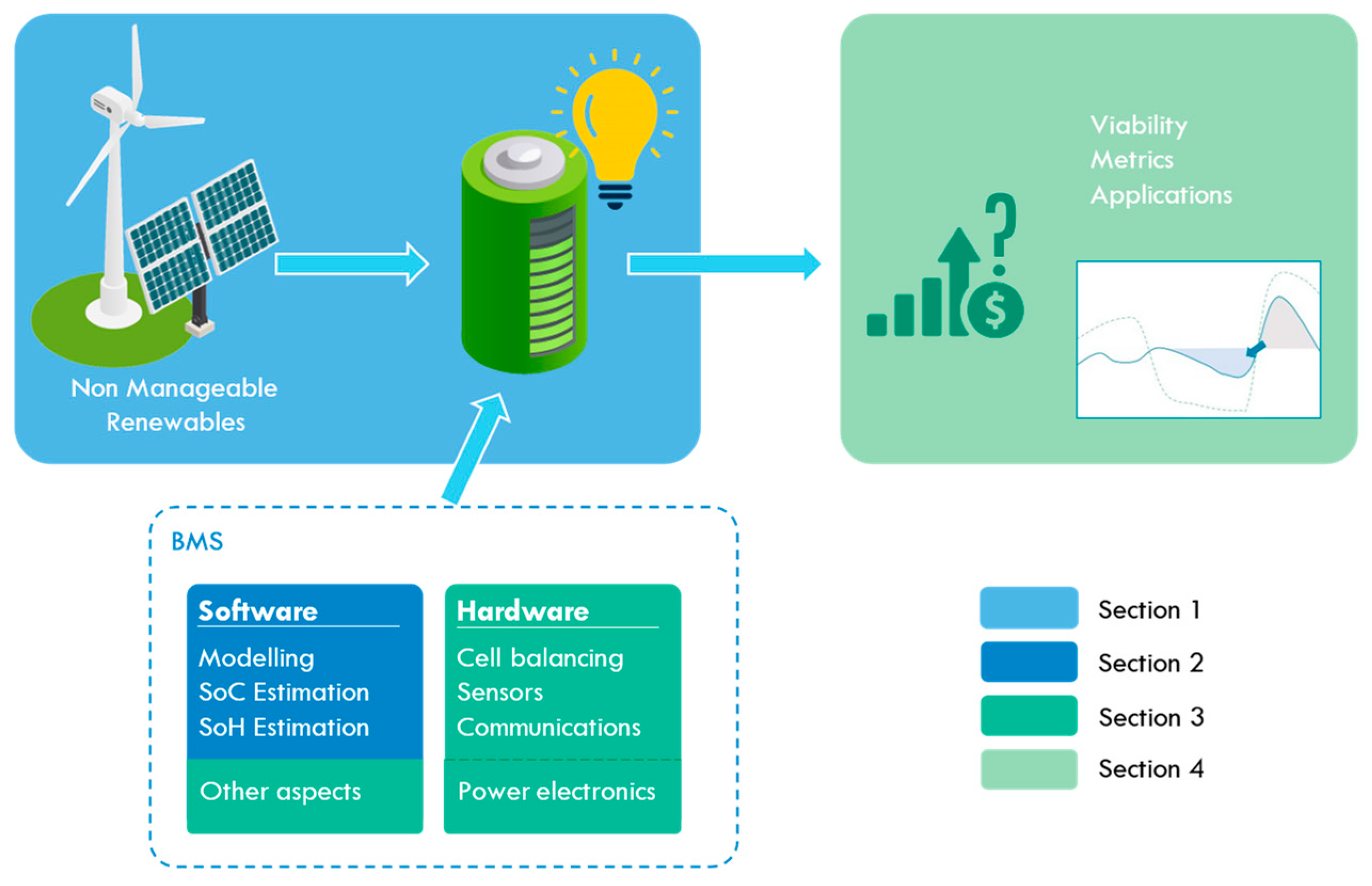


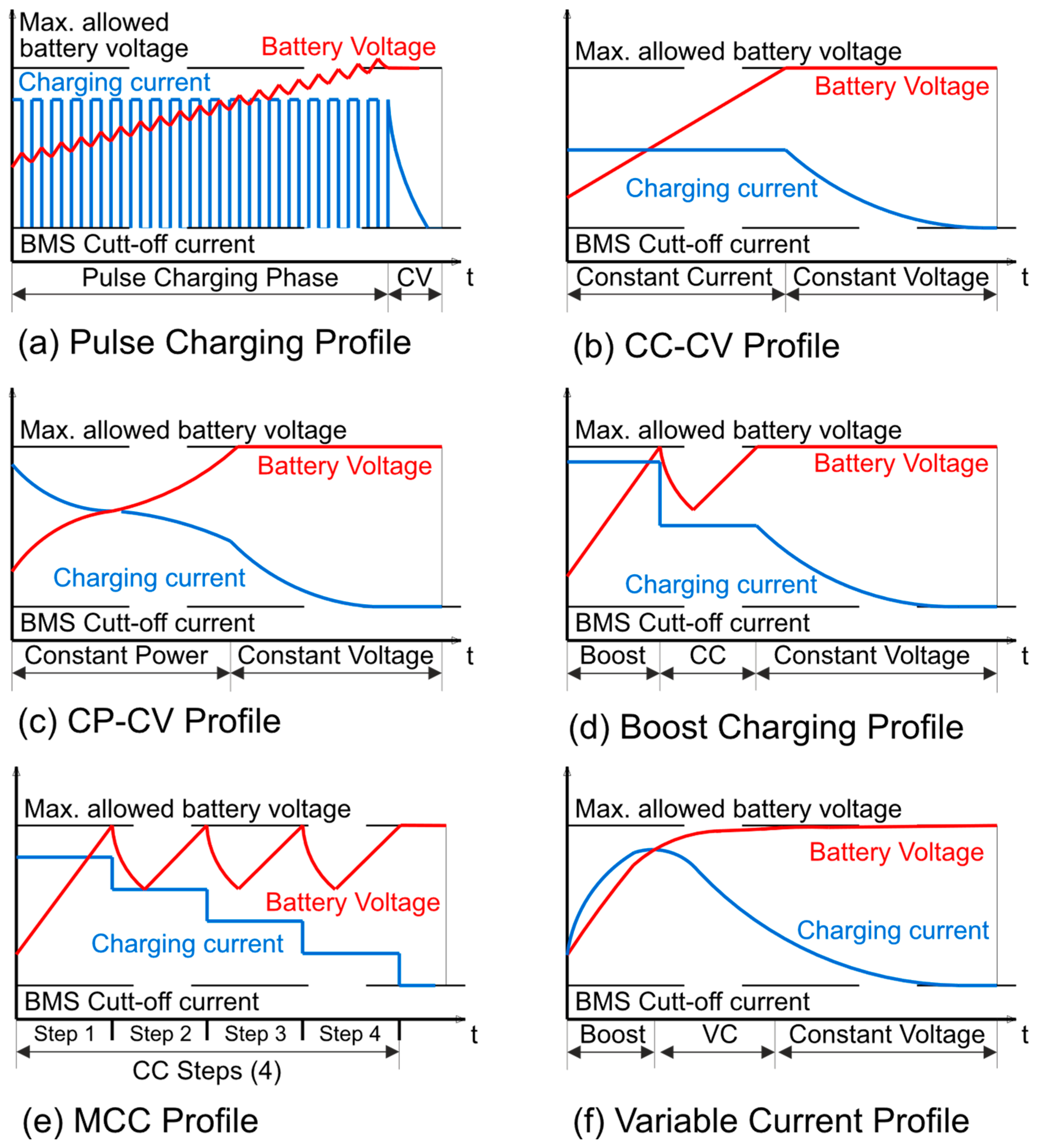
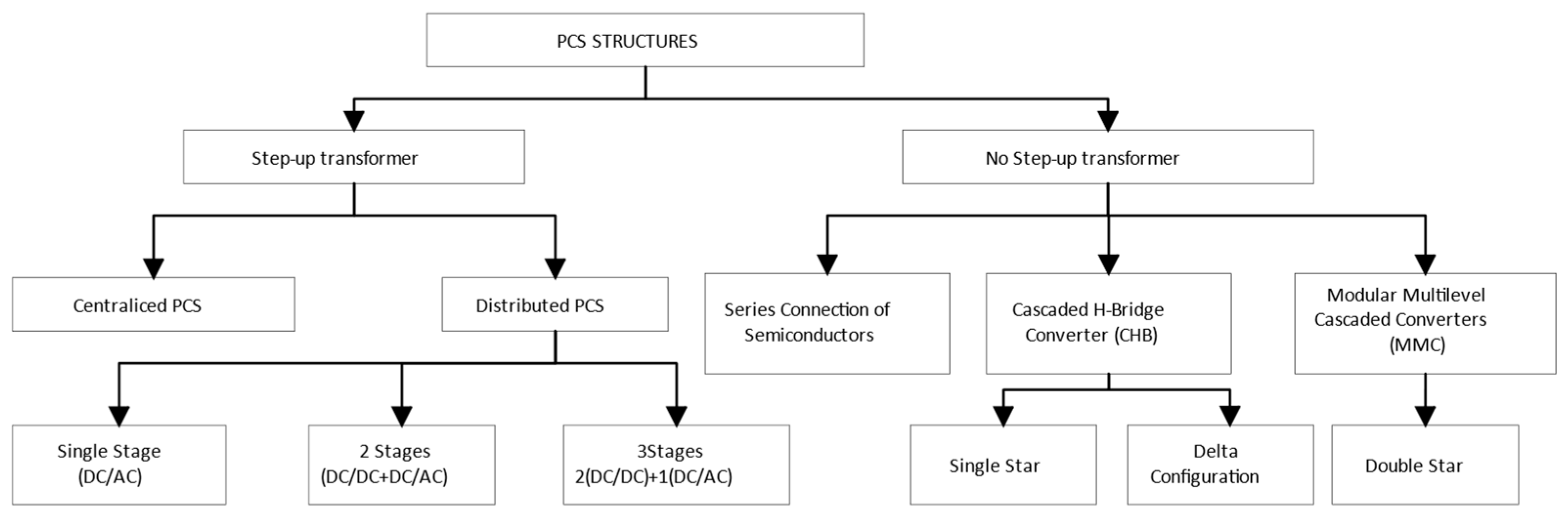


| Topic | Article | Observations |
|---|---|---|
| Battery modeling SoC, SoH, and RUL estimation | Ren and Du (2023) [13] | ML for SoC and SoH. LIBs for EVs. |
| Zhang et al. (2023) [14] | Data-driven SoH of LIBs. Accurate and sufficient datasets are crucial for appropriate predictions. | |
| Shao et al. (2023) [15] | RUL prediction methods, LIBs. | |
| Ghalkhani and Habibi (2023) [16] | AI and ML for more accurate prediction of SoC, SoH, etc. Focus on EVs. Also on battery design, thermal management. | |
| Ul Hassan et al. (2022) [17] | SoC estimation techniques for batteries in power grids, including a detailed description of each and highlighting their pros and cons in power grid applications. Reliability in estimation crucial to maximize renewable energy sources utilization and to support the grid. | |
| Luo et al. (2022) [18] | Deep learning for SoH, SoC, and RUL prediction for LIBs. | |
| Hossain Lipu et al. (2022) [19] | Deep learning for SoH, SoC, and RUL prediction for EVs. | |
| Ansari et al. (2022) [20] | RUL prediction methods for LIBs. Identification of issues and challenges in RUL prediction and research gaps. | |
| Wang et al. (2022) [21] | Battery state prediction. Accurate models are key for ensuring reliability and optimized operation. Data-driven methods based on AI have large potential. | |
| Rouholamini et al. (2022) [22] | In one of its sections, this article covers battery modeling. | |
| Puleston et al. (2022) [23] | Comprehensive study of dynamic models for VRFB available in the literature, together with an analysis of the existing model-based estimation strategies. | |
| Cui et al. (2022) [24] | SoC definition, SoC estimation of LIBs using neural network methods, methods classification, error metrics evaluation for different approaches, and makes recommendations for next-generation BMSs. | |
| Jiang and Song (2022) [25] | SoH estimation methods for lead–acid batteries. | |
| Chan et al. (2022) [26] | Electrochemical impedance spectroscopy SoH estimation for LIBs. | |
| Peng et al. (2022) [27] | Capacity estimation methods for BMSs in EVs and RESs and provides practical and feasible advice for capacity estimation with onboard BMSs. | |
| Wang et al. (2021) [28] | Deep-learning for RUL prediction for LIBs. | |
| Espedal et al. (2021) [29] | SoC estimation for LIBs in EVs. | |
| Basia et al. (2021) [30] | SoH estimation techniques and presents a novel feature-based classification. | |
| How et al. (2019) [31] | SoC estimation methods highlighting the model-based and data-driven approaches. | |
| Meng et al. (2018) [32] | Battery modeling methods with potential to be used in a model-based SoC estimation structure. | |
| Madani et al. (2018) [33] | Equivalent circuit models and parameters identification methods in lithium-ion batteries for energy storage applications. | |
| BMS | Liu et al. (2023) [34] | Conventional battery management, challenges, and data-driven approach. |
| See et al. (2022) [35] | BMS integration; recommendations for safety design and performance optimization. | |
| Krishna et al. (2022) [36] | Traditional BMSs have limitations, and digitalization to improve BESS performance. | |
| Tran et al. (2022) [37] | Cloud-based BMS for LIBs. Traditional BMS limited by low computational capacity and data storage; solved by cloud capabilities. | |
| Gabbar et al. (2021) [38] | BMS and standardization for transportation and stationary. Recommendations for BMS development based on several aspects. |
| Reference | Technology | Model Type | Observations |
|---|---|---|---|
| Salameh et al. (1992) [59] | Lead–acid | Thevenin model modified | Substitutes voltage source for a capacitor. One RC pair used. Different resistors used in charge and discharge. Self-discharge considered. Temperature compensation for self-discharge resistor. Battery pack model. No error metrics provided. |
| Ceraolo (2000) [46] | Lead–acid | Thevenin model with self-discharge | Two RC pairs used. Thermal effects modelled. Self-discharge considered. Battery model. No error metrics provided. |
| Chen et al. (2006) [47] | Lead–acid, NiCd, NiMH, Li-ion, polymer Li-ion, and others | Thevenin model modified | Two RC pairs used. Voltage source on circuit modeling capacity for OCV. Battery capacity depends on cycle number and temperature. Self-discharge considered. Value of resistor dependent on cycles, SoC, and temperature. Battery model. Max voltage error 30 mV; max runtime error 0.395%. |
| Ng et al. (2008) [60] | Lead–acid | Thevenin model | One RC pair used. OCV values dependent on SoC and current rate. Battery model. No error metrics provided. Focus on SoC estimation. |
| Peng, (2011) [42] | Lead–acid | Thevenin model | One RC pair used. Thermal effects modelled. LUT parameters’ dependence with SoC and temperature. Max. error 1.49% for dynamic current profile. Battery pack model. |
| Roselyn et al. (2021) [44] | Lead–acid | Shepherd model | Separate branches for charge and discharge. Hysteresis considered in SoC estimation, not in terminal voltage. Battery pack model. No error metrics provided. Focus on SoC estimation. |
| Lavety et al. (2021) [61] | Lead–acid | Thevenin model | One RC pair used. Model of battery cell. Only discharge is modelled. Battery pack model. Max. error 0.4% for step increasing/decreasing load. |
| Yi-Feng et al. (2021) [62] | Sodium-ion | Thevenin model | Multiple RC pairs tested. From 0 to 3. Focuses only on discharge. Fitting of parameter dependency with SoC with polynomials. Bayesian information criteria used to set polynomial order. Battery model. RMSE error 5.5 mV for three-order model. |
| Rabab et al. (2022) [63] | Sodium-ion | Thevenin-model-based | Interesting insights about operating areas of sodium-ion batteries. Parameters estimation from physics equations. One RC pair used. Dependence of parameters with temperature. Battery model. Relative error at high SoC 4.2% and 20.72% for low SoC. |
| Norian (2011) [64] | Nickel–cadmium | Thevenin model | One RC pair used. Parameters dependence of SoC. Battery model. No error metrics provided. Focus on parameter identification. |
| García-Plaza et al. (2015) [65] | Nickel–cadmium | Thevenin-model-based | Two RC pairs used. Three circuits used to model battery cell: hysteresis, Ah counting, and voltage current. Self-discharge considered. Dependency of parameters with SoC. Battery pack model extrapolation from battery model. Average cell model error 0.34% and stack model error 0.44%. |
| Micea et al. (2011) [66] | Ni-MH | Thevenin model | One RC pair. OCV–SoC relationship updated online. Battery model. No error metrics provided. Focus on remaining cycles estimation. |
| Xuyun et Zechang (2008) [67] | Ni-MH | Impedance-based | One RC pair considered and a Warburg impedance. Hysteresis considered in open-circuit voltage. Battery pack model. No error metrics provided, only graphics. |
| Yin-Zhu (2016) [68] | Ni-MH | Impedance-based | Modified Randles circuit with an additional ZC pair. Constant phase impedance element used to model non-ideal mechanisms. Offers interpretation of electrochemical phenomena with circuit elements. Insights about behavior change with aging. |
| Buller et al. (2003) [69] | Li-ion, supercapacitors | Impedance-based | Zarc and Warburg elements modelled as multiple RC pairs. Charge transfer resistance modelled with Butler–Volmer equation. OCV–SoC dependency stored in LUT. No error metrics provided, only graphics. |
| Erdinc et al. (2009) [70] | Li-ion (not specified) | Thevenin model modified | Parameters dependent on SoC, equations. Capacity update considering cycle and calendar losses. Effects of temperature considered. Series resistance with dependency on cycles elapsed. Battery model. No error metrics provided, only graphics. |
| Xiong et al. (2011) [71] | LiFePo4 | Thevenin model | OCV–SoC relationship from Nernst equation. One RC pair used. Battery model. Max. error less than 1% for Dynamic Stress Test current profile. |
| Karsten Propp et al. (2016) [72] | Li-S | Thevenin model modified | Behavioral modification of Thevenin model. Temperature effects considered. Polynomial functions for parameter dependency with temperature. Parameters dependency with SoC. Self-discharge not considered. RMSE 0.32 mV for New European Driving Cycle current profile. |
| Jiang et al. (2017) [73] | Li-S | Thevenin model | One RC pair used. Insights about Li-S internal mechanisms and model deviations. Battery model. Error 3% in most SoC regions, excluding lower SoC values. |
| Cleary et al. (2022) [56] | Solid State Li-S | Thevenin model | Multiple RC pairs studied. Series resistance dependency with SoC. Linear interpolation to model OCV and series resistance dependency with SoC. Battery model. RMS error range depending on model complexity. 9.498–18.730 mV using current profile similar to the Hybrid Pulse Power Characterization Test. |
| Baccouche et al. (2022) [74] | Li-NMC | Thevenin Model | One and two RC pairs used. Parameters dependency with SoC and Crate. Different parameters used for charge and discharge. Temperature effects not considered. (Constant at 25 °C). Battery model. Error less than 1% for SoC range of 10–100% using Dynamic Discharge Pulse current profile. |
| Sadhukhan et al. (2022) [75] | LiFePo4 | Thevenin model | Two RC pairs used. Parameters dependent on SoC. OCV–SoC fitted with polynomial equation. Battery model. No error metrics provided. Focus on SoC estimation. |
| Karimi et al. (2023) [76] | Li-C | Thevenin model | Two RC pairs used. Temperature effects considered (−30 °C, 60 °C). LUTs for model parameters, for charge and for discharge. Battery model. Max. error 3% using dynamic current profile. |
| Zhang et al. (2015) [77] | VRFB | Thevenin model modified | First-order Randles circuit. Vanadium diffusion and shunt current modelled. OCV modelled with simplified Nernst equation. Temperature effects not considered. Internal series resistance dependent on SoC. LUT for parameter values, flow rates, and current densities. Hydraulic model and pump considered. Mean error 0.09 V using dynamic current step profile. |
| Mohamed et al. (2013) [78] | VRFB | Thevenin model | Two RC pairs used. Diffusion and shunt currents not considered. Temperature, current density, flow rate, and concentrations not considered. Extended Kalman Filter for online parameter estimation. Mean error 4.9 mV during charge–discharge cycle. |
| Xiong et al. (2019) [79] | VRFB | Thevenin model modified | Coupled electro-thermal model. Diffusion and shunt currents modelled through resistors. Two RC pairs used. Temperature effects considered. OCV modelled with Nernst equation. Max. error 15 mV per cell using wind generation current profile. |
| Khaki et al. (2021) [80] | VRFB | Thevenin model with electro-chemical model | Complex dynamic model used to determine OCV. Thevenin model with one RC pair. Adaptative Kalman Filters for parameter estimation. Mean error 0.88% for ECM-Hybrid Extended Kalman Filter and 0.79% for ECM-Particle Filete using Constant Current—Constant Voltage charge profile. |
| Woodfield et al. (2022) [81] | VRFB | Thevenin model modified | Same model used as Zhang et al., 2015 [77] but includes comprehensive shunt current resistors network. Includes thermal and hydraulic model. No error metrics provided; purely a simulation article. |
| Reference | Technology | SoC Algorithm | Observations |
|---|---|---|---|
| Santhanapoongodi et al. (2016) [92] | Lead–acid | Terminal voltage-SoC LUT | 12 V, 45 Ah battery pack tested. Different current rates considered. |
| Santos et al. (2017) [93] | Lead–acid | EKF | Effects of temperature considered. ECM is a second-order Thevenin model. Parameter estimation using MATLAB curve fitting toolbox. Linear interpolation SoC–OCV. 100 Ah battery pack tested. |
| Roselyn et al. (2021) [44] | Lead–acid | Coulomb counting with hysteresis correction | 12 V, 62 Ah battery pack tested. Shepherd model used for battery. Genetic algorithm for parameter identification. Coulomb counting error reduced from 14.14% to 1.27%. |
| Sun et al. (2022) [94] | Lead–acid | Online sequence ELM | Adaboost for network training. SoC estimated from electrolyte density. Online incremental learning. RMSE 0.018–0.03 g/cm3. |
| Tiwari et al. (2018) [95] | Sodium-ion | CFFN (Three layers) | Fabricated battery Na0.7Ni0.3Mn0.59Co0.1Cu0.01O2 tested. Backpropagation for network training. Two current rates considered. Three temperatures considered. RMSE 0.94%. |
| Darbar et al. (2022) [96] | Sodium-ion | FFN (Two layers) | Na0.67Fe0.5Mn0.5O2 (NFM) as a cathode and Na metal as a reference electrode battery tested. Network trained for different current rates and cycles. RMSE 1.22–2.23%. |
| Verbrugge et al. (2004) [97] | Ni-MH | Coulomb counting filtered | 12.5 Ah battery tested. Thevenin model with one RC pair. OCV modelled by Nernst equation. Parameter estimation using least square regression. Considers self-discharge. Hysteresis considered. SoC calculation from Coulomb counting SoC. SoC obtained from model OCV. |
| Windarko et al. (2010) [98] | Ni-MH | OCV | Sebang GMH 100 NiMH Battery rated at 1.2 V and 100 Ah. Rint model with different resistors for charge and discharge. Values dependent on SoC. Takacs hysteresis model to improve OCV–SoC relationship. Maximum error of 10%. |
| Xing et al. (2014) [99] | Li-ion | UKF | LiFePO4 18650 cylindrical type battery tested. Rint model; resistor value dependent on temperature. OCV–SoC–temperature LUT. Parameter fitting using least square regression. RMSE 1.1–24.63%. |
| Cheng et al. (2014) [100] | Li-ion | Finite difference EKF | Lithium iron phosphate LP2770102AC battery. Second-order Randles circuit. Parameter identification using non-linear least squares. RMSE of 1.74%. |
| Chung and Yang (2018) [101] | Li-ion | EKF | First-order Randles circuit; OCV modelled as capacitor. Parameters depend on SoC, temperature, and current rates. Average error 0.15%. |
| Fang et al. (2021) [102] | Li-ion | Fractional order UKF | Panasonic NCR18650B, 3.4 Ah, 3.7 V battery tested. Model with two RC pairs. State space equation with fractional order. Adaptive genetic algorithm for parameter identification. RMSE 0.7–1.0%. |
| Huang et al. (2021) [103] | Li-ion | EKF | Lithium iron phosphate 20 Ah battery pack tested. Online parameter identification with recursive least squares with forgetting factor. Levenberg–Marquardt modification of covariance matrix. RMS error 1.216%. |
| Berrueta et al. (2021) [104] | Li-ion | EKF simplified | Second life 66 Ah battery pack tested. First-order Randles circuit. Model with constant parameters. Comparison with Ampere Counting, Adaptive PF, and MATLAB’s EKF. RMSE 4.2–6.0%. |
| Zhang et al. (2022) [85] | Li-ion | RNN + UKF | Samsung INR 18650-20R and INR 18650-25R under various ambient temperatures; (CALCE) battery dataset. UKF refines output of RNN. Effects of temperature considered. RMSE error 1.5–3.4%. |
| Chen et al. (2023) [83] | Li-ion | EKF | 2.6 Ah, 4.2 V battery tested. Parameter estimation by genetic algorithm and Levenberg–Marquardt algorithm. Second-order Randles model. MAE 0.3%. |
| Zheng et al. (2018) [105] | VRFB | Dual KF (EKF + KF) | 5 kW/30 kWh energy storage system tested. ECM: Shunt current source modeling pump consumption. Shunt resistance modeling parasitic reactions. Series resistor. Real voltage source with parallel capacitor. KF receives output of Coulomb counting and EKF and estimates SoC. Error 1.5%. |
| Clemente et al. (2021) [87] | VRFB | SMO | Single-cell VRFB tested. Simplified physics model; electrolyte tanks balanced and equal flows. Particle Swarm for parameter identification. |
| Khaki et al. (2021) [89] | VRFB | OCV | Nine-cell VRFB prototype tested. Two models proposed: Dynamic electrochemical model. ECM (first-order Randles). SoC computed from OCV using adapted Nernst equation. RMSE error—11.19%. |
| Reference | Technology | Estimation Algorithm | Observations |
|---|---|---|---|
| Shahriari and Farrokhi (2013) [107] | Lead–acid | EKF + Radial Basis Function NN | 6 batteries used with different aging. 3 for training, 3 for testing. NN used for battery pack modeling and EKF for SoC estimation. Activation function of NN of Gaussian type. Online SoH estimation from charge–OCV slope, estimating the slope using recursive least squares. Constant temperature. Maximum error 3.0%. |
| Chaoui et al. (2015) [115] | Lead–acid | Parameter-model-based | . Genetic algorithm for parameter estimation. . Linear correction of temperature with manufacturer coefficient. |
| Sadabadi et al. (2021) [109] | Lead–acid Starting–lighting–ignition | Parameter-model-based | Three aged battery packs tested. Second-order Randles ECM. R series value obtained from instant voltage drop. RC values from Nelder–Mead optimization. Explores evolution of ECM parameters with aging. Used a map between RC resistors, SoC and SoH. SoH estimation error 0.8–12.2%. |
| Haifeng et al. (2009) [114] | Li-ion | DEKF | SoH definition based on ohmic resistance value. Dual Extended Kalman Filter for ohmic resistance estimation. |
| Andre et al. (2013) [121] | Li-ion | DEKF + SVR | High-energy lithium-ion pouch cells with a graphite anode and a NMC cathode. Cells with nominal voltage 3.6 V and nominal capacity 10 Ah. Tested over four cells. Second-order Randles circuit. DEFK for SoC estimation and SVR for capacity estimation. Max error of SoH below 20.0%. |
| Fan et al. (2019) [122] | Li-ion | Parameter-model-based | Eight LiNMC battery cells with 0.94 Ah nominal capacity, 3.7 V nominal voltage tested. First-order Randles circuit. OCV–SoC–C LUT. Uses affine projection for parameter estimation. Particle swarm for capacity matching with data using OCV–SoC–C LUT. Estimates current capacity and then SoH. Relative error below 1% for all conditions and different aging states. |
| Lee and Lee, (2021) [112] | Li-ion | Multiple neural networks | Qualitative SoH estimation. Three values (normal, caution, fault). One multilayer for SoH diagnosis, and three NN model banks for SoC estimation. Each model bank comprises normal, caution, and fault model. (Capacity 100–90%, 90–80%, <80%). SoH reused for SoC estimation. Average error of 0.58%. |
| Gong et al. (2022) [123] | Li-ion | GPR, SVR, and LR | Data from MIT, CALCE, NASA, and Oxford datasets. Three energy metrics used for SoH estimation: Constant Current charge phase energy. Constant Voltage charge phase energy. Equal discharge voltage interval phase energy. Comparison of the following algorithms: Elastic net linear regression. Support Vector Regression. Gaussian Process Regression. Prediction errors 0.5%, R2 97.0%. |
| Ezemobi et al. (2022) [111] | Li-ion | FFNN | LiNiMnCoO2 Nominal capacity 3500 mAh, nominal voltage 3.635 V, cut-off voltage 2.5 V. Network comprised two hidden layers with 10 neuron each. Activation function for hidden layers: Hyperbolic tangent sigmoid. Activation function for output layer: Softmax. SoH binned in 5%. From 100% to 80%. SoH prediction accuracy of 96.2%. |
| Yang et al. (2015) [124] | Ni-MH | Non-linear regression | Commercial AA-type Ni-MH cells (Pisenr, Sichuan, China, Crated 1.8 Ah and rated voltage 1.2 V). Three charge–discharge rates. Nonlinear relationship found between the discharging capacity (Cdischarge Ah) and the voltage changes in 1 s occurring at the start of the charging process (∆Vcharge mV). Non-linear least squares method for curve fitting. The validity of the curve model verified using (Cdischarge, ∆Vcharge) data groups from the charge–discharge cycle tests at different rates. The Best (RMSE) can reach up to 1.2%. |
| Galeotti et al. (2015) [125] | Ni-MH | Impedance-based | Uses Theory of Evidence to determine number of cycles. Impedance at 2.5 Hz from EIS selected as representative frequency. Parameters for cycle estimation normalized voltage and imaginary impedance at 2.5 Hz for different SoC levels. Requires reference curves. |
| Telmoudi et al. (2020) [126] | Ni-MH | Fuzzy regression | Laboratory-made cell. Fuzzy c-regression model and Euclidean particle swarm optimization for NiMH battery. SoH determined according to the discharge rate of the battery model. Constant temperature considered. |
| Song et al. (2022) [127] | Single-Flow Zinc–Nickel | DUKF | Second-order Randles circuit. Parameter identification from constant current pulse tests SoC and ohmic resistance. RC parameters obtained by improved Harris hawk optimization (IHHO). Parameters are SoC-dependent. SoC, RC, and capacity parameters estimated with Dual Unscented Kalman Filter. IHHO used to obtain initial parameters of DUKF. |
| Clemente et al. (2023) [88] | VRFB | Parameter-model-based | Four different submodels: Electrochemical (Skyllas Kazacos), Thermal, Hydraulic, Voltage (OCV by Nernst equation considering hydrogen protons), Activation overpotential (Butler–Volmer), Ohmic overpotential (constant but different depending on whether the system is charging or discharging), Concentration overpotentials. Parameter estimation with offline estimator based on Particle Swarm optimization. SoH obtainable from model. |
| Puleston et al. (2023) [118] | VRFB | High-gain observer (HGO) + Dynamic inverter + selector | Skyllas Kazacos for concentrations and Nernst for OCV. Model reduction due to strong non-linearities. Dynamic of VRFB separated in two timescales. Correction terms to consider side reactions. Individual anolyte/catholyte SoC estimation and the reversible causes of the battery capacity fading are distinguished from the irreversible ones. Observability analysis performed. High gain observer + Dynamic inverter + Selector SoC and SoH estimation. Relative error below 2%. Mean 0.51%. |
| Objective | Area | Description | Tasks |
|---|---|---|---|
| Safety | Main directive (Monitoring and protection of batteries) | Critical functions, which take priority | Voltage monitoring |
| Temperature monitoring | |||
| Reliability | Monitoring other parameters (chemical reactions, external temperature, humidity, etc.) | ||
| Current control | |||
| Stop battery operation | |||
| Increase battery life | Secondary directives (Performance of the system) | Management of the storage medium | Cell balancing (on charge) |
| Optimize benefits | Charging cycle control | ||
| Load balance of cells (on discharge) | |||
| Increase system stability | Isolation of cells | ||
| Other | |||
| Faulty and status signals | Feedback (Communication) | Interrelation with other elements inside the ESS | Data connectivity |
| Stored energy and available output | |||
| Two-way communication with ESS and its subsystems (BTMS, etc.) |
| Technology | Temperature Range (Recommended) | Voltage Range (Cell) | Recommended Operation (Cell) | Notes |
|---|---|---|---|---|
| Lead–acid—VRLA [129] | −20 to 45 °C | 2.20 to 2.35 V 1 | 5 to 35 °C 2.25 to 2.30 V | Using the battery for prolonged periods over 40 °C causes a thermal runway. |
| Lead–acid—VLA [130] | −40 to 55 °C | 2.15 to 2.45 V 1 | Using the battery for prolonged periods over 55 °C causes a thermal runway. | |
| Nickel–cadmium (Ni-Cd) [131] | 0 °C to 45 °C (Charge) −20 °C to 65 °C (Discharge) | 0.90 to 1.50 V | 1.3 V–20 °C | Charge acceptance at 45 °C is 70%. Charge acceptance at 60 °C is 45%. |
| Nickel–metal hydride (NiMH) [132,133] | 0.90 to 1.50 V | 1.2 V–20 °C | ||
| Lithium-ion (Li-ion) [134] | 0 °C to 45 °C (Charge) –20 °C to 60 °C (Discharge) | ~2 to 4.2 V | 0–20 °C Voltage depends on chemistry | No charge permitted below freezing point. Good charge/discharge performance at higher temperature but shorter life. |
| Lithium–sulfur (LiS) [135,136] | −60 °C to +70 °C | 1.90 to 2.45 V | 2.45 V at 20 °C (Charge) 1.9 V at 20 °C (Discharge) | Storage temperature: −60 °C to 85 °C (30 °C recommended). |
| Lithium–metal–polymer (LMP) [137] | −30 °C to +65 °C | 2.5 to 4.5 V | ? | |
| Sodium-ion (Na-ion) [138,139] | −20 °C to +60 °C | 1.5 to 4.3 V | ? | |
| Sodium–sulfur (NaS) [140] | 260–350 °C | 1.78 to 2.208 V | ? | |
| Sodium–nickel–chloride (Na/NiCl2) [141] | 270 °C–350 °C | 2.67 to 3.1 V | 2.58 V (nominal voltage) | |
| Redox flow batteries [142] | ? | 1.15–1.55 V | ? | 30 °C recommended operation temperature |
| Zinc–bromine flow batteries (ZnBr-FBs) [143] | 20–50 °C | 1–1.82 V | 1.5 V (nominal at ambient temperature) |
| C-Rate | Time |
|---|---|
| 5C | 12 min |
| 2C | 30 min |
| 1C | 1 h |
| 0.5C or C/2 | 2 h |
| 0.2C or C/5 | 5 h |
| 0.1C or C/10 | 10 h |
| 0.05C or C/20 | 20 h |
| Topology | Cell Balancing | Characteristics | Failures and Isolation | ||
|---|---|---|---|---|---|
| Short Circuit | Open Circuit | Isolation * | |||
| Series | Needed per cell | Same current on cells and load Load voltage, sum of cells voltages Higher current and cell temperature | Yes | Yes | Cell—reduced capacity and voltage |
| Parallel | Natural equalization | Same voltage on cells and load Load current, sum of current in each cell | Yes | No | Cell—reduced capacity and maximum discharge current |
| SCC | Needed per cell | Stacks of cells connected in series Stacks are connected in parallel | Yes (cell) Reduced effect (stack) | Yes (cell), disables stack No (stack) | Stack—reduced capacity and maximum discharge current |
| PCC | Needed per stack (minor) | Stacks of cells connected in parallel Stacks are connected in series | Yes (reduced effect) | No (slight reduction in maximum discharge current) | Stack—reduced capacity and voltage |
| Financial Metrics | Definition | Formula | Literature Where It Is Utilized 1 |
|---|---|---|---|
| Net Present Value (NPV) | NPV measures the profitability of an investment by calculating the difference between the present value of cash inflows and outflows. | CF(t): expected cash flow year t CF0: initial investment r: discount rate. | [272,278,279,280,281,282,283,284,285,286,287,288,289,290,291,292,293,294,295,296,297,298,299,300,301,302,303,304,305,306,307] |
| Levelized Costs of Storage (LCOS) | It is a metric used in the energy sector, specifically for battery projects, representing the average cost of deploying and operating an energy storage system over its lifetime. | cost(t): Cost in year t Eout(t): Electricity discharged year t r: discount rate. | [290,308,309,310,311,312,313,314,315,316,317,318,319] |
| Levelized Costs of Energy (LCOE) | It is a measure of the average net present cost of electricity generation for a generator (in this case, generator + storage) over its lifetime. | cost(t): Cost in year t E(t): Electricity generated year t r: discount rate. | [272,284,301,302,305,306,308,310,311,312,314,318,320,321,322,323,324,325,326,327,328,329,330,331,332,333,334,335] |
| Internal Rate of Return (IRR) | IRR is the discount rate that equates the net present value of cash inflows and outflows to zero. | CFt: expected cash flow in year t CF0: initial investment r: discount rate. | [257,285,288,289,290,295,298,299,305,328,336,337,338,339,340] |
| Net Present Cost (NPC) | NPC evaluates the total cost of an investment over its entire life cycle, including initial investment and operational and maintenance costs. | t cost(t): Cost in year t r: discount rate. | [302,324,326,328,330,333,334,341,342,343] |
| Payback Period (PP) | The payback period measures the time required for the cumulative cash inflows from an investment to equal the initial investment cost. | t: Break-even year Ut: Unrecovered amount in year t CFt: expected cash flow in year t. | [238,278,279,289,295,299,300,305,306,325,338,344,345,346,347,348,349,350] |
| Discounted Payback (DPB) | Similar to payback period, discounted payback considers the time value of money by discounting the cash flows. | td: Break-even year (discounted) Utd: Unrecovered amount in year t (discounted) CFtd: expected cash flow in year t (discounted). | [238,286,289,295,298,303,328,339,344,347,348,351] |
| Equivalent Annual Cost (EAC) | EAC represents the average annual cost of an investment, considering both initial and recurring costs over its expected lifespan. | cost(t): expected cost in year t cost0: initial investment r: discount rate. | [326,329,352,353,354,355,356,357,358] |
Disclaimer/Publisher’s Note: The statements, opinions and data contained in all publications are solely those of the individual author(s) and contributor(s) and not of MDPI and/or the editor(s). MDPI and/or the editor(s) disclaim responsibility for any injury to people or property resulting from any ideas, methods, instructions or products referred to in the content. |
© 2023 by the authors. Licensee MDPI, Basel, Switzerland. This article is an open access article distributed under the terms and conditions of the Creative Commons Attribution (CC BY) license (https://creativecommons.org/licenses/by/4.0/).
Share and Cite
Carrasco Ortega, P.; Durán Gómez, P.; Mérida Sánchez, J.C.; Echevarría Camarero, F.; Pardiñas, Á.Á. Battery Energy Storage Systems for the New Electricity Market Landscape: Modeling, State Diagnostics, Management, and Viability—A Review. Energies 2023, 16, 6334. https://doi.org/10.3390/en16176334
Carrasco Ortega P, Durán Gómez P, Mérida Sánchez JC, Echevarría Camarero F, Pardiñas ÁÁ. Battery Energy Storage Systems for the New Electricity Market Landscape: Modeling, State Diagnostics, Management, and Viability—A Review. Energies. 2023; 16(17):6334. https://doi.org/10.3390/en16176334
Chicago/Turabian StyleCarrasco Ortega, Pablo, Pablo Durán Gómez, Julio César Mérida Sánchez, Fernando Echevarría Camarero, and Ángel Á. Pardiñas. 2023. "Battery Energy Storage Systems for the New Electricity Market Landscape: Modeling, State Diagnostics, Management, and Viability—A Review" Energies 16, no. 17: 6334. https://doi.org/10.3390/en16176334
APA StyleCarrasco Ortega, P., Durán Gómez, P., Mérida Sánchez, J. C., Echevarría Camarero, F., & Pardiñas, Á. Á. (2023). Battery Energy Storage Systems for the New Electricity Market Landscape: Modeling, State Diagnostics, Management, and Viability—A Review. Energies, 16(17), 6334. https://doi.org/10.3390/en16176334