Article

A Study on Various Conditions Impacting the Harmonics at Point of Common Coupling in On-Grid Solar Photovoltaic Systems

by
Talada Appala Naidu
*,
Hamad Mohamed Ali Ahmed Albeshr
,
Ammar Al-Sabounchi
,
Sajan K. Sadanandan
and
Tareg Ghaoud
Dubai Electricity and Water Authority (DEWA), Dubai P.O. Box 564, United Arab Emirates
*
Author to whom correspondence should be addressed.
Energies 2023, 16(17), 6398; https://doi.org/10.3390/en16176398
Submission received: 19 June 2023 / Revised: 3 August 2023 / Accepted: 5 August 2023 / Published: 4 September 2023

Abstract

:
Renewable penetration, particularly the increasing deployment of PV by residential customers, organizations, and utilities, is leading to the rapid evolution of the power grid. However, the power system’s architectural changes affect the quality of supply and give rise to power quality issues such as harmonics, fluctuations, disturbances, etc., at the point of common coupling (PCC). Therefore, in this work, a power network was modeled to study the impact of PV systems on PCC. At first, a detailed review is presented for on-grid PV systems with different inverter topologies, control techniques, sources of harmonic generation, and their mitigation strategies. After that, several use cases considering various sources of harmonics in a network with on-grid PV are modeled and simulated using MATLAB/Simulink. In-depth research was performed in this work to examine the many variables that affect harmonics, such as solar radiation levels, controller tuning, and load changes. Results with a real-time simulation platform (OPAL-RT) are presented in this paper for several use cases. Lastly, comprehensive discussions are presented from the acquired offline and real-time simulation results.

1. Introduction

Solar photovoltaic (PV) demand is growing, as it has become the most cost-effective alternative for energy production in many areas, such as residential and commercial applications, utility-scale projects, etc. According to the Renewables global status report, all continents contributed substantially to the worldwide growth in the total capacity of renewables. Figure 1 depicts the global solar PV capacity and annual addition from 2010 to 2023 [1], which shows a 350 GW addition is projected in the year 2023 globally [2].
The fundamental goals of a power system are to create high-quality energy, transfer it efficiently, and provide it to customers for a reasonable price. The utility system must deliver energy to all consumers at the rated voltage magnitude and frequency [3]. Simultaneously protecting the environment from the danger of gas emissions and decreasing the risk of global warming, the adoption of renewable energy technology has grown rapidly [4]. Also, it is essential for utilities to accomplish their primary objective, which is to transfer electricity as efficiently as possible from the generation plant to the end users [5]. To achieve the above requirements, PV technology has shown the highest potential for environmental friendliness, security, and effectiveness [6]. As a result, a high increase in PV penetration into the grid has been observed over the years [7]. PV systems with a suitable topology and filter configuration are generally connected to the grid using an inverter (DC/AC) at the point of common coupling (PCC). Because of the increased penetration of PV on the grid, the traditional power quality definitions that were previously valid mainly for balanced and pure sinusoidal waveforms will not be accurate in representing the current power systems with large PV installations. Therefore, power system conditions like unbalanced loads, non-sinusoidal voltage, and current waveforms have drawn much interest in the last few years [8].
The inverter-based PV systems inject harmonics into the grid [9]. The inverters individually might pass the rated harmonic in the test conditions because they comply with the demands of the most recent advancements in PV-inverter technology. However, when PV inverters are connected to the actual network, they might inject more harmonics and fail to maintain the harmonic limits at PCC [10]. For example, the results of a PV-based power-generating system model in [11] show that low irradiance results in low output power, low fundamental current, and high total harmonic distortion (THD); specifically, current THD is more than voltage THD. The inverter type, filters, control method, solar radiation, and temperature all impact the harmonic emissions at PCC. Moreover, combining PV inverters with highly non-linear loads might result in unwanted harmonic content at PCC [12,13]. Utility companies and customers face problems due to these higher harmonic distortions affecting their equipment, leading to capital losses. Even though individual PV systems and loads follow the limits of power quality standards from IEEE or IEC, the combined results of all separate PV systems and different loads at PCC adversely affect utility assets [14].
Therefore, in this paper, the authors investigated the different sources of harmonics in on-grid PV systems, the effects of harmonics on the grid, and mitigation methods. This was achieved by conducting a detailed literature review and simulating a number of use cases to demonstrate and show the effect of different harmonic sources on the PCC. The use cases were tested with a real-time simulator for analysis and validation. The contributions of this paper can be summarized as follows:
A detailed literature review on on-grid PV systems is presented, considering the essential components of PV systems and their functions. Further, we discuss the different PV-inverter topologies, control and modulation techniques, and potential causes of harmonics, including their mitigation strategies;
An on-grid PV system was modeled using MATLAB/Simulink to demonstrate some use cases. The use-cases examined through this simulation can be summarized as follows:
Impact of variable climatic conditions (temperature, T; irradiance, G) on the on-grid PV systems with constant load,
Impact of variable loads on the on-grid PV systems at constant climatic conditions,
Impact of harmonics with different loading levels of non-linear loads;
Furthermore, simulations were conducted using our real-time digital simulator (OPAL-RT) to validate the results. The use cases for this study are as follows:
The effect of different loads (linear, non-linear, and arc-furnace) on THD at PCC,
The effect of change in climatic conditions (irradiance, G) on THD at PCC,
The effect of change in tuning parameters such as proportional gain (kp) and integral gain (ki) of the inverter controller on THD at PCC.
The outcomes of this study are herein summarized, and the results are presented.
The remaining part of the paper is organized as follows: Section 2 describes the (a) components of on-grid PV systems and a comparison of different PV-inverter types; (b) on-grid PV systems topology, control techniques, and the features of these control techniques in on-grid PV systems; and (c) the sources of harmonic generation and their mitigation strategies. Section 3 presents the simulation study and discusses simulation results on the defined use cases. Finally, Section 4 summarizes the literature review’s conclusions and the use cases’ results.

2. On-Grid PV System

Figure 2a represents the basic configuration of grid-connected PV systems, which comprises different components like the power grid, transformer (T/F), filter, DC–AC converter, solar PV array/plant, and control circuit. A separate filter might not be necessary if the transformer winding inductance acts as a filter to deliver high-quality power exchange. However, transformers might be eliminated in low-voltage (LV) networks to reduce space, cost, and size. In such cases, a filter circuit should be between the converter and grid, as shown in the Figure, to eliminate the harmonics. The on-grid PV systems are generally connected to the grid using the following subsystems:

2.1. Components of On-Grid PV System

2.1.1. Filter Circuit

The purpose of the filter circuit is to eliminate/remove the harmonic voltage/currents generated by the converter. These filters use basic electrical parameters such as inductor (L) and capacitor (C). Based on the converter characteristics (switching frequency, voltage, current, power ratings, etc.), filter circuits can be designed using different combinations of L and C.

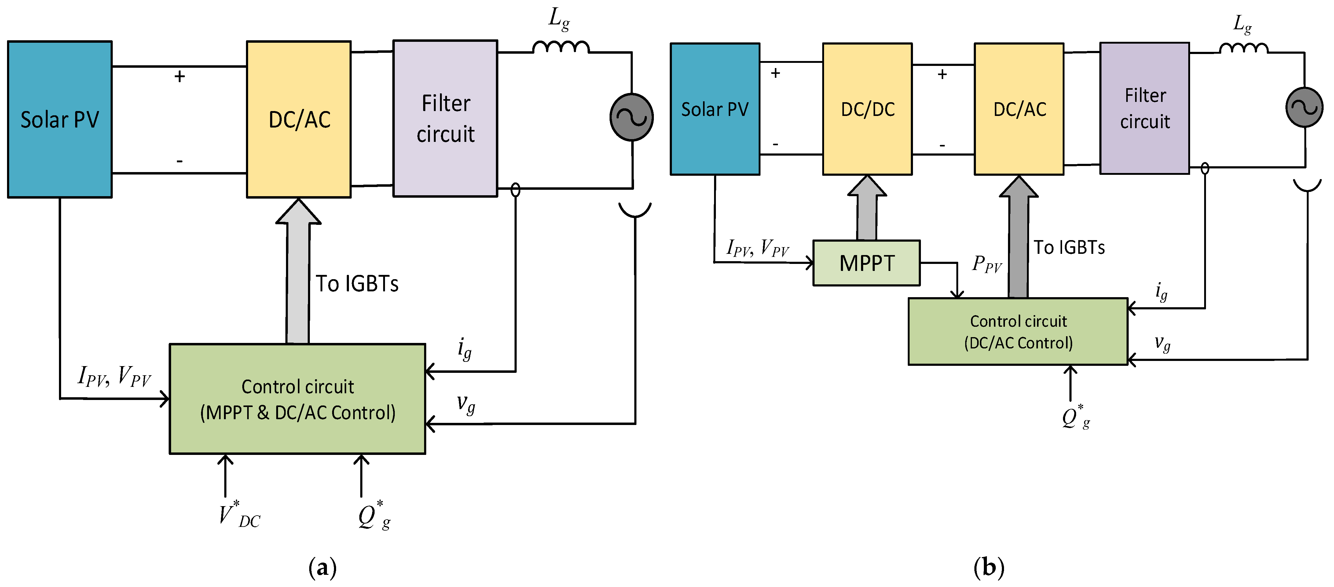
2.1.2. PV Inverters and Their Types

In an on-grid PV system, the inverters play a significant role. They convert DC power to AC power (inverter mode) and AC power to DC power (rectifier/converter mode) while exchanging power in both directions. The PV inverter uses insulated gate bipolar transistor (IGBT) with an anti-parallel diode, as shown in Figure 2b. IGBT with an anti-parallel diode works as a switch that enables protection for the IGBT by allowing the over current to pass through it when the switch is turned off. For rooftop applications, four types of PV inverters are mainly available [15]. A comparison is presented in Table 1 to discuss the advantages and disadvantages of different PV-inverter types.

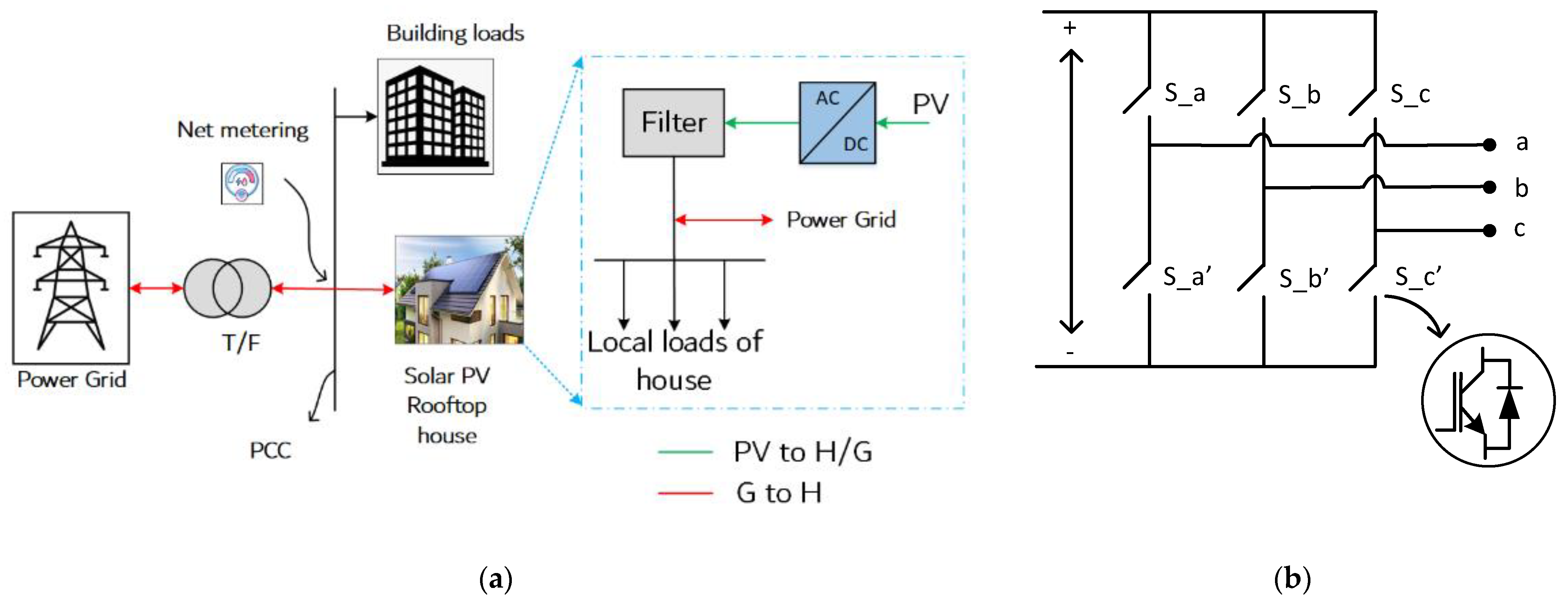
2.1.3. Solar PV Array and Net Meter

Generally, in on-grid PV applications, the PV inverter’s DC side is equipped with a solar PV array with/without DC/DC boost converter. A solar PV array is a system that consists of a collection of PV panels/modules that are joined together. The PV array will produce the desired output by connecting multiple single PV panels in series for high voltage requirements or parallel for high current requirements [17].
On the other hand, one of the main components of the on-gird PV systems is net metering. This is a unique billing mechanism known as “net metering” or “Net Energy Metering” (NEM), which gives customers who produce renewable energy credit for the value of the renewable electricity supplied by the customer to the grid. A smart meter is typically used for tracking the power consumed in hourly or sub-hourly periods. The smart meter data are then digitally transmitted to the utility, which will be used for the billing of the net energy consumed by the customer.

2.2. Topologies, Control, and Modulation Strategies in On-Grid PV Systems

2.2.1. On-Grid PV System Topologies

Grid-connected PV system topology mainly depends on the number of stages needed for converting the power from PV to the grid. For example, as shown in Figure 3, there exists single-stage conversion (DC–AC) and two-stage conversion (first DC–DC and then DC–AC) [18]. Single-stage conversion PV inverters, shown in Figure 3a, often have a narrow input DC voltage range and low power capacity due to the single stage of power conversion. In addition, when the power generation grows, the current flowing through the switching devices increases, which may damage the switches. To overcome this limitation, a line frequency transformer can be added. However, the line frequency transformer would add considerable weight to the system and would contribute to a minimum of 2% losses in the system [19]. Another option is to consider inverters with high-frequency transformers or transformer-less inverters that are more efficient and lighter than those with the low-frequency transformers mentioned above. In two-stage conversion system topologies, a DC–DC converter can be introduced, such as a buck-boost or boost converter, as shown in Figure 3b. In the two-stage conversion topology, the last stage performs DC to AC conversion, while the first stage delivers the DC–DC voltage amplification.
The literature also provides another categorization of inverters based on using low- and high-frequency transformers. Inverters employing low-frequency transformers provide electrical isolation between the PV panel and the utility grid, as shown in Figure 4a. For this reason, the line frequency transformer in this topology can also be called an isolation transformer. The isolation transformer eliminates DC injection into the power system. However, line frequency transformers are generally large and bulky, which raises the entire cost of a PV system. Another topology also exists that uses high-frequency transformers after the inverter, as shown in Figure 4b. This topology minimizes the system’s size and weight compared to one that uses the low-frequency transformer. This topology, however, requires an extra AC-to-AC converter, making it more complex to control for on-grid PV systems [20].

2.2.2. Control Strategies for On-Grid PV Inverters

Several research studies have been reported concerning power quality issues due to the high penetration of PV inverters in the distribution systems [21,22,23,24,25,26,27]. Most PV systems deliver the generated power to the grid using an inverter. Typical block diagrams that show the control circuit for an on-grid PV system include maximum power point tracking (MPPT) and inverter control, as shown in Figure 5.
Figure 5a,b represents the single-stage and two-stage PV-inverter topology control blocks, respectively. The line inductance (Lg) represents the leakage inductance of the transformer through which the inverter is connected to the grid. As the line resistance has a low impact on the system performance and is negligibly small, it can be omitted for analysis. The control of the PV inverter varies based on the stages of conversions, i.e., single-stage (DC–AC) and two-stage conversion (DC–DC and DC–AC). It is to be noted that the MPPT maintains the maximum possible power generated from the PV at all times. In two-stage conversion topologies, a boost converter modifies the output voltage of the PV to a level that the inverter input requires. In single-stage conversion topology, the inverter is modulated by a pulse width modulation (PWM) scheme.
In general, the inverter acts as a boost converter by its nature, and the average DC voltage (VDC) of the inverter can be derived from Equation (1).
V D C = 6 × V a 1 m a
where Va1 is the RMS value of the fundamental component of inverter phase voltage (va1), and ma is the modulation index. For on-grid PV systems, the power flow between the inverter and grid is unidirectional (i.e., the power is delivered from the inverter to the grid). Controlling inverters in on-grid PV systems can be achieved using various methods [28]. Different types of controllers and modulation strategies are reviewed in the following subsection.

2.2.3. Types of Control and Modulation Strategies for On-Grid PV-Inverters

Practically, the functioning of an on-grid PV system depends on the control of PV inverters. The power system must have smooth control and the reliable functioning of an inverter. If an inverter is not equipped with a reliable and appropriate controller, grid instability and disruptions can occur. In this context, in the literature, a few controllers and modulation strategies are classified listed as follows:
  • Linear controllers:
    • Phase-locked loop (PLL)-based classical controllers,
    • Proportional resonant (PR) controllers,
    • Linear quadratic Gaussian (LQG) controllers;
  • Non-linear controllers:
    • Sliding mode controllers (SMC),
    • Partial or full feedback linearization controllers,
    • Hysteresis controllers;
  • Predictive controllers:
    • Model predictive controllers (MPC),
    • Deadbeat controllers (DBC);
  • Adaptive controllers;
  • Intelligent controllers:
    • Neural network controllers (NNC),
    • Repetitive controllers (RC),
    • Fuzzy logic controllers (FLC).
In article [29], a comprehensive study of these controllers and their subclasses is presented. Table 2 describes the control features in the grid-connected PV systems.
In another study, a new approach was proposed by combining the two/three distinct controllers, such as a merge of DBC, classical, and RC controllers [29]. This approach could be used to control the on-grid PV inverter for improved functionality when integrated into the grid. Alternatively, a combination of adaptive and intelligent controllers can also be deployed for improved grid operation [39,40].

2.3. Sources of Harmonics Generation and Their Mitigation Strategies in On-Grid PV Systems

This section highlights the sources of harmonics generation in the PV inverter and their mitigation strategies. The conversion system commonly employed in the on-grid PV system is an inverter to feed the grid from its input DC source. Due to the inherent nature of an inverter, it generates undesirable voltage and current harmonics that are fed to the grid. The following subsections give detailed insight into different sources of harmonics generation in on-grid PV systems and their mitigation strategies.

2.3.1. Sources of Harmonics Generation in On-Grid PV Systems

The following factors contribute to the generation of voltage/current harmonics by PV inverters:
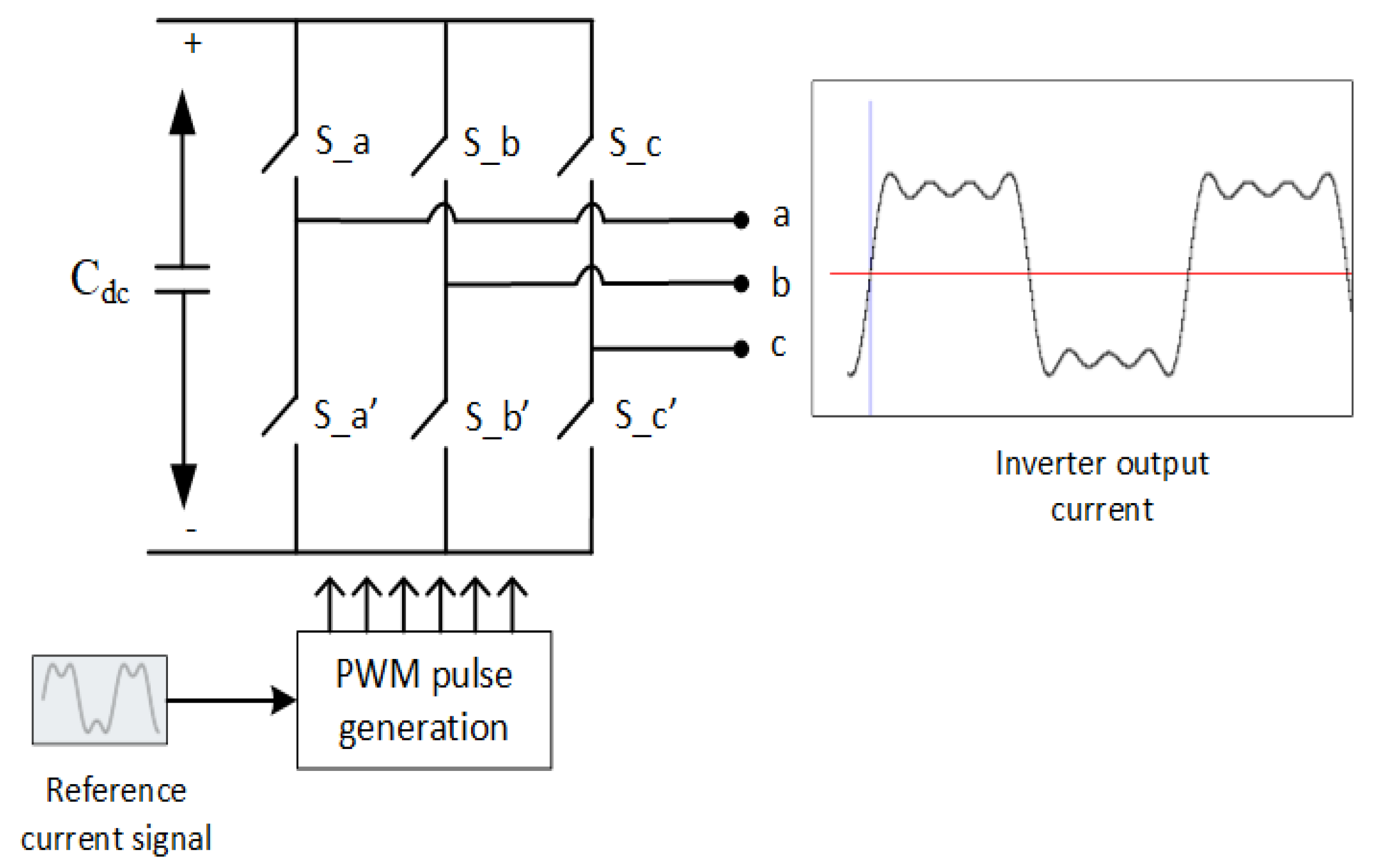
PWM techniques: The primary source of voltage harmonics is PWM techniques that control the inverter. PWM techniques generally need to work at a considerably high switching frequency (fsw) for the switching operation of inverter switches (e.g., IGBTs), which leads to high harmonics at inverter output [41]. The voltage will have a modulated waveform at the inverter output due to the harmonics caused by the load, e.g., non-linear load, and the control techniques used by the inverter;
Effect of the inverter’s DC-side impedance:
  • If a large inductance is used to connect at the DC side of the PV inverter for smoothening the DC, then this type of harmonic source behaves like a current source and is called a current-type harmonic source,
  • If the capacitance is used to connect at the DC side of the PV inverter for smoothening the DC voltage, then this type of harmonic source behaves like a voltage source and is called a voltage-type harmonic source.
Therefore, an inverter with an inductor or capacitor at its DC side may act as a source of current or voltage with harmonic contents [42]. In recent years, most PV inverters have been CSI or current controller VSI [43]. The PV inverter, which converts the DC power (solar PV) to AC power with CSI was found to be more advantageous than VSI. This is because it is easier for a CSI to supply sinusoidal current output with a unity power factor.
A double-frequency voltage ripple on the DC-link voltage creates a sequence of odd harmonics in the output current in the case of single-phase grid-tied PV inverters. This is because the reference current generated by the control technique uses the DC-link voltage. Hence, the inverter output current will also contain the same odd harmonic, as shown in Figure 6. Thus, if these odd harmonics are not addressed before reaching the grid, they will propagate into the grid and impact other equipment connected to the grid [44].
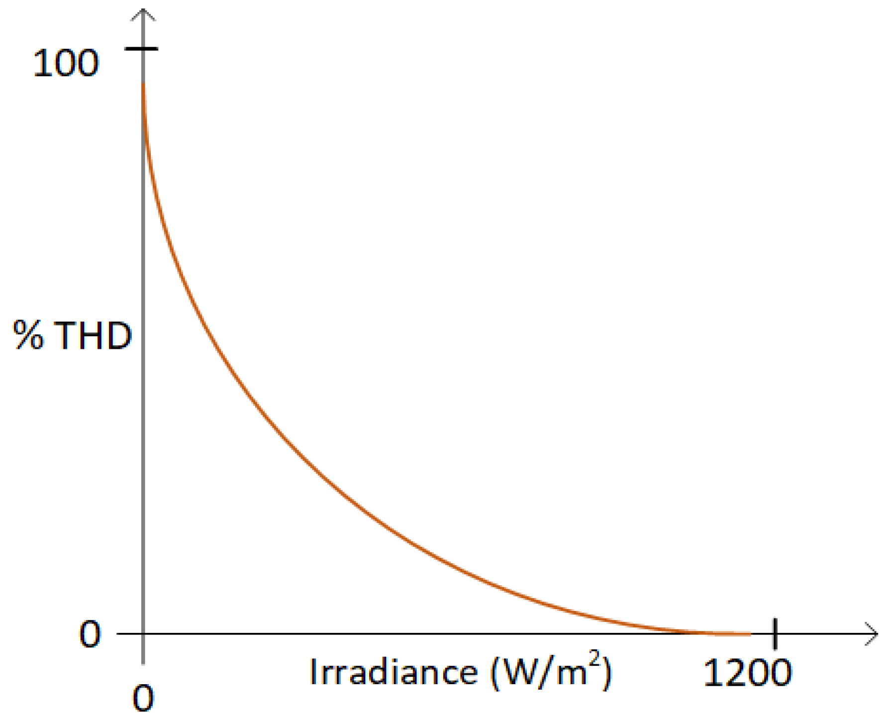
The current harmonics from the PV inverter also depend on the climate variations of the day. During the sunrise and sunset (low irradiance), it is observed that a high level of current THD is produced from the PV inverter [45]. For example, there was a study on a PV plant in the Turkey-Mardin Province in March 2021, in which it was identified that solar irradiance and the power factor (pf) are directly proportional [46]. In addition, the relationship between the pf and THD can be mathematically identified in Equation (2).
pf = k × cos(φ)
where k is the power factor coefficient defined as k = 1/{1 + (THDi)2}; from this, it can be understood that % THD is low at high irradiance, whereas the %THD is very high at low irradiance, which is unacceptable, as shown in Figure 7.
When the PV inverter is connected to the grid, current harmonics from the PV inverter interact with the grid impedance, thus generating voltage harmonics on the PCC [47];
Harmonic levels at PCC also depend on the network load variations and the PV penetration level. The changes in the load connected to the PCC are observed to affect the harmonic voltages generated from the PV inverter. The PV penetration level also affects the harmonics generated by PV inverters [48].

2.3.2. Harmonic Mitigation Strategies

According to IEEE and IEC regulations, the overall harmonic component in the injected current/voltage to the grid from distributed energy resources must be less than 5% [49,50,51]. Several researchers have offered solutions to the harmonics caused by the PV inverters at the PCC of the grid [30,31,32,33,34,35,36,37,38,39,40,41,42,43,44,45,46,47,48]. The most common mitigation technique for PV-inverter harmonics is selective harmonic filters [52], for example, optimal selective harmonic control [53] and frequency-adaptive selective harmonic control [54]. The capacitor banks can also be used as tuned filters by adjusting the reactors if the capacitors are sufficiently rated. On the other hand, passive filters can also be used, but they have the disadvantages of fixed harmonics compensation and resonance problems in the case of LC filters, and they are also huge. Therefore, active power filters (APFs) can be used to overcome the disadvantages of passive filters. APFs have several benefits over passive power filters, like having no harmful resonance and reducing current harmonics induced by non-linear loads and voltage-based grid disruptions. Based on the topology of connection and the requirements, APFs are of different types, namely series, shunt, and hybrid.
Several control strategies were developed for APFs to mitigate the harmonics at PCC [55]. The most critical stage in the control of APF is the development of an acceptable compensatory signal, and the performance of the APF is primarily determined by the reference generation method used, which is mainly of frequency or time domain. From the literature, a summary of the control techniques used to mitigate the harmonics at PCC can be described as follows: (a) the direct power control (DPC) approach has been used to compensate for harmonic current and reactive power in an APF-based grid-connected PV system [56]. In this method, instantaneous quantities of active and reactive powers may be calculated using the source’s measured voltage and current values and compared with reference quantities of active and reactive powers to generate the control signals. However, harmonic-compensating mitigation measures using APF will be an additional cost for the resident or the utility. (b) Another method for harmonic compensation is virtual impedance-based control methods. Virtual impedance can replicate the impact of a physical one without requiring an actual component (an inductor, a resistor, or even a mix of both) to be connected to a system [57]. It mainly avoids using an extra circuit of APF and an additional control system associated with APF. The virtual impedance-based control method utilizes a technique on the grid-connected inverters associated with distributed generators (DGs) [58]. (c) The three primary methodologies utilized in virtual impedance-based control systems are the current control method (CCM), voltage control method (VCM), and hybrid control method (HCM) [59]. In CCM and VCM schemes, harmonic correction is implemented within the control. The CCM scheme is used more in most grid-connected systems for harmonic correction, as real and reactive power references must be converted into current references. The VCM method is more suitable for islanded DGs than grid-connected systems, as CCM cannot support the voltage to loads [60]. Furthermore, due to conflicts between CCM and VCM, they cannot simultaneously manage both voltage and current. As a result, an HCM was created that combines the advantages of both CCM and VCM by combining the cascaded design of a double-loop controller into a single-loop parallel structure with various input branches. Using the HCM scheme, any DG unit can be operated flexibly, such as through local load, harmonic correction mode, and line current harmonics-rejection mode, without the process of harmonics extraction [60]. In addition, with the help of HCM, the shift from grid-connected to islanding mode can be performed without complication. (d) The authors of [61] presented ideas for reducing the negative impacts of double-frequency voltage ripple on the quality of transmitted power. The authors implemented a DBC to control the inverter current in this work. The feature of this controller is that the inverter output is solely dependent on the current reference supplied by the controller. Therefore, the impact of DC-link voltage on the inverter output is eliminated.
In the results discussion section below, we present the simulation results on different use cases to demonstrate the sources of harmonics at PCC in an on-grid PV system.

3. Results and Discussions

This section presents the results of on-grid PV systems with different use cases. the single-line diagram of an on-grid PV system with local loads that was used for this study is presented in Figure 8. It can be seen that the measurements are performed at the grid side, PV side, and load side. These three points cover the PCC of the system where the harmonics were investigated. This study demonstrates the different use cases of the source of harmonics in on-grid PV systems. The following two sub-sections present the results of the MATLAB-based and OPAL-RT-based real-time simulation studies, respectively.

3.1. Simulation Study of On-Grid PV System: Use Cases

The simulation work was performed on the MATLAB/Simulink platform at a sampling time of 50 μ.s with the ode23tb solver. A 500 kW PV system that comprises 5 PV arrays, each with 100 kW capacity, was implemented to have a common DC bus. The PV system with a common DC bus was connected to the grid at low voltage, i.e., 0.4 kV. A two-stage conversion topology was used for PV and grid integration. One stage was DC–DC boost conversion using Perturb and Observe (P&O)-based MPPT. After that, the next stage was DC–AC, which was implemented by a three-phase two-level inverter with a dq-controller. Inverter output was integrated with the grid through an interfacing filter circuit.
Along with the grid integration, a load was connected at the PCC to study the impact of loads as one use case. With the help of the above system, two use cases were investigated with the help of the supporting results. First, an on-grid PV system with constant load at a variable temperature (T) and irradiance (G) was studied. In the second case, an on-grid PV system with variable loads at a constant T and G was studied. For both cases, the relevant results are presented for analysis.

3.1.1. Case 1: On-Grid PV System with Constant Load at Variable Temperature (T) and Irradiance (G)

This sub-section deals with the simulation results of an on-grid PV system with a constant load of 100 kW at variable T and G. Figure 9a represents the effect of the variation in G when T is constant at 40 °C at PCC. The variation in G is considered as 1000→750→500→250→600→1000 in W/m2 at a time interval of 0.2 s. It was identified that the inverter output voltage is constant, where the current varies with respect to the corresponding variation in the irradiance (G). Accordingly, the PV-generated power (PPV) dominantly changes due to the variation in G and more PPV at a high value of G. The dq-control ensured that the DC-link voltage (VDC) was constant throughout except during the dynamics, which can be seen in Figure 9a.
Similarly, results showing the effect of the change of T with a constant G = 1000 W/m2 at PCC are presented in Figure 9b. The variation in T is considered as 40°→35°→30°→25°→40° at a time interval of 0.2 s. From Figure 9b, it is clear that PV-generated power (PPV) is more at T is near 25 °C with a constant DC-link voltage (VDC). Therefore, the temperature T and irradiance G were set at 25 °C and 1000 W/m2, respectively, for further analysis.

3.1.2. Case 2: On-Grid PV System with Variable Loads at Constant Temperature (T) and Irradiance (G)

The results presented in this sub-section show the effect of a load change with constant T (25 °C) and G (1000 W/m2) on the PV generation at PCC. In Figure 10a, PCC voltage (VPCC), PV current (IPV), load current (IL), grid current (Igrid), PV power (PPV), load power (PL), grid power (PLV), and DC-link voltage are shown, respectively. The load power changes can be seen at 1 s, 1.1 s, and 1.2 s. With the designed PV system, as PPV is constant, changes in PLV can be clearly seen with the change in PL. When the PL < PPV, the grid absorbs the remaining power. (A negative sign indicates that the grid is absorbing the power.) At 1.2 s, the load power (PL) increases more than the PV generation, i.e., PL > PPV; then, the grid started supporting the load (PLV is positive, i.e., power reversal).
Similarly, the results in Figure 10b present the effect of non-linear (NL) loads on PV generation at PCC. A rectifier with RL-load was modeled to replicate the effect of nonlinearity. At 0.8 s, an NL load was switched on, and the impact can be seen on the PV current and grid current. A more detailed study was performed on the effect of NL loads on the grid and PV current, which is presented in the next subsection

3.1.3. Harmonic Study with Different Levels of Non-Linear (NL) Loads

This sub-section investigates the harmonic study during the non-linear loads at the PCC. The level of the effect of harmonics is generally computed in the percentage of THD. Figure 11 represents the effect of the change of NL loads on the other parameters, such as PV current (IPV), grid current (ILV), and PCC voltage (VPCC) as well. This was achieved by using two NL loads, i.e., NL load1 at 0.8 s and NL load1 + NL load2 at 0.9 s. With NL load1, the effect on the load current (IL) and the grid current (ILV) can be observed as distorted waveforms. The NL load also has effects on the PCC voltage (VPCC). It is to be noted that, at 0.9 s, two NL loads were switched on (i.e., NL load1 + NL load2), which in turn became a situation in which load power (PL) was more than the PV-generated power (PPV). In this case, the power reversal can be seen with high harmonics in the grid current. Clearly, a high level of NL loads adversely affects PCC voltage, as shown in Figure 11.
Table 3 summarizes the harmonic analysis investigation in this subsection for improved monitoring. Table 3 in scenario 1 represents the effect of an NL load of 572 A with 18.4% THD. Due to this, the waveforms of iPV and iLV are distorted; therefore, the THD of iPV and iLV was found to be 8.5% and 16.8%, respectively. In scenario 2, an NL load of 1114 A with 21.7% THD was switched ON, due to which the waveforms of iPV and iLV were badly distorted, and thus, the THD of iPV and iLV was found to be of 18.3% and 120% respectively. It is clear from this harmonic study analysis that when the connected NL loads are more than a grid-connected PV system can handle, the voltage and current at PCC are severely impacted.

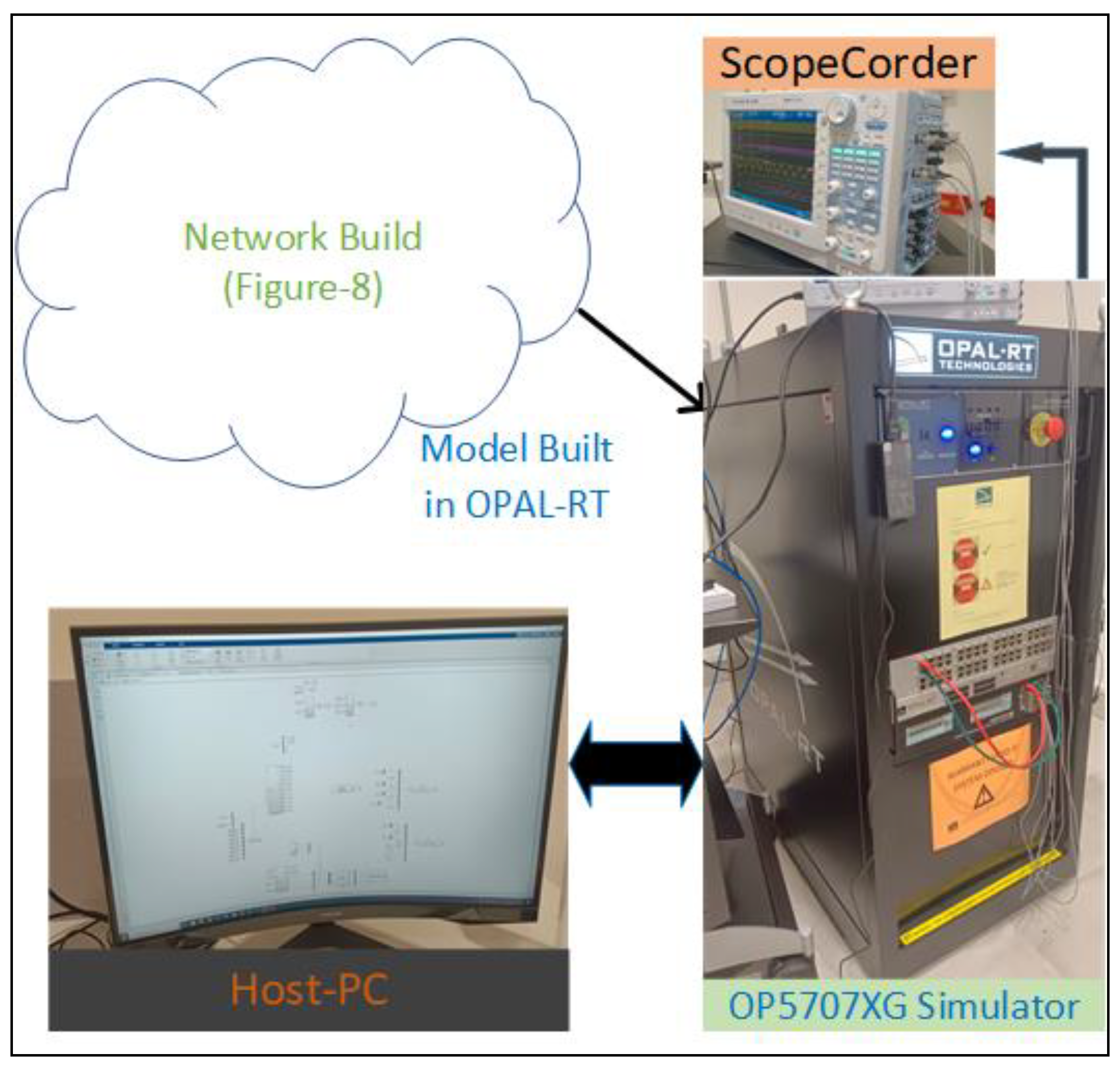
3.2. OPAL-RT Implementation of On-Grid PV System: Use Cases

Offline simulation would simulate electrical events, including harmonics, in a smaller time frame than real physical power systems. For example, in an offline simulation, we would represent the model in minutes to reflect days or weeks of what is happening in the physical system. Therefore, real-time simulation platforms like OPAL-RT capture electrical events, including harmonics, more accurately than offline simulation. Hence, this study evaluated the performance of the on-grid photovoltaic (PV) system under various operating conditions using the real-time digital simulator OPAL-RT (OP5707XG). The use cases such as non-linear loads, arc furnaces, changes in irradiance, and aggressive tuning of inverter control were considered in our studies. A model of the on-grid PV system was developed in MATLAB/Simulink, as shown in Figure 12. Then, the model was compiled using RT-LAB software. This compiled model was then loaded into the OPAL-RT to verify the results in real-time. It is to be noted that phase A was chosen to demonstrate the result, and all parameters are presented in per-unit. The use cases are explained with the supported results.

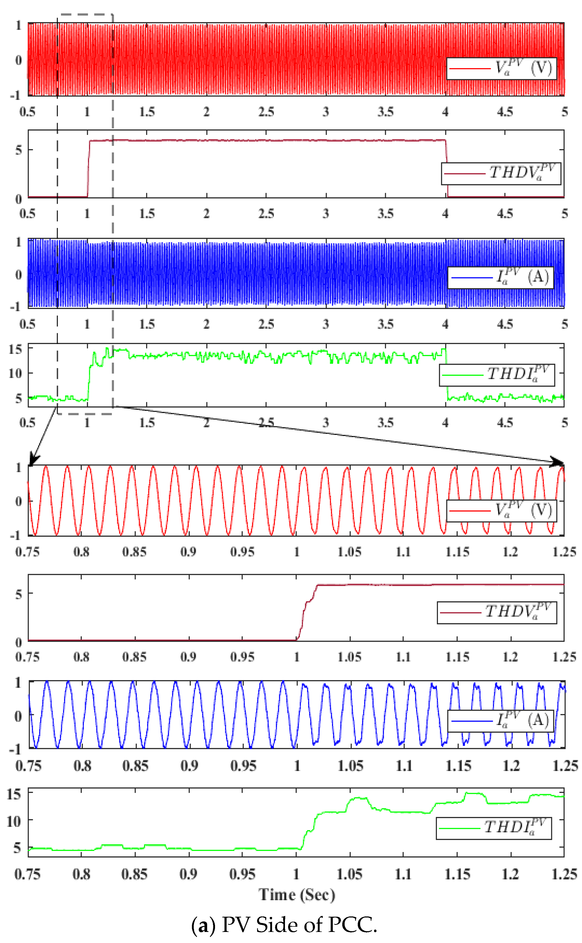
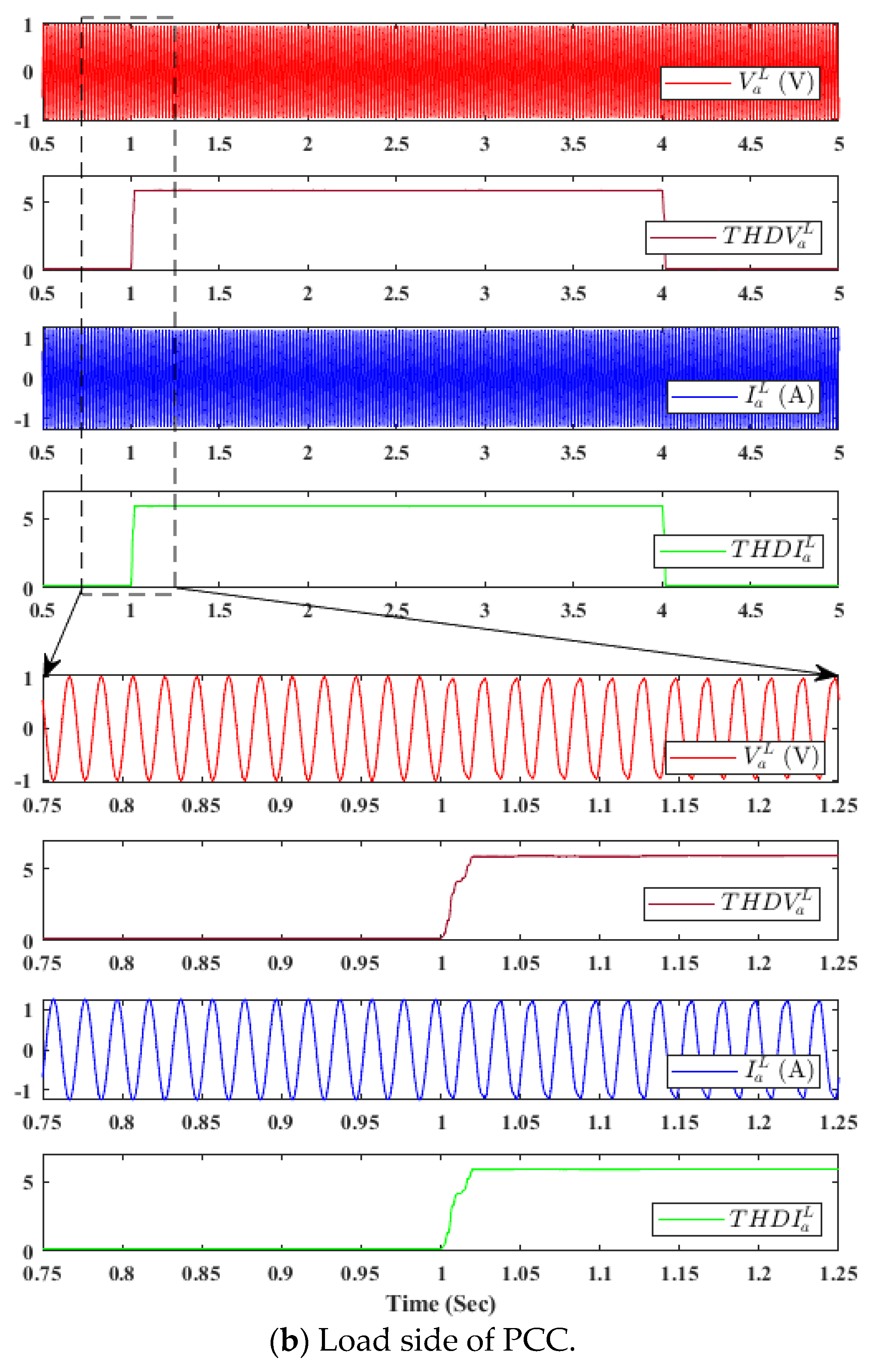
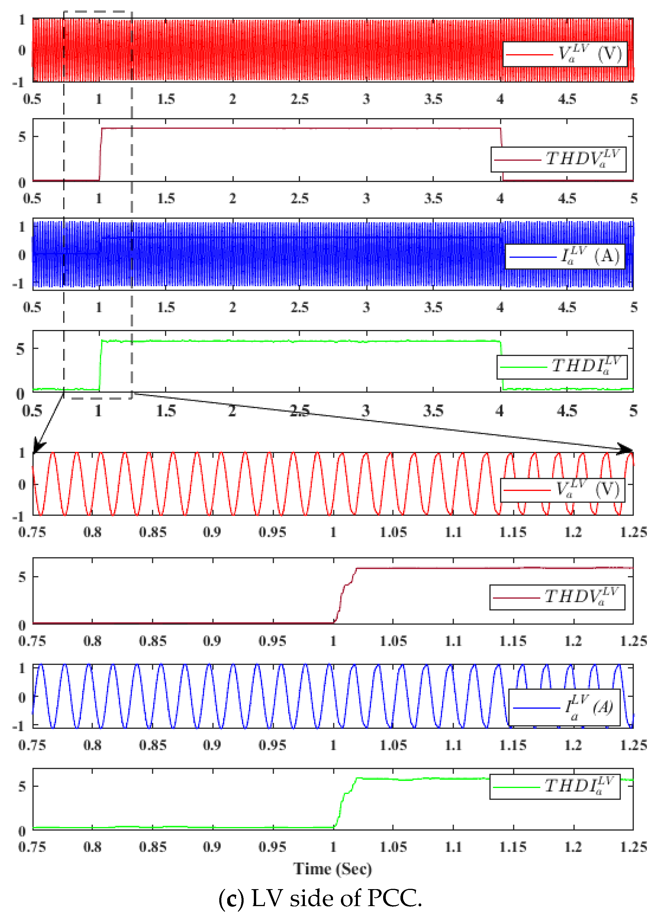
3.2.1. Effect of Non-Linear Loads on THD at PCC

In this case, an 800 A non-linear load, i.e., a rectifier with RL load, was connected at the PCC. Figure 13 demonstrates the results of an on-grid PV system with a non-linear load. The results revealed that before the non-linear load was connected, the THD of the PCC voltage was about 0.8%, while the current THD was 4.9%, 0.8%, and 7.7% at the PV side, load side, and low voltage side, respectively. However, after the non-linear load was connected, the voltage and current waves became severely distorted, increasing THD at the photovoltaic side, load side, and low voltage side, as indicated in Figure 13.

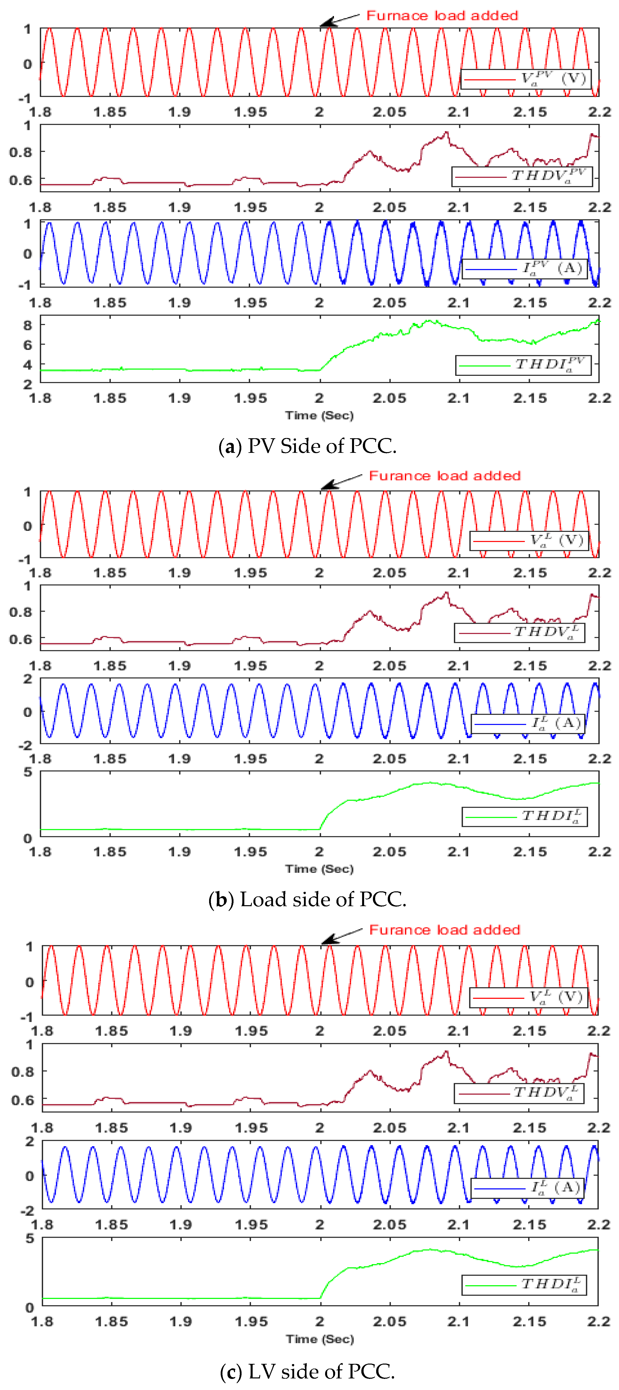
3.2.2. Effect of Furnace Load on THD at PCC

In this case, the performance of an on-grid photovoltaic (PV) system was evaluated in the presence of an arc furnace load. A simulation of the electric arc furnace was modeled using the function blocks in MATLAB for each phase. Three sets of controlled voltage sources and resistive-inductive models were required for a three-phase system. The parameters used in creating an arc furnace are provided in the Appendix A. The results of this test, presented in Figure 14, show a slight increase in the THD at PCC.

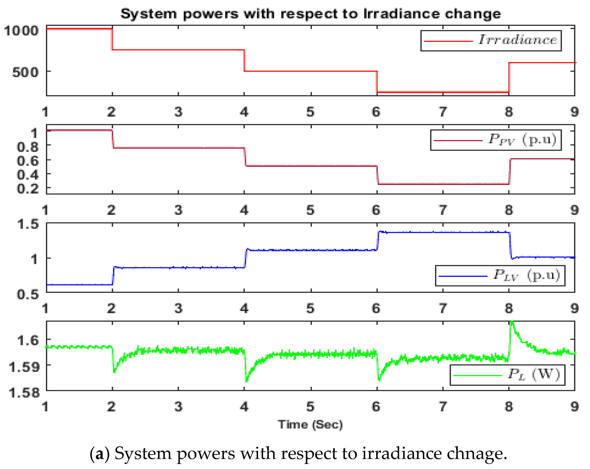
3.2.3. Effect of Change in Irradiance (G) on THD at PCC

The performance of the photovoltaic system was evaluated under climatic changes in terms of varying irradiance levels. This was performed by changing irradiance from 1000 W/m2 to 750 W/m2, 500 W/m2, 250 W/m2, and 600 W/m2 and then back to 1000 W/m2. Irradiance levels can vary due to various environmental factors, such as cloud cover and atmospheric conditions. Understanding the system’s response to these changes is essential for designing and optimizing photovoltaic systems. This test was performed to study the effect of changes in irradiance on the injection of harmonics into the grid. In addition, fluctuations in irradiance can significantly impact the performance of photovoltaic systems. The results indicated a large change in the % THD from the photovoltaic system current, reaching 20% at 250 W/m2 and 7% at 750 W/m, as shown in Figure 15. However, at the low-voltage side and load sides, the change in % THD was comparably low.

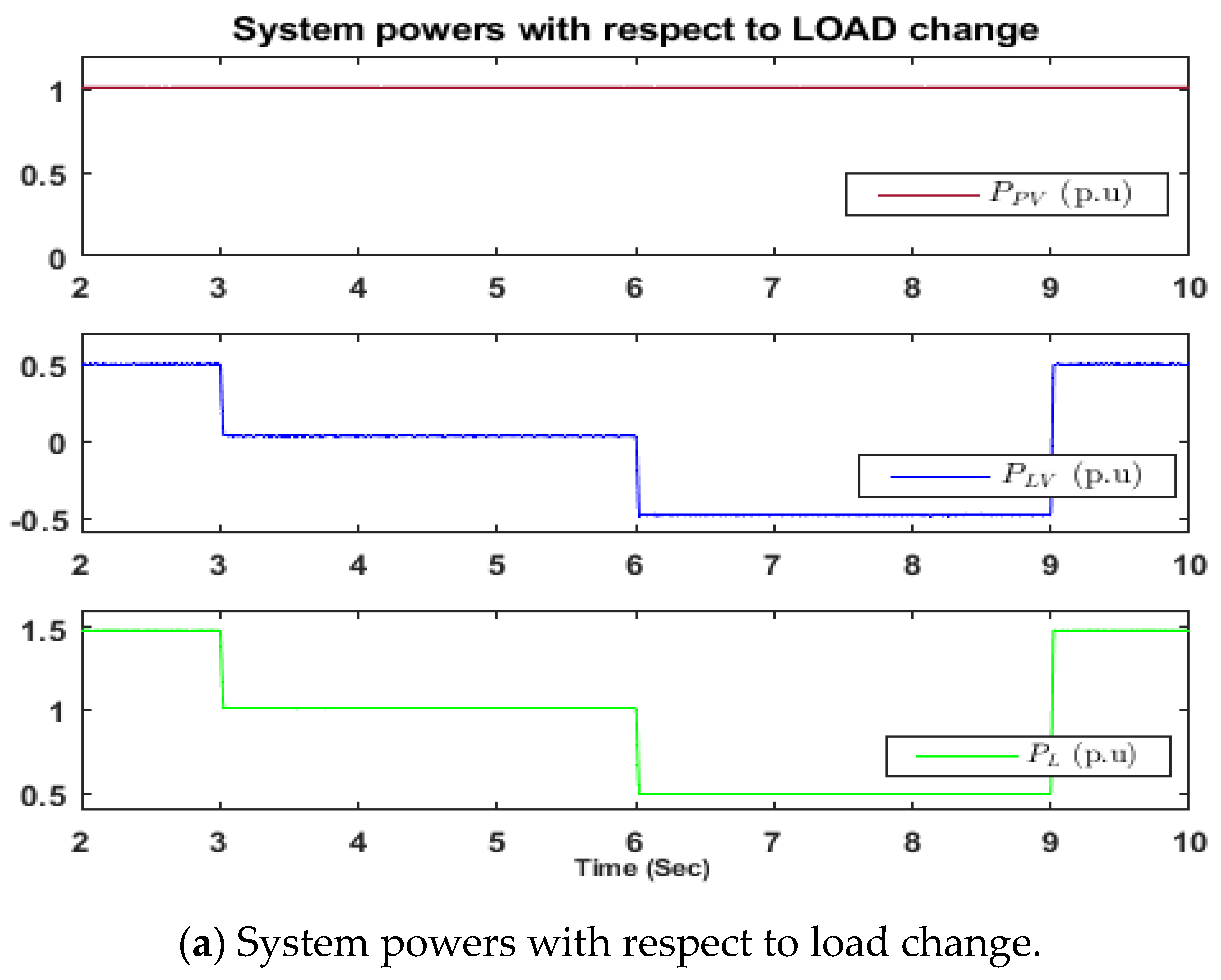
3.2.4. Effect of Load Change on THD at PCC

This test evaluated the influence of load variations and photovoltaic loading on harmonic injection. Three scenarios were simulated, in which the load was varied to represent cases where Ppv < PLoad, Ppv = PLoad, and Ppv > PLoad, as depicted in Figure 16. When Ppv = PLoad, results indicated that the % THD increased slightly at both the photovoltaic side and the load side. However, during this period, power from the LV side was zero; therefore, the THD observed in the current at the LV side was negligible in terms of amplitude. During Ppv > PLoad, the THD of current at the LV side was observed to be more than during Ppv < PLoad.

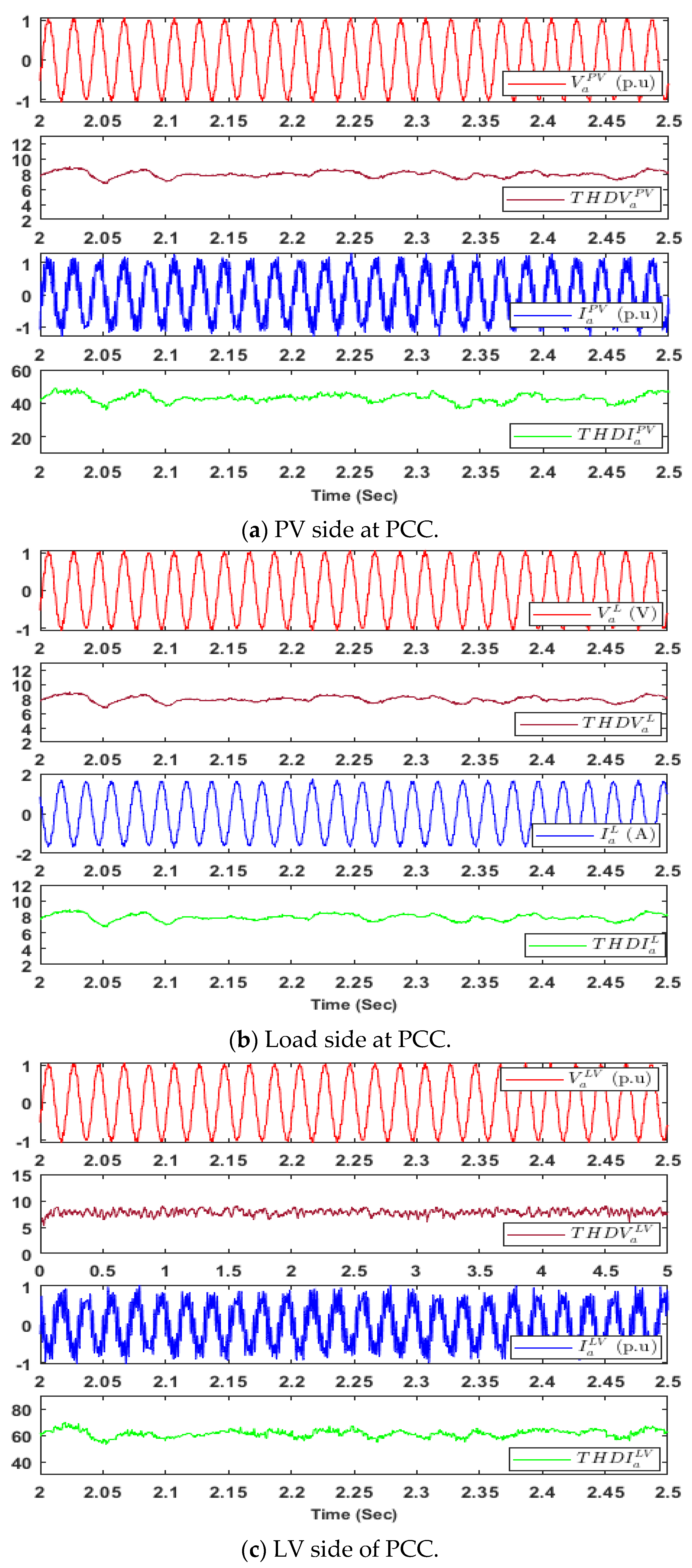
3.2.5. Effect of Change of Tuning Parameters of (kp, ki) of Inverter Controller on THD at PCC

In this case, the authors investigated the effect of the control parameters of PV inverters on the THD at PCC. The tuning of the PV-inverter controller was adjusted to be more aggressive by modifying its tuning parameters as follows:
For the outer-loop tuning parameter: In the normal case, the tuning was kp = 10, ki = 200. In order to see the aggressiveness in control, the tuning was changed to kp = 50, ki = 200. Similarly, for the inner-loop tuning parameter: In the normal case, the tuning was kp = 0.83, ki = 5. In the aggressive case, the tuning was adjusted to kp = 5, ki = 100. The result shows a significant increase in the THD % at all monitoring points, with the LV side current being the most affected, as illustrated in Figure 17.

3.2.6. Effect of Grid-Side Voltage Harmonics on THD at PCC

In this case, the effect of the grid-side background voltage harmonic at PCC was studied. This was performed by injecting a 3rd and 5th harmonics from the grid side at 5% and 3%, respectively. This resulted in approximately 7% harmonics in grid voltage, which affects the currents at PCC with different levels of harmonics at the PV side, load side, and LV (grid) side, as shown in the Figure 18. Figure 18a represents the voltage and currents of the PV side with their respective % THDs. The voltage THD is 7%, whereas current THD is around 15% at the PV side. Similarly, Figure 18b represents the voltage and currents of the load side with their respective % THDs. The voltage THD is 7%, whereas current THD is 7.5%. On the other hand, Figure 18c shows the voltage and current of the LV side with their respective % THDs. It can be seen that at the LV side, voltage THD is 7%, whereas current THD is 7.5%. From this study, it is shown that, due to the grid-side background voltage harmonics, the PV-side current is more affected with harmonics.
A comparison of % THD variation in all the use cases from the test study is summarized in Table 4. The results from more effective use cases are compared in Table 4. These use cases are non-linear loads, furnace loads, and the control parameter change. A normal case with a linear load at standard temperature (T = 25 °C) and irradiance (G = 1000 W/m2) was considered for comparison. From the table, a non-linear load affects both PV and LV sides significantly. A furnace load slightly impacts THD at PCC compared to the other use cases. However, during the changing of the control parameters, a drastic increase in the THD at both PV and LV sides was observed.

4. Conclusions

This paper addresses the technical aspects of on-grid connected solar PV systems, its components, and their roles in on-grid PV systems in the LV network. A comparative study on the type of PV inverters, such as string, central, power amplifier, and micro-inverters, with their advantages and disadvantages is presented in this paper. From the literature review and offline and real-time simulation work, we can draw the following conclusions: The main sources of harmonics at PCC are PWM switching, the inverter’s DC-side impedance, double-frequency voltage ripple in the DC-link voltage, climate variation, and load variations. Simulation studies show that the presence of non-linear loads significantly impacts the quality of the electric power supply and the performance of the power system. In particular, non-linear loads generate harmonic currents that distort voltage and current waveform, reducing the efficiency and stability of the power system. The obtained results provide valuable insights into the behavior of photovoltaic systems under non-linear load conditions. During the low irradiance, the % THD in current at PV is significant, affecting the overall THD. This emphasizes the importance of considering the impact of changes in irradiance on the performance of photovoltaic systems and highlights the significance of real-time monitoring and control to ensure optimal performance. The real-time simulation study shows that inverter controller settings, such as gains of the proportional integral (PI) controller (kp, ki) parameters, play a crucial role in THD levels at PCC from the PV inverter. For example, during the changing of the control parameters, the % THD in current at the PV side of the PCC was at 40% and 60% in the current at LV side of the PCC. Therefore, a properly tuned controller would significantly reduce the harmonic effect at the inverter output.
From the literature and simulation study that was performed in this work, we can conclude that the intermittency in PV output and connected loads (non-linear) would have a significant contribution to the harmonics at PCC. Therefore, this study conducted to assess the impact of photovoltaic output variations and loads on harmonics at PCC is extremely important for the design and implementation process of mitigation solutions to be deployed to improve the power quality of an on-grid PV system.
Future research scope: Based on our findings, a number of lines of inquiry are opened, with the following areas of focus: In on-grid solar PV systems, harmonics may be efficiently reduced by using advanced control techniques that react to changing conditions. Investigating the best ways to design an ideal system while considering the abovementioned factors can create standards for choosing an inverter, sizing a PV array, and designing a grid interface that reduces harmonics and maximizes power quality. By conducting field studies and experimental validations based on the parameters identified, it is possible to obtain useful knowledge and confirm the viability of the suggested mitigation solutions. The results’ relevance to actual on-grid solar PV systems may be further improved by collecting and analyzing data from real-world scenarios. The knowledge of harmonics in on-grid solar PV systems will be furthered by following these future research avenues, which will also make it easier to create powerful power-quality-enhancement solutions.

Author Contributions

T.A.N., conceptualization, methodology, validation, investigation, software, and writing—original draft; H.M.A.A.A., investigation, conceptualization, methodology, validation, and software; A.A.-S., resource and data curation; S.K.S., resources, supervision, and writing—reviewing and editing; T.G., supervision, project administration, resources, and writing—reviewing and editing. All authors have read and agreed to the published version of the manuscript.

Funding

This research received no external funding.

Data Availability Statement

Not applicable.

Conflicts of Interest

The authors declare no conflict of interest.

Appendix A

System parameters: Grid side: 11 kV, 50 Hz (with 11/0.4 kV, 50 Hz transformer); load side: 1246 kW (linear and non-linear); PV Side: PV inverters: 3 ph, 400 V, 50 Hz; PV arrays: 100 kW.
Parameters used for arc furnace: Arc power of 19 kW, an arc current of 5 kA, a base threshold voltage of 200 V, a modulation index of 0.2, and a coupling network of 0.01 Ω and 1 mH.

References

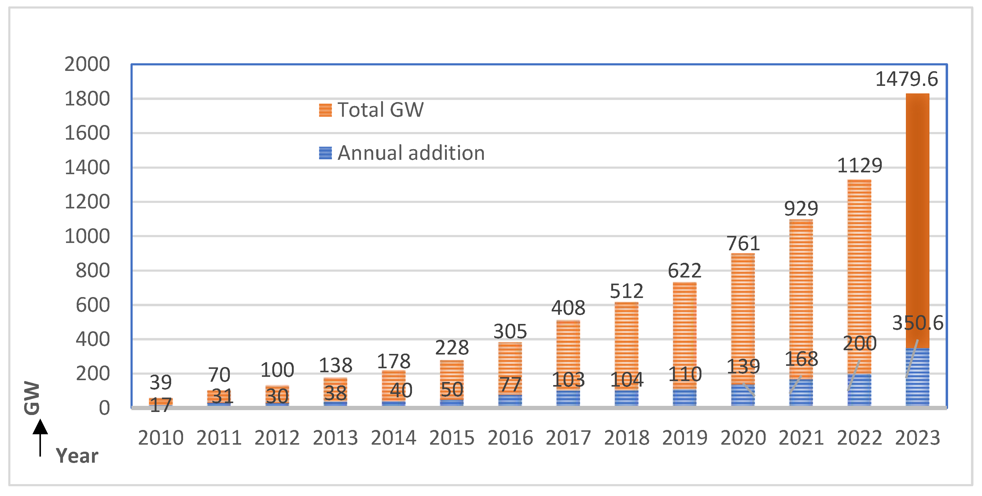
  1. Renewables 2022 Global Status Report. Available online: https://www.ren21.net/wp-content/uploads/2019/05/GSR2023_GlobalOverview_Full_Report_with_endnotes_web.pdf (accessed on 4 August 2023).
  2. Available online: https://www.pv-magazine.com/2023/02/16/global-solar-installations-may-hit-350-6-gw-in-2023-says-trendforce/ (accessed on 1 August 2023).
  3. IEEE Std 1100-2005; IEEE Recommended Practice for Powering and Grounding Electronic Equipment-Redline. IEEE Standards Association: Piscataway, NJ, USA, 2006.
  4. Alsaif, A.K. Challenges and benefits of integrating renewable energy technologies into AC power system Grid. Am. J. Eng. Res. 2017, 6, 95–100. [Google Scholar]
  5. Jiao, S.; Raj, K.; Rajashekara, K. A Novel DROGI Algorithm for Non-linear Unbalanced Load Compensation using Four-leg Converter. In Proceedings of the 2020 IEEE Applied Power Electronics Conference and Exposition (APEC), New Orleans, LA, USA, 15–19 March 2020; pp. 3282–3286. [Google Scholar]
  6. Reza, M.H.; Shobug, M.A. Efficiency Evaluation of P&O MPPT Technique used for Maximum Power Extraction from Solar Photovoltaic System. In Proceedings of the 2020 IEEE Region 10 Symposium (TENSYMP), Dhaka, Bangladesh, 5–7 June 2020; pp. 1808–1811. [Google Scholar]
  7. Patel, V.; Patel, J.J. Power quality improvement of grid using solar photovoltaic farm. In Proceedings of the 2017 Innovations in Power and Advanced Computing Technologies (i-PACT), Vellore, India, 21–22 April 2017; pp. 1–6. [Google Scholar]
  8. Ortiz, A.; Gherasim, C.; Manana, M.; Renedo, C.J.; Eguiluz, L.I.; Belmans, R.J. Total harmonic distortion decomposition depending on distortion origin. IEEE Trans. Power Deliv. 2005, 20, 2651–2656. [Google Scholar]
  9. Papaioannou, I.T.; Bouhouras, A.S.; Marinopoulos, A.G.; Alexiadis, M.C.; Demoulias, C.S.; Labridis, D.P. Harmonic impact of small photovoltaic systems connected to the LV distribution network. In Proceedings of the 2008 5th International Conference on the European Electricity Market, Lisboa, Portugal, 28–30 May 2008; pp. 1–6. [Google Scholar]
  10. Schlabbach, J. Harmonic current emission of photovoltaic installations under system conditions. In Proceedings of the 2008 5th International Conference on the European Electricity Market, Lisboa, Portugal, 28–30 May 2008; pp. 1–5. [Google Scholar]
  11. Liu, J. The main factors influencing the harmonic level of grid connected photovoltaic analysis. Electr. Technol. 2009, 12, 66–67. [Google Scholar]
  12. Schlabbach, J.; Grob, A.; Chicco, G. Influence of Harmonic System Voltages on the Harmonic Current Emission of Photovoltaic Inverters. In Proceedings of the 2007 International Conference on Power Engineering, Energy and Electrical Drives, Setubal, Portugal, 12–14 April 2007; pp. 545–550. [Google Scholar]
  13. Gan, C.K.; Tan, P.H.; Khalid, S. System Performance Comparison Between Crystalline and Thin-Film Technologies under Different Installation Conditions. In Proceedings of the 2013 IEEE Conference on Clean Energy and Technology (CEAT), Langkawi, Malaysia, 18–20 November 2013; pp. 362–367. [Google Scholar]
  14. Rodriguez, J.R.; Ruiz, F.; Biel, D.; Guinjoan, F. Simulation and analysis of distributed PV generation in a LV network using MATLAB-Simulink. In Proceedings of the 2010 IEEE International Symposium on Circuits and Systems, Paris, France, 30 May–2 June 2010; pp. 3–6. [Google Scholar]
  15. Available online: https://greenridgesolar.com/2020/11/types-of-solar-inverters/ (accessed on 4 August 2023).
  16. Available online: https://sinovoltaics.com/learning-center/inverters/central-inverters/ (accessed on 1 August 2023).
  17. Available online: https://energyresearch.ucf.edu/consumer/solar-technologies/solar-electricity-basics/cells-modules-panels-and-arrays/ (accessed on 4 August 2023).
  18. Zeb, K.; Uddin, W.; Khan, M.A.; Ali, Z.; Ali, M.U.; Christofides, N.; Kim, H.J. A comprehensive review on inverter topologies and control strategies for grid connected photovoltaic system. Renew. Sustain. Energy Rev. 2018, 94, 1120–1141. [Google Scholar]
  19. Attanasio, R.; Cacciato, M.; Gennaro, F.; Scarcella, G. Review on single-phase PV inverters for grid-connected applications. In Proceedings of the 4th IASME/WSEAS, International Conference on Energy, Environment, Ecosystems and Sustainable Development (EEESD’08), Algarve, Portugal, 11–13 June 2008. [Google Scholar]
  20. Gerardo, V.G.; Raymundo, M.R.P.; Miguel, S.Z.J. High efficiency single-phase transformer-less inverter for photovoltaic applications. Ing. Investig. Tecnol. 2015, 16, 173–184. [Google Scholar] [CrossRef]
  21. Anzalchi, A.; Sundararajan, A.; Moghadasi, A.; Sarwat, A. High-Penetration Grid-Tied Photovoltaics: Analysis of power quality and feeder voltage profile. IEEE Ind. Appl. Mag. 2019, 25, 83–94. [Google Scholar]
  22. IEA International Energy Agency. High Penetration of PV in Local Distribution Grids: Case Study Collection; IEA International Energy Agency: Paris, France, 2014. [Google Scholar]
  23. Yaskawa Solectria Solar. Total Harmonics Distortion in Grid-Connected Photovoltaic Inverters and Strategies for Their Mitigation; Yaskawa Solectria Solar: Lawrence, MA, USA.
  24. Varatharajan, A.; Schoettke, S.; Meyer, J.; Abart, A. Harmonic emission of large PV installations case study of a 1 MW solar campus. In Proceedings of the ICREPQ International Conference on Renewable Energies and Power Quality, Cordoba, Spain, 8–10 April 2014; pp. 8–10. [Google Scholar]
  25. Xiong, L.; Nour, M.; Shahin, M. Harmonic analysis of high penetration level of Photovoltaic generation in distribution network and solution studies. In Proceedings of the 2019 8th International Conference on Modeling Simulation and Applied Optimization (ICMSAO), Manama, Bahrain, 15–17 April 2019; pp. 1–5. [Google Scholar]
  26. Aprilia, E.C. Modelling of Photovoltaic (PV) Inverter for Power Quality Studies. Master’s Thesis, Department of Electrical Engineering, Eindhoven University of Technology, Eindhoven, The Netherlands, 2012. [Google Scholar]
  27. Anzalchi, A.; Sundararajan, A.; Moghadasi, A.; Sarwat, A. Power quality and voltage profile analyses of high penetration grid-tied photovoltaics: A case study. In Proceedings of the 2017 IEEE Industry Applications Society Annual Meeting, Cincinnati, OH, USA, 1–5 October 2017; pp. 1–8. [Google Scholar]
  28. Abad, G. (Ed.) Power Electronics and Electric Drives for Traction Applications; John Wiley & Sons: Hoboken, NJ, USA, 2016. [Google Scholar]
  29. Zeng, Z.; Yang, H.; Zhao, R.; Cheng, C. Topologies and control strategies of multi-functional grid-connected inverters for power quality enhancement: A comprehensive review. Renew. Sustain. Energy Rev. 2013, 24, 223–270. [Google Scholar]
  30. Surprenant, M.; Hiskens, I.; Venkataramanan, G. Phase locked loop control of inverters in a microgrid. In Proceedings of the 2011 IEEE Energy Conversion Congress and Exposition, Phoenix, AZ, USA, 17–22 September 2011; pp. 667–672. [Google Scholar]
  31. Castilla, M.; Miret, J.; Matas, J.; de Vicuna, L.G.; Guerrero, J.M. Linear Current Control Scheme with Series Resonant Harmonic Compensator for Single-Phase Grid-Connected Photovoltaic Inverters. IEEE Trans. Ind. Electron. 2008, 55, 2724–2733. [Google Scholar] [CrossRef]
  32. Huerta, F.; Pizarro, D.; Cobreces, S.; Rodriguez, F.J.; Giron, C.; Rodriguez, A. LQG servo controller for the current control of LCL grid-connected voltage-source converters. IEEE Trans. Ind. Electron. 2011, 59, 4272–4284. [Google Scholar] [CrossRef]
  33. Cortajarena, J.A.; Barambones, O.; Alkorta, P.; De Marcos, J. Sliding mode control of grid-tied single-phase inverter in a photovoltaic MPPT application. Sol. Energy 2017, 155, 793–804. [Google Scholar]
  34. Sharma, R.; Suhag, S. Feedback linearization-based control for weak grid-connected PV system under normal and abnormal conditions. Front. Energy 2020, 14, 400–409. [Google Scholar] [CrossRef]
  35. Mohamed, S.R.; Jeyanthy, P.A.; Devaraj, D. Hysteresis-based voltage and current control techniques for grid connected solar photovoltaic systems: Comparative study. Int. J. Electr. Comput. Eng. (IJECE) 2018, 8, 2671–2681. [Google Scholar] [CrossRef]
  36. Hong, W.; Tao, G. An Adaptive Control Scheme for Three-phase Grid-Connected Inverters in Photovoltaic Power Generation Systems. In Proceedings of the Annual American Control Conference (ACC), Milwaukee, WI, USA, 27–29 June 2018; pp. 899–904. [Google Scholar]
  37. Ghasemi, A.; Sedighizadeh, M.; Fakharian, A.; Nasiri, M.R. Intelligent voltage and frequency control of islanded micro-grids based on power fluctuations and communication system uncertainty. Int. J. Electr. Power Energy Syst. 2022, 143, 108383. [Google Scholar] [CrossRef]
  38. Fang, Y.; Zhu, Y.; Fei, J. Adaptive intelligent sliding mode control of a photovoltaic Grid-connected inverter. Appl. Sci. 2018, 8, 1756. [Google Scholar]
  39. Naidu, T.A.; Arya, S.R.; Maurya, R. Phase Locked Loop Based on Third Order SSI for Compensation of Voltage-Related Power Quality Issues Using DVR. Electr. Power Compon. Syst. 2019, 47, 329–344. [Google Scholar] [CrossRef]
  40. Naidu, T.A.; Arya, S.R.; Maurya, R.; Padmanaban, S. Performance of DVR Using Optimized PI Controller Based Gradient Adaptive Variable Step LMS Control Algorithm. IEEE J. Emerg. Sel. Top. Ind. Electron. 2021, 2, 155–163. [Google Scholar] [CrossRef]
  41. De Jaeger, E.; Koo, K.L.; Juncheng, L.; Chan, K.; Desmet, J.; Zavoda, F.; Bollen, M.H.J.; Ronnberg, S.K.; Meyer, J.; Council on Large Electric Systems (CIGRE). Power Quality and EMC Issues with Future Electricity Networks; Council on Large Electric Systems (CIGRE): Paris, France, 2018. [Google Scholar]
  42. Li, D.; Tian, J. A novel active power filter for the voltage-source type harmonic source. In Proceedings of the 2008 International Conference on Electrical Machines and Systems, Wuhan, China, 17–20 October 2008; pp. 2077–2080. [Google Scholar]
  43. Ertasgin, G. Low-Cost Current-Source 1-Ph Photovoltaic Grid-Connected Inverter. Ph.D. Thesis, University of Adelaide, Adelaide, Australia, 2010. [Google Scholar]
  44. Du, Y.; Lu, D.D.-C.; Chu, G.M.L.; Xiao, W. Closed-form solution of time-varying model and its applications for output current harmonics in two-stage PV inverter. IEEE Trans. Sustain. Energy 2014, 6, 142–150. [Google Scholar]
  45. Block, P.A.B.; Salamanca, H.L.L.; Teixeira, M.D.; Dahlke, D.B.; Shiono, O.M.; Donadon, A.R.; Camargo, J.C. Power quality analyses of a large-scale photovoltaic system. In Proceedings of the 2014 5th International Renewable Energy Congress (IREC), Hammamet, Tunisia, 25–27 March 2014; pp. 1–6. [Google Scholar]
  46. Cangi, H.; Adak, S. Quality Problems in Low İrradiance at Grid Connected PV Solar System. July 2022, pp. 1–11. Available online: https://www.researchsquare.com/article/rs-1812960/v1 (accessed on 4 August 2023).
  47. Hamid, M.I.; Anwari, M.; Gaonkar, D.N. Single-phase photovoltaic-inverter operation characteristic in distributed generation system. In Distributed Genaration; INTECH: Houston, TX, USA, 2010; pp. 141–165. [Google Scholar]
  48. Ibrahem, H.; Yehia, D.M.; Azmy, A.M. Power Quality Investigation of Distribution Networks with High Penetration of Solar Energy. In Proceedings of the 2019 21st International Middle East Power Systems Conference (MEPCON), Cairo, Egypt, 17–19 December 2019; pp. 1193–1198. [Google Scholar]
  49. IEEE Std 519-2022; IEEE Recommended Practices and Requirements for Harmonic Control in Electrical Power Systems. IEEE Standards Association: Piscataway, NJ, USA, 2022.
  50. IEEE Std 1547-2003; IEEE Standard for Interconnecting Distributed Resources with Electric Power Systems. IEEE Standards Association: Piscataway, NJ, USA, 2009.
  51. IEC 61727-2004; Photovoltaic (PV) Systems—Characteristics of the Utility Interface. IEC-International Electrotechnical Commission: Geneva, Switzerland, 2004.
  52. Matre, M. Harmonics in Photovoltaic Inverters & Mitigation Techniques; Sterling & Wilson: Mumbai, India, 2020. [Google Scholar]
  53. Zhou, K.; Yang, Y.; Blaabjerg, F.; Wang, D. Optimal selective harmonic control for power harmonics mitigation. IEEE Trans. Ind. Electron. 2014, 62, 1220–1230. [Google Scholar]
  54. Yang, Y.; Zhou, K.; Wang, H.; Blaabjerg, F.; Wang, D.; Zhang, B. Frequency adaptive selective harmonic control for grid-connected inverters. IEEE Trans. Power Electron. 2014, 30, 3912–3924. [Google Scholar]
  55. Liang, X.; Andalib-Bin-Karim, C. Harmonic mitigation through advanced control methods for grid-connected renewable energy sources. In Proceedings of the 2017 IEEE Industry Applications Society Annual Meeting, Cincinnati, OH, USA, 1–5 October 2017; pp. 1–12. [Google Scholar]
  56. Chaoui, A.; Krim, F.; Gaubert, J.-P.; Rambault, L. DPC controlled three-phase active filter for power quality improvement. Int. J. Electr. Power Energy Syst. 2008, 30, 476–485. [Google Scholar] [CrossRef]
  57. Munir, S.; Li, Y.W. Residential distribution system harmonic compensation using PV interfacing inverter. IEEE Trans. Smart Grid 2013, 4, 816–827. [Google Scholar] [CrossRef]
  58. Li, Y.W.; He, J. Distribution system harmonic compensation methods: An overview of DG-interfacing inverters. IEEE Ind. Electron. Mag. 2014, 8, 18–31. [Google Scholar]
  59. Liang, X.; Andalib-Bin-Karim, C. Harmonics and mitigation techniques through advanced control in grid-connected renewable energy sources: A review. IEEE Trans. Ind. Appl. 2018, 54, 3100–3111. [Google Scholar] [CrossRef]
  60. He, J.; Li, Y.W. Hybrid voltage and current control approach for DG-grid interfacing converters with LCL filters. IEEE Trans. Ind. Electron. 2012, 60, 1797–1809. [Google Scholar]
  61. Salem, M.; Atia, Y. Control scheme towards enhancing power quality and operational efficiency of single-phase two-stage grid-connected photovoltaic systems. J. Electr. Syst. Inf. Technol. 2015, 2, 314–327. [Google Scholar]
Figure 1. Solar PV global capacity and annual additions [1,2].
Energies 16 06398 g001
Figure 2. (a) Typical configuration of the on-grid PV system; (b) power-converter circuit with anti-parallel diode-based IGBTs.
Energies 16 06398 g002
Figure 3. On-grid PV-inverter topologies based on conversion stages: (a) single-stage conversion topology and (b) two/multi-stage conversion topology.
Energies 16 06398 g003
Figure 4. On-grid PV-inverter topologies based on the transformer. (a) PV-inverter topology with line frequency transformer. (b) PV-inverter topology with high-frequency transformer [20].
Energies 16 06398 g004
Figure 5. Control strategy for on-grid PV inverter: (a) control structure for single-stage conversion topology and (b) control structure for two-stage conversion topology. Note that * represents the reference value.
Energies 16 06398 g005
Figure 6. Effect of the presence of odd harmonics in the reference current signal in the inverter output current.
Energies 16 06398 g006
Figure 7. Relationship between solar PV irradiance (W/m2) and %THD [46].
Energies 16 06398 g007
Figure 8. Single-line diagram of an on-grid PV system with local loads.
Energies 16 06398 g008
Figure 9. Results presenting the effect of temperature (T) and irradiance (G) variation on PV generation at PCC (a) at constant T = 40 °C and variable G (1000→750→500→250→600→1000 in W/m2) and (b) at irradiance G = 1000 W/m2 and variable T (40→35→30→25→40 in deg. C).
Energies 16 06398 g009
Figure 10. Results presenting the effect of the load change on PV generation at PCC with a constant T = 25 °C and G = 1000 W/m2. (a) Linear loads and (b) non-linear loads.
Energies 16 06398 g010
Figure 11. Results presenting the effect of NL-load change on PV generation at PCC.
Energies 16 06398 g011
Figure 12. Test setup with an OPAL-RT simulator.
Energies 16 06398 g012
Figure 13. Test results showing the effect of non-linear load. (a) PV side; (b) load side; (c) LV side.
Energies 16 06398 g013aEnergies 16 06398 g013b
Figure 14. Test results showing the effect of the arc furnace. (a) PV side; (b) load side; (c) LV side.
Energies 16 06398 g014
Figure 15. Test results showing the effect of irradiance change. (a) Change of power during change of irradiance; (b) PV side; (c) LV side.
Energies 16 06398 g015aEnergies 16 06398 g015b
Figure 16. Test results showing the effect of load change. (a) Load power change; (b) PV side; (c) load side; (d) LV side.
Energies 16 06398 g016aEnergies 16 06398 g016bEnergies 16 06398 g016c
Figure 17. Test results showing the effect of the control parameters change. (a) PV side; (b) load side; (c) LV side.
Energies 16 06398 g017
Figure 18. Test results showing the effect of the grid side harmonics. (a) PV side; (b) load side; (c) LV side.
Energies 16 06398 g018aEnergies 16 06398 g018bEnergies 16 06398 g018c
Table 1. Comparison of the types of PV inverters with their advantages and disadvantages [15,16].
S. No.Types of PV InverterAdvantagesDisadvantages
1String inverters: string inverters function by connecting a series of solar panels to a single inverter, transforming the whole DC input to AC output. Most traditional and stable/reliable;
Less expensive;
Because string inverters are strategically positioned on the side of a house, they are easy to monitor, repair, and replace.
Shading on one solar panel would reduce the power output of the entire string: string inverters are less efficient in optimizing solar energy production because they are connected to a complete string of solar panels.
String inverters only provide total-system monitoring. This can be a drawback for diagnosing solar output concerns and bad for solar customers who desire a more detailed degree of monitoring.
2Central inverters: central inverters are similar to the string inverters in construction. Central inverters are used in such applications where multiple strings of PV panels are combined in parallel for more power to be converted from the DC to AC grid.Lower cost;
Credibility due to presence for a long time and use in the market;
Ability to produce more power;
Reliable, as central inverters are placed in a protective environment.
Potential for a single point of failure: even if a single panel is shaded or fails for any reason, it will affect the entire system’s performance.
There is a higher risk factor because of the high rating of the produced DC voltage, which could be life-threatening for operators, and there is a higher replacement cost.
3Power optimizers + inverters: each solar panel has a power optimizer at its back that synchronizes with a string inverter to convert DC to AC.Because power optimizers can condition the DC energy supplied by each solar panel, a partially shaded solar panel would not affect the output of the entire string as it would with a traditional string inverter system;
In addition to system-level monitoring, power optimizers offer the advantage of providing panel-level monitoring.
These are more expensive than string inverters, as they require addition of optimizer. If one plans to increase one’s solar panel system in the future, more power optimizers and possibly more string inverters will be needed. As power optimizers are positioned on the roof, repairing and replacing them is also more difficult.
4Microinverters: microinverters are the most recent advancement in solar inverter technology, converting DC to AC directly from the back of each solar panel.Since each microinverter handles the DC-to-AC conversion on each panel, shading on individual panels has a negligible influence on the system;
Microinverters are very simple to add to a solar system later: a microinverter is all that is needed to put on the back of any new solar panels added to the system;
Like power optimizers, microinverters enable panel-level solar system monitoring, making any solar output concerns more simply and precisely diagnosed.
The costliest solar inverter option is the microinverters. However, the benefits might easily outweigh the expenses, particularly if shadowing is a concern. Because microinverters are mounted on the back of each solar panel, they are more challenging to repair or replace if they fail.
Table 2. Features of the control techniques in an on-grid PV systems.
S. No.Names of ControlFeatures of the Control Techniques in On-Grid PV Systems
1PLL-based control [30]Grid synchronization, grid frequency measurement, and inverter phase reference.
2PR control [31]Capable of reducing the steady-state error by offering extra gain at the resonant frequency.
3LQG control [32]Zero steady-state tracking error, channel decoupling, and noise cancellation.
4SMC [33]Less requirement of system parameters, insensitivity to parameter variations, and external disturbance rejection.
5Feedback linearization control [34]Voltage support and under fault conditions, tackles transient behavior.
6Hysteresis control [35]Simple and easy to implement and robust in current control performance with stability, fast response, and ability to control peak current.
7Adaptive control [36]Efficient handling of system uncertainties and disturbances.
8Intelligent control [37]It can handle voltage and frequency deviations, power fluctuations, and communication system delays.
9Mixed: Adaptive intelligent sliding mode control [38]Estimates the system uncertainties and has grid connection reliability, less voltage tracking error, and robustness to environmental variations
Table 3. Harmonics study at different NL loads.
Name of ParameterScenario 1 (NL-Load1)Scenario 2 (NL-Load1 + Nl-Load2)
Fundamental Value% THDFundamental Value% THD
Load current (iL)572.4 (A)18.41114 (A)21.7
PV current (iPV)1008 (A)8.51010 (A)18.36
* Grid current (iLV)435.5 (A)16.87-108.2 (A)120
PCC voltage (vPCC)325 (V)5.54324.1 (V)9.48
* Note: In the case of iLV, a positive sign indicates the grid is absorbing, and a negative sign indicates the grid is supplying.
Table 4. Comparison of test case study results.
Use CasesPV SideLoad SideLV (Grid) Side
THDvTHDiTHDvTHDiTHDvTHDi
Normal0.8%4.9%0.8%0.8%0.8%7.7%
Non-linear load5.5%28%5.5%9%5.5%24%
Furnace load1.0%5.2%1%3.5%1%8%
Control parameters change8.0%40%8%8%8%60%
Disclaimer/Publisher’s Note: The statements, opinions and data contained in all publications are solely those of the individual author(s) and contributor(s) and not of MDPI and/or the editor(s). MDPI and/or the editor(s) disclaim responsibility for any injury to people or property resulting from any ideas, methods, instructions or products referred to in the content.

