
Recent Advances in the Development of Automotive Catalytic Converters: A Systematic Review
 , ,
, ,
Abstract
:1. Introduction
- Population: Automotive catalytic converters (CCs);
- Intervention: Experimental tests and simulations;
- Comparison: Simulation vs. test-literature experimental data;
- Outcome: The responses to study and improve include the catalyst’s cost, cold-start performance and light-off temperature, CC efficiency, catalyst poisoning, emissions, the viability of alternative techniques, and simulation (agreement, computational time, integration, or implementation complexity).
- What are the geometries, materials, and wash coats used in CCs, including both conventional and recent alternatives?
- What are the strategies for improving the cold-start performance of CCs?
- What is the role of oxygen storage?
- What parameters influence deactivation and to what extent?
- What are the main mathematical or simulation methods used to understand the performance of automotive CCs?
2. Systematic Review Methodology
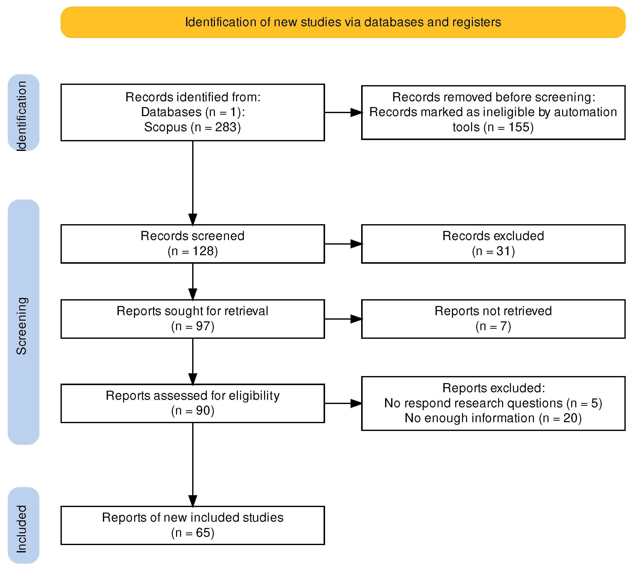
2.1. PRISMA Framework
2.2. Method’s Main Elements
3. Experimental Studies—Critical Aspects in CC Design
3.1. Cold Start
3.2. Substrate Design and Interaction with the Exhaust System
3.3. Catalyst Material
3.4. Oxygen Storage Capacity
3.5. Catalyst Deactivation
4. Numerical Research to Improve CC Knowledge
- Equations or set of coupled equations to solve: Some authors focused on a specific phenomenon, such as the temperature distribution, and, therefore, solved one transport equation (heat, mass, or momentum). In contrast, other scholars solved coupled models to estimate the light-off and/or the conversion of CCs.
- Assumptions: The simplifications applied and the boundary conditions considered, as well as the methods used to determine the required equation coefficients.
- Temporal and spatial discretization: Compared to static models, dynamic models include temporal discretization. Spatial discretization is usually applied to the length of a CC (1D models) or a longitudinal section of a CC (2D models).
- System parameters and computed responses: Among the most studied parameters are the geometry of the CC, A/F flow rate, and engine operating conditions. The responses computed are temperature, conversion efficiency, and drop pressure, among others.

| Cold Start | Conversion | Flow Distribution | Other Topics | |
|---|---|---|---|---|
| Modeled | Exhaust system with SAI (LGPi engine) [25]; Model for cold-start control [67]; Transient performance of CCs [66] | Conversion in TWCs; Oxygen Storage [56,69,71]; Conversion in TWCs [70,73]; Performance of CCs [68]; Exhaust system (SI 4-cylinder engine) [72]; Oxidation of VOCs [74] | Turbulence [79,80,81]; Pressure drop [10,82]; Flow distribution [75,76,77,78]; Flow and temperature distribution [38] | CC mass transfer [83]; TWC temperature for CC control [84]; Temperature distribution in the exhaust system [85]; Influence of engine misfiring on thermal behavior of CC [86] |
| Energy Eq. | [25,66,67] | [56,68,69,70,71,72,73,74] | [38] | [84,85,86] |
| Mass Eq. | [25,66] | [56,68,69,70,71,72,73,74] | [10,38,76,77,78,79,80,81,82] | [83,86] |
| Moment Eq. | - | [72] | [10,38,76,77,78,79,80,81,82] | |
| Chemical Eq. | Kinetic (13-step reaction mechanism); Oxygen storage (9-step reaction scheme) [66]; Empirical Wiebe profiles [67]; 7-step global chemical reactions (Langmuir–Hinshelwood) [25] | Oxygen storage model [56,69,71]; Langmuir–Hinshelwood [70,72,73] | First-order kinetic [38]; CO oxidation [78] | Reduced-order exothermic reaction kinetics [84]; CO, CH, H oxidation [86] |
| Behavior | Transient [25,66] | Transient [68,69,71,72,73,74]; Quasi-Steady [56] Dynamic [70] | - | Dynamic [84]; Quasi-steady [85]; Transient [86] |
| Dimension | 1D [25] | 1D [68,69,71,72,73,74]; 2D [56,70] | 3D (Porous medium + turbulence BC after CC) [81]; 3D (Porous medium) [38,79,82]; 3D single channel [10,80] | 1D [83,85,86] |
| Scheme | Finite differences [66] | Finite differences [72] | Finite volumes | Finite differences [86] |
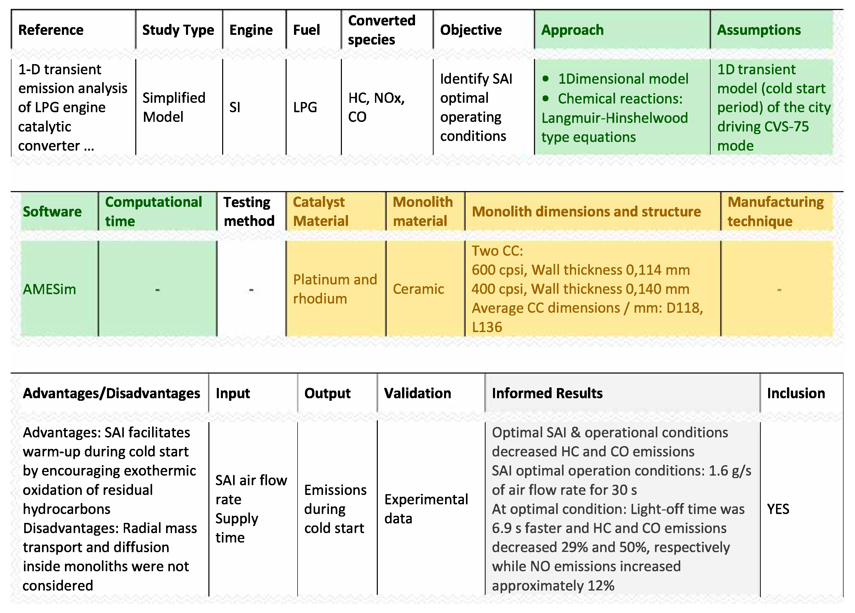
| Software | AMEsim [25] | GASDYN [72]; CTRAN [73]; Matlab [74] | ANSYS Fluent [10,79,80,81,82]; STAR CCM [76]; COMSOL Multiphysic [38]; PHOENICS and STAR-CD [77] | |
| Parameters | Engine conditions [66]; Temperature, A/F ratio [67]; SAI air-flow rate, supply time [25] | A/F ratio [69,70,72]; Engine conditions [69,73] | Length of turbulence zone Re [81]; Diffuser inlet angle [76]; Axial distance [77,78,80]; r/R [79]; Channel geometry [10] | Re · Sc [83]; Engine conditions [85]; Axial distance, misfiring, catalyst content [86] |
| Responses | Emissions [66,67]; Cumulative emissions [25,66]; Temperature [25] | Temperature [56,68,72]; Pressure [72]; Conversion [56,68,69,70,71,72,73,74] | Turbulence [79,80,81]; Pressure drop [10,76,82]; Flow uniformity index [76,78] | Sh [83]; Temperature [85,86] |
5. Conclusions
Author Contributions
Funding
Conflicts of Interest
Abbreviations
| Ag | Silver |
| AM | Additive manufacturing |
| Ar | Argon |
| BC | Boundary condition |
| CC | Catalytic converter |
| CCC | Close-coupled (light-off) catalytic converter |
| Ce | Cerium |
| CI | Compression ignition |
| CO | Carbon monoxide |
| CO | Carbon dioxide |
| cpsi | Cells per square inch |
| Cu | Copper |
| D | Catalytic converter diameter (mm) |
| Dc | Diameter of one catalytic converter cell (mm) |
| DCCS | Dynamic catalytic converter system |
| DI | Direct injection |
| DOC | Diesel oxidation catalyst |
| Porosity | |
| EGR | Exhaust gas recirculation |
| EUDC | Extra-urban driving cycle |
| F&E | Filling and emptying |
| FOS | Fractional oxidation state |
| FSE | Four-stroke engine |
| FTP | Federal test procedure |
| GDI | Gasoline direct injection |
| GSA | Geometric surface area m/m |
| HC | Hydrocarbons |
| ICE | Internal combustion engine |
| lambda number | |
| L | Catalytic converter length (mm) |
| LCA | Life-cycle assessment |
| LPG | Liquefied petroleum gas |
| MCC | Manifold catalytic converter |
| n | Engine rotational speed |
| NO | Nitrogen oxides |
| OEM | Original equipment manufacturer |
| OHV | Overhead valve |
| OSC | Oxygen storage capacity |
| PCM | Phase change material |
| Pd | Palladium |
| Pe | Peclet dimensionless number |
| Pt | Platinum |
| PtG | Power-to-gas |
| PtL | Power-to-liquid |
| QSF | Quasi-static flow |
| RAT | Rapid aging test |
| Rh | Rhodium |
| RHCC | Resistance-heated catalytic converter |
| SAI | Secondary air injection |
| Sc | Schmidt number |
| SCR | Selective catalytic reduction |
| SI | Spark ignition |
| Sh | Sherwood number |
| SSA | Specific surface area m/m |
| TCI | Turbocharged intercooled |
| TD | Turbocharged diesel |
| THC | Total hydrocarbons |
| TOSC | Total oxygen storage capacity |
| TWC | Three-way catalytic converter |
| UCC | Underbody (Underfloor) catalytic converter |
| VOC | Volatile organic compound |
| VCI | Variable-conductance isolation |
| WT | Wall thickness (mm) |
| Zn | Zinc |
References
- Lešnik, L.; Kegl, B.; Torres-Jiménez, E.; Cruz-Peragón, F. Why we should invest further in the development of internal combustion engines for road applications. Oil Gas Sci. Technol.—Rev. d’IFP Energies Nouv. 2020, 75, 56. [Google Scholar]
- Towoju, O.A.; Ishola, F.A. A case for the internal combustion engine powered vehicle. Energy Rep. 2020, 6, 315–321. [Google Scholar]
- Pregger, T.; Schiller, G.; Cebulla, F.; Dietrich, R.U.; Maier, S.; Thess, A.; Lischke, A.; Monnerie, N.; Sattler, C.; Clercq, P.L.; et al. Future fuels—Analyses of the future prospects of renewable synthetic fuels. Energies 2019, 13, 138. [Google Scholar]
- Ridjan, I.; Mathiesen, B.V.; Connolly, D.; Duić, N. The feasibility of synthetic fuels in renewable energy systems. Energy 2013, 57, 76–84. [Google Scholar]
- Ruth, J.C.; Stephanopoulos, G. Synthetic fuels: What are they and where do they come from? Curr. Opin. Biotechnol. 2023, 81, 102919. [Google Scholar]
- Styring, P.; Dowson, G.R.; Tozer, I.O. Synthetic fuels based on dimethyl ether as a future non-fossil fuel for road transport from sustainable feedstocks. Front. Energy Res. 2021, 9, 663331. [Google Scholar]
- Christensen, P.A.; Anderson, P.A.; Harper, G.D.; Lambert, S.M.; Mrozik, W.; Rajaeifar, M.A.; Wise, M.S.; Heidrich, O. Risk management over the life cycle of lithium-ion batteries in electric vehicles. Renew. Sustain. Energy Rev. 2021, 148, 111240. [Google Scholar]
- Leach, F.; Kalghatgi, G.; Stone, R.; Miles, P. The scope for improving the efficiency and environmental impact of internal combustion engines. Transp. Eng. 2020, 1, 100005. [Google Scholar]
- Kritsanaviparkporn, E.; Baena-Moreno, F.M.; Reina, T. Catalytic converters for vehicle exhaust: Fundamental aspects and technology overview for newcomers to the field. Chemistry 2021, 3, 630–646. [Google Scholar]
- Cornejo, I.; Nikrityuk, P.; Hayes, R.E. The influence of channel geometry on the pressure drop in automotive catalytic converters: Model development and validation. Chem. Eng. Sci. 2020, 212, 115317. [Google Scholar]
- Agarwal, D.; Singh, S.K.; Agarwal, A.K. Effect of Exhaust Gas Recirculation (EGR) on performance, emissions, deposits and durability of a constant speed compression ignition engine. Appl. Energy 2011, 88, 2900–2907. [Google Scholar]
- Kurzydym, D.; Żmudka, Z.; Perrone, D.; Klimanek, A. Experimental and numerical investigation of nitrogen oxides reduction in diesel engine selective catalytic reduction system. Fuel 2022, 313, 122971. [Google Scholar]
- Suarez-Bertoa, R.; Pechout, M.; Vojtíšek, M.; Astorga, C. Regulated and non-regulated emissions from Euro 6 diesel, gasoline and CNG vehicles under real-world driving conditions. Atmosphere 2020, 11, 204. [Google Scholar]
- Nishikawa-Pacher, A. Research questions with PICO: A universal mnemonic. Publications 2022, 10, 21. [Google Scholar] [CrossRef]
- Grant, M.J.; Booth, A. A typology of reviews: An analysis of 14 review types and associated methodologies. Health Inf. Libr. J. 2009, 26, 91–108. [Google Scholar]
- Higgins, J.; Thomas, J.; Chandler, J.; Cumpston, M.; Li, T.; Page, M.; Welch, V. (Eds.) Chapter I: Introduction. In Cochrane Handbook for Systematic Reviews of Interventions Version 6.3; Cochrane: London, UK, 2022; Available online: https://www.training.cochrane.org/handbook (accessed on 24 July 2023).
- Page, M.J.; McKenzie, J.E.; Bossuyt, P.M.; Boutron, I.; Hoffmann, T.C.; Mulrow, C.D.; Shamseer, L.; Tetzlaff, J.M.; Akl, E.A.; Brennan, S.E.; et al. The PRISMA 2020 statement: An updated guideline for reporting systematic reviews. Int. J. Surg. 2021, 88, 105906. [Google Scholar]
- Page, M.J.; Moher, D.; Bossuyt, P.M.; Boutron, I.; Hoffmann, T.C.; Mulrow, C.D.; Shamseer, L.; Tetzlaff, J.M.; Akl, E.A.; Brennan, S.E.; et al. PRISMA 2020 explanation and elaboration: Updated guidance and exemplars for reporting systematic reviews. BMJ 2021, 372, n160. [Google Scholar]
- Elsevier. Scopus: Access and Use Support Center. What Does “Relevance” Mean in Scopus? Available online: https://service.elsevier.com/app/answers/detail/a_id/14182/supporthub/scopus/ (accessed on 24 July 2023).
- Haddaway, N.R.; Page, M.J.; Pritchard, C.C.; McGuinness, L.A. PRISMA2020: An R package and Shiny app for producing PRISMA 2020-compliant flow diagrams, with interactivity for optimised digital transparency and Open Synthesis. Campbell Syst. Rev. 2022, 18, e1230. [Google Scholar]
- Mahadevan, G.; Subramanian, S. Experimental Investigation of Cold Start Emission Using Dynamic Catalytic Converter with Pre-Catalyst and Hot Air Injector on a Multi Cylinder Spark Ignition Engine; Technical Report, SAE Technical Paper; SAE International: Warrendale, PA, USA, 2017. [Google Scholar]
- Burch, S.D.; Potter, T.F.; Keyser, M.A.; Brady, M.J.; Michaels, K.F. Reducing cold-start emissions by catalytic converter thermal management. SAE Trans. 1995, 104, 348–353. [Google Scholar]
- Bhaskar, K.; Sassykova, L.; Prabhahar, M.; Percis, E.S.; Nalini, A.; Jenish, T.; Jayarajan, J.; Jayabalakrishnan, D.; Sendilvelan, S.; Krishnamoorthi, S. Resistance Heated Catalytic Converter (RHCC) with copper oxide catalyst for reducing HC/CO emission from automobile. Mater. Today Proc. 2021, 45, 5868–5872. [Google Scholar]
- Heck, R.; Hu, Z.; Smaling, R.; Amundsen, A.; Bourke, M. Close coupled catalyst system design and ULEV performance after 1050 C aging. SAE Trans. 1995, 104, 1217–1222. [Google Scholar]
- Yun, J. 1-D transient emission analysis of LPG engine catalytic converter with secondary air injection during cold start period of CVS-75 mode. Int. J. Automot. Technol. 2013, 14, 343–353. [Google Scholar] [CrossRef]
- Kovacev, N.; Doustdar, O.; Li, S.; Tsolakis, A.; Herreros, J.M.; Essa, K. The synergy between substrate architecture of 3D-printed catalytic converters and hydrogen for low-temperature aftertreatment systems. Chem. Eng. Sci. 2023, 269, 118490. [Google Scholar] [CrossRef]
- Lee, S.; Bae, C.; Lee, Y.; Han, T. Effects of engine operating conditions on catalytic converter temperature in an SI engine. SAE Trans. 2002, 111, 637–646. [Google Scholar]
- Young, K.; Jones, R.; Hamley, A.; Stoddard, J.; Foust, T.; Puzinauskas, P.; Yoon, H.S. Development of a catalytic converter cool-down model to investigate intermittent engine operation in HEVs. SAE Int. J. Altern. Powertrains 2018, 7, 139–154. [Google Scholar] [CrossRef]
- Kašpar, J.; Fornasiero, P.; Hickey, N. Automotive catalytic converters: Current status and some perspectives. Catal. Today 2003, 77, 419–449. [Google Scholar] [CrossRef]
- Farrauto, R.J.; Heck, R.M. Catalytic converters: State of the art and perspectives. Catal. Today 1999, 51, 351–360. [Google Scholar] [CrossRef]
- Santos, H.; Costa, M. Evaluation of the conversion efficiency of ceramic and metallic three way catalytic converters. Energy Convers. Manag. 2008, 49, 291–300. [Google Scholar] [CrossRef]
- Mahyon, N.I.; Li, T.; Martinez-Botas, R.; Wu, Z.; Li, K. A new hollow fibre catalytic converter design for sustainable automotive emissions control. Catal. Commun. 2019, 120, 86–90. [Google Scholar] [CrossRef]
- Gambarotta, A.; Papetti, V.; Dimopoulos Eggenschwiler, P. Analysis of the Effects of Catalytic Converter on Automotive Engines Performance through Real-Time Simulation Models. Front. Mech. Eng. 2019, 5, 48. [Google Scholar] [CrossRef]
- Srinivasa Chalapathi, K. Development of a Cost Effective Catalytic Converter for Diesel Automobiles. Int. J. Recent Technol. Eng. 2019, 8, 2989. [Google Scholar] [CrossRef]
- Stroom, P.D.; Merry, R.P.; Gulati, S.T. Systems Approach to Packaging Design for Automotive Catalytic Converters; Technical Report, SAE Technical Paper; SAE International: Warrendale, PA, USA, 1990. [Google Scholar]
- Mohiuddin, A.; Nurhafez, M. Experimental analysis and comparison of performance characteristics of catalytic converters including simulation. Int. J. Mech. Mater. Eng. 2007, 2, 1–7. [Google Scholar]
- Lapisa, R.; Halim, A.; Sugiarto, T.; Arwizet, K.; Martias, M.; Maksum, H.; Krismadinata, K.; Ambiyar, A. Effect of geometric parameters on the performance of motorcycle catalytic converters. Proc. J. Phys. Conf. Ser. 2020, 1469, 012176. [Google Scholar] [CrossRef]
- Hayes, R.E.; Fadic, A.; Mmbaga, J.; Najafi, A. CFD modelling of the automotive catalytic converter. Catal. Today 2012, 188, 94–105. [Google Scholar] [CrossRef]
- Brück, R.; Diewald, R.; Hirth, P.; Kaiser, F.W. Design criteria for metallic substrates for catalytic converters. SAE Trans. 1995, 104, 552–561. [Google Scholar]
- Yang, X.; Zuo, Q.; Chen, W.; Guan, Q.; Shen, Z.; Li, Q.; Xie, Y. Improvement of flow field uniformity and temperature field in gasoline engine catalytic converter. Appl. Therm. Eng. 2023, 230, 120792. [Google Scholar] [CrossRef]
- Bonet, F.; Grugeon, S.; Urbina, R.H.; Tekaia-Elhsissen, K.; Tarascon, J.M. In situ deposition of silver and palladium nanoparticles prepared by the polyol process, and their performance as catalytic converters of automobile exhaust gases. Solid State Sci. 2002, 4, 665–670. [Google Scholar] [CrossRef]
- Hayes, R.; Mukadi, L.; Votsmeier, M.; Gieshoff, J. Three-way catalytic converter modelling with detailed kinetics and washcoat diffusion. Top. Catal. 2004, 30, 411–415. [Google Scholar] [CrossRef]
- Dey, S.; Dhal, G.C. Controlling carbon monoxide emissions from automobile vehicle exhaust using copper oxide catalysts in a catalytic converter. Mater. Today Chem. 2020, 17, 100282. [Google Scholar] [CrossRef]
- Venkatesan, S.; Shubham, D.; Karan, B.; Goud, K.; Lakshmana, G.; Pavan, K. IC Engine emission reduction by copper oxide catalytic converter. IOP Conf. Ser. Mater. Sci. Eng. 2017, 197, 012026. [Google Scholar] [CrossRef]
- Chafidz, A.; MegawChafidz2018ati, M.; Widyastuti, C.; Augustia, V.; Nisa, K.; Ratnaningrum. Application of copper-zinc metal as a catalytic converter in the motorcycle muffler to reduce the exhaust emissions. IOP Conf. Ser. Earth Environ. Sci. 2018, 167, 012014. [Google Scholar] [CrossRef]
- Warju; Harto, S.; Soenarto. The Performance of Chrome-Coated Copper as Metallic Catalytic Converter to Reduce Exhaust Gas Emissions from Spark-Ignition Engine. IOP Conf. Ser. Mater. Sci. Eng. 2018, 288, 012151. [Google Scholar] [CrossRef]
- Patel, K.D.; Subedar, D.; Patel, F. Design and development of automotive catalytic converter using non-nobel catalyst for the reduction of exhaust emission: A review. Mater. Today Proc. 2022, 57, 2465–2472. [Google Scholar] [CrossRef]
- Keav, S.; Matam, S.K.; Ferri, D.; Weidenkaff, A. Structured perovskite-based catalysts and their application as three-way catalytic converters—A review. Catalysts 2014, 4, 226–255. [Google Scholar] [CrossRef]
- Pandiaraj, S.; Subbaiyan, D.; Ayyasamy, T.; Nagarajan, S. Design, Development and Analysis of Mullite Catalytic Converter for CI Engines; Technical Report, SAE Technical Paper; SAE International: Warrendale, PA, USA, 2019. [Google Scholar]
- Kumar, J.S.; Bapu, B.R.R.; Sivasaravanan, S.; Prabhu, M.; Kumar, S.M.; Abubacker, M.A. Experimental studies on emission reduction in a DI diesel engine by using a nano catalyst coated catalytic converter. Int. J. Ambient. Energy 2022, 43, 1241–1247. [Google Scholar] [CrossRef]
- Karthe, M.; Prasanna, S.C. The Mixture of Alkaline Earth Metal and Zirconium Oxide as a Catalyst in Catalytic Converter. Pak. J. Biotechnol. 2017, 168–171. [Google Scholar]
- Ghofur, A.; Soemarno; Hadi, A.; Putra, M.D. Potential fly ash waste as catalytic converter for reduction of HC and CO emissions. Sustain. Environ. Res. 2018, 28, 357–362. [Google Scholar] [CrossRef]
- Subramanian, P.; Gnanasikamani, B. Study of 4A and 5A zeolite as a catalyst material in a catalytic converter for NO emission reduction in a CI engine. Environ. Sci. Pollut. Res. 2023, 30, 41726–41740. [Google Scholar] [CrossRef]
- Lie, A.; Hoebink, J.; Marin, G. The effects of oscillatory feeding of CO and O2 on the performance of a monolithic catalytic converter of automobile exhaust gas: A modelling study. Chem. Eng. J. Biochem. Eng. J. 1993, 53, 47–54. [Google Scholar] [CrossRef]
- Li, P.; Chen, X.; Li, Y.; Schwank, J.W. A review on oxygen storage capacity of CeO2-based materials: Influence factors, measurement techniques, and applications in reactions related to catalytic automotive emissions control. Catal. Today 2019, 327, 90–115. [Google Scholar] [CrossRef]
- Koltsakis, G.; Konstantinidis, P.; Stamatelos, A. Development and application range of mathematical models for 3-way catalytic converters. Appl. Catal. B Environ. 1997, 12, 161–191. [Google Scholar] [CrossRef]
- Ohsawa, K.; Baba, N.; Kojima, S.; Matsunaga, S.; Ito, T. Numerical prediction of transient conversion characteristics in a three-way catalytic converter. SAE Trans. 1998, 107, 1359–1368. [Google Scholar]
- Zhang, Y.; Cheng, W.K. Fuel Sulfur and Aging Effects on the Oxygen Storage Capacity in Three-Way Catalytic Converters; Technical Report, SAE Technical Paper; SAE International: Warrendale, PA, USA, 2003. [Google Scholar]
- Khosh, A.; Tavasoli, A.; Mortazavi, Y.; Hosseini, M. Improving catalytic converter performance by controlling the structural and redox properties of Zr-doped CeO2 nanorods supported Pd catalysts. Res. Chem. Intermed. 2018, 44, 7753–7767. [Google Scholar] [CrossRef]
- Theis, J.R. Catalytic converter diagnosis using the catalyst exotherm. SAE Trans. 1994, 103, 1910–1924. [Google Scholar]
- Beck, D.D.; Sommers, J.W.; DiMaggio, C.L. Axial characterization of catalytic activity in close-coupled lightoff and underfloor catalytic converters. Appl. Catal. B Environ. 1997, 11, 257–272. [Google Scholar] [CrossRef]
- Poulopoulos, S.; Philippopoulos, C. MTBE, methane, ethylene and regulated exhaust emissions from vehicles with deactivated catalytic converters. Atmos. Environ. 2004, 38, 4495–4500. [Google Scholar] [CrossRef]
- Mc Grane, L.; Douglas, R.; Irwin, K.; Stewart, J.; Woods, A.; Muehlstaedt, F. A Study of the Effect of Light-Off Temperatures and Light-Off Curve Shape on the Cumulative Emissions Performance of 3-Way Catalytic Converters; Technical Report, SAE Technical Paper; SAE International: Warrendale, PA, USA, 2021. [Google Scholar]
- Maricq, M.M.; Chase, R.E.; Xu, N.; Laing, P.M. The effects of the catalytic converter and fuel sulfur level on motor vehicle particulate matter emissions: Light duty diesel vehicles. Environ. Sci. Technol. 2002, 36, 283–289. [Google Scholar] [CrossRef]
- Moldovan, M.; Palacios, M.; Gomez, M.; Morrison, G.; Rauch, S.; McLeod, C.; Ma, R.; Caroli, S.; Alimonti, A.; Petrucci, F.; et al. Environmental risk of particulate and soluble platinum group elements released from gasoline and diesel engine catalytic converters. Sci. Total Environ. 2002, 296, 199–208. [Google Scholar] [CrossRef]
- Shen, H.; Shamim, T.; Sengupta, S. An Investigation of Catalytic Converter Performances during Cold Starts; Technical Report, SAE Technical Paper; SAE International: Warrendale, PA, USA, 1999. [Google Scholar]
- Sanketi, P.R.; Hedrick, J.K.; Kaga, T. A simplified catalytic converter model for automotive coldstart control applications. In Proceedings of the ASME International Mechanical Engineering Congress and Exposition, Orlando, FL, USA, 5–11 November 2005; Volume 42169, pp. 447–452. [Google Scholar]
- Psyllos, A.; Philippopoulos, C. Modelling of monolithic catalytic converters used in automotive pollution control. Appl. Math. Model. 1992, 16, 484–490. [Google Scholar] [CrossRef]
- Aimard, F.; Li, S.; Sorine, M. Mathematical modeling of automotive three-way catalytic converters with oxygen storage capacity. Control Eng. Pract. 1996, 4, 1119–1124. [Google Scholar] [CrossRef]
- Koltsakis, G.C.; Stamatelos, A.M. Modeling dynamic phenomena in 3-way catalytic converters. Chem. Eng. Sci. 1999, 54, 4567–4578. [Google Scholar] [CrossRef]
- Kumar, P.; Makki, I.; Kerns, J.; Grigoriadis, K.; Franchek, M.; Balakotaiah, V. A low-dimensional model for describing the oxygen storage capacity and transient behavior of a three-way catalytic converter. Chem. Eng. Sci. 2012, 73, 373–387. [Google Scholar] [CrossRef]
- Onorati, A.; D’Errico, G.; Ferrari, G. 1D fluid dynamic modeling of unsteady reacting flows in the exhaust system with catalytic converter for SI engines. SAE Trans. 2000, 109, 89–103. [Google Scholar]
- Pontikakis, G.; Stamatelos, A. Identification of catalytic converter kinetic model using a genetic algorithm approach. Proc. Inst. Mech. Eng. Part D J. Automob. Eng. 2004, 218, 1455–1472. [Google Scholar] [CrossRef]
- Bedi, U.; Chauhan, S. Mathematical modeling of automotive catalytic converter for catalytic combustion of the volatile organic compound (VOC) methane. J. Phys. Conf. Ser. 2020, 1706, 012035. [Google Scholar] [CrossRef]
- Jeong, S.; Kim, T. CFD Investigation of the 3-Dimensional Unsteady Flow in the Catalytic Converter; SAE Paper 971025; SAE International: Warrendale, PA, USA, 1997. [Google Scholar]
- Khalil, S.; Pathan, K.; Ilahi, Z.; Marlpalle, B.; Khan, S. An Investigation of Three-Way Catalytic Converter for Various Inlet Cone Angles Using CFD. CFD Lett. 2020, 12, 76–90. [Google Scholar] [CrossRef]
- Martin, A.; Will, N.; Bordet, A.; Cornet, P.; Gondoin, C.; Mouton, X. Effect of flow distribution on emissions performance of catalytic converters. SAE Trans. 1998, 107, 384–390. [Google Scholar]
- Sun, S.P.; Huang, Z.; Qiao, X.Q.; Lin, H.; Chen, J.H.; Su, Q.Y. Numerical simulation of reactive flow in dual-substrate catalytic converter. Trans. CSICE 2013, 31, 461–466. [Google Scholar]
- Cornejo, I.; Nikrityuk, P.; Hayes, R.E. Multiscale RANS-based modeling of the turbulence decay inside of an automotive catalytic converter. Chem. Eng. Sci. 2018, 175, 377–386. [Google Scholar] [CrossRef]
- Cornejo, I.; Nikrityuk, P.; Hayes, R.E. Turbulence generation after a monolith in automotive catalytic converters. Chem. Eng. Sci. 2018, 187, 107–116. [Google Scholar] [CrossRef]
- Cornejo, I.; Hayes, R.E.; Nikrityuk, P. A new approach for the modeling of turbulent flows in automotive catalytic converters. Chem. Eng. Res. Des. 2018, 140, 308–319. [Google Scholar] [CrossRef]
- Cornejo, I.; Nikrityuk, P.; Hayes, R.E. Pressure correction for automotive catalytic converters: A multi-zone permeability approach. Chem. Eng. Res. Des. 2019, 147, 232–243. [Google Scholar] [CrossRef]
- Santos, H.; Costa, M. Analysis of the mass transfer controlled regime in automotive catalytic converters. Int. J. Heat Mass Transf. 2008, 51, 41–51. [Google Scholar] [CrossRef]
- Shah, D.; Premchand, K.; Pedro, D. Control Oriented Physics Based Three-Way Catalytic Converter Temperature Estimation Model for Real Time Controllers; Technical Report, SAE Technical Paper; SAE International: Warrendale, PA, USA, 2020. [Google Scholar]
- Shayler, P.J.; Hayden, D.; Ma, T. Exhaust system heat transfer and catalytic converter performance. SAE Trans. 1999, 108, 213–228. [Google Scholar]
- Oh, S.H. Thermal response of monolithic catalytic converters during sustained engine misfiring: A computational study. SAE Trans. 1988, 97, 603–610. [Google Scholar]
| Ref. | Test Bench | Fuel | Species | Catalyst Mat. | Monolith Mat. | Monolith Dimensions and Structure | Operating Regime or Synthetic Flow |
|---|---|---|---|---|---|---|---|
| [21] | SI, 4-cylinder, Izusu | - | CO, HC | - | - | - Two pre-catalysts: 20% and 40% volume of the main CC + main CC | Cold start |
| [22] | Chrysler Dodge Neon 2.0 L, 4-cylinder | - | CO, HC, NO | Nearly-fresh Pd, Loading 10.6 g/L | Cordierite | Two monoliths: D 90, L 152, 400 cpsi | FTP |
| [23] | Ambassador, SI, 4-cylinder | - | CO, HC | RHCC: Copper oxide (270 cm) | RHCC: Metal | RHCC: fine-meshed stainless-steel substrate; Primary CC | 1750 rpm under no load (20 s after cold start). The required load is applied at the same speed. |
| [25] | SI | LPG | CO, HC, NO | Pt/Rh | Ceramic | MCC: 600 cpsi, WT 0.114; UCC: 400 cpsi, WT 0.140. Both CCs: D 118, L 136 | Cold-start period in CVS-75 mode |
| [26] | CI, Diesel, 1-cylinder | Ultra-low-sulfur diesel | CO, HC, NO | Catalytic carrier: gamma alumina Precious metal: Pd (2.5 wt%) | AlO photopolymerizable ceramic slurry | Three substrates: - Diamond cell (similar to 400 cpsi); - Elongated diamond (similar to 400 cpsi); - Honeycomb (baseline) 400 cpsi. | One stationary condition representing low loads |
| [27] | SI, 1.0 L, 4-cylinder | - | - | - | - | CCC: meets Euro 3; UCC | From no load to full load conditions (1500–4000 rpm) |
| [28] | ICE hybrid electric, 2016 Chevrolet | E85 gasoline | CO, HC, NO | - | Cordierite | 1600 cpsi; oval (mm): 76.2 × 60.33, L 101.6, WT 0.1 | US06 City drive cycle |
| [32] | Reactor | - | CO | Pd, 0.7 wt% | Micro-structured alumina hollow fibers | L 50; GSA: 40 (equivalent to 750 cpsi) | Preheated flow: 50 mL min air; 50 mL min (10% CO in 90% Ar) |
| [33] | TD, 1600 cm, 4 in-line cylinders | - | CO, HC | - | Cordierite; Foams: AlO | Honeycomb: = 63%, Dc = 1, SSA = 2700, 400 cpsi Open cell foam and Kelvin cell structures: = 73%, Dc = 2, SSA = 1000 All CC: L150, D80 | Simulation: EUDC Validation: steady-state operating conditions by the OEM |
| [34] | In-line OHV, CI, FSE; Swaraj Mazda Minibus | - | CO, HC | 2 types: CeO; ZnO | 3 types: - Marble clay; - Stainless steel; - Copper sheets. | Several typologies: - Balls; - Perforated disks; - Rolled sheets. | Idling condition (with and without each CC) |
| [35] | SI | - | - | - | Cordierite ceramic | Monolith contours: round, oval or elliptic, triangular, and wide oval or racetrack; Standard monolith: 400 cpsi, WT 0.0068 | - |
| [36] | SI, 4-cylinders, Proton | - | CO, HC, NO; TWC | Pd, Rh and Pt Pd > Rh > Pt | Cordierite | Two honeycomb UCC: - 400 and 600 cpsi; - Hydraulic diameter: 1.14 and 0.98 mm; - Designed for PROTON Wira 1.3 L and FIAT Punto Selecta 1.2 L. | Steady-state analysis (cold start not included) |
| [37] | Motorbike engine | - | CO, HC | Brass; (Cu 85%, Zn 15%) | Brass plate; WT: 0.5 | Several typologies: - Set of perforated disks; - Set of folded and perforated disks; - Rolled brass plates. | 3 engine speeds: 1700 (idle), 2700, and 3700 rpm |
| [39] | 3.5 I, 4-cylinder | - | CO, HC, NO | Pt/Rh (40 g/ft) | Metallic | 5 diameters (400 cpsi): D 60, 70, 90, 105, 127; 5-cell density (D 90): 100, 200, 400, 500, 600 cpsi; 2 CC designs (400 cpsi): D 118 L 40, D 60 L 150; 2-foil WT: 0.05, 0.04 | Bag I of the FTP and in a constant high load point |
| [40] | GDI | - | NO | Pt | Metallic | Two-zone substrate WT 1.7, L 100, D 100: - Middle: High cell density (500 cpsi, SSA 2995, 72%); - Around: Low-cell density (400 cpsi, SSA 2728, 75%); Heater system placed at the monolith inlet | 6 steady-state operating conditions; (n 3000 rpm; Torque: from 11.0 Nm to 51.3 Nm) |
| [41] | Reactor | - | CO, HC, NO | 2 types: - Ag; - Pd. | 2 types: - Alumina; - Ce–Zr. | - | Synthetic gas flow similar to automobile exhaust gases |
| [44] | CI; 1-cylinder, FSE | - | CO, HC, NO, smoke | Copper oxide | Ceramic | Honeycomb Width: 150 mm; Spine: 40 mm | 0%, 25%, 50%, 75%, and 100% of maximum rated load |
| [45] | Motorbike (Honda Supra Fit 2004) | - | CO, HC | Cu-Zn | Cu-Zn | CC: L 66, D 24 inner structure: 10 tubes | n: 2000 and 2500 rpm |
| [46] | SI, Toyota Kijang LSX 1.8 series, 4-cylinder | - | CO, HC | Chrome-coated copper (CU + CR) | Metallic | Honeycomb design | Stationary tests: idle conditions from 750 rpm to 5000 rpm with a range of 250 rpm |
| [49] | CI, FSE, 1-cylinder | - | CO, HC, NO | Mullite (non-noble metal, based on material limestone) | Mullite | Perforated mullite plate | Variable engine running conditions |
| [50] | DI-Diesel, 1-cylinder, FSE, Kirloskar TV1 | Pure diesel 3 blends: diesel + biodiesel + CeO | CO, HC, NO | 2 nanocatalysts: - BaO; - MgO. | Metal | 2 CC (tubes inserted in disks) | Brake Power: from o to 3.5 kW |
| [51] | CI | - | CO, HC, NO | Blend: barium chloride + zirconium oxide | Metallic | Wire mesh: D 80, Dc 0.5 | 5 loads |
| [52] | SI, 4-cylinder, 1600 cm, FSE, TOYOTA | - | CO, HC | Fly ash (activated using sulfuric acid) | Activated Fly ash + cement (adhesive) | Several lengths (L 50, 70, 90), D 50, Dc 2 | Idle at 700, 1000, 1500, and 2000 rpm. Air injected at 0.05, 0.1, and 0.15 MPa. |
| [53] | Kirloskar 5.2 kW CI, 1-cylinder | 100% Diesel; Blend: 50% pyrolysis oil + 50% Diesel | CO, HC, NO | 2 CC, each with a different Zeolite: - First CC: ZSM 4A; - Second CC: ZSM 5A. | Zeolite + Bentonite clay + White cement + Distilled water | CC casing: D 80, L 600 Structure with circular holes | Brake power: 0, 1.32, 2.6, 3.9, and 5.2 kW (loads: 0, 4, 8, 12, and 16 kg) |
| [57] | Flow reactor | - | CO, HC, NO (Simulated) | Pt/Rh | Ceramic | Crashed ceramic substance of Pt/Rh TWC, D 15 | Inlet gas, 2 tests at 400 and 700 C: lean (CO: 2500 ppm; O: 0.325%, 0.225%); rich (7500 ppm, O: 0.175%, 0.255%) |
| [58] | Daimler-Chrysler 2.4 L, 4-cylinder | 4 fuels: Gasoline with 7, 33, 266, and 500 ppm sulfur | CO, HC, NO | Dual-brick system, 1.23 L per brick: - Front: Pd; - Rear: Pt + Rh. | Ceramic | Daimler-Chrysler 2001 Model, 2.4 L vehicles with ULEV designation | Steady-state conditions (1600 rpm and 0.5 bar intake pressure) with lambda variation |
| [59] | Reactor | - | CO, HC, NO | Pd/Zr-doped CeO, 4 Zr concentrations (5, 10, 15, and 20 mol%) | Cordierite | Honeycomb: L 20, D 10, 400 cpsi | Synthetic gas similar to gasoline exhaust gases: Propane (390 ppm) + CO (0.56 vol%) + NO (1002 ppm) + O (0.56 vol%) + CO (11 vol%) + Ar (balance), from 100 to 600 C. |
| [60] | 3.8 L sequential. Port fuel injection | - | CO, HC, NO | Pt/Rh or Pt/Pd/Rh; wash coat: alumina ceria | Ceramic | UCC: 400 cpsi; front brick 81 × 145 oval, L 152; rear brick 81 × 145 oval, L 127 | FTP |
| [61] | SI, 3.8 L | - | CO, HC, NO | CCC: Pd, 75 g/ft; UCC (two bricks): Pt 18.3, Rh 1.3 g/ft | Cordierite ceramic | CCC: D 3.66 round, L 3; UCC: front brick 3.18 × 6.68 oval, L 6; rear brick: 3.18 × 6.68 oval, L 5 | Reactor for lean and stoichiometric light-off activity and lean and stoichiometric warm-up activity at 600 C |
| [62] | IC, 4-cylinder OPEL 1.6 L | Unleaded gasoline with 11% w/w MTBE | CO, HC, MTBE, CH, Ethylene | 0.4% w/w Pt/Rh (5:1) | Ceramic (zirconia and alumina) | Made in 1997 according to Euro II: BET surface area: 8.29 m g; average pore radius: 47.40 A | Engine operating cycle range n = 1000–2500 rpm and torque = 0.1–40 lbf ft; one experiment duration = 3900 s |
| [64] | Light-duty diesel truck, 1997, 2.5 L, DI/TCI, Euro II | 2 fuels: low (4 ppm) and high (350 ppm) sulfur diesel fuel | PM | Pt-alumina zeolitic wash coat (5 mg/cm precious metal loading) | Cordierite | Two 2.5 L substrates in series with and without wash coats: - Contour: round; - 62 cells/cm; - D 144, L 152; - WT 0.0017. | Steady-state speeds (40, 70, and 70 mph) and 3% grade. Transient effects from 40 to 70 mph. Wind speed from 25 to 70 mph. Air temperature 20 C. Relative humidity from 15% to 50%. |
| [65] | SI and CI | - | - | Four CC: SI: Front brick Pt/Rh (5/1); Rear Pd/Rh (9/1); SI: Single brick Pd/Rh (9/1) with CCC; Two CI CC: Single brick Pt (1.29 g) | - | Four CC manufactured in 1998 for: - Ford Fiesta van 1.3 L (Gasoline); - Ford Fiesta van 1.1 L (Gasoline); - Seat Ibiza 1.9 L (Diesel) 2 samples. | EUDC driving cycle for light-duty vehicles |
Disclaimer/Publisher’s Note: The statements, opinions and data contained in all publications are solely those of the individual author(s) and contributor(s) and not of MDPI and/or the editor(s). MDPI and/or the editor(s) disclaim responsibility for any injury to people or property resulting from any ideas, methods, instructions or products referred to in the content. |
© 2023 by the authors. Licensee MDPI, Basel, Switzerland. This article is an open access article distributed under the terms and conditions of the Creative Commons Attribution (CC BY) license (https://creativecommons.org/licenses/by/4.0/).
Share and Cite
Robles-Lorite, L.; Dorado-Vicente, R.; Torres-Jiménez, E.; Bombek, G.; Lešnik, L. Recent Advances in the Development of Automotive Catalytic Converters: A Systematic Review. Energies 2023, 16, 6425. https://doi.org/10.3390/en16186425
Robles-Lorite L, Dorado-Vicente R, Torres-Jiménez E, Bombek G, Lešnik L. Recent Advances in the Development of Automotive Catalytic Converters: A Systematic Review. Energies. 2023; 16(18):6425. https://doi.org/10.3390/en16186425
Chicago/Turabian StyleRobles-Lorite, Laura, Rubén Dorado-Vicente, Eloísa Torres-Jiménez, Gorazd Bombek, and Luka Lešnik. 2023. "Recent Advances in the Development of Automotive Catalytic Converters: A Systematic Review" Energies 16, no. 18: 6425. https://doi.org/10.3390/en16186425