Article

Performance Simulation Model of a Radiation-Enhanced Thermal Diode Tank-Assisted Refrigeration and Air-Conditioning (RTDT-RAC) System: A Novel Cooling System

School Electrical of Mechanical Engineering, The University of Adelaide, Adelaide, SA 5005, Australia
*
Author to whom correspondence should be addressed.
Energies 2023, 16(18), 6506; https://doi.org/10.3390/en16186506
Submission received: 24 July 2023 / Revised: 6 September 2023 / Accepted: 7 September 2023 / Published: 9 September 2023
(This article belongs to the Section D: Energy Storage and Application)

Abstract

:
This paper presents a novel technology to improve the energy efficiency of refrigeration and air-conditioning (RAC) systems by applying a condenser cooling approach. The approach is based on the integration of an innovative radiation-enhanced thermal diode tank (RTDT) with a RAC system. The thermal diode tank (TDT), consisting of heat pipes and an insulated water tank, is a passive device to generate cooling water at a minimum night ambient temperature. When the radiation-enhanced heat pipe (RHP) is equipped with the TDT, it becomes an RTDT, which could theoretically lower the water temperature below the ambient temperature. In this study, a radiation-enhanced thermal diode tank (RTDT) is proposed to supply cooling water to the RAC system. Simulation models for the proposed RTDT-assisted RAC (RTDT-RAC) system are developed in order to investigate the impacts of the tank size to cooling capacity (TS/Qc) ratio, day/night ambient temperature fluctuations on the system’s coefficient of performance (COP) and the energy saving percentage (ESP). The results show that a greater day/night ambient temperature difference and a larger TS/Qc value can both enhance the COP and ESP of the RTDT-RAC system. The optimal and threshold TS/Qc values were 1 m3/kW and 0.18 m3/kW, respectively. These findings demonstrate the potential of the RTDT-RAC system to achieve significant energy savings and provide valuable insights for the design and optimization of an RTDT-RAC system.

1. Introduction

Refrigeration and air-conditioning (RAC) systems are widely used in various sectors, such as residential, commercial, and industrial applications to provide thermal comfort, preserve perishable goods, and support critical processes. As energy efficiency and environmental sustainability become increasingly important, the RAC industry faces the challenge of reducing greenhouse gas emissions, minimizing energy consumption, and optimizing system performance. Condenser cooling technology has been the subject of significant research and development efforts in recent years, aiming to enhance the overall energy efficiency, i.e., the coefficient of performance (COP), reliability, and environmental sustainability, of RAC systems. This paper, therefore, introduces an innovative condenser cooling device called radiation-enhanced thermal diode tank (RTDT). This device is expected to assist the RAC system to promote the cooling performance and achieve a higher COP.
Over the decades, condenser cooling technology has garnered considerable attention, and many relevant approaches have been developed, such as evaporative cooling, ground-sourced and water-cooling methods. This is due to the fact that, in vapour compression cooling systems, lowering the condensing temperature helps to reduce the pressure rise in the refrigerant in the compressor, saving compressor power [1]. For every 1 °C decrease in the condensing temperature, it is expected to gain a 3.23% improvement in the system COP [2]. Hajidavalloo and Eghtedari [3] built an evaporative cooler and coupled it with an air-cooled condenser, and they found at most 20% energy consumption of the system could be decreased, while the system COP was increased by about 50%. Hajidavalloo [4] also investigated the performance of evaporative cooling on the condenser of a window–air-conditioner system, and the results revealed that the proposed system could save up to 16% energy while increasing the COP by 55%. Youbi-Idrissi et al. [5] developed a numerical model of a sprayed air-cooled condenser in the RAC system, and they found that the system COP was increased by 55%. In addition, this model also found the heating capacity would increase by over 10%. The improvement in energy efficiency provided by direct evaporative coolers in air-cooled chillers was studied by Yu and Chan [6], and they were able to save more than 14% chiller power and increase the refrigeration benefits by up to 4.6%. An evaporative cooler-applied condenser was applied directly with an air-sourced heat pump and was compared with a reference air-sourced heat pump. The comparison showed that with a 72% relative humidity, nearly 9% energy, could be saved by the application of the evaporative cooler [7]. Overall, evaporative cooling has been the most widely applied and well-studied approach in condenser cooling technology, and various numerical models and experiments have validated its ability to improve the COP of RAC systems [8,9,10,11,12].
However, the ground-sourced method also plays a significant role in lowering the condensing temperature of RAC systems. Spitler and Mitchell [13] indicated that the COP of a ground-sourced heat pump (GSHP) was greatly improved when compared with a conventional air-sourced heat pump. The energy savings of GSHP systems in cold regions were demonstrated by Kharseh et al. [14], and they found that almost 20% of energy consumption could be reduced when compared to a conventional system. Furthermore, the payback time of their proposed GSHP system was 9 years. Morrone et al. [15] conducted a numerical study on the energy savings of GSHP systems under different climate conditions during a 20-year period of operation. They found that the system could achieve a seasonal COP of 4.6. Another study conducted by Luo et al. [16] revealed that the COP of the GSHP system was estimated at 3.9 under winter weather conditions. Akrouch et al. [17] proposed an advanced GSHP system, termed a shallow geothermal energy system, which was simulated for 30 years and showed an anticipated payback period of 13 years. A case study on GSHP systems under Mediterranean climate conditions was conducted by Christodoulides et al. [18], and the results showed that the highest cooling load of over 11 kW and a system COP ranging from 3.6 to 5 could be obtained. Moreover, the payback period of their GSHP system was estimated to be 20 years.
In water-sourced heat pumps (WSHPs), the water-cooling method has its great potential in energy savings for RAC systems in recent years. Maddah et al. [19] made a comprehensive study by evaluating the energy performance of a WSHP by using industrial wastewater over a GSHP and a conventional system. The COP of the WSHP system was found to be 5.104 for heating, which was selected as the best across the three systems. Wei et al. [20] also conducted an experiment to validate that their WSHP system could improve the COP and heating capacity by up to 8.1% and 22%, respectively. For RAC-cooling purposes, using water as the cooling medium to lower the condensing temperature has also been validated to effectively improve the system performance. A water/rock thermocline cold energy storage was proposed and developed by Bruch et al. [21] through experimental investigation, and they indicated that the contribution of their cold energy storage to the global cooling system could reach up to 50%. López-Zavala et al. [22] proposed a novel desalination system using water to cool the condenser, where the COP of the proposed system was over 6.5 times higher compared to that of a simple-effect absorption system. Moreover, Raveendran and Sekhar [23] experimentally studied the performance of an RAC system with a water-cooled condenser in tropical regions. The application of a residential water supply system to lower the condensing temperature was proven to reduce the energy consumption by over 20%.
Various papers in the literature have demonstrated that a performance improvement can be achieved by condenser cooling technologies in heat pump systems, for both the heating and cooling performance. The focus of this paper is to study the enhancement in cooling performance when utilizing a water-cooling approach to lower the condensing temperature of a conventional RAC system. The concept of the proposed device, a radiation-enhanced thermal diode tank (RTDT), is innovative and classified as cold energy storage. The RTDT serves as a reservoir of cooling water that is supplied to the condenser of the RAC system. By providing colder water to the condenser, the system effectively lowers the condensing temperature and this temperature reduction could enhance the system efficiency. The energy-saving potential of the RTDT-assisted RAC (RTDT-RAC) system is as yet unknown. Therefore, this paper aims to demonstrate the potential of the RTDT-RAC system to enhance the energy efficiency, compared to that of a reference air-sourced RAC system and a conventional TDT-RAC (CTDT-RAC) system without any radiative cooling benefit.

2. Performance Simulation Models

Performance simulation models based on MATLAB were developed to compare the system performance of the following RAC systems: the reference air-sourced RAC system (System 1), the fixed-speed CTDT-RAC system (System 2), the fixed-speed RTDT-RAC system (System 3), and the variable-speed RTDT-RAC system (System 4).

2.1. Physical Model

The reference RAC system, System 1, was set as a conventional air-sourced RAC system, incorporating a fixed-speed compressor, an expansion valve, an evaporator, and an air-cooled condenser, as shown in Figure 1. The condenser of the RAC system is at a high temperature (and pressure) due to the pressurization of the refrigerant by the compressor, and the heat from the condenser coils is discharged to the surrounding air with the assistance of an outdoor fan.
In System 2, a CTDT supplies cooling water to the RAC system’s condenser, so that the heat from the condenser can be dissipated directly to the water in the CTDT, instead of the surrounding air, when the RAC system runs. In this case, the system then becomes a water-sourced RAC system with a water-cooled condenser, as illustrated in Figure 2. The CTDT serves as the primary heat exchange medium in the system, which is an adiabatic water tank with heat pipes that facilitate efficient heat transfer. After absorbing the heat from the condenser, the CTDT water temperature is higher than the ambient temperature; so, the conventional heat pipe (CHP) starts to operate and transfer heat from the CTDT water to the surroundings. The heat pipe allows for an extremely fast heat transfer and tends to equalize the temperature at both ends. Therefore, during the night, the CTDT water temperature can theoretically be reduced to the lowest ambient temperature. In other words, System 2 could work at the minimum ambient temperature of the previous night [24].
As shown in Figure 3, System 3 is an RTDT-RAC system with a fixed-speed compressor, while System 4 is that with a variable-speed compressor. A variable-speed compressor is able to adjust the motor speed to pressurize the refrigerant and save energy compared with its fixed-speed equivalent; so, the input power of the compressor can be reduced. Therefore, System 4 is expected to be more energy effective than System 3.
Both System 3 and System 4 are improved versions of System 2, which replaces the CHP with the RHP. The RHP had a large flat plate facing the night sky, which could provide an effective radiative cooling benefit and thus enhance the RTDT water-cooling capabilities. Furthermore, the night sky is normally colder than the ground air, making radiative cooling highly effective. When the RTDT water is cooled to the minimum ambient temperature at night, the radiation heat transfer becomes the dominant heat transfer mechanism to further radiate heat from the water to the night sky. However, if the radiative surface of the RHP was colder than the surroundings, convective heating would occur on the radiative surface. As a result, the lowest achievable water temperature in the RTDT is reached when the convective heating and radiative cooling are in equilibrium. The RTDT takes advantage of this phenomenon by achieving water temperatures that fall below the ambient air temperature. The heat transfer dynamics between the different heat pipes and the tank water were thoroughly investigated by Wang et al. [25], and it was validated that, under identical conditions, the RTDT can generate colder tank water compared with the CTDT.

2.2. Modelling of TDT-RAC Cycles

To evaluate the performance of Systems 1–4, a mathematical model was developed using the details listed in Table 1. Some assumptions were made for the model as follows, which helped to develop a steady-state model for the initial analysis of the RTDT-RAC system.
  • There is no heat transfer through the RTDT walls;
  • The heat generated by the RAC system’s condenser is fully absorbed by the RTDT water;
  • The cooling capacity required for the conditioned room is fixed every day;
  • The evaporating temperature is set as a constant value at 10 °C;
  • In the early morning, the minimum CTDT water temperature is 2 °C higher than the night ambient temperature, whereas the minimum RTDT water temperature is 0.5 °C higher than the night ambient temperature;
  • There is no heat loss in processes 3 to 4 (via the expansion valve);
  • The temperature distributions within the CTDT and RTDT are uniform;
  • Constant ambient conditions are also assumed, such as the ambient temperature, sky temperature, and wind speed;
  • The model assumes an ideal heat transfer and neglects any losses or inefficiencies that may occur in practical scenarios;
  • A reasonable estimate for the temperature gap between the refrigerant temperature inside the condenser coils and the external (air/water) temperature around the condenser coil can range from 5 to 15 °C. In this model, the condensing temperature is either 15 °C higher than the ambient air temperature or 5 °C higher than the water temperature.
According to the system description, the mathematical models were developed as follows:

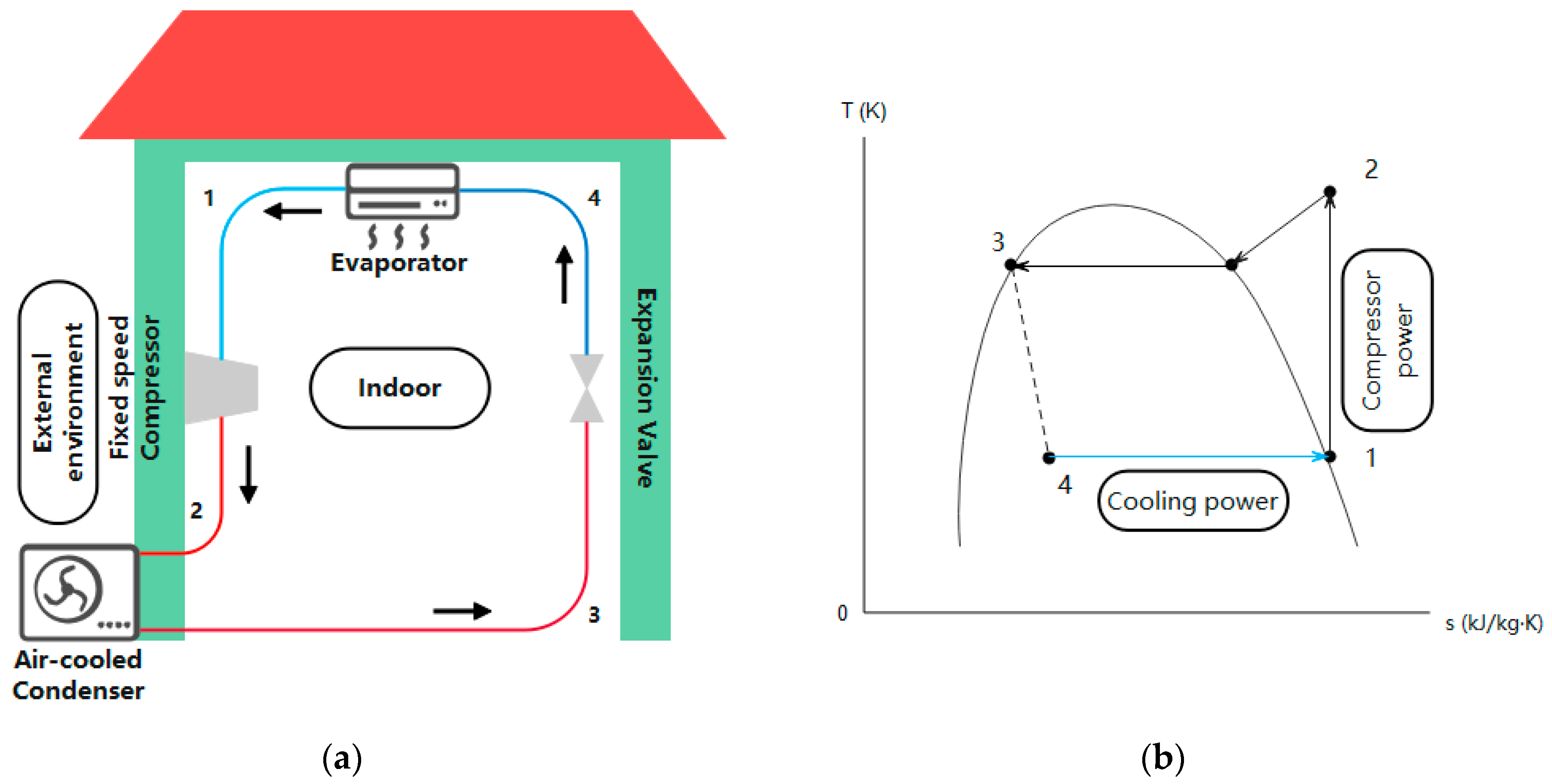
2.2.1. System 1: A Reference Air-Sourced RAC System

As shown in Figure 1, the COP in RAC systems is calculated as the ratio of cooling power to compressor power, which can be calculated in terms of specific enthalpies:
C O P s 1 = h 1 h 4   h 2 h 1  
where h1, h2, and h4 represent the specific enthalpies of the refrigerant at the compressor, condenser, and evaporator, respectively, which are set according to the corresponding refrigerant temperatures T1, T2, and T4. Referring to the temperature table of saturation properties of the specific refrigerant, when T1, T2, and T4 are found, h1, h2, and h4 can then be calculated.

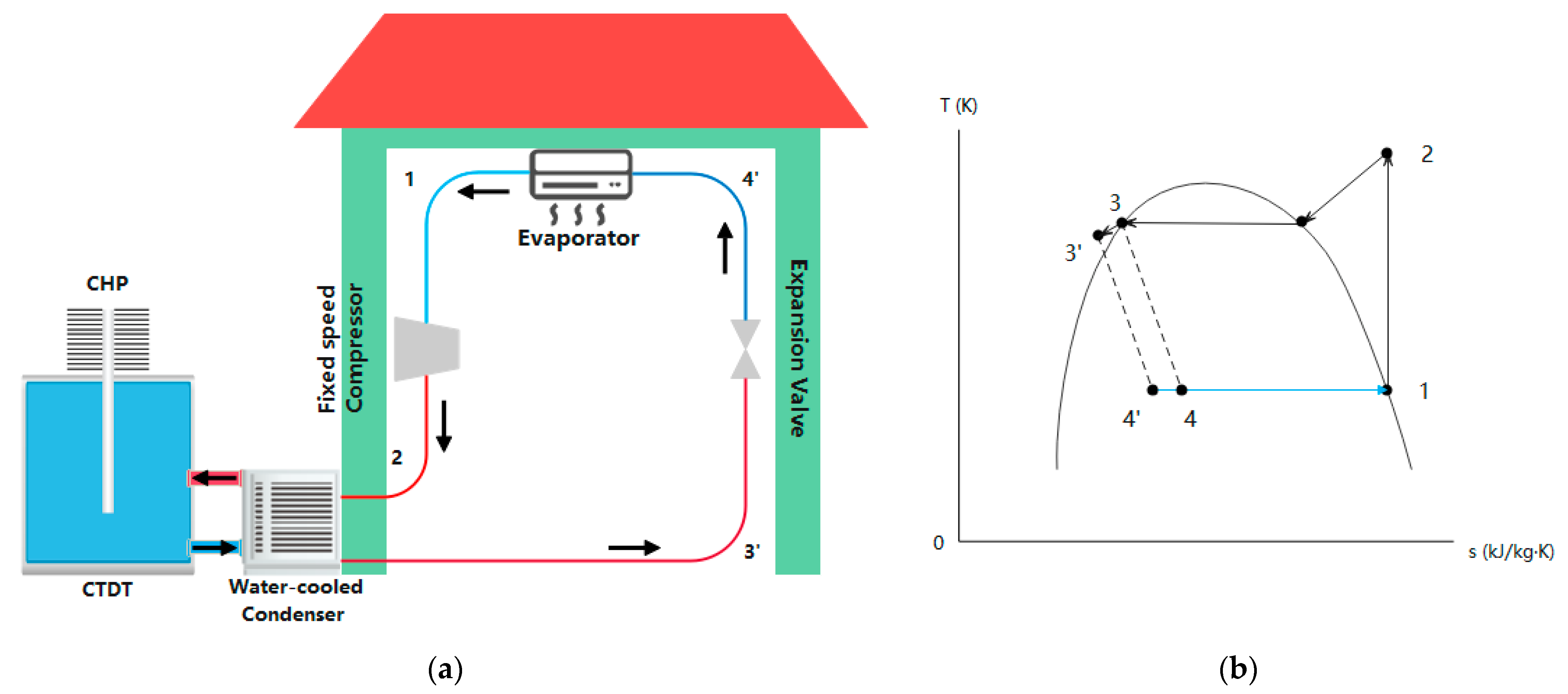
2.2.2. System 2: A Fixed-Speed CTDT-RAC System

For System 2, when the cooling water is supplied to the condenser of the RAC system, the refrigerant temperature at state 3 decreases to state 3′ (from T3 to T3′), as shown in Figure 2. Since the condenser is in direct contact with the cooling water of the CTDT, the condensing temperature T3′ depends on the CTDT water temperature.
Therefore, it is necessary to simulate the water temperature to find the COP of System 2. During the operation of the TDT-RAC system in the daytime, the ambient air temperature is higher than the TDT water temperature; so, the heat pipe is non-operational. As the heat generated from the condenser is assumed to be fully absorbed by the TDT water, it can be expressed as:
Q w a t e r = Q c o n d e n s e r
where
Q w a t e r = ρ V C P T
Q c o n d e n s e r = m ˙ h 2 h 3 t
Qwater (kJ) and Qcondenser (kJ) represent the heat transferred from the RAC system’s condenser to the TDT water; m (kg) is the water mass, Cp (kJ/kg °C) is the specific heat capacity of water; h2 and h3′ (kJ/kg) are specific enthalpies of the refrigerant at states 2 and 3′, respectively; ρ is the water density; V is the volume of TDT water; m ˙ (kg/s) is the refrigerant mass flow rate; ∆t is the time step; and ∆T is the temperature change in the TDT water. Following the correlation above, the TDT water temperature change (∆T) over a time step (∆t) is:
T = m ˙ h 2 h 3 t C P m
Eventually, the water temperature history becomes:
T w a t e r i + 1 = T w a t e r i + T i ,   i 1
where i is the sequential order of the time step. According to the assumption, the water temperature during the early morning is assumed to be 2 °C higher than the lowest night ambient temperature, which is a given input. In this case, the initial TDT water temperature, Twater1, is known as well as the h3′ of the first time step. Therefore, both ∆T1 and Twater2 can be found. Through this calculation process, the TDT water temperature history can be obtained. Assuming the condensing temperature, T3′, is 5 °C higher than the TDT water temperature, the specific enthalpies h3′ and h4′ can be found. Therefore, the COP of System 2 at the corresponding time step becomes:
C O P s 2 i = h 1 h 4 i h 2 h 1  

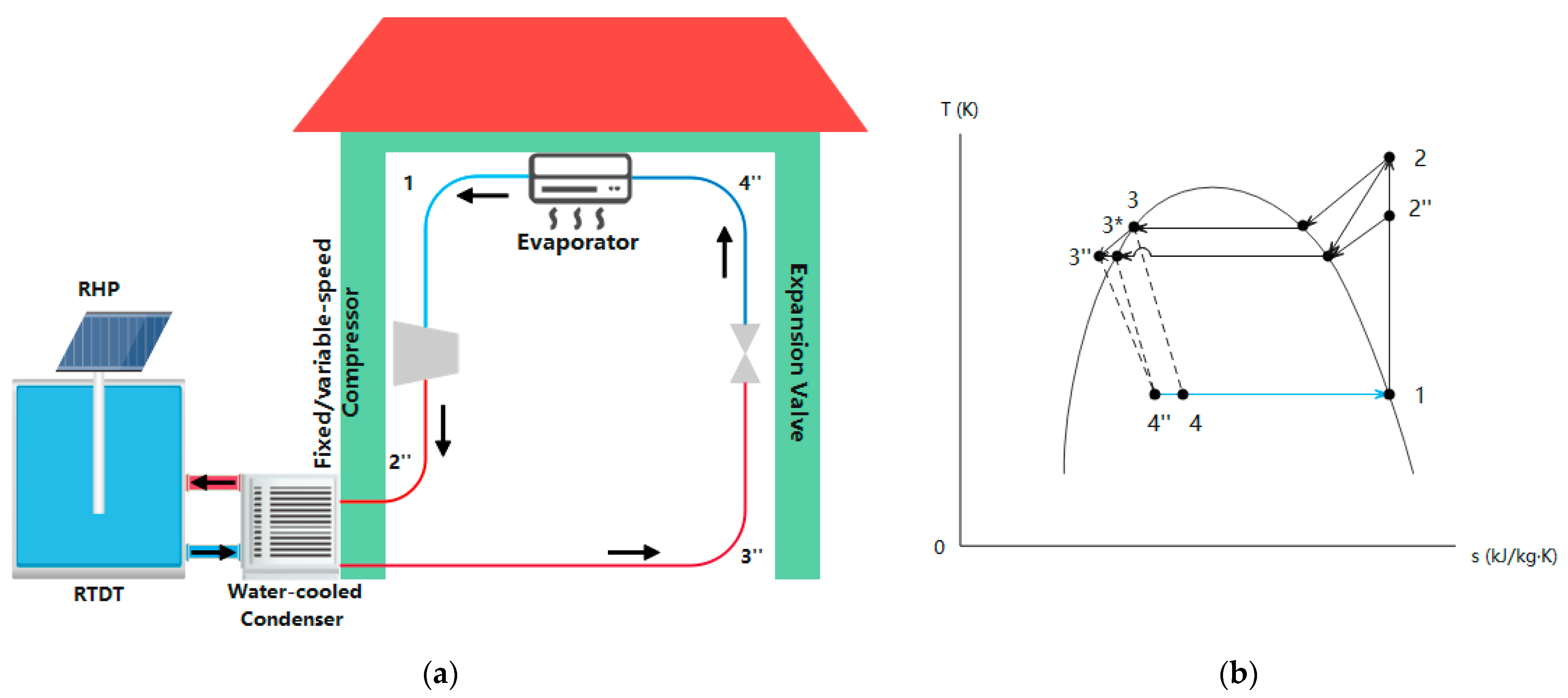
2.2.3. Systems 3 and 4: RTDT-RAC Systems

As an advanced version of System 2, System 3 could offer colder water to cool the RAC system’s condenser; so, the condensing temperature of System 3 (T3″) is lower than that of System 2 (T3′).
C O P s 3 i = h 1 h 4 i h 2 h 1  
The cooling capacity of the conditioned room is assumed to be constant. Under this condition, the variable-speed compressor continuously monitors the room temperature and cooling load. Based on this real-time information, it automatically varies its speed to deliver the exact amount of cooling needed to maintain the desired temperature in the conditioned space. Therefore, if the fixed-speed compressor is replaced by one with a variable speed, it can reduce the input work of the compressor and generate less heat. The refrigerant at the compressor can be cooled from state 2 to 2″ (from T2 to T2″). Consequently, the COP of System 4 at the corresponding time step is:
C O P s 4 i = h 1 h 4 i h 2 i h 1  
The energy savings achieved by Systems 2–4 compared to those of reference System 1 were also considered as a performance indicator. Since the cooling capacity for the conditioned room remains constant for each system throughout the day, the input energy of the compressor, Wc (kWh), corresponding to the cooling capacity can be determined:
W c j = Q ˙ R A C C O P j × t R A C
Then, the saved energy of Systems 2–4 is:
E s j = W c 1 W c j
The energy-saving percentage (ESP) for Systems 2–4 can be determined by:
E S P j = E s j W c 1 × 100 %
where the subscript j represents the system number.

3. Reference Case

A reference case was set to make initial comparisons across Systems 1–4 regarding their COP values and ESP, and the characteristics are listed in Table 2. It is noted that all systems are under the same ambient conditions and use R134a as their refrigerant.
In the reference case, all systems run 8 h per day, and their average COP values were calculated over hourly COP values for 8 h. The results of Systems 1–4 regarding their COP values and saved energy were found. In Table 3 and Figure 4, Systems 2–4 show significant improvements in their COP values compared with System 1, with values of 5.48, 5.59, and 8.97, respectively. Systems 2 and 3 both saved about 5 kWh of energy, resulting in an ESP of around 15%. On the other hand, System 4 achieved even greater energy savings, amounting to 15 kWh and a remarkable ESP of 45.59%. These results highlight the substantial energy-saving potential offered by Systems 2–4 when compared to reference System 1.

4. Sensitivity Analysis

To find the impacts of design and operational parameters on the energy efficiency of the TDT-RAC systems, a parametric analysis was conducted on the day/night ambient temperatures, tank size, and cooling capacity.

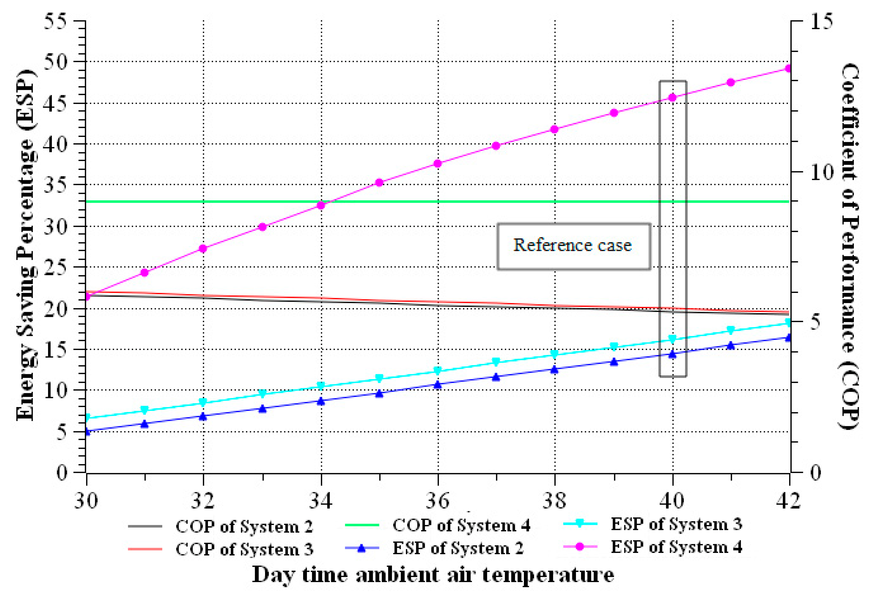
4.1. Daytime Ambient Temperature

In Figure 5, the energy-saving percentages (ESPs) of Systems 2–4 all exhibit an increasing trend as the daytime ambient air temperature rises. This observation suggests a positive correlation between the ambient temperature and the energy-saving performance of those systems. In addition, the COP values of System 2–4 are almost unchanged even though the daytime ambient temperature rose significantly. This is primarily because the increase in the ambient air temperature caused more energy consumption from the air-cooled compressor of the reference System 1, whilst it has a neglectable influence on Systems 2–4 since they are equipped with water-sourced condensers. Therefore, although it could subsequently improve the ESPs of System 2–4, their COP values are expected to change minimally. These findings underscore the sensitivity of COP and ESP to variations in daytime ambient temperatures, highlighting the potential for enhanced energy efficiency in Systems 2–4 when operating under a higher ambient temperature during the daytime.

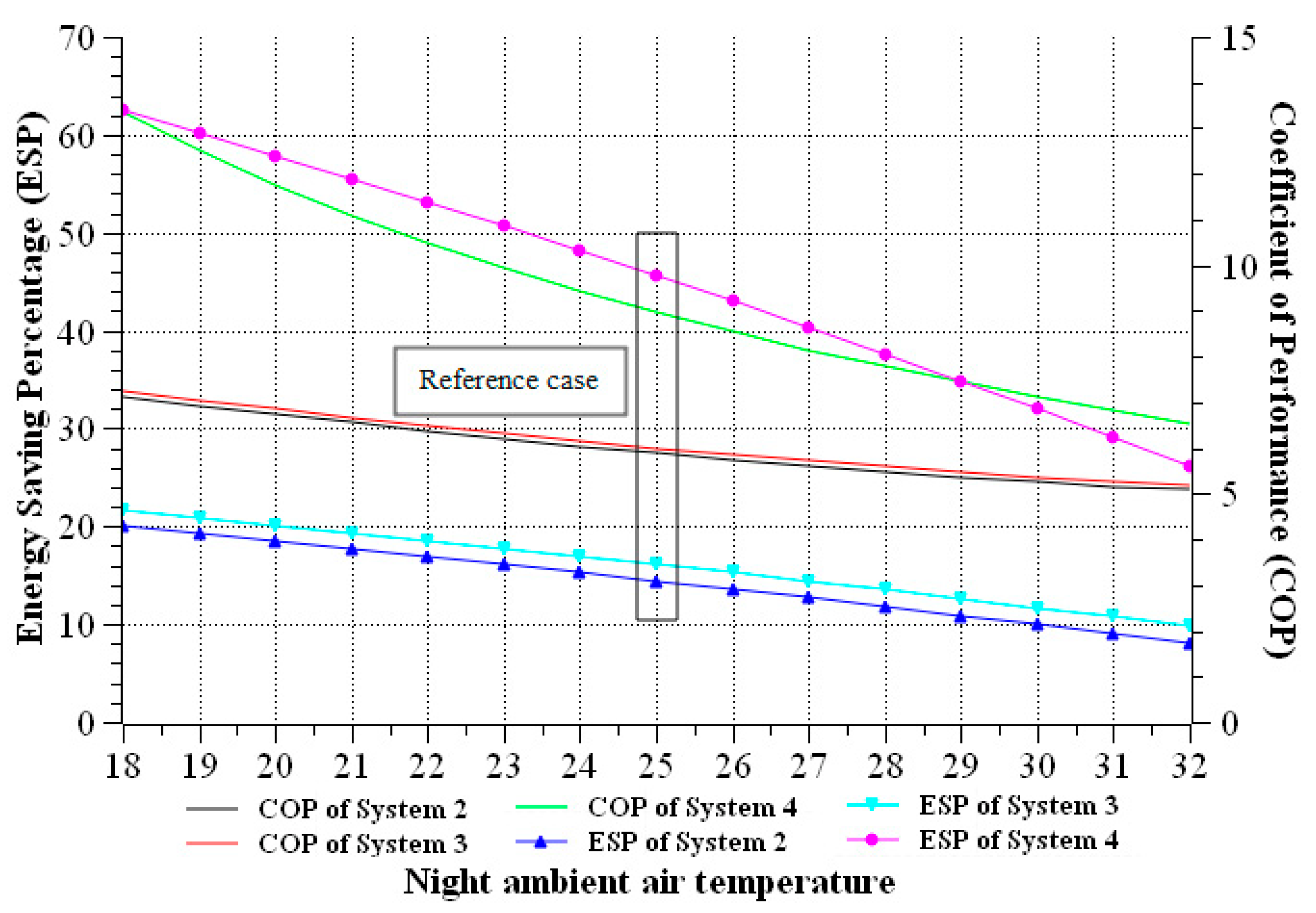
4.2. Night Ambient Temperature

In the assumptions, both CTDT and RTDT water temperatures are linearly dependent on the night ambient air temperature. Figure 6 reveals that higher night ambient air temperatures can lead to reduced COP and ESP values in Systems 2–4. When the night ambient temperature rises, the water temperatures in the TDT also increase, resulting in the condensers of Systems 2–4 operating at higher temperatures. As a consequence, Systems 2–4 experience a decrease in energy savings. In contrast, System 1, which utilizes an air-cooled condenser, remains unaffected by the night ambient temperature. This finding highlights that higher night temperatures can lead to reduced performance and efficiency in Systems 2–4.
Considering the findings in Figure 5 and Figure 6 from the perspective of the day/night ambient temperature differences, higher daytime ambient temperatures and/or lower the night ambient temperatures could lead to an effective improvement in Systems 2–4, regardless of the TDT and compressor type. Overall, maximizing the temperature differential can help to unlock the full potential of Systems 2–4.

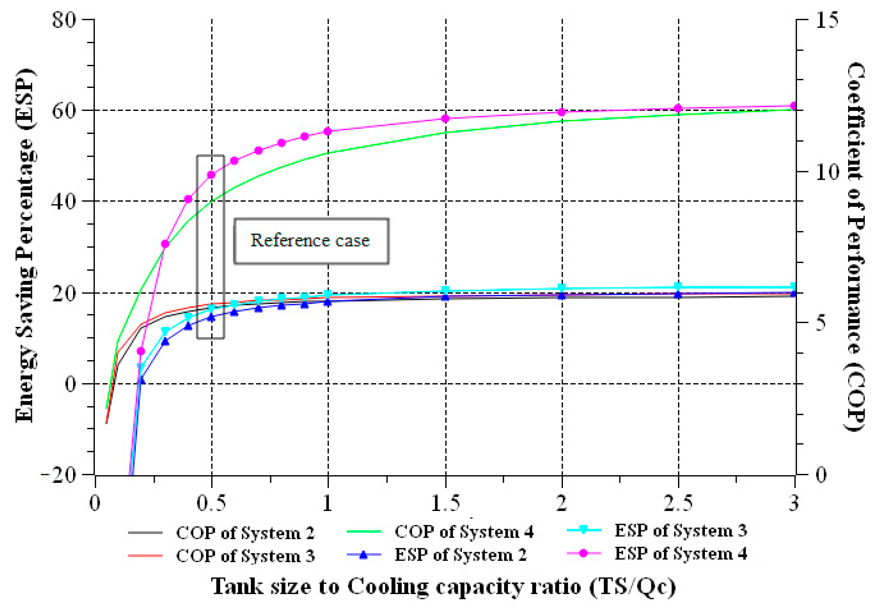
4.3. Tank Size to Cooling Capacity (TS/Qc) Ratio

The tank size to cooling capacity (TS/Qc) ratio is a coupled parameter of the tank size and cooling capacity that can significantly impact the performance of Systems 2–4. As illustrated in Figure 7, in terms of ESP, an increase in the TS/Qc value initially leads to a rapid increase in ESP for all systems. However, these increasing trends gradually diminish and eventually reach their maximal values. Notably, a threshold TS/Qc value of approximately 0.18 m3/kW is identified for Systems 2–4, above which a positive ESP can be achieved. Furthermore, to maximize the cost-effectiveness, it is recommended to adopt an optimal TS/Qc value of 1 m3/kW for Systems 2–4.
The COP curves exhibit a similar trend to the ESP curves, with rapid initial increases followed by a flattening of the curves. The COP values reach their maximum at an optimal TS/Qc value, beyond which further increases in the ratio lead to a diminishing increase rate in terms of COP enhancement.
These findings emphasize the importance of analyzing the TS/Qc value when optimizing TDT-RAC systems. Selecting an appropriate tank size relative to the cooling capacity enables the achievement of the greatest energy savings and cost-effectiveness.

5. Economic Analysis

Estimating the cost of implementing a TDT with an RAC system can vary significantly depending on the system’s size, complexity, location, and the specific components used. A general breakdown of potential cost factors includes materials, installation, and maintenance.
Generally, the larger the volume, the more materials the system consumes. This may include the heat pipe, water tank, insulation, valves, pumps, and other hardware. Based on the TDT volume, the estimated cost range for materials and components of a small TDT (0 to 5 m3) is from A$500 to A$900. A medium TDT (from 5 to 20 m3) could cost A$900 to A$3000. For a massive TDT of over 20 m3, the material cost can be up to A$6000. The estimated installation cost of the TDT (0 to 50 m3) ranges from A$500 to A$4000 [26]. In addition, maintenance costs per year, as a percentage of the initial system cost, may range from 1% to 3%. Therefore, the payback time (x) in years can be calculated as:
T D T   c o s t + I n s t a l l a t i o n   f e e + x × M a i n t e n a n c e % = E l e c t r i c i t y   r a t e × E s × 365
Taking the reference case as an example, the cost of TDT itself is about A$1600, whereas the installation fee is about A$1200, assuming that the yearly maintenance cost is 2% of the initial system cost. In South Australia, the electricity rate is about A$0.36 per kWh [27]; so, the estimated payback times of Systems 2–4 are 4.7, 4.2, and 1.4 years, respectively.

6. Conclusions

This paper proposed three TDT-RAC systems with different characteristics to simulate their energy efficiencies and demonstrate the superiority of the RTDT-RAC system over the reference RAC system. The performance simulation models of all three TDT-RAC systems under steady state provided valuable insights into their operational characteristics and energy-saving potential. Through sensitivity studies, several key findings emerged:
  • In the reference case analysis, the proposed RTDT-RAC system incorporating a variable-speed compressor demonstrated the highest energy efficiency. This configuration achieves optimal energy savings, with potential energy reductions of up to 45.59%. The fixed-speed RTDT-RAC system and the CTDT-RAC system also exhibit notable energy savings, with energy reductions of 16.11% and 14.43%, respectively. These findings prove the superior performance of the RTDT-RAC system compared to that of other systems;
  • The day/night ambient temperature difference was identified as a critical factor influencing the system performance. The results indicate that Systems 2–4, equipped with water-sourced condensers, are sensitive to changes in ambient temperatures. A higher day/night ambient temperature difference leads to an improved system performance, which also highlights the need for the careful consideration of compatibility with the prevailing environmental conditions during the system design;
  • The impact of the tank size to cooling capacity (TS/Qc) ratio on system performance was investigated. The findings reveal that the ESP and COP curves exhibit similar trends. Increasing the TS/Qc ratio initially leads to rapid improvements in energy savings and COP, but the curves eventually flatten out. An optimal TS/Qc value of 1 m3/kW was found to offer the highest cost-effectiveness and efficiency. Beyond this value, further increases in the ratio result in diminishing returns in terms of ESP and COP enhancement;
  • The analysis also identified a threshold TS/Qc value, which is approximately 0.18 m3/kW for the TDT-RAC systems to achieve positive ESPs. Below this threshold value, Systems 2–4 consume more energy than the reference system.
Overall, the findings of this study can guide the selection of system parameters and facilitate the development of sustainable and cost-effective cooling solutions in various applications.
Future research should focus on exploring additional parameters and optimization strategies to further enhance the energy-saving potential of RTDT-RAC systems. More detailed and comprehensive simulations, including the transient heat transfer process, under dynamic modes can be developed to capture the system’s behaviour with even higher accuracy. To attain an accurate dataset on the energy savings of the TDT-RAC systems, experimental validation is also necessary to be conducted. It could also include an empirical study to investigate the design and operational challenges of the TDT-RAC systems and to explore the viability of heat transfer and energy storage during daytime.

7. Patents

Eric Jing Hu has the patent “A HEAT TRANSFER ARRANGEMENT FOR IMPROVED ENERGY EFFICIENCY OF AN AIR CONDITIONING SYSTEM–A thermal ‘Diode Tank’” issued to AU 2014202998 Al.

Author Contributions

Conceptualization, E.H.; methodology, M.W.; software, M.W.; formal analysis, M.W.; investigation, M.W.; resources, M.W.; data curation, M.W. and E.H.; writing—original draft preparation, M.W.; writing—review and editing, M.W., E.H. and L.C.; supervision, E.H. and L.C.; project administration, E.H. and L.C. All authors have read and agreed to the published version of the manuscript.

Funding

This research received no external funding.

Data Availability Statement

The data presented in this study are available upon request from the corresponding author.

Acknowledgments

The authors would like to acknowledge the support, resources, and the University of Adelaide Research Scholarship provided by the University of Adelaide, which were instrumental in conducting this study.

Conflicts of Interest

The authors declare no conflict of interest.

Nomenclature

C P Specific heat capacity (kJ/kg °C)
EsSaved energy (kJ)
hSpecific enthalpy (kJ/kg)
m ˙ Mass flow rate (kg/s)
mMass (kg)
Q o u t Heat through to condenser(kJ)
Q ˙ o u t The rate of heat through to the condenser (kW)
Q ˙ R A C Cooling capacity (kW)
T a Daytime ambient temperature (°C)
T n i g h t Night ambient temperature (°C)
T r o o m Room temperature (°C)
TS/QcTank size to cooling capacity ratio
T w a t e r _ c CTDT water temperature (°C)
T w a t e r _ R RTDT water temperature (°C)
TDay and night ambient temperature difference (°C)
t R A C System daily operating time (h or s)
t System operating time interval (h or s)
V Tank size (m3)
iNumber of time step
jSystem number
W C Input energy (kJ)
Greek Symbols
ρ Density (kg/m3)
Abbreviations
CHPConvective heat pipe
COPCoefficient of performance
CTDTConvection thermal diode tank
ESPEnergy-saving percentage
GSHPGround-sourced heat pump
HTCHeat transfer capacity
RACRefrigeration and air-conditioning
RHPRadiation-enhanced heat pipe
RTDTRadiation-enhanced thermal diode tank
TDTThermal diode tank
TDT-RACThermal diode tank-assisted refrigeration and air-conditioning
WSHPWater-sourced heat pump

References

  1. Jahangeer, K.; Tay, A.A.; Islam, R. Numerical investigation of transfer coefficients of an evaporatively-cooled condenser. Appl. Therm. Eng. 2011, 31, 1655–1663. [Google Scholar] [CrossRef]
  2. Kumbhar, A.; Gulhane, N.; Pandure, S. Effect of Various Parameters on Working Condition of Chiller. Energy Procedia 2017, 109, 479–486. [Google Scholar] [CrossRef]
  3. Hajidavalloo, E.; Eghtedari, H. Performance improvement of air-cooled refrigeration system by using evaporatively cooled air condenser. Int. J. Refrig. 2010, 33, 982–988. [Google Scholar] [CrossRef]
  4. Hajidavalloo, E. Application of evaporative cooling on the condenser of window-air-conditioner. Appl. Therm. Eng. 2007, 27, 1937–1943. [Google Scholar] [CrossRef]
  5. Youbi-Idrissi, M.; Macchi-Tejeda, H.; Fournaison, L.; Guilpart, J. Numerical model of sprayed air cooled condenser coupled to refrigerating system. Energy Convers. Manag. 2007, 48, 1943–1951. [Google Scholar] [CrossRef]
  6. Yu, F.W.; Chan, K.T. Application of Direct Evaporative Coolers for Improving the Energy Efficiency of Air-Cooled Chillers. J. Sol. Energy Eng. 2005, 127, 430–433. [Google Scholar] [CrossRef]
  7. Kim, B.-J.; Jo, S.-Y.; Jeong, J.-W. Energy performance enhancement in air-source heat pump with a direct evaporative cooler-applied condenser. Case Stud. Therm. Eng. 2022, 35, 102137. [Google Scholar] [CrossRef]
  8. Ketwong, W.; Deethayat, T.; Kiatsiriroat, T. Performance enhancement of air conditioner in hot climate by condenser cooling with cool air generated by direct evaporative cooling. Case Stud. Therm. Eng. 2021, 26, 101127. [Google Scholar] [CrossRef]
  9. Pan, S.; Pei, F.; Wei, Y.; Wang, H.; Liu, J.; Zhang, X.; Li, G.; Gu, Y. Design and experimental study of a novel air conditioning system using evaporative condenser at a subway station in Beijing, China. Sustain. Cities Soc. 2018, 43, 550–562. [Google Scholar] [CrossRef]
  10. Ruiz, J.; Cutillas, C.; Martínez, P.; Kaiser, A.; Lucas, M. Experimental study on energy performance of a split air-conditioner by using variable thickness evaporative cooling pads coupled to the condenser. Appl. Therm. Eng. 2016, 105, 1041–1050. [Google Scholar] [CrossRef]
  11. Wang, T.; Sheng, C.; Nnanna, A.A. Experimental investigation of air conditioning system using evaporative cooling condenser. Energy Build. 2014, 81, 435–443. [Google Scholar] [CrossRef]
  12. Sarntichartsak, P.; Thepa, S. Modeling and experimental study on the performance of an inverter air conditioner using R-410A with evaporatively cooled condenser. Appl. Therm. Eng. 2013, 51, 597–610. [Google Scholar] [CrossRef]
  13. Spitler, J.D.; Mitchell, M.S. Advances in Ground-Source Heat Pump Systems. Surface Water Heat Pump Systems; Woodhead Publishing: Stillwater, Oklahoma, USA, 2016; Available online: https://www.sciencedirect.com/science/article/abs/pii/B978008100311400008X (accessed on 12 May 2023).
  14. Kharseh, M.; Al-Khawaja, M.; Suleiman, M.T. Potential of ground source heat pump systems in cooling-dominated environments: Residential buildings. Geothermics 2015, 57, 104–110. [Google Scholar] [CrossRef]
  15. Morrone, B.; Coppola, G.; Raucci, V. Energy and economic savings using geothermal heat pumps in different climates. Energy Convers. Manag. 2014, 88, 189–198. [Google Scholar] [CrossRef]
  16. Luo, J.; Rohn, J.; Bayer, M.; Priess, A.; Wilkmann, L.; Xiang, W. Heating and cooling performance analysis of a ground source heat pump system in Southern Germany. Geothermics 2014, 53, 57–66. [Google Scholar] [CrossRef]
  17. Akrouch, G.A.; Sánchez, M.; Briaud, J.-L. Thermal performance and economic study of an energy piles system under cooling dominated conditions. Renew. Energy 2020, 147, 2736–2747. [Google Scholar] [CrossRef]
  18. Christodoulides, P.; Aresti, L.; Florides, G. Air-conditioning of a typical house in moderate climates with Ground Source Heat Pumps and cost comparison with Air Source Heat Pumps. Appl. Therm. Eng. 2019, 158, 113772. [Google Scholar] [CrossRef]
  19. Maddah, S.; Deymi-Dashtebayaz, M.; Maddah, O. 4E analysis of thermal recovery potential of industrial wastewater in heat pumps: An invisible energy resource from the iranian casting industry sector. J. Clean. Prod. 2020, 265, 121824. [Google Scholar] [CrossRef]
  20. Wei, F.; Wang, B.; Cheng, Z.; Cui, M. Experimental research on vapor-injected water source heat pump using R1234ze(E). Appl. Therm. Eng. 2023, 229, 120595. [Google Scholar] [CrossRef]
  21. Bruch, A.; Bourdon, D.; Dumas, C.; Blaise, A.; Chouvel-Saye, A. Experimental characterization of a water/rock thermocline cold thermal energy storage for optimization of condenser cooling. J. Energy Storage 2021, 44, 103426. [Google Scholar] [CrossRef]
  22. López-Zavala, R.; Velázquez-Limón, N.; Ojeda-Benítez, S.; Nakasima-López, M.; Lara, F.; Aguilar-Jiménez, J.; Santillán-Soto, N.; Islas, S. Novel desalination system that uses product water to generate cooling through a barometric ejector-condenser. Energy 2023, 276, 127536. [Google Scholar] [CrossRef]
  23. Raveendran, P.S.; Sekhar, S.J. Experimental studies on the performance improvement of household refrigerator connected to domestic water system with a water-cooled condenser in tropical regions. Appl. Therm. Eng. 2020, 179, 115684. [Google Scholar] [CrossRef]
  24. Wang, M.; Hu, E.; Chen, L. Energy-Saving Potential of Thermal Diode Tank Assisted Refrigeration and Air-Conditioning Systems. Energies 2021, 15, 206. [Google Scholar] [CrossRef]
  25. Wang, M.; Hu, E.; Chen, L. Radiation-enhanced thermal diode tank (RTDT) for refrigeration and air-conditioning (RAC) systems. Int. J. Refrig. 2023, 146, 237–247. [Google Scholar] [CrossRef]
  26. Cost of a Rainwater Tank—Tankworld Australia. Available online: https://www.tankworld.com.au/cost-of-a-rainwater-tank/ (accessed on 10 August 2023).
  27. Average Electricity Prices in Australia per kWh—Canstar Blue. Available online: https://www.canstarblue.com.au/electricity/electricity-costs-kwh/ (accessed on 10 August 2023).
Figure 1. (a) Reference air-sourced RAC system (System 1). (b) Thermodynamic cycle (1→2→3→4→1) of System 1 with a fixed-speed compressor, where System 1 is equipped with an outdoor air-cooled condenser and the evaporator supplies cooling power to the room.
Energies 16 06506 g001
Figure 2. (a) CTDT- RAC system (System 2); (b) Thermodynamic cycle (1→2→3′→4′→1) of System 2 and cycle (1→2→3→4→1) of System 1. System 2 is equipped with a fixed-speed compressor.
Energies 16 06506 g002
Figure 3. (a) RTDT- RAC system (System 3 has a fixed-speed compressor, while System 4 has a variable-speed compressor). (b) Thermodynamic cycle (1→2→3″→4″→1) of System 3 and cycle (1→2″→3*→4″→1) of System 4.
Energies 16 06506 g003
Figure 4. Results of Systems 1–4 for the reference case.
Energies 16 06506 g004
Figure 5. Sensitivity of COP and ESP to variations in daytime ambient air temperatures (the ESPs of Systems 2–4 increase with the increase in daytime ambient air temperature).
Energies 16 06506 g005
Figure 6. Sensitivity of COP and ESP to variations in night ambient air temperatures (the ESPs of Systems 2–4 decrease if the night ambient air temperature rises).
Energies 16 06506 g006
Figure 7. Sensitivity of COP and ESP to variations in tank size to cooling capacity (TS/Qc) ratios (the COP values and ESPs of Systems 2–4 increase and tend to flatten if the TS/Qc ratio increases, and there is a threshold TS/Qc value for Systems 2–4 to achieve a positive ESP).
Energies 16 06506 g007
Table 1. Specifications of the mathematical model.
Input
Q ˙ R A C Cooling capacity for the conditioned room (kW)
TroomRoom temperature (°C)
TaDaytime ambient air temperature (°C)
TeEvaporating temperature (°C)
TnightNight ambient temperature (°C)
Twater_CCTDT water temperature (°C)
Twater_RRTDT water temperature (°C)
tTime step (hour)
tRACTotal operation time (hour)
VTank size (m3)
CPSpecific heat capacity of water (kJ/kg °C)
ρ Density of water (kg/m3)
Outputs
COPCOP for each time step
W ˙ c Compressor power
EsSaved energy
Table 2. Input parameters of the reference case.
Input
Daytime ambient air temperature, Ta (°C)40
Conditioned room temperature, Troom (°C)22
Evaporating temperature, Te (°C)10
Night ambient temperature, Tnight (°C)25
CTDT water temperature, Twater_C (°C)27 (Tnight + 2 °C)
RTDT water temperature, Twater_R (°C)25.5 (Tnight + 0.5 °C)
Tank size, V (m3)10
Water density, ρ (kg/m3)1000
RAC system cooling capacity, Q ˙ R A C (kW)20
Tank size to cooling capacity (TS/Qc) ratio0.5
RAC system daily operation duration, tRAC (hour)8 (from 9 am to 17 pm)
Table 3. Results of the reference case.
SystemsCOPDaily Wc (kWh)Daily Es (kWh)ESP
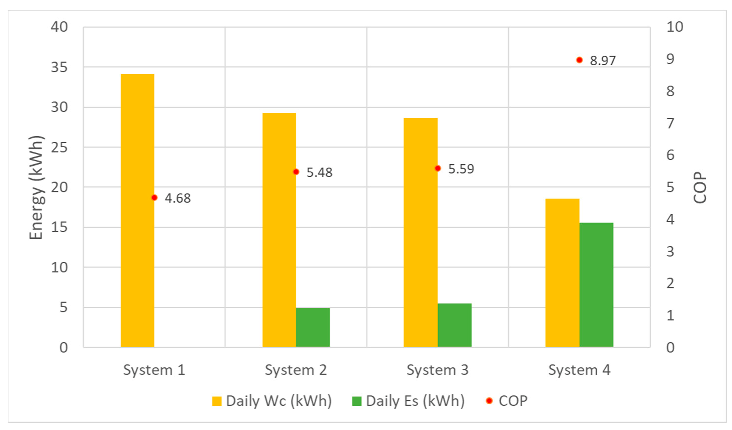
System 1. Reference air-sourced RAC system4.6834.16--
System 2. Fixed-speed CTDT-RAC system5.4829.244.9314.43%
System 3. Fixed-speed RTDT-RAC system5.5928.665.516.11%
System 4. Variable-speed RTDT-RAC system8.9718.5715.5845.59%
Disclaimer/Publisher’s Note: The statements, opinions and data contained in all publications are solely those of the individual author(s) and contributor(s) and not of MDPI and/or the editor(s). MDPI and/or the editor(s) disclaim responsibility for any injury to people or property resulting from any ideas, methods, instructions or products referred to in the content.

