
Research on Piston Dynamics and Engine Performances of a Free-Piston Engine Linear Generator Coupling with Various Rebound Devices

Abstract
:1. Introduction
1.1. Single-Cylinder/Single-Piston FPELG Structure Type Coupled with a Mechanical Spring
1.2. Single-Cylinder-Single/Piston Structure Type of the FPELG Coupling with the Gas Spring
1.3. Summary
2. Numerical Models of the FPELG Coupling with Various Rebound Devices
2.1. Numerical Models
2.2. Main Parameters Specification
3. Piston Dynamics and Engine Performances of the FPELG Coupling with Various Rebound Devices
3.1. Piston Dynamics
3.2. Engine Performances
4. FPELG Performances Sensitivity Discussion
4.1. Performances Sensitivity of the FPELG under Various Stiffness of the Mechanical Spring
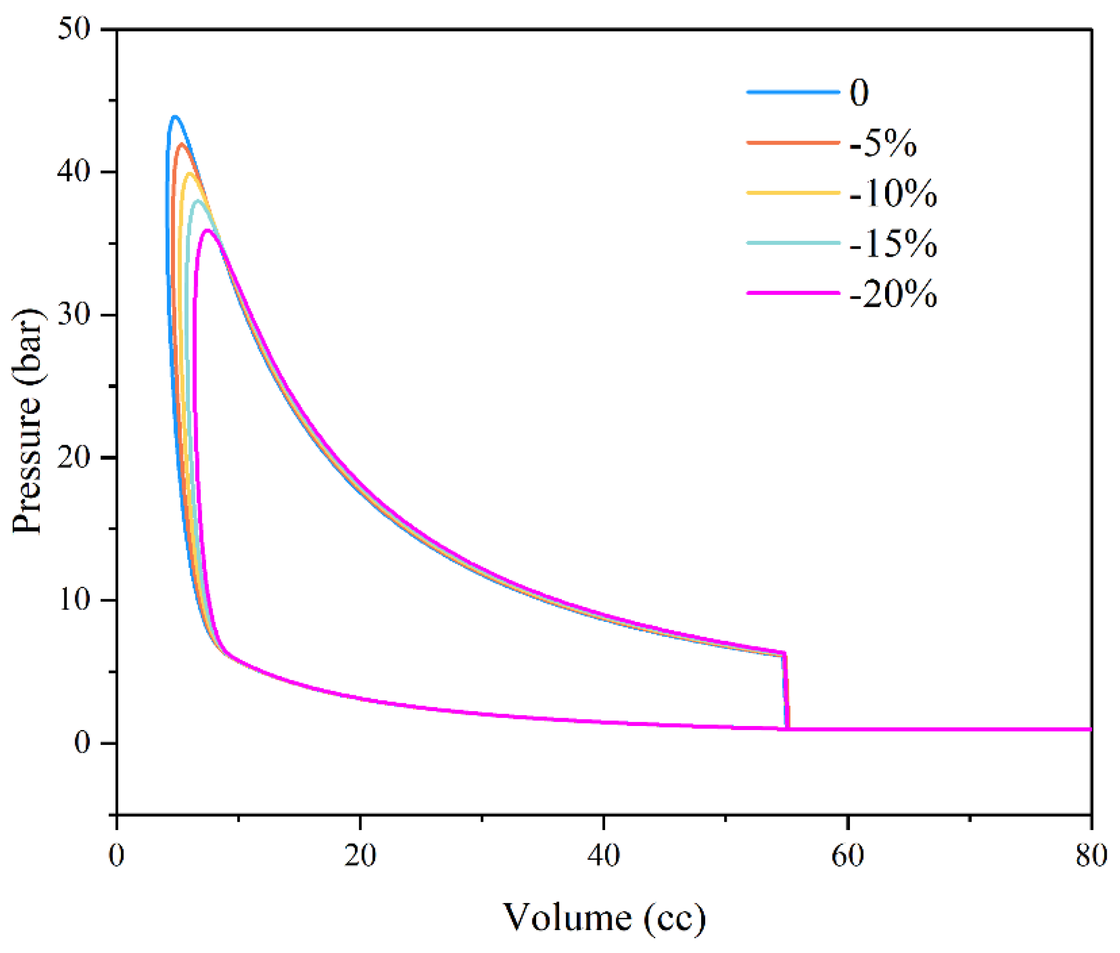
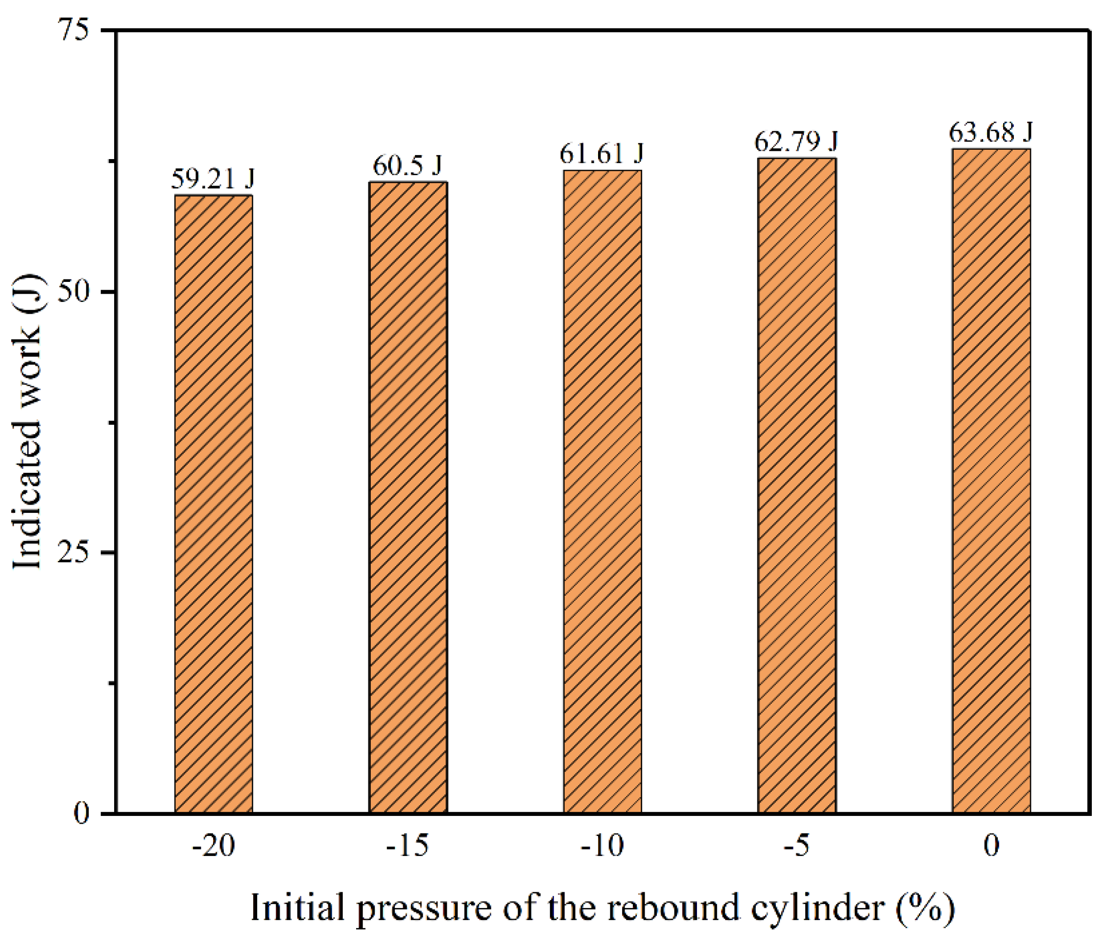
4.2. Performances Sensitivity of the FPELG under Various Initial Gas Pressure of the Gas Spring
5. Conclusions
- (1)
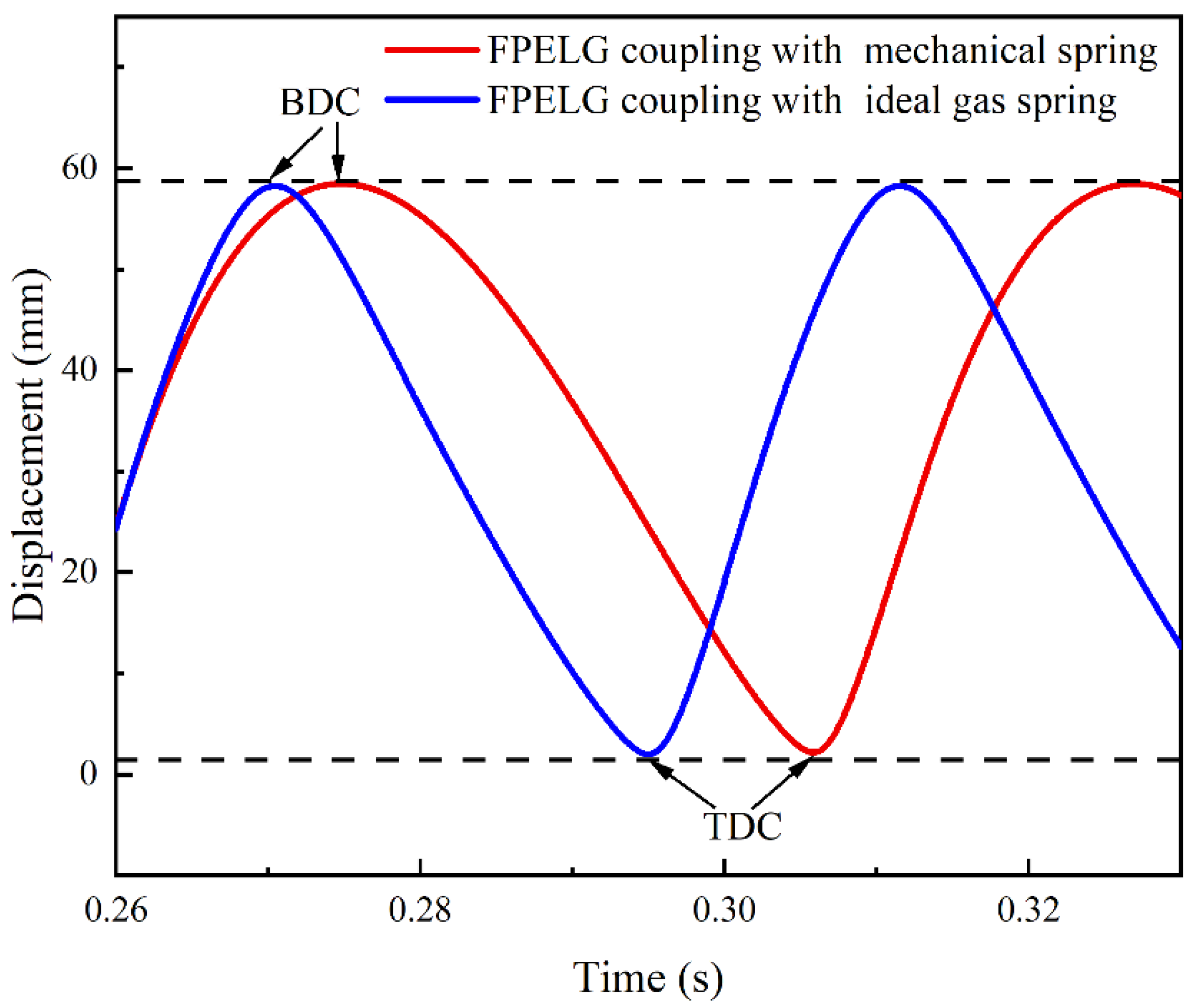
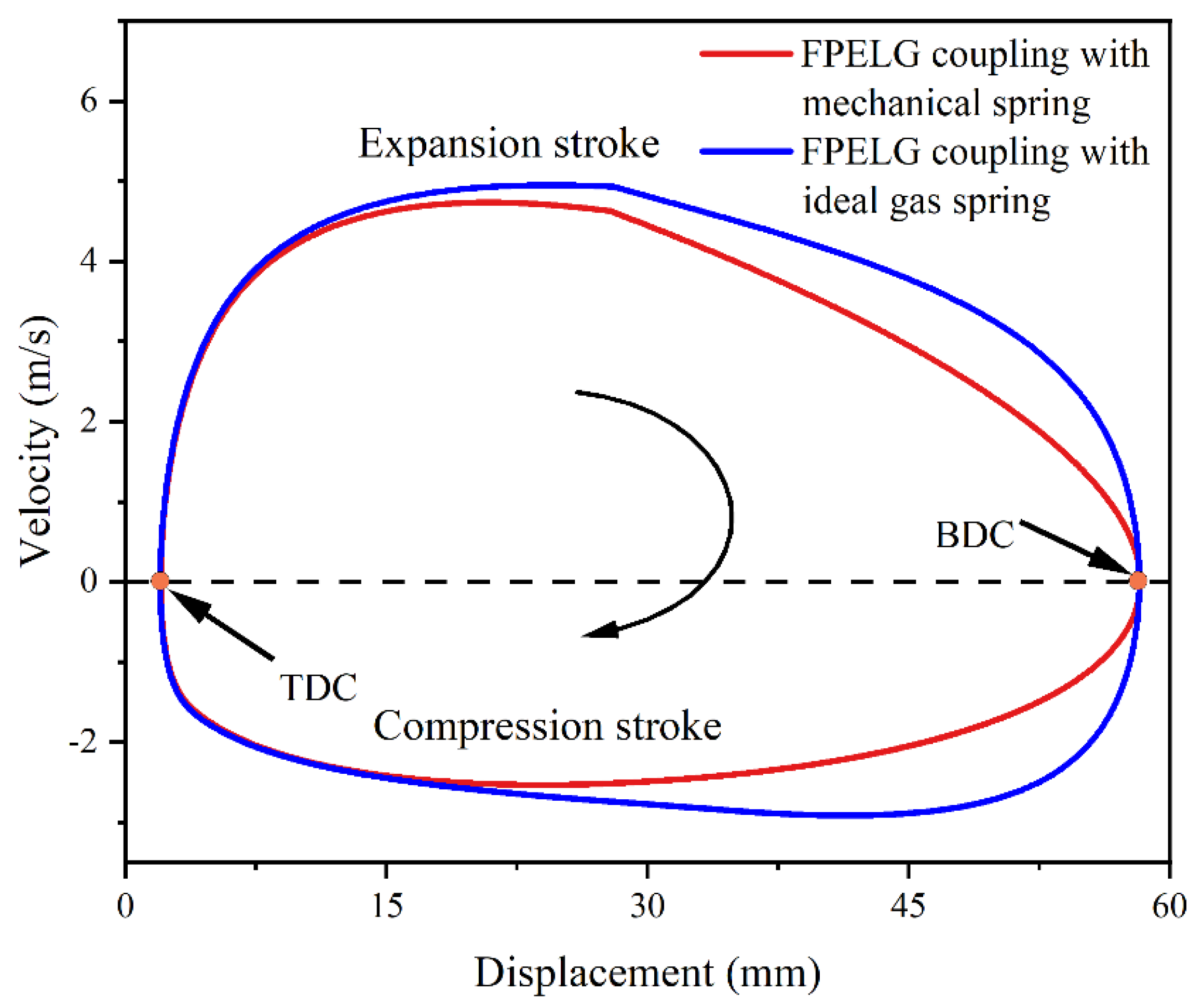
- When the equivalent stiffness of the gas spring is stronger than the stiffness of the mechanical spring, the piston operation frequency of the FPELG coupling with the gas spring is faster than that of the mechanical spring. The piston peak velocity of the FPELG during the expansion process is significantly faster than that during the compression process, regardless of whether the FPELG is coupled with the gas spring or the mechanical spring. Furthermore, the piston peak velocity of the FPELG coupling with the gas spring is faster than that of the mechanical spring. The piston velocity of the FPELG coupling with the mechanical spring changes linearly during the compression stroke, while the changing trend of the piston velocity of the FPELG coupling with the gas spring is nonlinear during the compression stroke.
- (2)
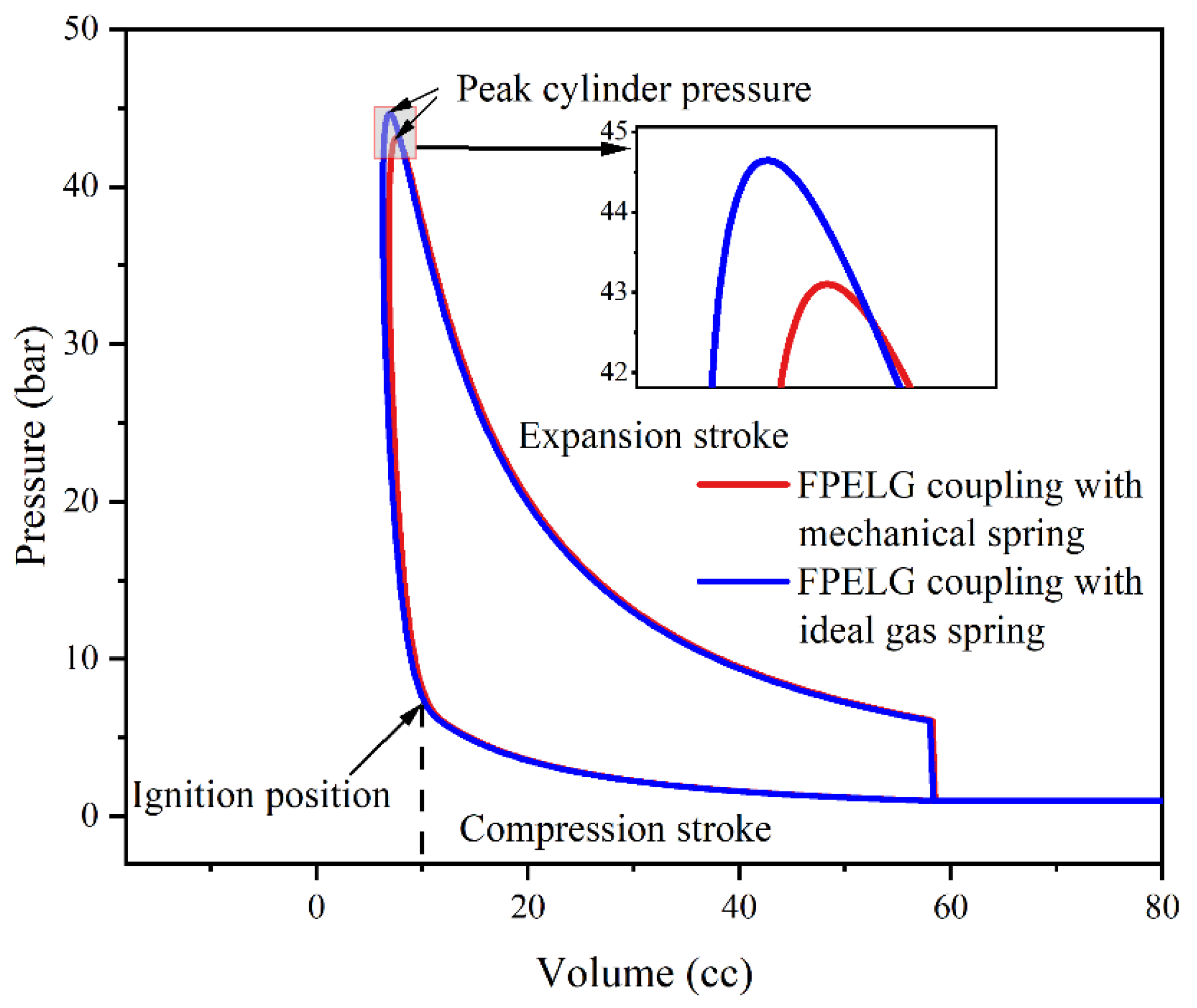
- The combustion process is similar to the constant-volume process, regardless of whether the FPELG coupling with the gas spring or the mechanical spring. The compression duration and expansion duration of the FPELG coupling with the gas spring are shorter than these of the mechanical springs. The thermal efficiency of the FPELG coupling with the ideal gas spring is 32.5%, compared to 32% for the mechanical spring. And the indicated power of the FPELG coupling with the ideal gas spring and the mechanical spring is 1.5 kW and 1.3 kW, respectively. However, compared to the ideal gas spring, the thermal efficiency of the FPELG coupling with the actual gas spring under leakage reduces by approximately 2.5%. And the indicated power and output power of the FPELG coupling with the gas spring under leakage both reduce by 10% and 12.5%, respectively.
- (3)
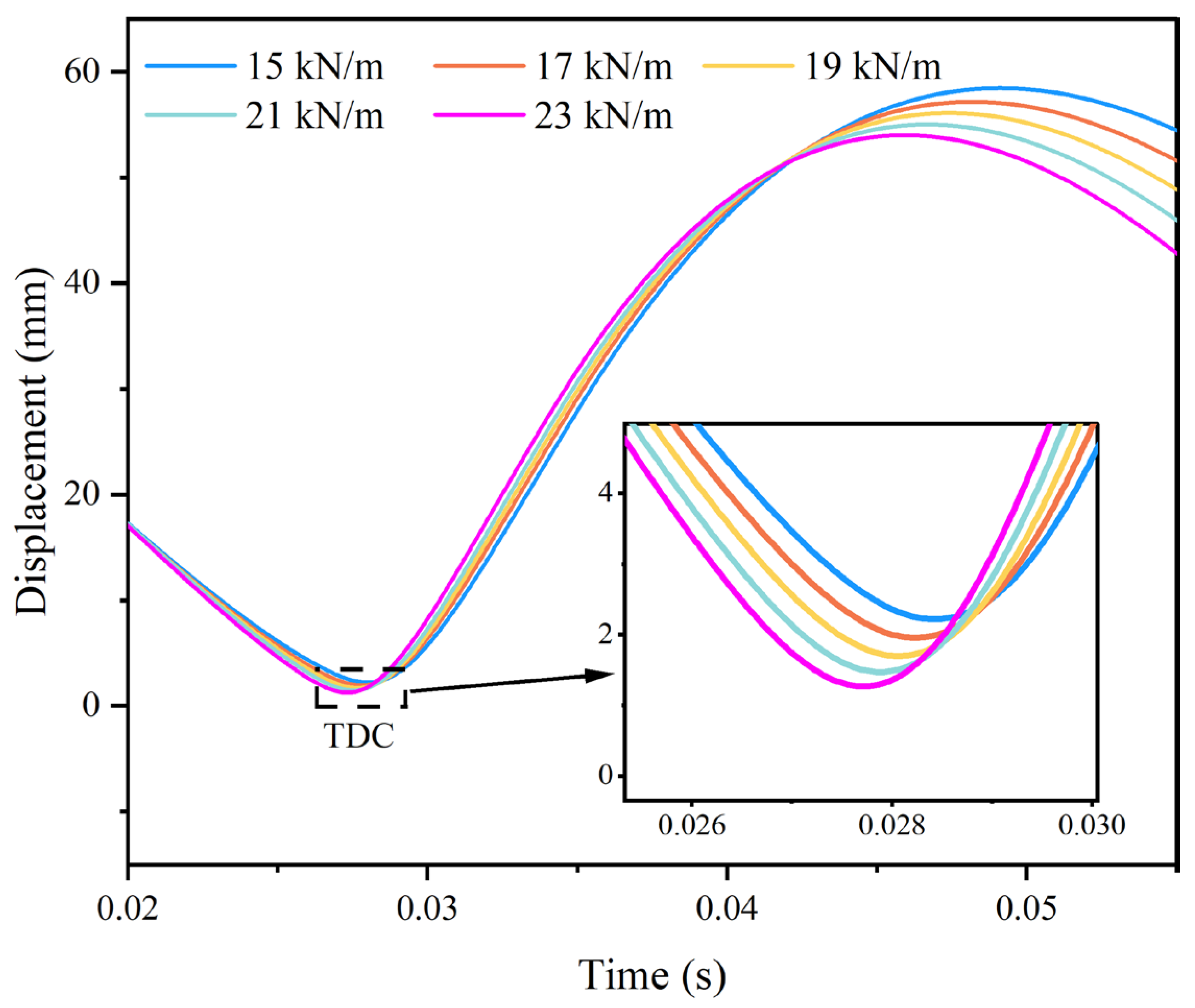
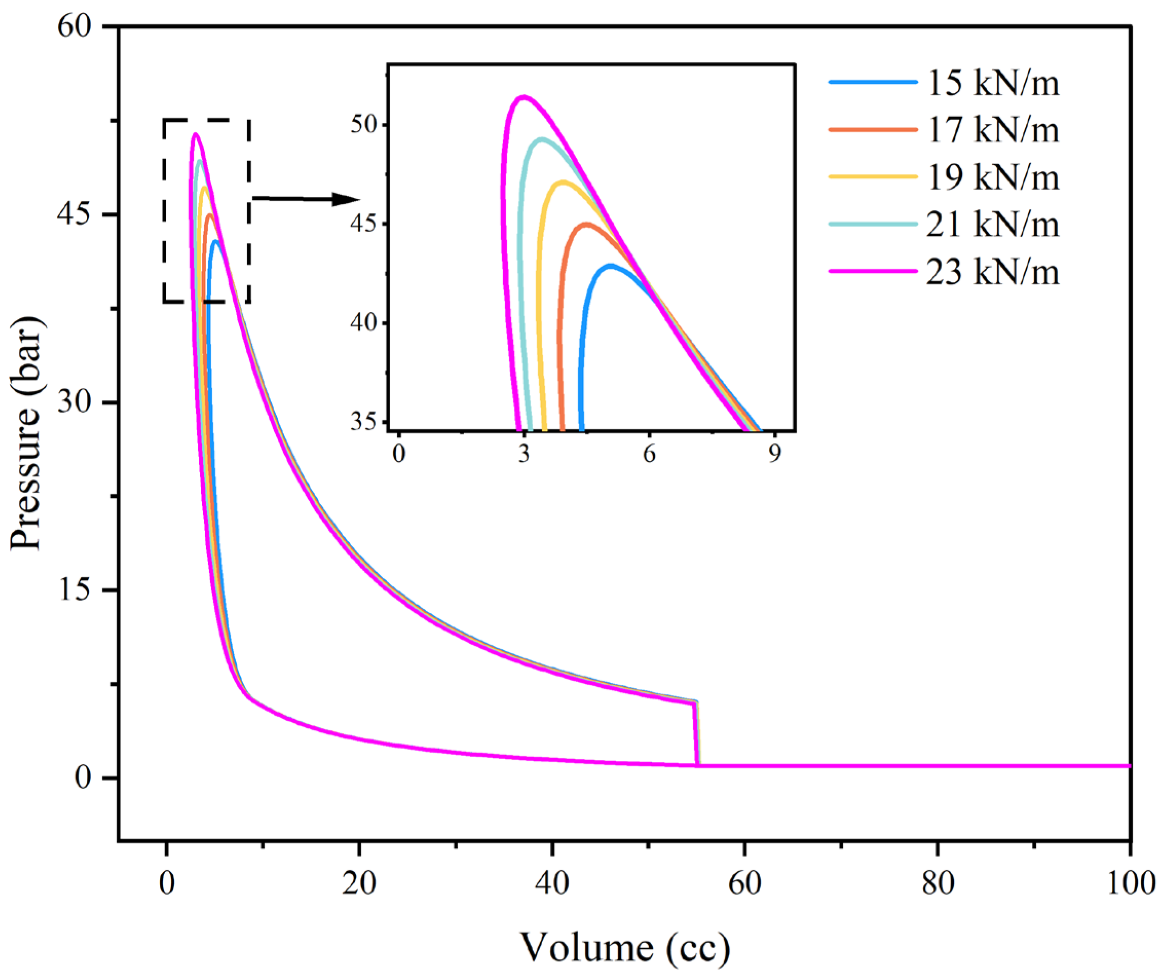
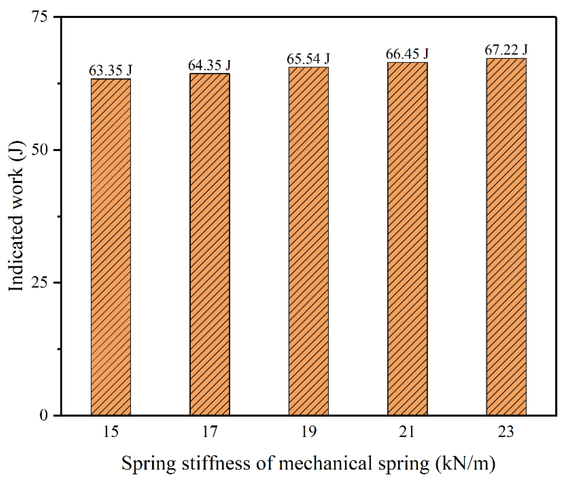
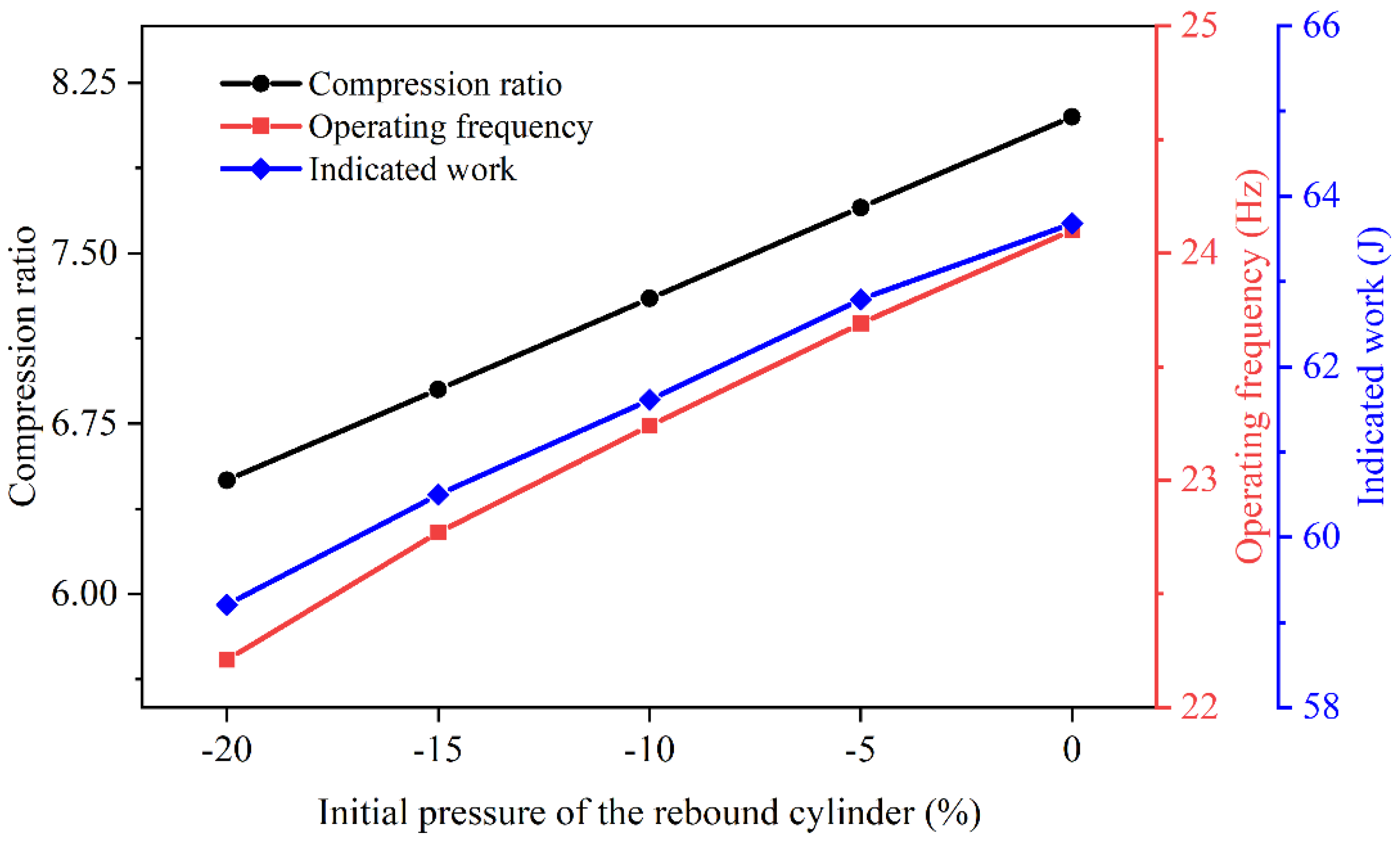
- As for the FPELG coupling with the mechanical spring, the TDC position is positively related to the stiffness of the mechanical spring, while the piston operation stroke length is inversely proportional to the stiffness of the mechanical spring. The operation frequency of the piston increases with the increase in the stiffness of the mechanical spring. The combustion process of the free piston engine is nearly closed to the isovolumetric process as the stiffness of the mechanical spring increases. The indicated work of the engine and the indicated thermal efficiency of the FPELG are positively relative to the stiffness of the mechanical spring. Regarding the FPELG coupling with the gas spring, the dynamics of the piston and performances of the engine changing trends of the initial gas pressure of the gas spring from low to high are similar to the increasing trend of the stiffness of the mechanical spring.
Author Contributions
Funding
Data Availability Statement
Acknowledgments
Conflicts of Interest
Nomenclature
| FPELG | Free piston engine linear generator | TDC | Top dead center |
| HCCI | Homogeneous Charge Compression Ignition | BDC | Bottom dead center |
| a | parameters in the Wiebe function (–) | p | pressure in the engine cylinder (bar) |
| A | area of the piston (m2) | pg | gas pressure from the rebound-cylinder of the rebound device (bar) |
| Ac | the area of the in-cylinder surface in contact with the gas (m2) | Q | input energy from the fuel in each cycle (J) |
| Ag | area of the rebound piston of the rebound device (m2) | Qht | heat released during the combustion process (J) |
| b | parameters in the Wiebe function (–) | Qin | heat released from the combustion process (J) |
| Cd | combustion duration (s) | RL | resistance of the external load (Ω) |
| Cf | coefficient of friction (–) | Rs | coil resistance (Ω) |
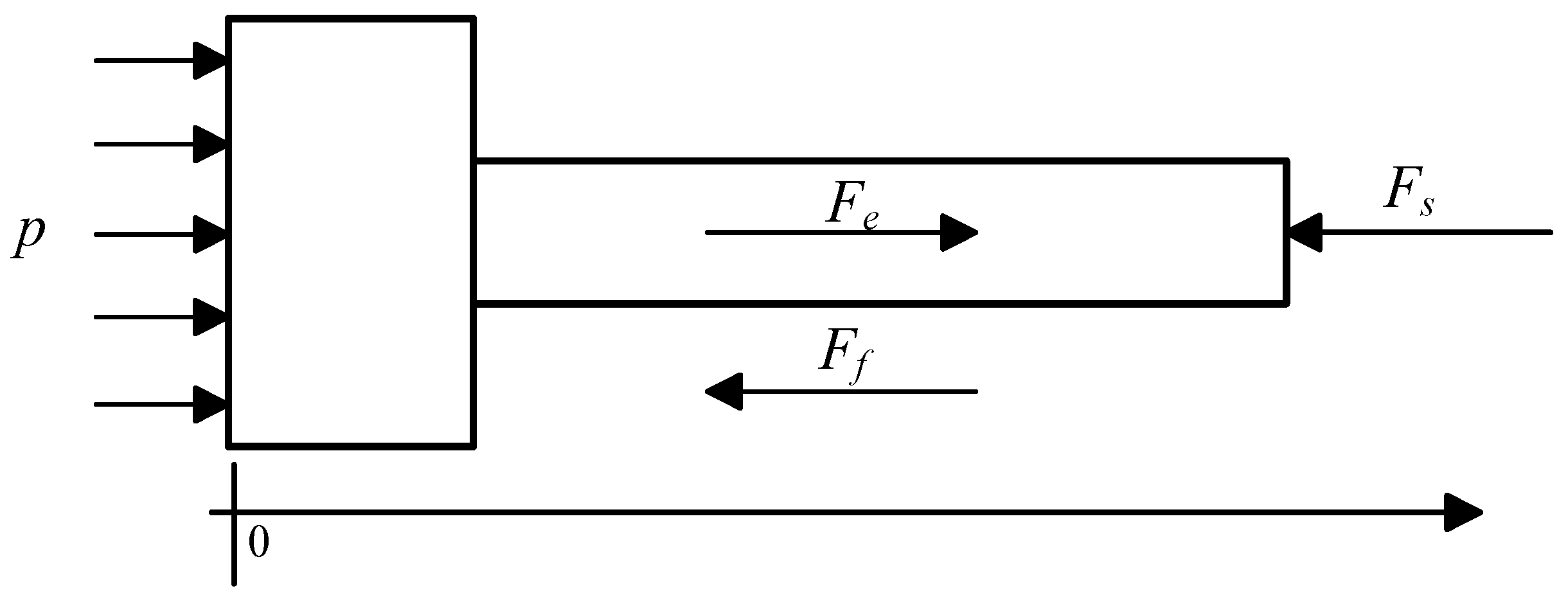
| Fe | electromagnetic resistance force of the linear generator (N) | t | Time (s) |
| Ff | friction force (N) | T0 | air temperature in the scavenging pump (K) |
| Fs | rebound force from the spring of the rebound device (N) | ts | starting combustion timing (s) |
| h | heat transfer coefficient (W/m2 K) | Tw | surface temperature of the cylinder wall (K) |
| kf | thrust force constant coefficient (N/A) | V | instantaneous cylinder volume of the free piston engine (m3) |
| kx | stiffness of the mechanical spring (KN/m) | Vg | instantaneous rebound-cylinder volume of the gas spring (m3) |
| kε | constant coefficient of the back EMF of the linear generator (V/m/s) | vp | mean piston velocity (m/s) |
| L | inductance of the linear generator (H) | x | the displacement of the piston and the rods of the linear generator and rebound device (mm) |
| m | mass of the piston and the rods of the linear generator and rebound device (kg) | γ | ratio of specific heats (–) |
References
- Irie, S.; Sato, M.; Mizuno, T.; Nishimura, F.; Naganuma, K. Effect of Nonlinear Spring Characteristics on the Efficiency of Free-Piston Engine Generator. Energies 2022, 15, 7579. [Google Scholar] [CrossRef]
- Miao, Y.; Zuo, Z.; Feng, H.; Guo, C.; Song, Y.; Jia, B.; Guo, Y. Research on the Combustion Characteristics of a Free-Piston Gasoline Engine Linear Generator during the Stable Generating Process. Energies 2016, 9, 655. [Google Scholar] [CrossRef]
- Brosnan, P.; Tian, G.; Zhang, H.; Wu, Z.; Jin, Y. Non-Linear and Multi-Domain Modelling of a Permanent Magnet Linear Synchronous Machine for Free Piston Engine Generators. Energy Convers. Manag. X 2022, 14, 100195. [Google Scholar] [CrossRef]
- Guo, C.; Zuo, Z.; Feng, H.; Jia, B.; Roskilly, T. Review of Recent Advances of Free-Piston Internal Combustion Engine Linear Generator. Appl. Energy 2020, 269, 115084. [Google Scholar] [CrossRef]
- Hung, N.B.; Lim, O. A Review of Free-Piston Linear Engines. Appl. Energy 2016, 178, 78–97. [Google Scholar] [CrossRef]
- Guo, C.; Feng, H.; Jia, B.; Zuo, Z.; Guo, Y.; Roskilly, T. Research on the Operation Characteristics of a Free-Piston Linear Generator: Numerical Model and Experimental Results. Energy Convers. Manag. 2017, 131, 32–43. [Google Scholar] [CrossRef]
- Mikalsen, R.; Roskilly, A.P. A Review of Free-Piston Engine History and Applications. Appl. Therm. Eng. 2007, 27, 2339–2352. [Google Scholar] [CrossRef]
- Bade, M.; Clark, N.N.; Robinson, M.C.; Famouri, P. Parametric Investigation of Combustion and Heat Transfer Characteristics of Oscillating Linear Engine Alternator. J. Combust. 2018, 2018, 2907572. [Google Scholar] [CrossRef]
- Bade, M.; Clark, N.; Famouri, P.; Guggilapu, P. Feasibility of Multiple Piston Motion Control Approaches in a Free Piston Engine Generator. SAE Int. J. Adv. Curr. Prac. Mobil. 2019, 2, 914–928. [Google Scholar] [CrossRef]
- Meymian, N.Z.; Clark, N.; Subramanian, J.; Heiskell, G.; Johnson, D.; Mahmudzadeh, F.; Darzi, M.; Musho, T.; Famouri, P. Quantification of Windage and Vibrational Losses in Flexure Springs of a One KW Two-Stroke Free Piston Linear Engine Alternator; SAE International: Warrendale, PA, USA, 2019. [Google Scholar]
- Robinson, M.C.; Clark, N. Fundamental Analysis of Spring-Varied, Free Piston, Otto Engine Device. SAE Int. J. Engines 2014, 7, 195–220. [Google Scholar] [CrossRef]
- Robinson, M.C.; Clark, N.N. Study on the Use of Springs in a Dual Free Piston Engine Alternator; SAE Technical Paper, No. 2016-01-2233; SAE International: Warrendale, PA, USA, 2016. [Google Scholar] [CrossRef]
- Bade, M.; Clark, N.N.; Famouri, P.; Guggilapu, P. Performance Comparison of a Single Cylinder and a Dual Cylinder Free Piston Engine. J. Eng. Gas Turbines Power 2019, 141, 081015. [Google Scholar] [CrossRef]
- Bade, M.; Clark, N.N.; Famouri, P.; Guggilapu, P. Translator Dynamics and Performance Comparison on One and Two Cylinder Free Piston Engines. In Proceedings of the ASME International Mechanical Engineering Congress and Exposition, Pittsburgh, PA, USA, 9 November 2018; American Society of Mechanical Engineers: New York, NY, USA; Volume 52071, p. V06AT08A039. [Google Scholar]
- Robinson, M.C.; Clark, N.N. Effect of Combustion Timing and Heat Loss on Spring-Assisted Linear Engine Translator Motion. SAE Int. J. Engines 2016, 9, 546–564. [Google Scholar] [CrossRef]
- Zhou, Y.; Sofianopoulos, A.; Gainey, B.; Lawler, B.; Mamalis, S. A System-Level Numerical Study of a Homogeneous Charge Compression Ignition Spring-Assisted Free Piston Linear Alternator with Various Piston Motion Profiles. Appl. Energy 2019, 239, 820–835. [Google Scholar] [CrossRef]
- Sofianopoulos, A.; Zhou, Y.; Lawler, B.; Mamalis, S. Gas Exchange Processes of a Small HCCI Free Piston Engine–A Computational Study. Appl. Therm. Eng. 2017, 127, 1582–1597. [Google Scholar] [CrossRef]
- Zhou, Y.; Gainey, B.; Hariharan, D.; Lawler, B.; Mamalis, S. Understanding HCCI Combustion in a Free Piston Engine with a Multi-Zone, Control-Mass Model with Thermal Stratification and Chemical Kinetics; SAE International: Warrendale, PA, USA, 2019. [Google Scholar]
- Lin, J.; Xu, Z.; Chang, S.; Yan, H. Finite-Time Thermodynamic Modeling and Analysis of an Irreversible Miller Cycle Working on a Four-Stroke Engine. Int. Commun. Heat Mass Transf. 2014, 54, 54–59. [Google Scholar] [CrossRef]
- Lin, J.; Xu, Z.; Chang, S.; Yin, N.; Yan, H. Thermodynamic Simulation and Prototype Testing of a Four-Stroke Free-Piston Engine. J. Eng. Gas Turbines Power 2014, 136, 051505. [Google Scholar] [CrossRef]
- Yan, H.; Xu, Z.; Lu, J.; Liu, D.; Jiang, X. A Reciprocating Motion Control Strategy of Single-Cylinder Free-Piston Engine Generator. Electronics 2020, 9, 245. [Google Scholar] [CrossRef]
- Tian, C.L.; Feng, H.H.; Zuo, Z.X. Oscillation Characteristic of Single Free Piston Engine Generator. Adv. Mater. Res. 2012, 383–390, 1873–1878. [Google Scholar] [CrossRef]
- Tian, C. Research on Motion Characteristics and Control Strategy of Linear Motor Type Free Piston Engine. Ph.D. Thesis, Beijing Institute of Technology, Beijing, China, 2012. [Google Scholar]
- Yuan, C.; He, L.; Zhou, L. Numerical Simulation of the Effect of Spring Dynamics on the Combustion of Free Piston Linear Engine. Energy 2022, 254, 124241. [Google Scholar] [CrossRef]
- Ferrari, C.; Friedrich, H.E. Development of a Free-Piston Linear Generator for Use in an Extended-Range Electric Vehicle. In Proceedings of the EVS26, Los Angeles, CA, USA, 6–9 May 2012. [Google Scholar]
- Haag, J.; Ferrari, C.; Starcke, J.H.; Stöhr, M.; Riedel, U. Numerical and Experimental Investigation of In-Cylinder Flow in a Loop-Scavenged Two-Stroke Free Piston Engine; SAE Technical Paper No. 2012–32–0114; SAE International: Warrendale, PA, USA, 2012. [Google Scholar]
- Haag, J.; Kock, F.; Chiodi, M.; Mack, O.; Bargende, M.; Naumann, C.; Slavinskaya, N.; Heron, A.; Riedel, U.; Ferrari, C. Development Approach for the Investigation of Homogeneous Charge Compression Ignition in a Free-Piston Engine; SAE Technical Paper No. 2013–24–0047; SAE International: Warrendale, PA, USA, 2013. [Google Scholar]
- Kock, F.; Haag, J.; Friedrich, H.E. The Free Piston Linear Generator—Development of an Innovative, Compact, Highly Efficient Range-Extender Module; SAE Technical Paper No. 2013–01–1727; SAE International: Warrendale, PA, USA, 2013. [Google Scholar]
- Schneider, S.; Rinderknecht, F.; Friedrich, H.E. Design of Future Concepts and Variants of The Free Piston Linear Generator. In Proceedings of the 2014 Ninth International Conference on Ecological Vehicles and Renewable Energies (EVER), Monte Carlo, Monaco, 25–27 March 2014; IEEE: Monte Carlo, Monaco, 2014; pp. 1–8. [Google Scholar]
- Schneider, S.; Friedrich, H.E. Experimental Investigation and Analysis of Homogeneous Charge Compression Ignition in a Two-Stroke Free-Piston Engine. SAE Int. J. Engines 2016, 9, 365–373. [Google Scholar] [CrossRef]
- Kosaka, H.; Akita, T.; Moriya, K.; Goto, S.; Hotta, Y.; Umeno, T.; Nakakita, K. Development of Free Piston Engine Linear Generator System Part 1—Investigation of Fundamental Characteristics; SAE International: Warrendale, PA, USA, 2014. [Google Scholar]
- Goto, S.; Moriya, K.; Kosaka, H.; Akita, T.; Hotta, Y.; Umeno, T.; Nakakita, K. Development of Free Piston Engine Linear Generator System Part 2—Investigation of Control System for Generator; SAE International: Warrendale, PA, USA, 2014. [Google Scholar]
- Moriya, K.; Goto, S.; Akita, T.; Kosaka, H.; Hotta, Y.; Nakakita, K. Development of Free Piston Engine Linear Generator System Part 3—Novel Control Method of Linear Generator for to Improve Efficiency and Stability; SAE International: Warrendale, PA, USA, 2016. [Google Scholar]
- Sun, P.; Zhang, C.; Chen, J.; Zhao, F.; Liao, Y.; Yang, G.; Chen, C. Decoupling Design and Verification of a Free-Piston Linear Generator. Energies 2016, 9, 1067. [Google Scholar] [CrossRef]
- Sun, P.; Zhang, C.; Chen, J.; Zhao, F.; Liao, Y.; Yang, G.; Chen, C. Hybrid System Modeling and Full Cycle Operation Analysis of a Two-Stroke Free-Piston Linear Generator. Energies 2017, 10, 213. [Google Scholar] [CrossRef]
- Zhang, C.; Chen, F.; Li, L.; Xu, Z.; Liu, L.; Yang, G.; Lian, H.; Tian, Y. A Free-Piston Linear Generator Control Strategy for Improving Output Power. Energies 2018, 11, 135. [Google Scholar] [CrossRef]
- Jia, B.; Tian, G.; Feng, H.; Zuo, Z.; Roskilly, A.P. An Experimental Investigation into the Starting Process of Free-Piston Engine Generator. Appl. Energy 2015, 157, 798–804. [Google Scholar] [CrossRef]
- Mao, J. Numerical Simulation and Experimental Analysis of Free-Piston Linear Alternator; Beijing Institute of Technology: Beijing, China, 2011. [Google Scholar]
- Yuan, C.; Jing, Y.; Liu, C.; He, Y. Effect of Variable Stroke on Fuel Combustion and Heat Release of a Free Piston Linear Hydrogen Engine. Int. J. Hydrogen Energy 2019, 44, 20416–20425. [Google Scholar] [CrossRef]
- Mao, J.; Zuo, Z.; Li, W.; Feng, H. Multi-Dimensional Scavenging Analysis of a Free-Piston Linear Alternator Based on Numerical Simulation. Appl. Energy 2011, 88, 1140–1152. [Google Scholar] [CrossRef]
- Brosnan, P.; Tian, G.; Montanaro, U.; Cockerill, S. A Comprehensive Review of the Free Piston Engine Generator and Its Control. IJAMM 2023, 2, 27. [Google Scholar] [CrossRef]
- Wu, L.; Feng, H.; Zhang, Z.; Jia, B.; Wang, J.; Yang, F.; Lei, Q. Experimental Analysis on the Operation Process of Opposed-Piston Free Piston Engine Generator. Fuel 2022, 325, 124722. [Google Scholar] [CrossRef]


| Numerical Model | FPELG Coupling with the Mechanical Spring | FPELG Coupling with the Gas Spring | |
|---|---|---|---|
| FPELG dynamic model | |||
| Thermodynamic sub-model of free piston engine | Compression | ||
| Combustion | |||
| Expansion | |||
| Exhaust | |||
| Linear generator model | |||
| Friction sub-model | |||
| Rebound device model | |||
| Parameters (Unit) | FPELG Coupling with the Mechanical Spring | FPELG Coupling with the Gas Spring |
|---|---|---|
| Mover mass (kg) | 4 | 4 |
| Stroke (mm) | 60 | 60 |
| Engine cylinder bore (mm) | 50 | 50 |
| Rebound cylinder bore (mm) | — | 80 |
| Stiffness of the spring (kN/m) | 15 | — |
| Constant of back electromagnetic voltage (V/ms−1) | 70 | 70 |
| Thrust force constant (N/A) | 82 | 82 |
| FPELG Coupling with Mechanical Spring | FPELG Coupling with Ideal Gas Spring | FPELG Coupling with Actual Gas Spring | |
|---|---|---|---|
| Equivalent rotational speed (rpm) | 1151 | 1443 | 1368 |
| Peak piston velocity (m/s) | 4.69 | 4.9 | 4.7 |
| Compression ratio (–) | 8.1 | 8.1 | 7.2 |
| Fuel consumption (kg/kW h) | 0.20 | 0.20 | 0.20 |
| Peak pressure (bar) | 42.3 | 44.4 | 37 |
| Indicated thermal efficiency (%) | 32 | 32.5 | 30 |
| Indicated power (kW) | 1.3 | 1.5 | 1.35 |
| Output electric power (W) | 1140 | 1412 | 1231 |
| Mechanical Spring Stiffness (kN/m) | Equivalent Rotational Speed (Rpm) | Peak Gas Pressure (Bar) | Peak Piston Velocity (m/s) | Compression Ratio (−) |
|---|---|---|---|---|
| 15 | 1140 | 42.3 | 4.69 | 8.1 |
| 17 | 1207 | 44.7 | 4.73 | 8.6 |
| 19 | 1260 | 46.8 | 4.77 | 9.3 |
| 21 | 1309 | 49.02 | 4.81 | 9.9 |
| 23 | 1357 | 51.1 | 4.85 | 10.7 |
Disclaimer/Publisher’s Note: The statements, opinions and data contained in all publications are solely those of the individual author(s) and contributor(s) and not of MDPI and/or the editor(s). MDPI and/or the editor(s) disclaim responsibility for any injury to people or property resulting from any ideas, methods, instructions or products referred to in the content. |
© 2023 by the authors. Licensee MDPI, Basel, Switzerland. This article is an open access article distributed under the terms and conditions of the Creative Commons Attribution (CC BY) license (https://creativecommons.org/licenses/by/4.0/).
Share and Cite
Guo, C.; Wang, Y.; Tong, L.; Feng, H.; Zuo, Z.; Jia, B. Research on Piston Dynamics and Engine Performances of a Free-Piston Engine Linear Generator Coupling with Various Rebound Devices. Energies 2023, 16, 6570. https://doi.org/10.3390/en16186570
Guo C, Wang Y, Tong L, Feng H, Zuo Z, Jia B. Research on Piston Dynamics and Engine Performances of a Free-Piston Engine Linear Generator Coupling with Various Rebound Devices. Energies. 2023; 16(18):6570. https://doi.org/10.3390/en16186570
Chicago/Turabian StyleGuo, Chendong, Yahui Wang, Liang Tong, Huihua Feng, Zhengxing Zuo, and Boru Jia. 2023. "Research on Piston Dynamics and Engine Performances of a Free-Piston Engine Linear Generator Coupling with Various Rebound Devices" Energies 16, no. 18: 6570. https://doi.org/10.3390/en16186570