Article

Revitalization Modelling of a Mature Oil Field with Bottom-Type Aquifer into Geothermal Resource—Reservoir Engineering and Techno-Economic Challenges

by
Martina Tuschl
1,* and
Tomislav Kurevija
2
1
Croatian Hydrocarbon Agency, 10000 Zagreb, Croatia
2
Faculty of Mining, Geology and Petroleum Engineering, University of Zagreb, 10000 Zagreb, Croatia
*
Author to whom correspondence should be addressed.
Energies 2023, 16(18), 6599; https://doi.org/10.3390/en16186599
Submission received: 9 August 2023 / Revised: 8 September 2023 / Accepted: 11 September 2023 / Published: 13 September 2023
(This article belongs to the Special Issue Development and Utilization in Geothermal Energy)

Abstract

:
The possibilities of using geothermal energy are slowly expanding to all areas of energy consumption, so the assessment of geothermal potential has become the backbone of energy policies in countries that have the potential. Countries and companies that have experience in the oil and gas industry are increasingly exploring the possibilities of first using the acquired knowledge, and then using the existing oil and gas infrastructure for the use of geothermal energy. For this reason, it is necessary to analyse the possibilities of using the existing infrastructure with all its limitations to maximise the energy potential of geothermal energy. The existing oil infrastructure, especially the wells, is in many cases not suitable for the production of brine and it is necessary to analyse the maximum impact of each well for the production of geothermal energy, with particular attention to the equipment installed in the well and the thickness of the geothermal reservoir in the oil and gas fields that would be suitable for the production of brine.

1. Introduction

Geothermal energy has its advantages over other renewable energy sources as it is available 24/7, but for almost 10 years the total capacity of installed geothermal energy has been growing slowly. According to IRENA [1], a total of 14,877 MW of geothermal energy was installed worldwide in 2022, with an average increase of 3.31% in installed capacity since 2013. In Europe, 1634 MW were installed in 2022, with an average growth of 1.23% compared to 2013, although there was no new installed capacity in 2022 compared to 2021. Although geothermal energy has a local character and depends on the geological conditions for its extraction, the growth share of geothermal energy is extremely slow.
Apart from the geological predetermination of a particular area, one of the reasons for the slow development of geothermal energy is its high price. The cost of drilling a geothermal well accounts for 40–50% of the total capital investment in a geothermal project [2]. Augustine et al., 2006 [3], note that the cost of drilling geothermal wells is even higher than the cost of drilling oil or gas wells at the same depth, as in the oil and gas industry, the costs of geothermal exploration drilling are financed by the investor’s equity. As the discovery risk at this stage is high and the use of equity is required to finance the drilling, geothermal energy is not attractive to investors. There is great learning potential in the construction of geothermal wells, especially with regard to the typical formations that are geothermal targets. However, when the specifics of geothermal well equipment are taken into account, they have a greater wellbore stability, but at the same time, this means a higher capital investment [4]. In order to increase the use of geothermal energy, especially with a view to reducing costs, countries that have already produced oil and gas in the past are examining their geothermal energy potential on the basis of abandoned oil and gas wells [5]. Oil fields have the potential for low to medium geothermal energy resources and have a wealth of data that should be used to reuse the fields and improve the technology for extracting geothermal energy from them [6]. The knowledge gained from the characterisation of the reservoirs, but also the political regulations in the petroleum industry, can help to expand the use of geothermal energy [7]. Appropriate solutions are already being applied, both in terms of regulatory possibilities and technical issues in the conversion of oil and gas fields to geothermal energy production, and in the use of the data provided by oil and gas activities for geothermal reservoir engineering [8,9,10].
In Croatia, the oil industry has a long tradition dating back to 1950, when the first oil and gas explorations took place. Along with the oil and gas discoveries, geothermal potential was also discovered, but not exploited in the energy sector. After more than 60 years of continuous production in Croatia, the depletion of oil and gas reservoirs is reaching its peak and many fields are about to be shut down. In the future, it will be necessary to invest significant funds for decommissioning, while, on the other hand, there is the potential for renewable energy in the form of deep and hot aquifers in old oil and gas reservoirs. To implement the Green Deal guidelines for the successful transition from fossil fuels to renewable energy, the use of aquifers from depleted oil and gas fields is of best practise in this direction, especially in terms of using the findings from deep oil and gas fields for use as renewable energy sources.

2. Materials and Methods

Geothermal energy can be used in various ways, from direct application in district heating, greenhouse heating, industrial processing, etc., to the generation of electricity, depending on the temperature and flow of the geothermal brine [11,12,13,14].
The conversion of oil fields into geothermal energy is the interest of many authors, as is the methodology for finding the best scenarios for extracting geothermal energy from aquifers and the methodology for selecting the best fields for this purpose [15,16,17,18,19,20,21,22]. Retrofitting oil wells is an idea that is gaining popularity as a possibility for using wells with deep heat exchangers [22,23]. Davis and Michaelides [24] analysed the potential of oil wells equipped with double-pipe heat exchangers and the use of secondary fluid as the working fluid. In this way, the net power produced can exceed 3 MW for temperatures at the bottom of the well of 450 K. Gharibi et al. [25] evaluates the feasibility of obtaining geothermal energy from an abandoned oil well that has been retrofitted with a U-tube heat exchanger and concludes that the obtained thermal energy can be used for direct application, and even for the production of electricity in certain circumstances. An example of using oil wells to generate geothermal energy was also presented by Wang et al. [26], through downhole power generation using thermoelectric generation technology.
In addition to the data available from oil and gas production, the use of existing wells lowers the cost of the future exploitation of geothermal wells. The use of abandoned oil and gas wells for geothermal energy also presents its own challenges, primarily relating to the selection of suitable wells, the availability of data and, above all, the integrity of the wells [27]. Among other challenges, according to Liu, 2018 [28], oil fields as geothermal resources are in the range of 65 to 150 °C, which belongs to the medium to low temperature category according to the classifications of many authors [29], and the method of exploitation should be adapted to the given conditions.
To classify geothermal energy, it is not enough to determine only the temperature, but it is necessary to determine its working capacity, i.e., the possibility of producing electricity or thermal energy [30]. According to Rybach, 2015 [31], renewable energy resources can be divided into five categories: theoretical, technical, economic, sustainable and development potential, which decrease in size and thus also maintain their financial framework.
The theoretical potential of geothermal water can be determined using Heat in Place, which describes the energy contained in the solid phase and the energy contained in the pores or water [32,33,34]. In order to calculate the heat contained in rock and the heat contained in water separately, the following expression is used:
H i = H r   + H w   = Φ   ρ w   c w   V i   T i T 0 + 1 Φ ( ρ r   c r )   V i T i T 0  
where Hi is the total volumetric heat of the rock and water (J), while Hr and Hw are the total volumetric heat contained in the rock and water, respectively (J); ϕ is the reservoir porosity, while c is the heat capacity (kJ/m3/°C), the index r refers to the rock and the index w refers to the water. Vi is the volume of the rock and water (m3), Ti is the initial temperature of the reservoir (°C) and T0 is the initial temperature of the water (°C).

2.1. Organic Rankine Cycle

In terms of oil field temperature, the geothermal potential ranges from the low to the medium category [28]; energy from an oil field geothermal aquifer can be generated using an Organic Rankine Cycle (ORC). ORC power plants work on the principle of the Rankine cycle but use organic substances as the working medium (typical working fluids are isobutane, isopentane, R-134a and ammonia) instead of water. In the ORC, the heat coming from the geothermal aquifer heats the working fluid, whose steam then drives the turbine, whose rotary motion is transferred to the generator, which converts the kinetic energy into electricity. The working fluid is cooled in the condensers and returned to the circuit in the form of a liquid phase, and the process continues. When using ORC technology, special attention must be paid to the selection of the working fluid, the temperature and pressure of the condenser, the cooling medium and the choice of expander technology [35] in order to obtain optimal plant efficiency [36,37]. ORC power plants are particularly useful in situations where the heat sources are not strong enough to operate a classical steam power plant using water as the working medium, as they use low- and medium-temperature sources (<90–150 °C) [38] and are suitable for use with low and medium geothermal energy potential. The maximum theoretical output of the ORC, without taking into account heat transfer losses and the internal consumption of the power plant, is calculated using the potential maximum useful work corresponding to the change in the availability of the brine and the dead state under ambient or sink conditions [39]:
P ex = q g × Δ h T 0 × Δ s   T g   , p g ;   T 0 ,   p 0
Change in enthalpy:
Δ h = h h 0 = c pg × T T 0
Change in entropy:
Δ s = s s 0 = c pg × ln T T 0
For constant pressure:
s = T 0 T c Pg T dT R ln p p 0 + s 0
P ex = q g × c pg Δ T T 0 × ln 1 + Δ T T 0 ¯
P ex = q g × c pg Δ T T 0 Δ T T 0 1 2 Δ T 2 T 0 2
Final equation for the power output:
P ex = q g × C pg Δ T 2 2 T g   out
where Pex is maximum theoretical power, qg is the mass fluid flow, cpg is the specific heat of the geothermal fluid, T0 presents site conditions and Tg out is the outlet temperature from the binary power plant heat exchanger.
The same relation could be defined through the First and Second Laws of thermodynamics:
P ex = q g × c pg Δ T T 0 × ln T g   in T g   out ¯ × η util
The Second Law efficiency (ηutil) for a given process is the ratio between the real work and the reversible work for a fictitious reversible process. For the Rankine cycle, the efficiency can be expressed as a function of the operating conditions of the cycle as well as the conditions of the sink and the brine temperatures:
η util = Δ T   × η cycle Δ T T 0 × ln T g   in T o
The thermodynamic efficiency of the binary power plant (ηcycle), or the efficiency described by the First Law of Thermodynamics, is the ratio between the net power developed by the cycle (Pex) and the total available thermal energy from the geothermal source (Qtot) at the surface [38]:
η cycle = P ex Q tot   = q g   ×   c pg   ×   Δ T 2 2   ×   Tgout q g × c pg × Δ T = Δ T 2 × T g   out

2.2. Well Completion

The function of the well is to provide a connection between the surface and the reservoir in order to pump or inject fluid. The effectiveness of this connection affects the production characteristics of the reservoir, the total production achieved and the economics. Well completion is considered the most important operation during the life of the well. It includes almost all operations between the development of the well and the commissioning of the well [40]. The method of completion depends on and influences the production and future maintenance operations simultaneously. In general, the technology used in drilling petroleum wells and geothermal wells is very similar, with the choice of casing used in the drilling and the subsequent completion of the geothermal wells depending on the temperature, depth, the properties of the geothermal brine and the production characteristics that the well must achieve [41]. When drilling wells, casing is placed in the wellbore, considering the design and purpose of the well. The production interval can be completed in two basic ways—as an open hole and a cased hole [42]. Open holes are most commonly drilled in carbonate (consolidated) reservoirs. In this completion method, the casing is laid to the top of the production interval and cemented before the production zone is drilled through. Then, the open part of the well is drilled. A cased well means that the entire reservoir interval is cased and then perforated. The typical completion of oil wells in Croatia involves cased wells with a perforated production interval, where the outer diameter of the production casing is between 5 and 5 ½″. The typical completion of oil wells in Croatia poses the greatest challenge to the use of the wells for geothermal energy. Geothermal wells are typically completed in such a way that the size of the wells in the production casing is between 13 3/8″, 9 5/8″ and 7″, while the diameters in the open hole are between 9 5/8″, 7″ and 5 ½″ [4,41]. Due to the high temperatures, the casing is exposed to greater stress and must be cemented along its entire length [43].

2.3. Economic Evaluation

Financial decisions on long-term investments are some of the most complex decisions. An investment in long-term, real projects means an investment in fixed, tangible assets of a company. Therefore, investments in long-term projects are considered as investments in fixed assets that require the use of current assets. Geothermal projects represent a large capital burden, and reducing costs in the form of investment in the construction of new wells is an important contribution to reducing the initial investment [44,45]. The most common method for estimating the time value of capital is the net present value. Net present value is calculated by summing the future cash inflows, reduced to today’s costs, over the life of the project.
NPV = t = 1 t CF 1 + WACC t
where CF is the net cash inflows and outflows during the project period (t) and WACC is the weighted average cost of capital.
The weighted average cost of capital (WACC) represents the ratio between the assets the company is willing to invest, and the share of debt and business risk [46]. The WACC is used to estimate the cost of capital and thus the return that an investor receives for his investment. The capital asset pricing model (CAPM model) [47] estimates the weighted average cost of the capital. It introduces a risk-free interest rate as a variable representing the minimum return an investment can receive and combines it with the industry beta coefficient and the market return. The model CAMP was introduced by Sharp in 1964 [48] and is the basic method for estimating the cost of capital despite its shortcomings [49,50].
WACC = (   W E × r e   ) + W D × r d × 1 t c
where WE is the weighted value of equity, re is the cost of equity, WD is the weighted value of debt, rd is the cost of debt and tc is corporate tax.
r e =   r f + β L × r m r f
where re is cost of equity, rf is the risk-free rate, rm is the expected return and β L is the levered beta for equity.

2.4. Selection of Mature Oil Fields for Geothermal Production

In Croatia, oil and gas are produced from 54 fields. Of these, 42 are oil fields that are in the secondary phase of exploitation and where waterflooding is used to increase oil production [51]. This also means that the aquifers of these oil fields are approximately at the initial pressure level. If the temperature parameters are favourable for the extraction of geothermal water and there is the possibility of sufficient water inflow, these aquifers can be converted into geothermal fields and the existing infrastructure can be used for the production of renewable energy sources. This study analyses an oil field and the possibility of converting the oil field aquifer into a geothermal aquifer with existing oil production from shallower, oil-saturated reservoirs.
In order to examine the possibilities of repurposing oil fields, the Beničanci oil field was analysed. The field is located in the northern part of Slavonia in the Drava Depression, one of the four depressions in the Croatian part of the Pannonian Basin [52,53]. The analysed oil field was discovered in 1969 and production began in 1972 with 17 wells, and a total of 90 wells were drilled by the end of the 1970s. The well network is designed so that the wells are about 500 m apart. In the initial phase, oil production took place under the influence of the elastic energy regime, as there was no information about the influence of the aquifer. Currently, in the analysed oil field, 25 wells are producing oil, together with 10 injection wells, while the rest of the wells are shut-in or used as monitoring wells.
The structure of the oil reservoir is an elongated anticline (brachyanticline) extending from east to west, about 8 km long and 1.3 km wide. The following sequences of stratigraphic deposits were drilled—Mesozoic, Neogene and Quaternary (Figure 1). The oil reservoir mainly belongs to Badenian dolomite–limestone breccia of the Miocene age. The basic tectonic element of the field is a fault of reverse character, extending from the northwest to the southeast, and three zones of normal faulting have been identified in the western, central and eastern parts of the structure. It is considered that the oil reservoir, and consequently the geothermal reservoir, i.e., the aquifer of the oil field, constitutes a single hydrodynamic unit with a unique oil–water contact at −1955 m, and it is considered that the fault is not an obstacle to fluid flow (Figure 2) [54].
The average porosity is 10% but varies from 4.6% to 14.5% due to the fracture system in the deposit. The initial reservoir pressure was 191 bar, and the initial reservoir temperature was 123.3 °C at the depth of −1877 m. Based on the test data, the temperature also varies between 94 and 141.7 °C.
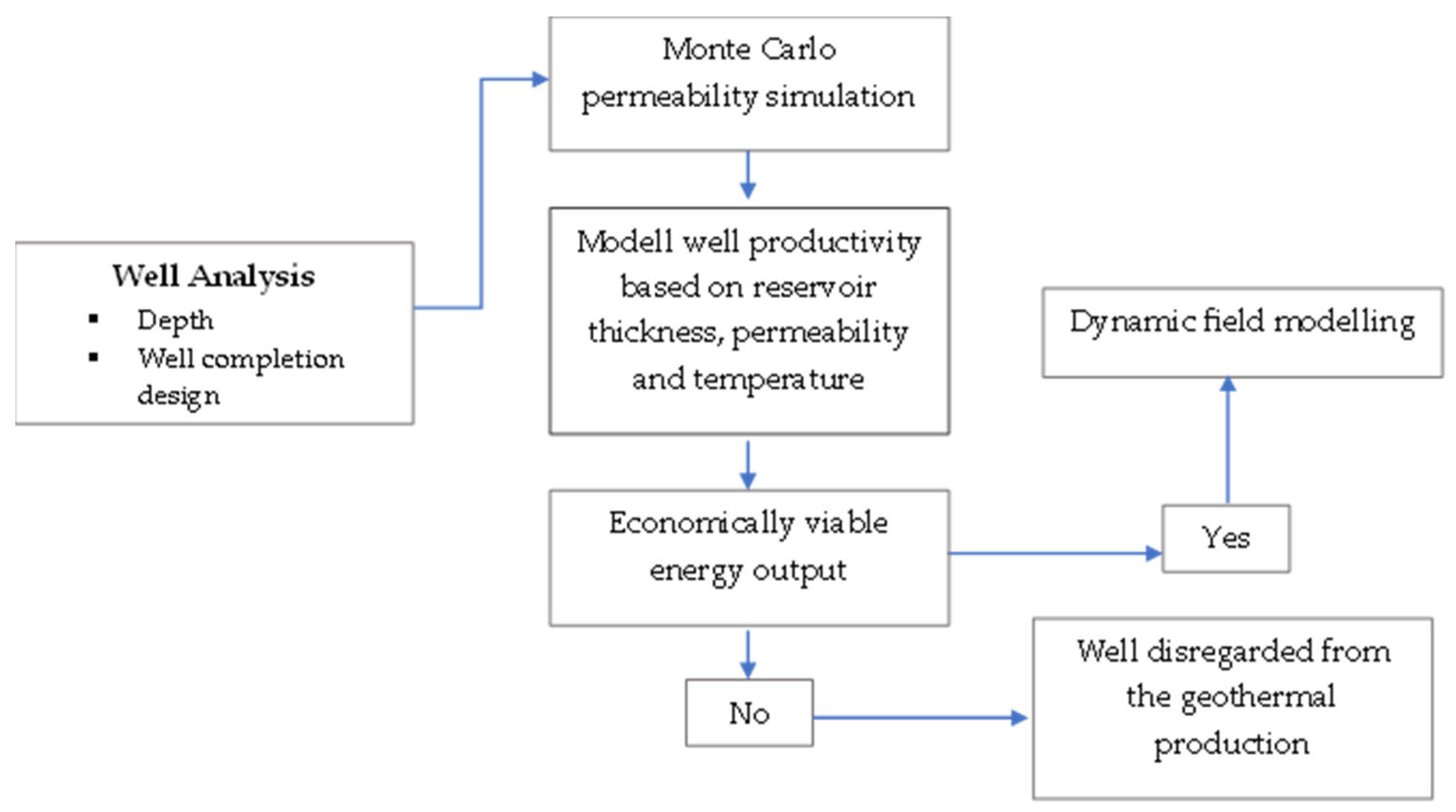
The aim of this work is to analyse the oil field, which is still in production, in such a way that a selection of wells can be made that could economically generate electricity from the geothermal aquifer of the oil field. To do this, it is first necessary to identify the wells that are not being used for oil production, the thickness of the geothermal aquifer tapped by these wells and the completion of each well. After a preliminary analysis of the fund of wells, the conditions under which each well represents an economic source of geothermal energy must be determined, i.e., the risk involved in selecting wells for the production of geothermal energy must be determined, taking into account the current completion of the well as a limiting factor (Figure 3).
To investigate the possibility of exploiting the deep aquifer of the oil field, an analysis was carried out on 33 wells that have the status of being monitoring or injection wells. In this way, the analysis of the possibility of using geothermal energy from the oil field aquifer was approached under the assumption that the oil production from shallower reservoirs is undisturbed, while in parallel the geothermal energy of the oil aquifer is used. During the production of the oil, a unique contact was established at −1955 m. When selecting wells for aquifer use, wells whose depths were below the detected absolute oil/water contact level were selected. In this way, 31 wells were selected, of which 22 have the status of being monitoring wells and were included in the analysis as future geothermal production wells, and 9 wells with the status of being injection wells were considered as injection wells for the geothermal reservoir.
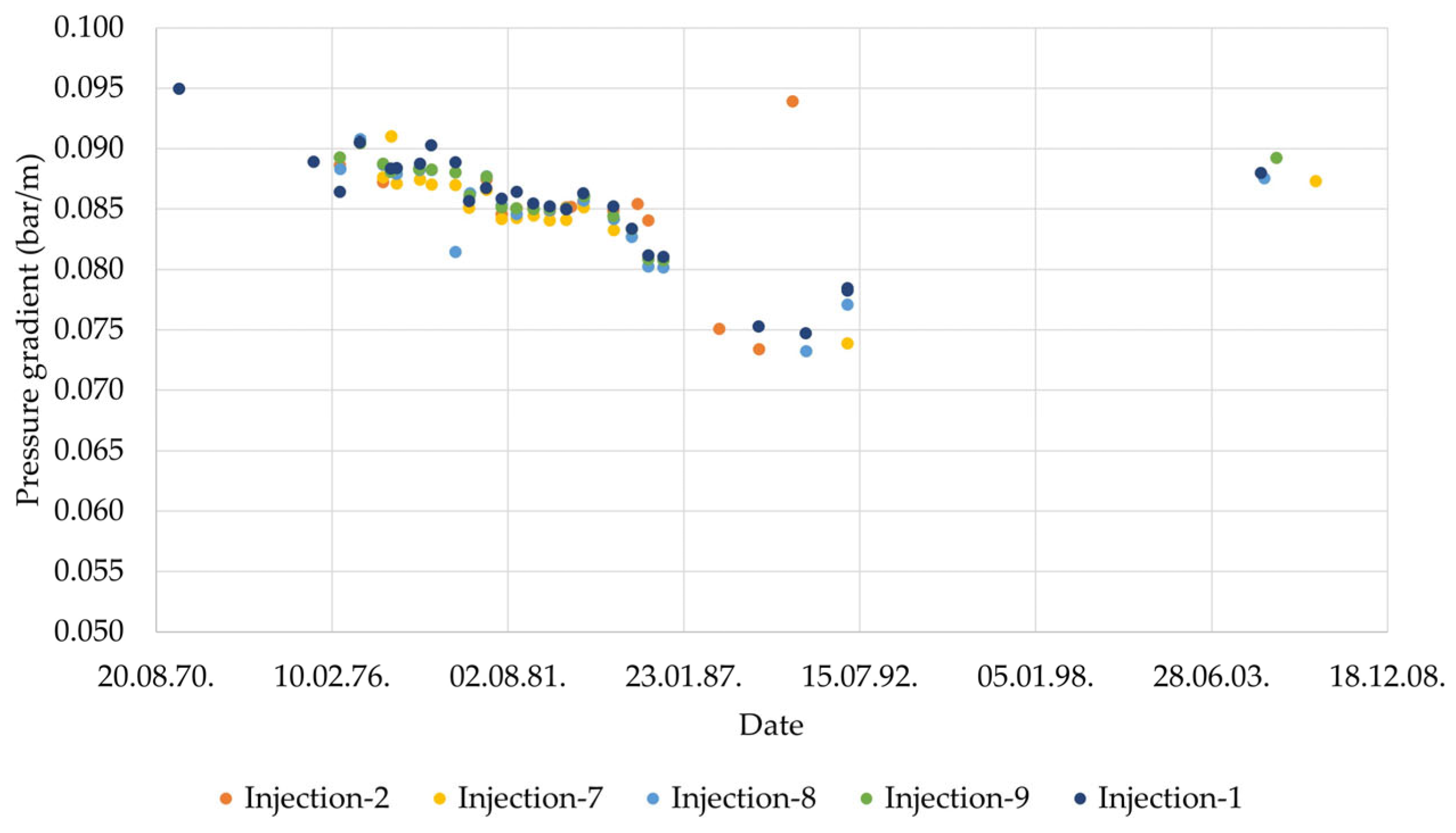
In the course of production, after a significant pressure drop and the occurrence of water in the oil production, the aquifer was confirmed, and in order to keep the pressure above the saturation pressure, water flooding was started three years after the start of production with the aim of keeping the reservoir pressure above the saturation pressure of 147 bar. In the absence of data on more recent measurements of static pressure, measurements of the injection wells below the oil–water contact level were analysed (Figure 4). Analysis of the measurements from 2005 and 2006, when the water injection system had already been established for more than 30 years, showed that the pressures at the analysed wells already approached the pressures originally measured at these wells during this period. Since the amount of produced and injected fluid was almost the same, an initial pressure gradient of 0.0961 bar/m was assumed in the analysis [54,57].
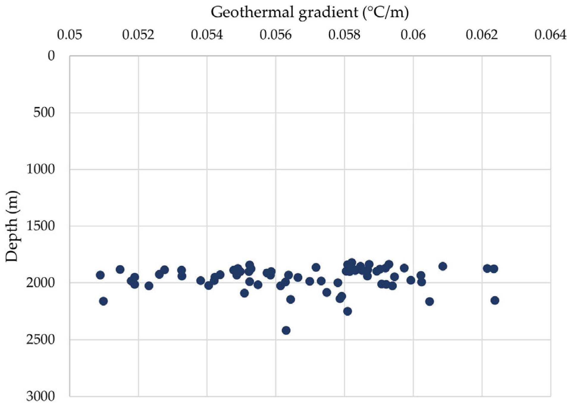
To estimate the temperature at the bottom of the reservoir, the geothermal gradient at the bottom of all wells drilled in the oil field was calculated (Figure 5). The average value of the geothermal gradient was 0.0567 °C/m. For the calculation of the geothermal gradient at the depth of the reservoir, an average ambient temperature of 11.09 °C was used, which corresponds to the average temperature for Osijek, the nearest town to the field, for the period of 1899–2021 [58]. During exploitation, the oil–water contact was found to be at −1.955 m, and during exploitation it was assumed that the contact was increased, resulting in a large number of wells being waterflooded and eventually excluded from production. For the analysis of the possibility of using the oil aquifer for geothermal energy production, the geothermal reservoir was assumed to be at −1955 m and the thickness of the geothermal reservoir was determined for each well from −1955 m to the depth reached by the well. The thickness of the geothermal reservoir at each well ranged from 10 m to over 600 m. It was assumed that the entire interval did not participate in the production, but rather a proportion of 70% per individual well, and in this way, the net reservoir thickness of the reservoir participating in the production of geothermal water was determined. The data used for the characterisation of the geothermal reservoir are listed in Table 1, using the net reservoir thicknesses with an average height of 95.4 m as the baseline values.
Based on the data of the average values, the Heat in Place of the geothermal aquifer of the analysed oil field was calculated, which was 1.15 × 10¹⁸ J.

2.5. Geothermal Brine Flow through Existing Well Completion

The main challenge in the commercial exploitation of geothermal energy from an existing oil field, i.e., through equipment on an existing oil field, is the constraint imposed by the existing well equipment. Namely, in order to reduce the cost of using geothermal energy while utilising abandoned oil wells, it is necessary to conduct an analysis of the existing equipment. The wells in the studied oil field were equipped for oil production and all wells had production intervals covered with 5″ to 5 ½″ casing, and production was achieved through 2 7/8″ tubing. For the purpose of geothermal water production, the tubing was neglected and production from the casing was assumed. When designing a geothermal field, one is interested in obtaining the highest possible flow. This is achieved by drilling open holes or slotted liners with larger dimensions in the production interval. The objective of this analysis was to explore the possibility of using abandoned oil wells within the framework of existing well completion. Typical well completion is presented in Figure 6 and was used for further brine flow analysis.

3. Results and Discussion

The analysis was conducted with a focus on reservoir conditions and the well’s production capability under constrained conditions:
  • the thickness of the geothermal reservoir accessed by a single well;
  • the permeability of the reservoir;
  • the gas–liquid ratio of the aquifer.
In this way, the possibility of using the existing infrastructure was analysed and the link with the economic viability of producing geothermal energy from the existing wells through the existing infrastructure was determined, i.e., how individual wells should be selected for the production of geothermal energy.

3.1. Permeability Probability Distribution

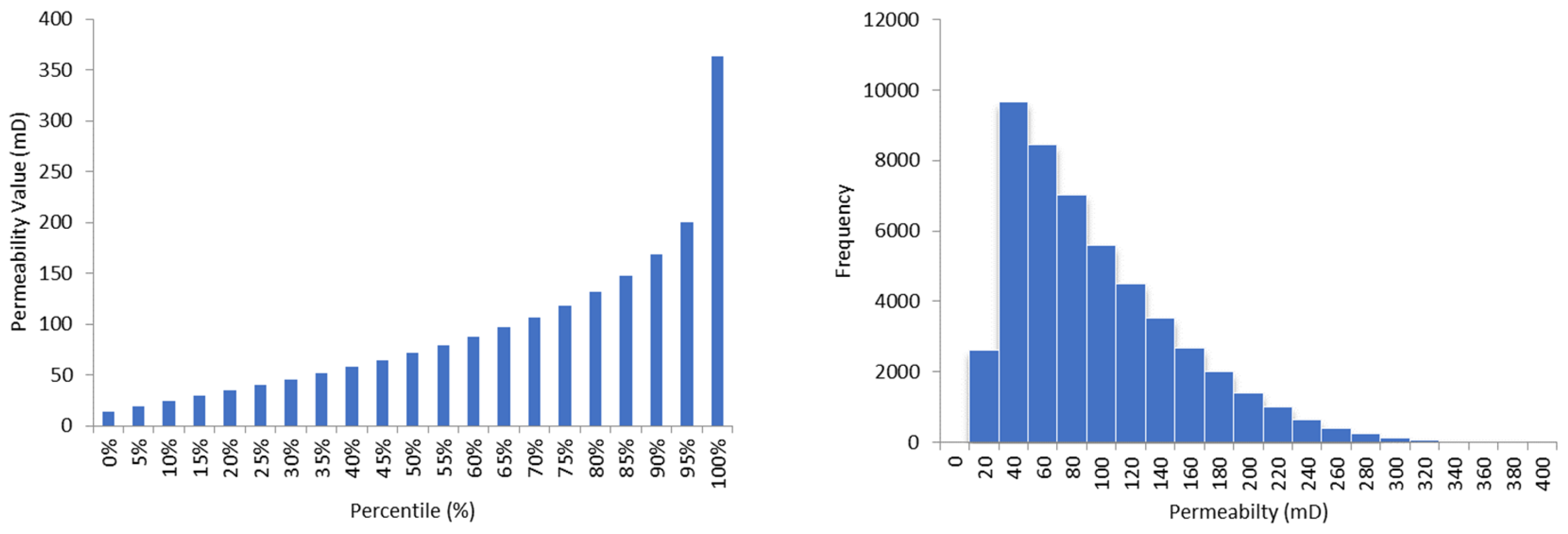
A Monte Carlo modelling of the permeability values was carried out to determine the possibility of extraction from a single well. A Beta-PERT distribution (PERT) was created to model the value of the permeability distribution, and to determine the most likely values and obtain a distribution that resembles the real permeability probability distribution. The PERT distribution highlights the most likely values relative to the minimum and maximum estimates and constructs a smooth version of the uniform or triangular distribution. The model was constructed with 50,000 iterations. Since there is no measurement of permeability in the geothermal reservoir itself under the current reservoir conditions, this is how the risk distribution was constructed when selecting a well for geothermal energy extraction. The permeability values were measured using Drill Steam Testing (DST) measurements performed during the drilling of 21 wells in an oil field (Figure 7). Since the geothermal reservoir belongs to the same reservoir as the oil reservoir, only in the water-saturated part, the values were modelled in order to obtain risk-adjusted values for the modelling of the geothermal reservoir. During the development of the oil field, several observations of the occurrence of fractures in the reservoir were recorded in the daily reports of the wells, so we can assume that an extremely increased permeability due to fractures could also occur in a single well (Table 2 and Figure 8). For the purposes of the Monte Carlo modelling, values with a high permeability of over 400 mD were excluded on the assumption that they belonged to the flow achieved through the reservoir fractures.

3.2. Sensitivity Analysis of Brine Flow Considering Well Completion Constraints

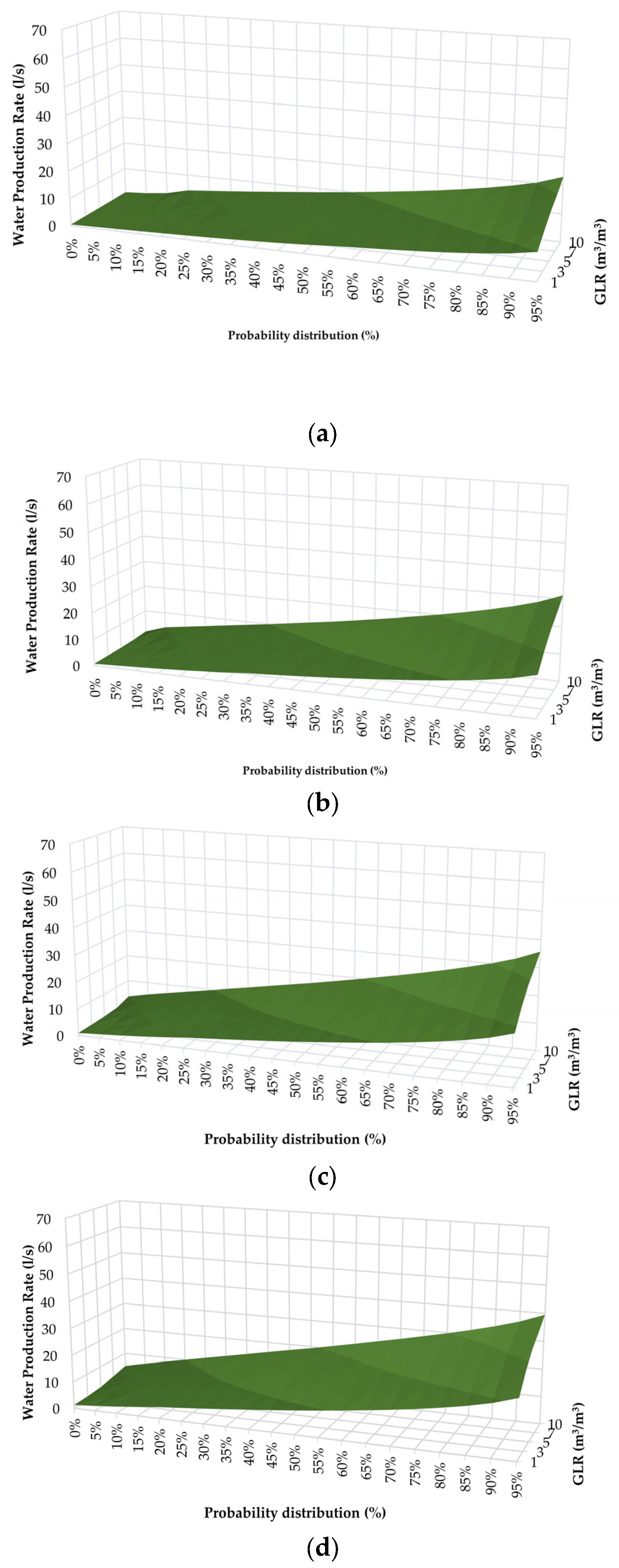
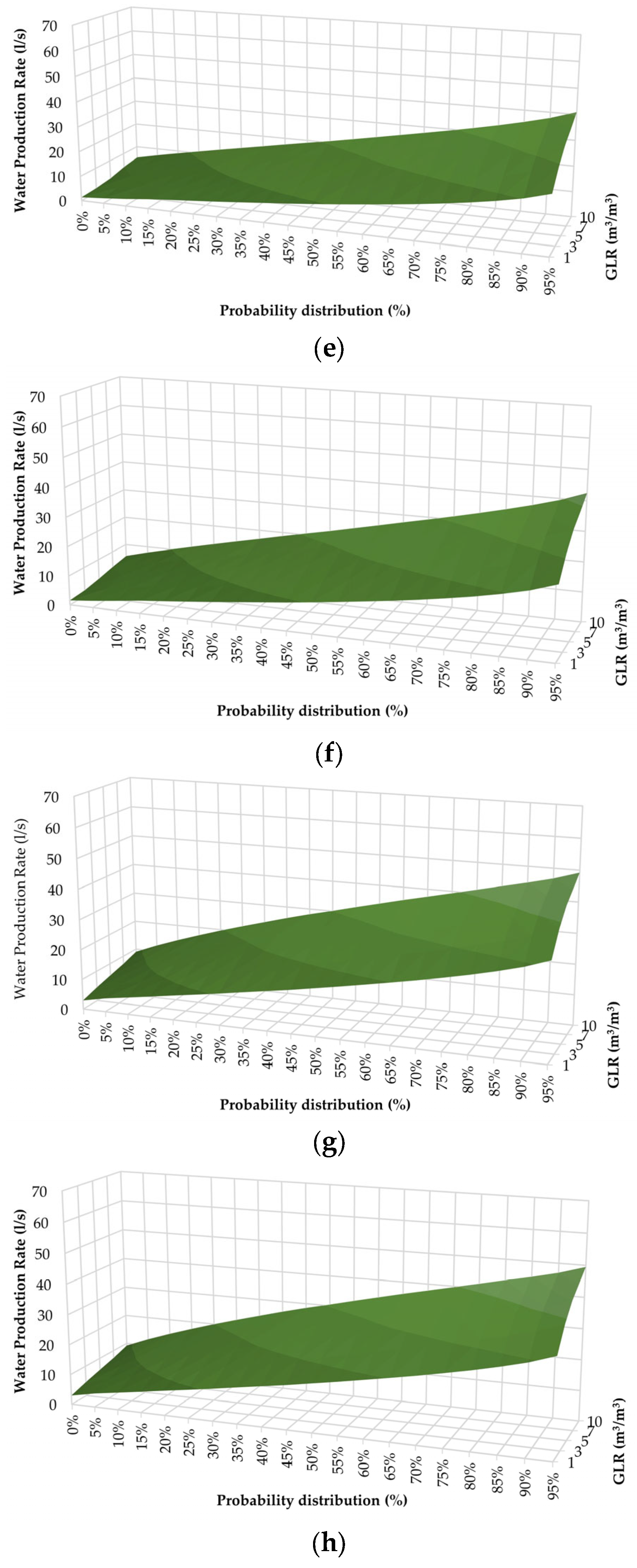
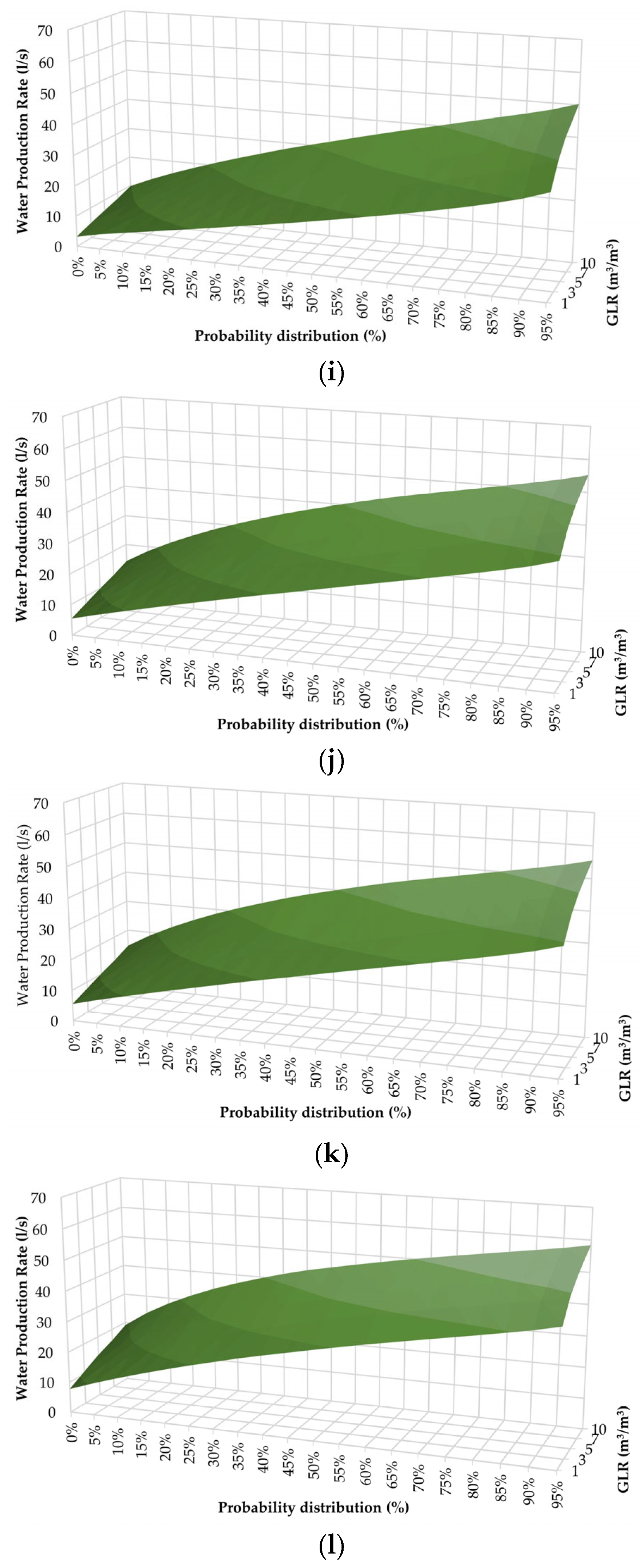
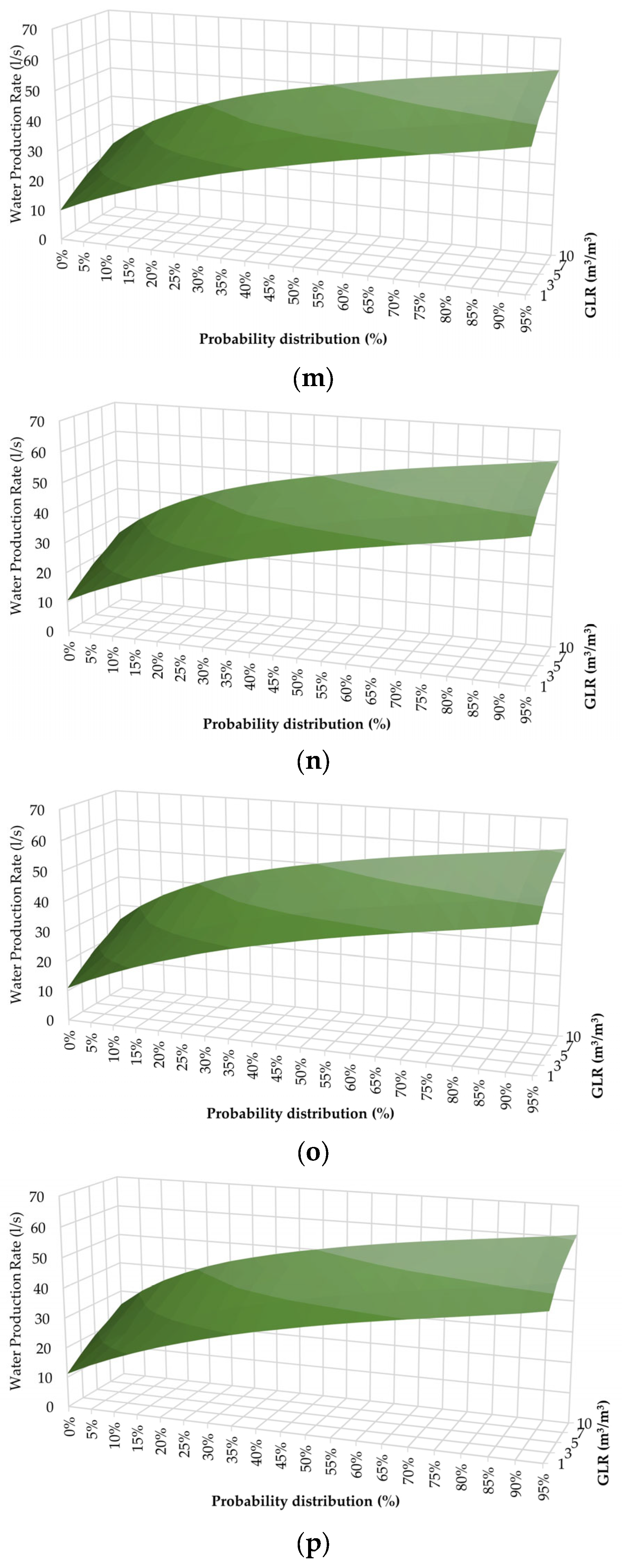
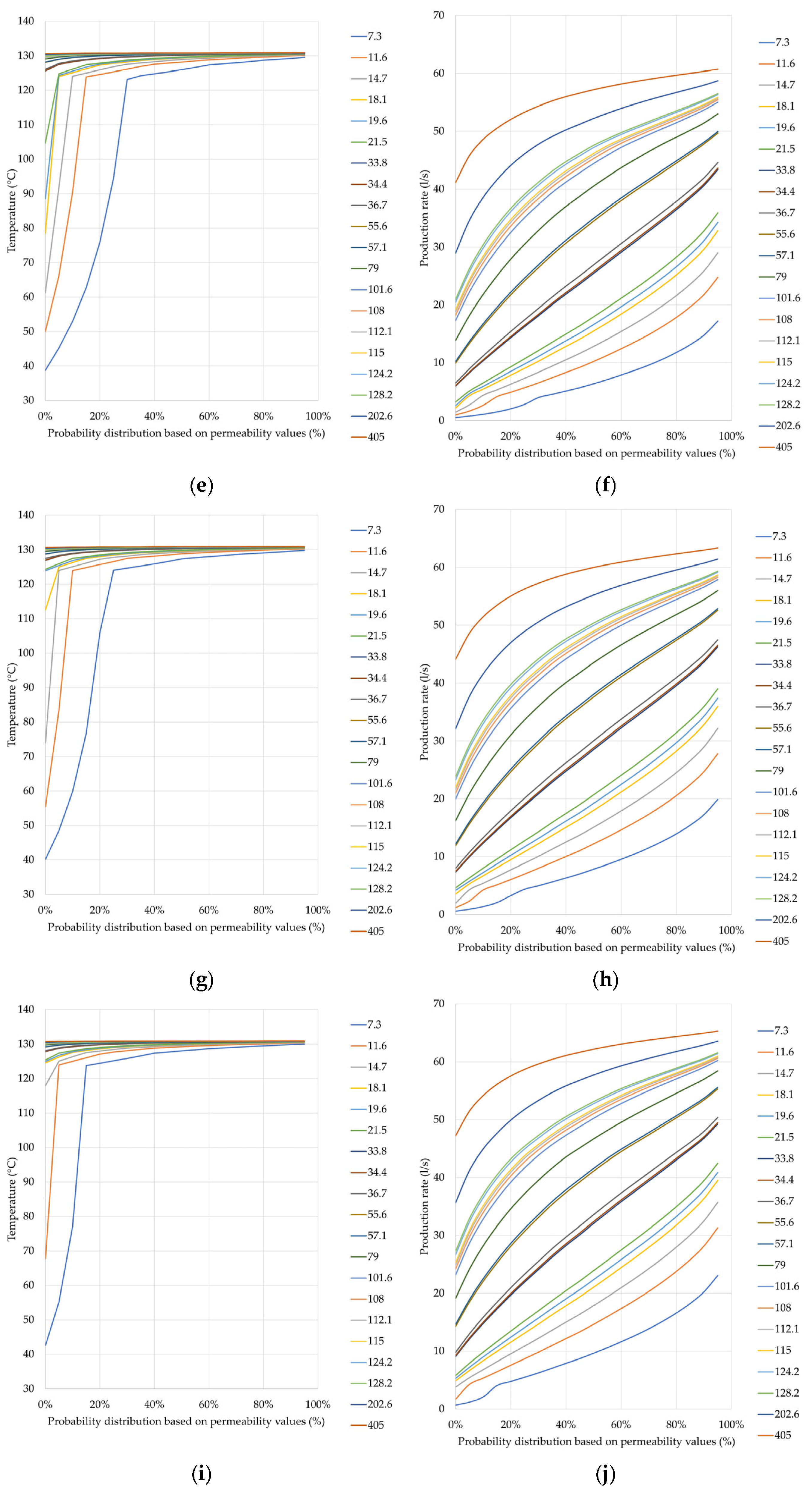
In view of the completion of the wells, the production possibilities of each reservoir in terms of thickness and permeability distribution were analysed in such a way that the sensitivity to the potential benefit and possibility of geothermal energy production per individual well was made in the PROSPER software package [59]. PROSPER is a programme used to optimise wells in the oil industry. This time, the production of brine was adjusted to assume a 99.99% water cut. The programme is used for different configurations of wells to predict flow under reservoir conditions. For the analysis, the characteristics of the oil field geothermal reservoir were used and the values affecting the well productivity were varied. For the equipment, a typical oil well in the field was taken, equipped with 5 1/2″ casing, and the production through the casing was preset. The thickness of the reservoir as a sensitivity parameter for the selection of the wells, i.e., wells that drilled the geothermal aquifer, is important for the selection of future wells in terms of the influence of thickness on flow and temperature [60]. The determination of the heat transfer coefficient is based on empirical data, and its evaluation in the modelling of the future geothermal reservoir is a variable that influences the evaluation [61,62]. In the case of a geothermal system, the determination of the heat transfer coefficient includes the convective heat transfer from the surrounding rock and heat loss via conduction. The heat transfer in the formation depends on the distribution of heat in the formation, the resistance to heat transfer in the well (casing) and the temperature differences [63]. To estimate the value of the heat transfer between the casing and the well and accordingly stabilise the temperature during geothermal extraction, the heat transfer coefficient was calculated with the module PROSPER Enthalpy Balance. The module takes into account heat transfer via conduction, radiation, and forced and free convection. The heat transfer coefficient was calculated using thermodynamic data stored in a user-defined database. The temperature predictions were transient, attributing sensitivity to the flow time of the wells. Using the module, the lithology was described and the production data obtained by modelling the flow through the well were tested, and the heat transfer coefficient for the well was determined using the modelled data. Since the geothermal reservoir is in carbonates, it was assumed that there was a dissolved gas in the reservoir, mainly CO2. The assumption that CO2 is present in carbonate reservoirs results from the thermal decomposition of the carbonates, resulting in CO2 presence [64], which is confirmed by data from other geothermal reservoirs [65]. Assuming the presence of CO2 in the reservoir, the sensitivity to dissolved CO2 in the brine was modelled in amounts of 1, 3, 5, 7 and 10 m3/m3 (Figure 9a–t).
The influence of dissolved gas in the brine is the factor with the greatest uncertainty when it is at a measurement of 1 m3/m3 and the risk of low permeability distribution in the well is at 50% (Figure 10). The dissolved gas affects the flow rate and, accordingly, the heat transfer in the well, leading to the rejection of wells with poor permeability characteristics due to low flow rates. Reservoir thickness is a limiting factor in achieving stable wellhead temperature and, accordingly, a risk factor in selecting wells for future geothermal brine production. Temperature stabilisation begins with reservoirs whose thickness exceeds 55 m.

3.3. Assessment of the Techno-Economic Potential on a Well Basis

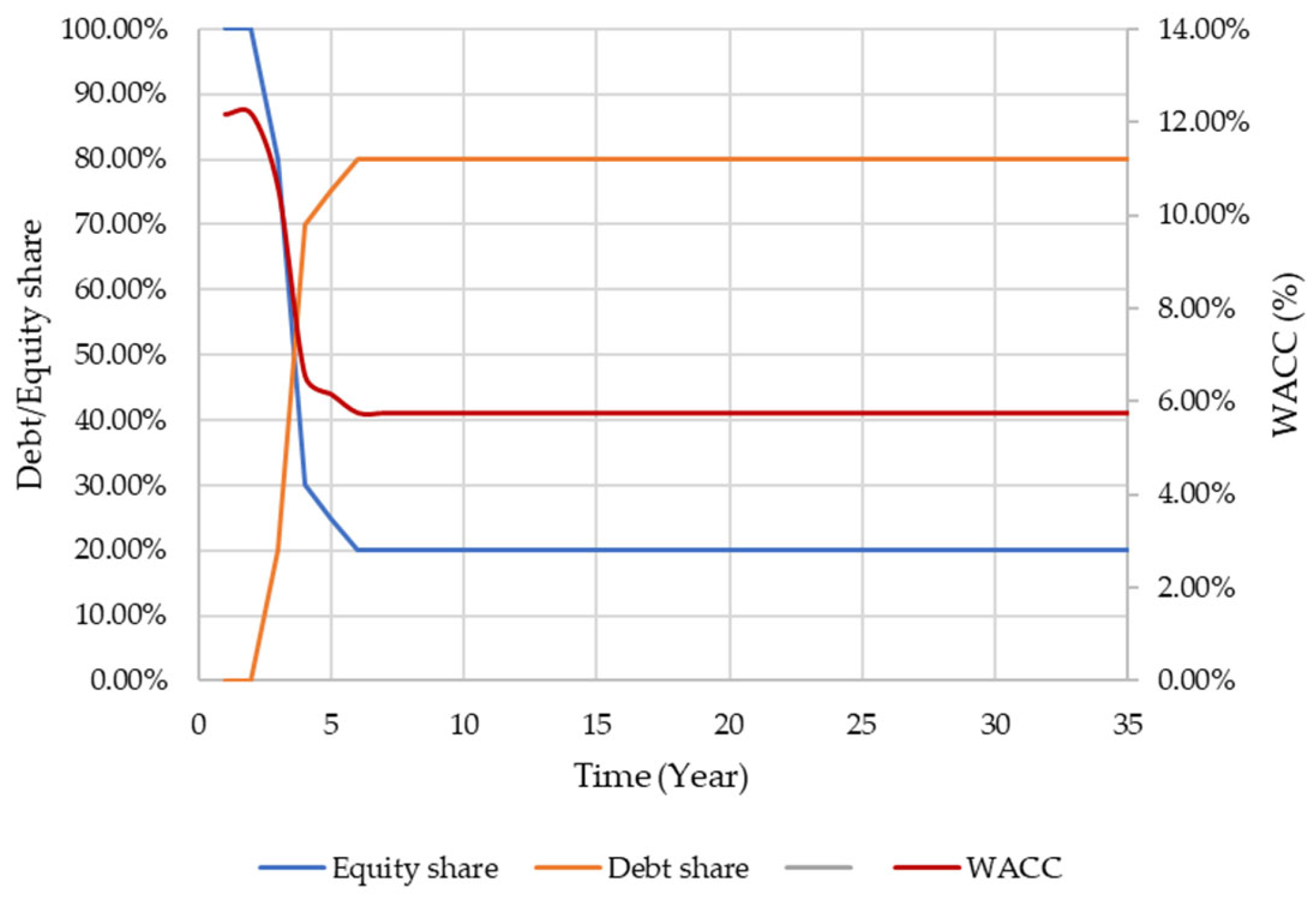
In order to make a selection of wells suitable for the future production of geothermal energy, it is necessary to determine economic parameters that meet economically acceptable criteria. The creation of an economic model of one well is a conservative approach to selection and as such represents a lower risk for future production from several selected wells, together, of course, with a macroeconomic analysis of the economic acceptability of production from the entire field. To determine the output that a single well can produce at a given wellhead temperature and flow rate, the open-source geothermal techno-economic simulator GEOPHIRES v2.0 was used [66]. The programme is used to calculate the current energy production and lifetime energy production, as well as the total levelized energy costs of a geothermal system. It combines reservoir, well and surface plant models, as well as economic and cost models and correlations, to estimate capital costs as well as operation and maintenance costs. The capital and operating costs for the different components of a geothermal system (exploration, well, surface plant) are calculated using integrated correlations. The programme has six possible models built in. For the calculation of power and costs at the level of a single well, a model is used that assumes a hydrothermal reservoir and subcritical ORC power generation. For the calculation of the potential output power, the values for temperature and flow, determined via the sensitivity analysis, were used, while for the economic analysis, the values for the capital and operating costs were used, and the costs of creating new wells were ignored. Considering the proposed cost of capital, the WACC was calculated based on the assumption of dynamic equity and the debt ratio [67,68]. Namely, it was assumed that in the initial phase, due to the high risk of achieving positive effects of the project, the share of equity was 100%, and that, over time, the share of equity would decrease in favour of debt. According to the CAPM method, the ratio of debt to equity affects the final WACC value. For the economic analysis, an average WACC value of 6.30% over 30 years of geothermal energy production was assumed (Figure 11).
The economic analysis determined the range of the possible values of the energy produced and the NPV of a single well. The economically acceptable threshold was determined to be the value of energy produced by a single well that first achieved a positive NPV (Table 3). In this way, the value of the least acceptable produced energy per single well was determined, which was 0.44 MW for a flow rate of 20 L/s and a wellhead temperature of 130 °C (Figure 12).
Based on the limit of the economic viability of geothermal energy production per well, a limit was established for the acceptable values of flow rate and well temperature, at which an energy production of 0.44 MW or more was achieved. In this way, a matrix of values for different amounts of dissolved gas and brine was created [69]. Based on the minimum economic viability per well, a project success/failure curve was created, i.e., the temperature and flow rate values at which sufficient performance was achieved for economic viability. The determination of the techno-economic conditions for the selection of wells for the production of geothermal energy involved the sensitivity analysis of the flow rate and temperature achieved, which correspond to the economic cut-off at 50% risk conditions, using the permeability distribution as a risk factor. The sensitivity analysis made it possible to determine the economic profitability of each option under the conditions of different GLRs that can be achieved in the reservoir. Considering the risk distribution as a function of permeability, the conditions under which economic production per well is achieved and the risk is 50% at a gas–liquid ratio of 1 m3/m3 are only achieved in reservoirs with a net thickness greater than 55.6 m. As the gas–liquid ratio increases, this limit shifts to the net thickness of the reservoir of 36.7 m at a GLR of 3 m3/m3, and in a reservoir with a thickness of less than 21.5 m, there are conditions where the techno-economic conditions for selecting a well are not met even at a GLR of 10 m3/m3. From the distribution of the risks for the production of geothermal energy, it can be concluded that the wells whose thickness of the geothermal reservoir, i.e., the net thickness of the reservoir at a single well, is less than 55.6 m should be excluded from further analysis, as their consideration only includes extraction with a higher probability risk associated with the permeability distribution. In this way, a uniform risk in the production of geothermal energy is ensured for all cases of dissolved gas in the brine. Figure 13 shows the achieved ratios of flow and temperature at the wellhead, at different GLR ratios, simulated using PROSPER in relation to the limit of acceptability of these ratios in relation to the success/failure curve modelled via the sensitivity analysis of the economic parameters. For the further analysis of acceptable wells for geothermal production, the thickness of the reservoir was set to a minimum of 55 m.

3.4. Reservoir Simulation

A simulation model was created to provide insight into the total energy produced throughout the field by applying the model of individual well selection based on techno-economic characteristics. Furthermore, the model provided insight into the possibilities of interaction, i.e., the additional selection of wells with regard to their existing location. The TOUGH2 simulator was used to create the model. TOUGH2 is a numerical simulator for non-isothermal flows of multicomponent, multiphase fluids in one-, two- and three-dimensional porous and fractured media [70]. TOUGH2-EOS1 was used for the modelling as the simple geological modelling was approached via Petrasim, an auxiliary tool when using TOUGH2, as the analysis did not include the detailed geological modelling of the field or the detailed distribution of the reservoir properties.
The algorithmic model covered the entire area of about 50 km2. A polygonal grid was used to model the grid block, with cells of a maximum size of 1 × 10⁵ m2 and a refinement around the wells of 5000 m2. According to the geological setting of the field, the model was divided into seven layers corresponding to seven lithological units, each with physical rock properties corresponding to the lithological unit and the depth of the unit. The rock density values were determined via correlation for the Drava Depression [71,72], and based on this, the heat conductivity and specific heat were determined for each layer, i.e., the bed of the model. The parameters were evenly distributed across each layer.
The initial conditions for the model were based on the initial conditions of the oil field (Table 1), where the geothermal gradient was determined as 0.0567 °C/m and the pressure gradient as −0.0961 bar/m. The upper pressure limit was set at 2 bar, which corresponded to the well flow analysis, while the top boundary temperature was set at 11.09 °C [58]. The geothermal reservoir was defined from the oil–water contact at an absolute depth of 1955 m to a final depth of 2850 m. By analysing the behaviour of the temperature inside the observed geothermal reservoir when applying the geothermal gradient, it was shown that the temperature inside the reservoir varies due to the large difference in the depth of the reservoir in the simulated model. Assuming convection conditions within the geothermal reservoir, and in order to bring the results closer to the conditions simulated via the well flow analysis, a constant temperature of 135.78 °C was assumed in the geothermal reservoir, which was determined as the mean temperature of the geothermal reservoir. The permeability of the geothermal reservoir was 71.62 mD, which corresponded to the sensitivity analysis of permeability, with a probability of 50%. The bottom boundary was defined with a constant temperature of 141.7 °C, the highest temperature measured at the bottom of the well at a depth of 2956 m. The simulation time was set to 30 years.
The numerical simulation of a geothermal reservoir is an essential element of the assessment of geothermal potential and involves numerous parameters that define thermodynamic and hydrodynamic relationships [73,74,75,76]. Due to the simplicity of the model, some of the parameters in the model were ignored and the model was a simplified version of the geothermal potential of a whole field based on a techno-economic well selection. The aim of the numerical simulation was to study the production from the geothermal reservoir using data obtained through the techno-economic analytical modelling, applying the results of the permeability distribution corresponding to the 50% risk distribution. Since the techno-economic analysis concluded that, with a risk distribution of 50%, wells should be taken where the net thickness of the geothermal reservoir is more than 55 m, 12 of the total 22 wells analysed met the techno-economic conditions for inclusion in the field model. After building the model and analysing the well locations, two production wells (monitoring wells) were excluded from the model because they were located near wells whose depth of penetration into the reservoir and thus production characteristics were more favourable. Given the conditions, two scenarios were created in which the injection parameters were varied. In Scenario 1, ten wells were involved as production wells with a total production of 387.49 L/s, while seven wells were involved as injection wells, and the injection was evenly distributed among the wells and was 55.35 L/s per well, while the enthalpy of the injected brine corresponded to a temperature of 60 °C. The injection wells have open perforations for injection from the shallowest depth of 1975 m to the deepest depth reached by the well, which is −2460 m. To analyse the impact of injection on the total potentially recoverable energy, Scenario 2 simulated production with 10 production wells at the same production rate as Scenario 1, but the injection was simulated through four wells and the injected brine was simulated to the deeper parts of the reservoir. In this way, the shallowest injection well was set to a depth of −2199 m.
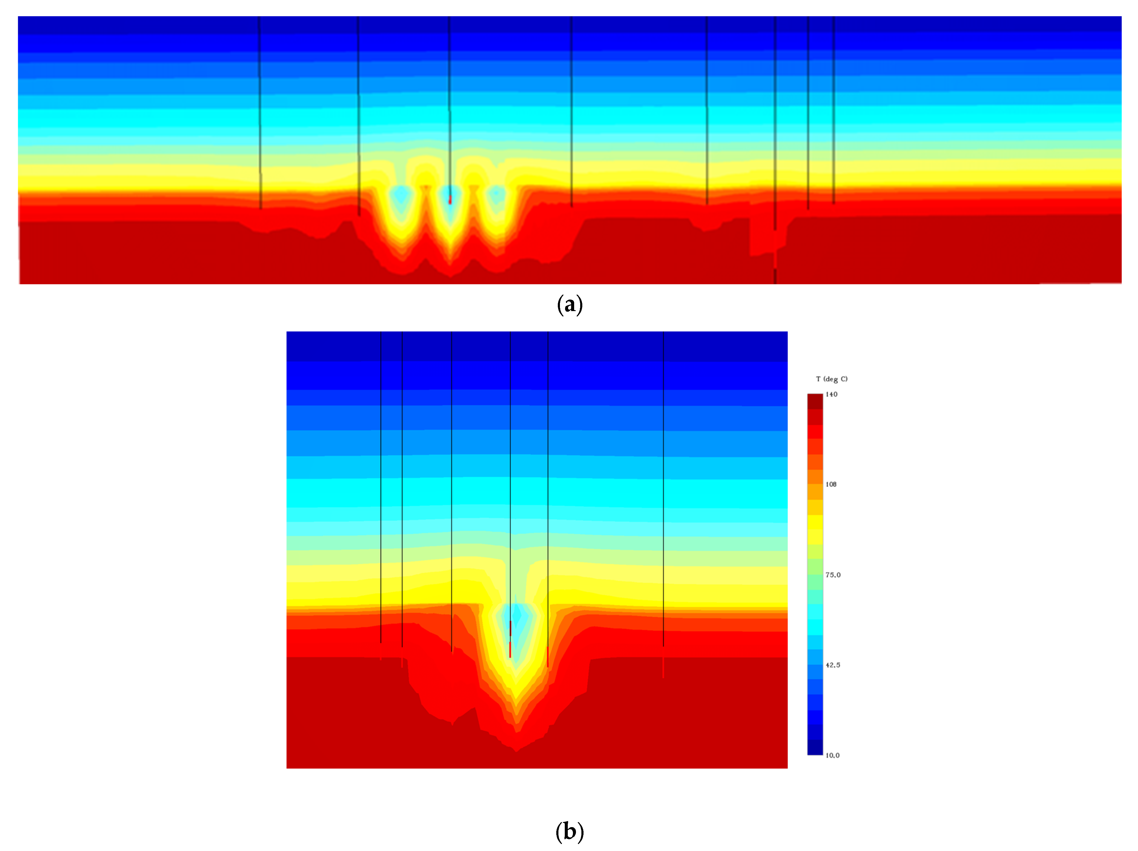
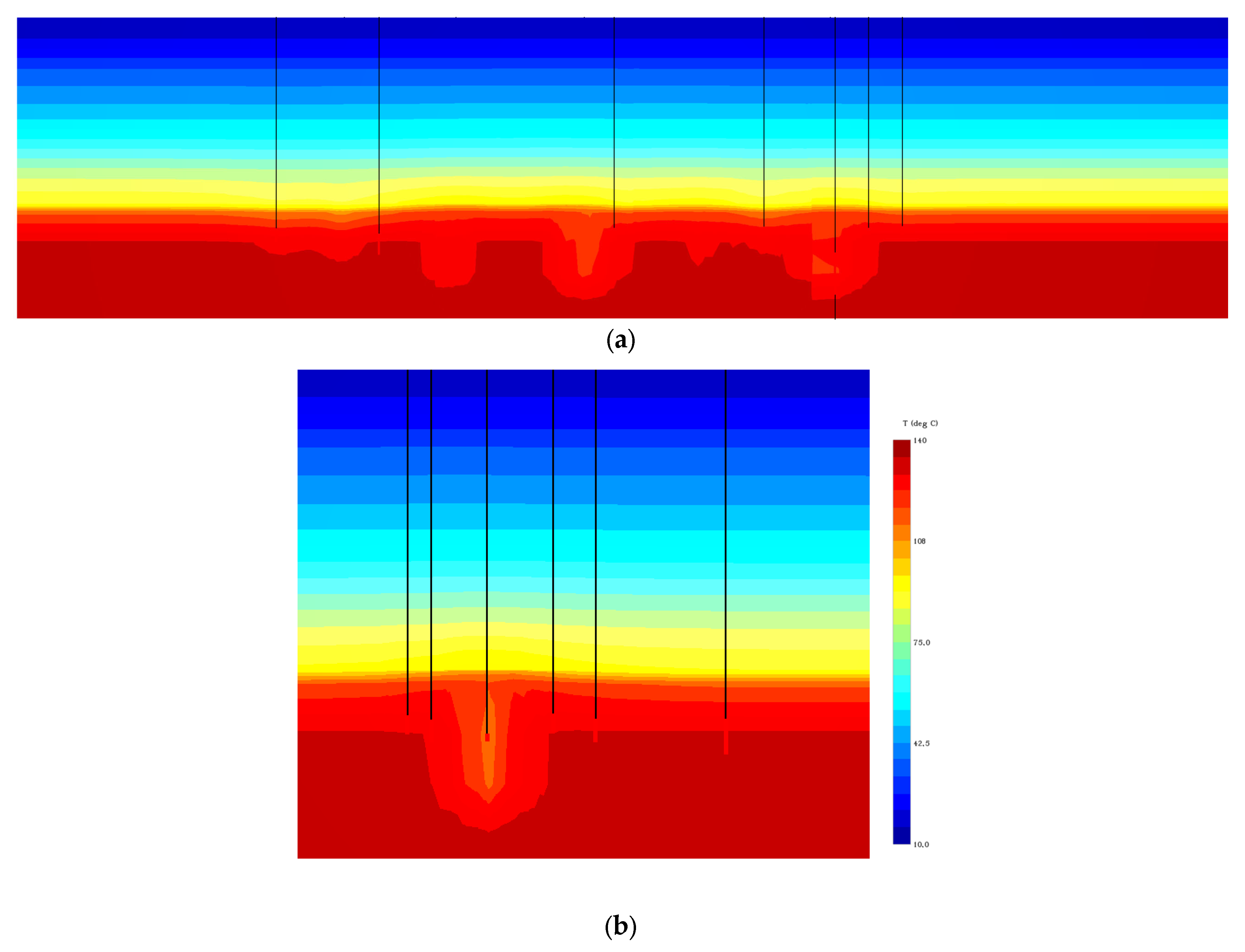
The simulation of the reservoir conditions in Scenario 1 showed that the cold front intrusion covered a larger part of the reservoir (Figure 14a,b), while the total field energy in the first year of production was 230.011 × 10⁶ J/s, while the field energy decreased to 221.346 × 10⁶ J/s after 30 years of production. In Scenario 2, which simulated water intrusion into the deeper part of the reservoir through fewer wells, the cold front intrusion covered a smaller part of the reservoir, i.e., the distribution of the cold front was less dominant around the injection wells themselves. The distribution of the cold front had an impact on the total energy of the field. The first year of production resulted in the same field energy as Scenario 1, while the total energy after 30 years of production was 221.456 × 10⁶ J/s (Figure 15a,b). The comparison of Scenarios 1 and 2 shows that the total energy of the reservoir is influenced by the injection depth, notwithstanding the fact that, in Scenario 2, a higher flow through the injection wells had to be simulated. Furthermore, the energy potential of the reservoir decreased by 3.767% in Scenario 1, while the energy in Scenario 2 decreased by 3.719% over a period of 30 years, which in total influence the economic viability of the geothermal potential.

4. Conclusions

The conversion of oil fields into geothermal energy is a topic of great interest and therefore attracts much attention. The knowledge acquired in the exploration and exploitation of hydrocarbons, and especially the infrastructure, become valuable assets in the use of geothermal energy. Since conversion mainly involves low- and medium-enthalpy geothermal aquifers, the available resources must be optimally utilised. When we talk about the conversion of hydrocarbon fields into geothermal energy, a clear plan to analyse numerous parameters is required to maximise the production of geothermal energy. Apart from the condition of the reservoir, i.e., the parameters of pressure, permeability, porosity and temperature, the completion of the wells is one of the main difficulties in converting oil wells into geothermal energy wells. When analysing the technical conditions that enable the flow, it was concluded that the reservoir cannot develop its full potential due to the limitations in the well completion, so due attention must be paid to the modelling of the reservoir, that is, the net thickness of the reservoir that will participate in the future production of geothermal brine. Therefore, for low- to medium-enthalpy geothermal reservoirs such as those presented in this paper, the focus of the analysis must be on the potential flow through the casing. Flow, in addition to well temperature, affects the economic valuation of a project, because if flow increases by only 5%, geothermal production through a single well increases by 6.82%, so the well reaches an economic cut-off, i.e., the conversion of oil in the well receives its economic value. Besides the individual analysis of each well and the selection of the best candidates, only the simulation of the geothermal production of the whole field provides information about the interaction of production and injection wells, and the energy potential of the reservoir. The conversion of oil fields to geothermal fields is a complex problem, both in terms of reservoir parameters and well completion, and in terms of the overall economic effect of the whole field, which is influenced by the behaviour of the reservoir in terms of well doublet placement and the possibility of reaching more favourable parts of the reservoir. The economic analysis for the whole field should be confronted with the analysis of the costs of abandoning the oil field and reducing CO2 emissions. Only in this respect would the profitability of the project be comparable to the benefits of the transformation. Therefore, further studies should be conducted to assess the contribution of such transformations to the green transition.

Author Contributions

Conceptualization: M.T.; methodology: M.T. and T.K.; simulations: M.T.; validation: T.K.; writing—original draft and review: M.T. and T.K.; supervision: T.K.; investigation: M.T. All authors have read and agreed to the published version of the manuscript.

Funding

The APC was partially funded by the European Commission’s Interreg CENTRAL EUROPE programme (project TRANSGEO, grant number CE0100071) and partially by the Development fund of the Faculty of Mining, Geology and Petroleum Engineering, Zagreb, Croatia.

Data Availability Statement

All data used in the analysis are the property of the Republic of Croatia and were obtained from the database of the Croatian Hydrocarbon Agency, and may be used for scientific research purposes.

Acknowledgments

The Faculty of Mining, Geology and Petroleum Engineering, University of Zagreb, Croatia, facilitated the use of the software package PROSPER, while the Croatian Hydrocarbon Agency facilitated the use of the software package TOUGH2.

Conflicts of Interest

The authors declare no conflict of interest.

References

  1. IRENA. Renewable Capacity Statistics 2023; International Renewable Energy Agency: Abu Dhabi, United Arab Emirates, 2023. [Google Scholar]
  2. Sveinbjornsson, B.M.; Thorhallsson, S. Cost and effectiveness of geothermal drilling. In Proceedings of the SIMS 53rd Conference, Reykjavik, Iceland, 4–6 October 2012. [Google Scholar]
  3. Augustine, C.; Tester, J.W.; Anderson, B. A Comparison of Geothermal with Oil and Gas Well Drilling Costs. In Proceedings of the Thirty-First Workshop on Geothermal Reservoir Engineering, Stanford University, Stanford, CA, USA, 30 January–1 February 2006. [Google Scholar]
  4. Lukawski, M.Z.; Anderson, B.J.; Augustine, C.; Capuano, L.; Beckers, K.F.; Livesay, B.; Tester, J.W. Cost Analysis of Oil, Gas, and Geothermal Well Drilling. J. Pet. Sci. Eng. 2014, 118, 1–14. [Google Scholar] [CrossRef]
  5. Kaplanoğlu, M.A.; Baba, A.; Akkurt, G.G. Use of Abandoned Oil Wells in Geothermal Systems in Turkey. Geomech. Geophys. Geo-Energy Geo-Resour. 2019, 6, 1. [Google Scholar] [CrossRef]
  6. Wang, S.; Yan, J.; Li, F.; Hu, J.; Li, K. Exploitation and Utilization of Oilfield Geothermal Resources in China. Energies 2016, 9, 798. [Google Scholar] [CrossRef]
  7. Leitch, A.L.; Haley, B.; Hastings-Simon, S. Can the Oil and Gas Sector Enable Geothermal Technologies? Socio-Technical Opportunities and Complementarity Failures in Alberta, Canada. Energy Policy 2019, 125, 384–395. [Google Scholar] [CrossRef]
  8. Nadkarni, K.; Lefsrud, L.; Schiffner, D.; Banks, J. Converting Oil Wells to Geothermal Resources: Roadmaps and Roadblocks for Energy Transformation. Energy Policy 2022, 161, 112705. [Google Scholar] [CrossRef]
  9. Mahmoodpour, S.; Singh, M.; Mahyapour, R.; Tangirala, S.K.; Bär, K.; Sass, I. Numerical Simulation of Thermo-Hydro-Mechanical Processes at Soultz-Sous-Forêts. Energies 2022, 15, 9285. [Google Scholar] [CrossRef]
  10. Singh, M.; Mahmoodpour, S.; Ershadnia, R.; Soltanian, M.R.; Sass, I. Comparative Study on Heat Extraction from Soultz-Sous-Forêts Geothermal Field Using Supercritical Carbon Dioxide and Water as the Working Fluid. Energy 2023, 266, 126388. [Google Scholar] [CrossRef]
  11. Fridleifsson, I.B. Geothermal Energy for the Benefit of the People. Renew. Sustain. Energy Rev. 2001, 5, 299–312. [Google Scholar] [CrossRef]
  12. Lund, J.W.; Toth, A.N. Direct utilization of Geothermal Energy 2020 Worldwide Review. In Proceedings of the World Geothermal Congress 2020+1, Reykjavik, Iceland, 24–27 October 2021. [Google Scholar]
  13. Di Pippo, R. Geothermal Power Plants, Principles, Applications, Case Studies and Environmental Impact. Elements of Thermodynamics; Butterworth-Heinemann: Waltham, MA, USA, 2016; pp. 715–726. [Google Scholar] [CrossRef]
  14. Lindal, B. Industrial and other applications of geothermal energy. In Geothermal Energy; UNESCO: New York, NY, USA, 1973; pp. 135–148. [Google Scholar]
  15. Hranić, J.; Raos, S.; Leoutre, E.; Rajšl, I. Two-Stage Geothermal Well Clustering for Oil-to-Water Conversion on Mature Oil Fields. Geosciences 2021, 11, 470. [Google Scholar] [CrossRef]
  16. Kurnia, J.C.; Shatri, M.S.; Putra, Z.A.; Zaini, J.; Caesarendra, W.; Sasmito, A.P. Geothermal Energy Extraction Using Abandoned Oil and Gas Wells: Techno-Economicand Policy Review. Int. J. Energy Res. 2021, 46, 28–60. [Google Scholar] [CrossRef]
  17. Westphal, D.; Weijermars, R. Economic Appraisal and Scoping of Geothermal Energy Extraction Projects Using Depleted Hydrocarbon Wells. Energy Strategy Rev. 2018, 22, 348–364. [Google Scholar] [CrossRef]
  18. Li, K.; Sun, W. Modified Method for Estimating Geothermal Resources in Oil and Gas Reservoirs. Math. Geosci. 2014, 47, 105–117. [Google Scholar] [CrossRef]
  19. Nian, Y.-L.; Cheng, W.-L. Insights into Geothermal Utilization of Abandoned Oil and Gas Wells. Renew. Sustain. Energy Rev. 2018, 87, 44–60. [Google Scholar] [CrossRef]
  20. Wang, K.; Yuan, B.; Ji, G.; Wu, X. A Comprehensive Review of Geothermal Energy Extraction and Utilization in Oilfields. J. Pet. Sci. Eng. 2018, 168, 465–477. [Google Scholar] [CrossRef]
  21. Caulk, R.; Tomac, I. Reuse of Abandoned Oil and Gas Wells for Geothermal Energy Production. Renew. Energy 2017, 112, 388–397. [Google Scholar] [CrossRef]
  22. Macenić, M.; Kurevija, T. Revitalization of Abandoned Oil and Gas Wells for a Geothermal Heat Exploitation by Means of Closed Circulation: Case Study of the Deep Dry Well Pčelić-1. Interpretation 2018, 6, SB1–SB9. [Google Scholar] [CrossRef]
  23. Bu, X.; Ma, W.; Li, H. Geothermal Energy Production Utilizing Abandoned Oil and Gas Wells. Renew. Energy 2012, 41, 80–85. [Google Scholar] [CrossRef]
  24. Davis, A.; Michaelides, E.E. Geothermal Power Production from Abandoned Oil Wells. Energy 2009, 34, 866–872. [Google Scholar] [CrossRef]
  25. Gharibi, S.; Mortezazadeh, E.; Bodi, S.J.H.A.; Vatani, A. Feasibility Study of Geothermal Heat Extraction from Abandoned Oil Wells Using a U-Tube Heat Exchanger. Energy 2018, 153, 554–567. [Google Scholar] [CrossRef]
  26. Wang, K.; Liu, J.; Wu, X. Downhole Geothermal Power Generation in Oil and Gas Wells. Geothermics 2018, 76, 141–148. [Google Scholar] [CrossRef]
  27. Santos, L.; Taleghani, A.D.; Elsworth, D. Repurposing Abandoned Wells for Geothermal Energy: Current Status and Future Prospects. Renew. Energy 2022, 194, 1288–1302. [Google Scholar] [CrossRef]
  28. Liu, X.; Falcone, G.; Alimonti, C. A Systematic Study of Harnessing Low-Temperature Geothermal Energy from Oil and Gas Reservoirs. Energy 2018, 142, 346–355. [Google Scholar] [CrossRef]
  29. Dickson, M.H.; Fanelli, M. Small Geothermal Resources: A Review. Energy Sources 1994, 16, 349–376. [Google Scholar] [CrossRef]
  30. Lee, K.C. Classification of Geothermal Resources by Exergy. Geothermics 2001, 30, 431–442. [Google Scholar] [CrossRef]
  31. Rybach, L. Classification of Geothermal Resources by Potential. Geotherm. Energy Sci. 2015, 3, 13–17. [Google Scholar] [CrossRef]
  32. Muffler, P.; Cataldi, R. Methods for Regional Assessment of Geothermal Resources. Geothermics 1978, 7, 53–89. [Google Scholar] [CrossRef]
  33. Williams, C.F.; Reed, M.J.; Robert, H.M. A Review of Methods Applied by the U.S. Geological Survey in the Assessment of Identified Geothermal Resources; Open-File Report 2008–1296; U.S. Geological Survey: Reston, VA, USA, 2008; 30p. [Google Scholar]
  34. Muffler, L.J.P. Assesment of Geothermal Resources of the United States. Geol. Surv. Circ. 1978, 790, 163. [Google Scholar]
  35. Song, J.; Loo, P.; Teo, J.; Markides, C.N. Thermo-Economic Optimization of Organic Rankine Cycle (ORC) Systems for Geothermal Power Generation: A Comparative Study of System Configurations. Front. Energy Res. 2020, 8. [Google Scholar] [CrossRef]
  36. Astolfi, M.; Romano, M.C.; Bombarda, P.; Macchi, E. Binary ORC (Organic Rankine Cycles) Power Plants for the Exploitation of Medium–Low Temperature Geothermal Sources—Part A: Thermodynamic Optimization. Energy 2014, 66, 423–434. [Google Scholar] [CrossRef]
  37. DiPippo, R. Second Law Assessment of Binary Plants Generating Power from Low-Temperature Geothermal Fluids. Geothermics 2004, 33, 565–586. [Google Scholar] [CrossRef]
  38. Hijriawan, M.; Pambudi, N.A.; Biddinika, M.K.; Wijayanto, D.S.; Kuncoro, I.W.; Rudiyanto, B.; Wibowo, K.M. Organic Rankine Cycle (ORC) in Geothermal Power Plants. J. Phys. 2019, 1402, 044064. [Google Scholar] [CrossRef]
  39. Milora, S.L.; Tester, J.W. Geothermal Energy as a Source of Electric Power; MIT: New York, NY, USA, 1976; p. 186. [Google Scholar]
  40. Matanović, D. Cijevne Alatke pri Opremanju i Održavanju Bušotina (Tubulars in Completion and Workover Operations); Faculty of Mining, Geology and Petroleum Engineering, University of Zagreb: Zagreb, Croatia, 1999. [Google Scholar]
  41. Zarrouk, S.J.; McLean, K. Geothermal Wells. In Geothermal Well Test Analysis; Elsevier: London, UK, 2019; pp. 39–61. [Google Scholar] [CrossRef]
  42. Renpu, W. Well Completion Mode Selection. In Advanced Well Completion Engineering, 3rd ed.; Elsevier: Waltham, MA, USA, 2011; pp. 75–116. [Google Scholar] [CrossRef]
  43. Teodoriu, C.; Falcone, G. Comparing Completion Design in Hydrocarbon and Geothermal Wells: The Need to Evaluate the Integrity of Casing Connections Subject to Thermal Stresses. Geothermics 2009, 38, 238–246. [Google Scholar] [CrossRef]
  44. Kipsang, C. Cost Model for Geothermal Wells. In Proceedings of the World Geothermal Congress, Melbourne, Australia, 19–25 April 2015. [Google Scholar]
  45. Lukawski, M.Z.; Silverman, R.; Tester, J.W. Uncertainty Analysis of Geothermal Well Drilling and Completion Costs. Geothermics 2016, 64, 382–391. [Google Scholar] [CrossRef]
  46. Franc-Dąbrowska, J.; Mądra-Sawicka, M.; Milewska, A. Energy Sector Risk and Cost of Capital Assessment—Companies and Investors Perspective. Energies 2021, 14, 1613. [Google Scholar] [CrossRef]
  47. Simshauser, P. The Cost of Capital for Power Generation in Atypical Capital Market Conditions. Econ. Anal. Policy 2014, 44, 184–201. [Google Scholar] [CrossRef]
  48. Sharpe, W.F. Capital Asset Prices: A Theory of Market Equilibrium under Conditions of Risk. J. Financ. 1964, 19, 425–442. [Google Scholar] [CrossRef]
  49. Fama, E.F.; French, K.R. The Capital Asset Pricing Model: Theory and Evidence. J. Econ. Perspect. 2004, 18, 25–46. [Google Scholar] [CrossRef]
  50. Horvathova, J.; Mokrišova, M. Application of CAPM for the Evaluation of Cost of Equity. 2014. Available online: https://exclusiveejournal.sk/files/4-2014/3-horvathova-mokrisova.pdf (accessed on 15 May 2023).
  51. Energy Development Strategy of the Republic of Croatia until 2030 with a Look at 2050. 2020. Available online: https://narodne-novine.nn.hr/clanci/sluzbeni/2020_03_25_602.html (accessed on 25 April 2023).
  52. Velić, J.; Malvić, T.; Cvetković, M.; Vrbanac, B. Reservoir Geology, Hydrocarbon Reserves and Production in the Croatian Part of the Pannonian Basin. Geol. Croat. 2012, 65, 91–101. [Google Scholar] [CrossRef]
  53. Lučić, D.; Saftić, B.; Krizmanić, K.; Prelogović, E.; Britvić, V.; Mesić, I.; Tadej, J. The Neogene Evolution and Hydrocarbon Potential of the Pannonian Basin in Croatia. Mar. Pet. Geol. 2001, 18, 133–147. [Google Scholar] [CrossRef]
  54. INA. Elaborat o Rezervama Polja Beničanci (Reserves Study of Beničanci Field); Original documentation provided by CHA; INA: Zagreb, Croatia, 1990. [Google Scholar]
  55. Pleić, M.; Futivić, I. 3D Seismic Interpretation of the Beničanci Oil Field. Naftaplin 2002, 19, 17–25. [Google Scholar]
  56. Malvić, T. Kriging, Cokriging or Stochastical Simulations, and the Choice between Deterministic or Sequential Approaches. Geol. Croat. 2008, 61, 37–47. [Google Scholar] [CrossRef]
  57. INA—Industrija Nafte, d.d. Elaborat o Rezervama Ugljikovodika Eksploatacijskog Polja Beničanci (Reserves Study of Beničanci Hydrocarbon Field); Original documentation provided by CHA; INA: Zagreb, Croatia, 2017. [Google Scholar]
  58. Croatian Meteorological and Hydrological Service. 2021. Available online: https://meteo.hr/klima.php?section=klima_podaci&param=k1&Grad=osijek (accessed on 15 April 2023).
  59. Petroleum Experts. PROSPER User’s Manual; Scantron: Eagan, MN, USA, 2013. [Google Scholar]
  60. Poulsen, S.E.; Balling, N.; Nielsen, S.B. A Parametric Study of the Thermal Recharge of Low Enthalpy Geothermal Reservoirs. Geothermics 2015, 53, 464–478. [Google Scholar] [CrossRef]
  61. Zhao, Z. On the Heat Transfer Coefficient between Rock Fracture Walls and Flowing Fluid. Comput. Geotech. 2014, 59, 105–111. [Google Scholar] [CrossRef]
  62. Kędzierski, P.; Nagórski, Z.; Niezgoda, T. Determination of Local Values of Heat Transfer Coefficient in Geothermal Models with Internal Functions Method. Renew. Energy 2016, 92, 506–516. [Google Scholar] [CrossRef]
  63. Kolo, I.; Sousa, R.; Zhang, T. Heat Transmission in a Geothermal Wellbore: Modelling and Application. 2014. In Proceedings of the 19th Australasian Fluid Mechanics Conference, Melbourne, Australia, 8–11 December 2014. [Google Scholar]
  64. Barić, G. Organic Geochemistry in the Rationalization of Oil and Gas Exploration and Production. Geol. Croat. 1996, 49, 191–195. Available online: https://hrcak.srce.hr/61166 (accessed on 10 June 2023).
  65. Predovan, M.; Blecich, P. Thermodynamic Analysis of a 17.5 MW Geothermal Power Plant Operating with Binary Organic Rankine Cycle. Int. Sci. J. Mach. Technol. Mater. 2021, 15, 49–52. Available online: https://stumejournals.com/journals/mtm/2021/2/49 (accessed on 1 May 2023).
  66. Beckers, K.F.; McCabe, K. GEOPHIRES v2.0; OSTI OAI; US Department of Energy Office of Scientific and Technical Information: Washington, DC, USA, 2020. [Google Scholar] [CrossRef]
  67. Wall, A.M.; Dobson, P.F.; Thomas, H. Geothermal Costs of Capital: Relating Market Valuation to Project Risk and Technology. Geotherm. Resour. Counc. Trans. 2017, 41, 45–61. [Google Scholar]
  68. Kustra, A.; Lorenc, S. Financial Balance Analysis of Geothermal Companies in Poland Based on Managerial Cash Flows. Energies 2021, 14, 7885. [Google Scholar] [CrossRef]
  69. Davaux, M.; Ungemach, P.; Antics, M.; Naville, C. Geothermal derisking. How to learn and succeed from failure stories. In Proceedings of the European Geothermal Congress, Den Haag, The Netherlands, 11–14 June 2019. [Google Scholar]
  70. Pruess, K.; Oldenburg, C.; Moridis, G. TOUGH2 Use’s Guide, Version 2; Lawrence Berkeley National Laboratory: Berkeley, CA, USA, 2012.
  71. Jelić, K. Thermodynamic Characteristics of Sedimentary Complex of SW Part of Pannonian Basin (in Croatian: Termodinamicke Osobine Sedimentnog Kompleksa Jugozapadnog Dijela Panonskog Bazena). Ph.D. Thesis, Faculty of Mining, Geology and Petroleum Engineering, University of Zagreb, Zagreb, Croatia, 1979. [Google Scholar]
  72. Jelić, K.; Kevrić, I.; Krasić, O. Temperatura i Toplinski Tok u Tlu Hrvatske. In Proceedings of the First Croatian Geological Congress, Zagreb, Croatia, 18–21 October 1995; pp. 245–249. [Google Scholar]
  73. Mahmoodpour, S.; Singh, M.; Turan, A.; Bär, K.; Sass, I. Simulations and Global Sensitivity Analysis of the Thermo-Hydraulic-Mechanical Processes in a Fractured Geothermal Reservoir. Energy 2022, 247, 123511. [Google Scholar] [CrossRef]
  74. Mahmoodpour, S.; Singh, M.; Bär, K.; Sass, I. Thermo-Hydro-Mechanical Modeling of an Enhanced Geothermal System in a Fractured Reservoir Using Carbon Dioxide as Heat Transmission Fluid—A Sensitivity Investigation. Energy 2022, 254, 124266. [Google Scholar] [CrossRef]
  75. Zayed, M.E.; Shboul, B.; Yin, H.; Zhao, J.; Zayed, A.A.A. Recent Advances in Geothermal Energy Reservoirs Modeling: Challenges and Potential of Thermo-Fluid Integrated Models for Reservoir Heat Extraction and Geothermal Energy Piles Design. J. Energy Storage 2023, 62, 106835. [Google Scholar] [CrossRef]
  76. Schulte, D.O.; Arnold, D.; Geiger, S.; Demyanov, V.; Sass, I. Multi-Objective Optimization under Uncertainty of Geothermal Reservoirs Using Experimental Design-Based Proxy Models. Geothermics 2020, 86, 101792. [Google Scholar] [CrossRef]
Figure 1. Schematic lithostratigraphic column of Beničanci oil field.
Energies 16 06599 g001
Figure 2. Structural map of main reservoir—Beničanci field [55,56].
Energies 16 06599 g002
Figure 3. Workflow for the selection of suitable wells from an analysed oil field for use in geothermal energy production.
Energies 16 06599 g003
Figure 4. Pressure gradient measurements of injection wells during oil production.
Energies 16 06599 g004
Figure 5. Geothermal gradients across the oil field wells.
Energies 16 06599 g005
Figure 6. Typical well completion of oil field wells at discussed reservoir.
Energies 16 06599 g006
Figure 7. Permeability of wells determined using DST measurements.
Energies 16 06599 g007
Figure 8. Monte Carlo permeability distribution for the geothermal reservoir.
Energies 16 06599 g008
Figure 9. Distribution of the flow probability as a function of the thickness of the reservoir and the proportion of dissolved gas in the brine; (a) reservoir thickness, 7.3 m; (b) reservoir thickness, 11.6 m; (c) reservoir thickness, 14.7 m; (d) reservoir thickness, 18.1 m; (e) reservoir thickness, 19.6 m; (f) reservoir thickness, 21.5 m; (g) reservoir thickness, 33.8 m; (h) reservoir thickness, 34.4 m; (i) reservoir thickness, 36.7 m; (j) reservoir thickness, 55.6 m; (k) reservoir thickness, 57.1 m; (l) reservoir thickness, 79 m; (m) reservoir thickness, 101.6 m; (n) reservoir thickness, 108 m; (o) reservoir thickness, 112.1 m; (p) reservoir thickness, 115 m; (q) reservoir thickness, 124.2 m; (r) reservoir thickness, 128.2 m; (s) reservoir thickness, 202.6 m; (t) reservoir thickness, 405 m.
Energies 16 06599 g009aEnergies 16 06599 g009bEnergies 16 06599 g009cEnergies 16 06599 g009dEnergies 16 06599 g009e
Figure 10. Influence of the gas dissolved in the brine on temperature and flow rate in the well (a) GLR-1 m3/m3; (b) GLR-1 m3/m3; (c) GLR-3 m3/m3; (d) GLR-3 m3/m3; (e) GLR-5 m3/m3; (f) GLR-5 m3/m3; (g) GLR-7 m3/m3; (h) GLR-7 m3/m3; (i) GLR-10 m3/m3; (j) GLR-10 m3/m3.
Energies 16 06599 g010aEnergies 16 06599 g010b
Figure 11. Weighted average cost of capital distribution for geothermal energy production.
Energies 16 06599 g011
Figure 12. Economic analysis of the potential energy output per individual well.
Energies 16 06599 g012
Figure 13. Economic profitability per well based on the flow rate achieved and the wellhead temperature. (a) GLR-1 m3/m3; (b) GLR-5 m3/m3; (c) GLR-10 m3/m3.
Energies 16 06599 g013
Figure 14. Cold front distribution in Scenario 1 after 30 years of production ((a) front view; (b) side view).
Energies 16 06599 g014
Figure 15. Cold front distribution in Scenario 2 after 30 years of production ((a) front view; (b) side view).
Energies 16 06599 g015
Table 1. Geothermal reservoir data.
Unit
Mean geothermal reservoir depthm 2199.06
Reservoir temperature at the mean reservoir depth°C 135.78
Average reservoir thicknessm 148.66
Reservoir pressure—bottom of the reservoirbar 211.31
Geothermal gradient°C/m0.0567
Pressure gradientbar/m0.0961
Table 2. Permeability Monte Carlo modelling.
MedianMinimumMaximumStandard Deviation
Permeability (mD)71.6214.50363.2257.54
Table 3. Calculation of the potential output power.
Production Rate (L/s)Max. Production Temperature (°C)Max. Electricity
Generation (MW)
Increase in Production Rate (%)Increase in Max. Production
Temperature (%)
Increase in Electricity Generation (%)
17129.400.37
18129.600.395.56%0.15%5.13%
19129.800.415.26%0.15%4.88%
20130.000.445.00%0.15%6.82%
21130.100.464.76%0.08%4.35%
22130.200.484.55%0.08%4.17%
23130.400.514.35%0.15%5.88%
24130.500.534.17%0.08%3.77%
Disclaimer/Publisher’s Note: The statements, opinions and data contained in all publications are solely those of the individual author(s) and contributor(s) and not of MDPI and/or the editor(s). MDPI and/or the editor(s) disclaim responsibility for any injury to people or property resulting from any ideas, methods, instructions or products referred to in the content.