Article

Comparative Analysis of Consequent-Pole Flux-Switching Machines with Different Permanent Magnet Arrangements for Outer-Rotor In-Wheel Direct-Drive Applications

1
Department of Electrical and Electronic Engineering, The Hong Kong Polytechnic University, Hong Kong
2
Shenzhen Institutes of Advanced Technology, Chinese Academy of Sciences, Shenzhen 518055, China
*
Author to whom correspondence should be addressed.
Energies 2023, 16(18), 6650; https://doi.org/10.3390/en16186650
Submission received: 7 August 2023 / Revised: 8 September 2023 / Accepted: 14 September 2023 / Published: 15 September 2023
(This article belongs to the Section I: Energy Fundamentals and Conversion)

Abstract

:
Recently, the interest in consequent-pole flux-switching permanent magnet (CP-FSPM) machines has been increasing because of the flux-focusing PM arrangements and the removal of the flux-barrier effect. A simple and rigid outer-rotor salient pole rotor structure can be adopted in CP-FSPM machines, making them applicable for in-wheel direct-drive applications. In this study, three CP-FSPM machines with II-shaped (II-PM), V-shaped (V-PM), and straight U-shaped PM (SU-PM) arrays are analyzed and compared. Moreover, a CP-FSPM machine with inclined U-shaped PM (IU-PM) arrays is proposed to improve the flux-focusing effect and stator slot utilization. The working principles of CP-FSPM machines are analyzed by adopting a semi-analytical model. Combining the finite element analysis (FEA) results of air gap flux density and the analytical model of phase back electromotive force (EMF), the contributions of multiple working harmonics to the back EMF are quantitatively analyzed. Additionally, 6/16 and 6/17 CP-FSPM machines with different PM arrangements are globally optimized. Both the no-load and on-load performance of the optimized machines are included in the performance comparison. The results illustrate that the 6/16 and 6/17 machines exhibit their respective merits, and the IU-PM machine shows the best torque production ability in these CP-FSPM machines with the same design criteria.

1. Introduction

Recently, electric vehicles (EVs) have been rapidly developed. The electric machine is one of the key components in the EV driving system employed to provide traction. Due to the inherent advantages of high torque density, power density, and efficiency, permanent magnet synchronous machines (PMSMs) have been widely investigated in published studies [1]. Currently, the centralized driving system is a popular choice in most EVs, where the power of the traction motor is transmitted to the wheels through multiple mechanical components. However, this type of driving system results in problems of increased weight, power dissipation, and system complexity. Another driving system design is the distributed layout by employing in-wheel direct-drive machines. The traction machines are embedded into the wheels to transmit power directly. Therefore, the mechanical components in the driving chain can be significantly simplified, and the flexibility of the control strategy is prominently enhanced [2].
The outer-rotor (OR) PMSM is a potential choice for in-wheel direct-drive applications as the rotor can be directly combined with the wheel hub [3]. In low-speed direct-drive applications, emerging magnetic-geared machines have been found to perform excellently [4]. However, the structure of magnetic-geared machines is complex, which is not applicable to industrial applications. Therefore, the vernier machine, which is also classified as a flux modulation machine, was investigated as an in-wheel machine [5]. The mechanical structure is largely simplified, and an enhanced torque density is exhibited.
Stator PM machines have gained significant interest in recent years because of their merits, including rotor robustness and improved heat dissipation ability [6]. The flux-switching PM (FSPM) machines adopt spoke-type PM on the stator, which is able to produce high output torque because of the flux-focusing effect [7,8]. The in-wheel FSPM machines with wedge-shaped magnets have been studied in [9]. However, this machine suffers from the flux barrier effect caused by the thin flux bridges on the stator, leading to a reduction in output torque. To address this issue, researchers proposed different types of consequent-pole FSPM (CP-FSPM) machines [10,11,12,13,14]. The thin flux bridges on convention-al FSPM machines can be removed in CP-FSPM machines. Therefore, the flux barrier effect can be eliminated. In the meantime, the flux-focusing effect on CP-FSPM machines is strengthened, which enhances their torque density.
However, only a V-shaped PM (V-PM) CP-FSPM machine was investigated for in-wheel traction [12]. This study aims to conduct a comparative analysis of OR CP-FSPM machines for in-wheel direct-drive applications. First, the study introduces various ma-chine topologies, including the machines with typical II-shaped PM (II-PM), V-PM, straight U-shaped PM (SU-PM), and a newly proposed inclined U-shaped PM (IU-PM). The IU-PM arrangement is a combination of V-PM and SU-PM design, thereby enhancing the flux-focusing effect to enhance the torque density. Then, using the flux modulation effect, the contributions of multiple working harmonics to open-circuit back EMF are quantitatively analyzed to reveal the working principle of the CP-FSPM machine. Subsequently, the performance of these machines is optimized and compared under the same copper loss and PM volume using a non-dominated sorting genetic algorithm II (NSGA-II). Previous research has not yet investigated or compared the performance of these machines under the same design considerations. Therefore, this study provides a comprehensive analysis of their electromagnetic performance. The results show that the proposed IU-PM machine exhibits the highest torque density.

2. Topologies and the Working Principle of OR CP-FSPM Machines

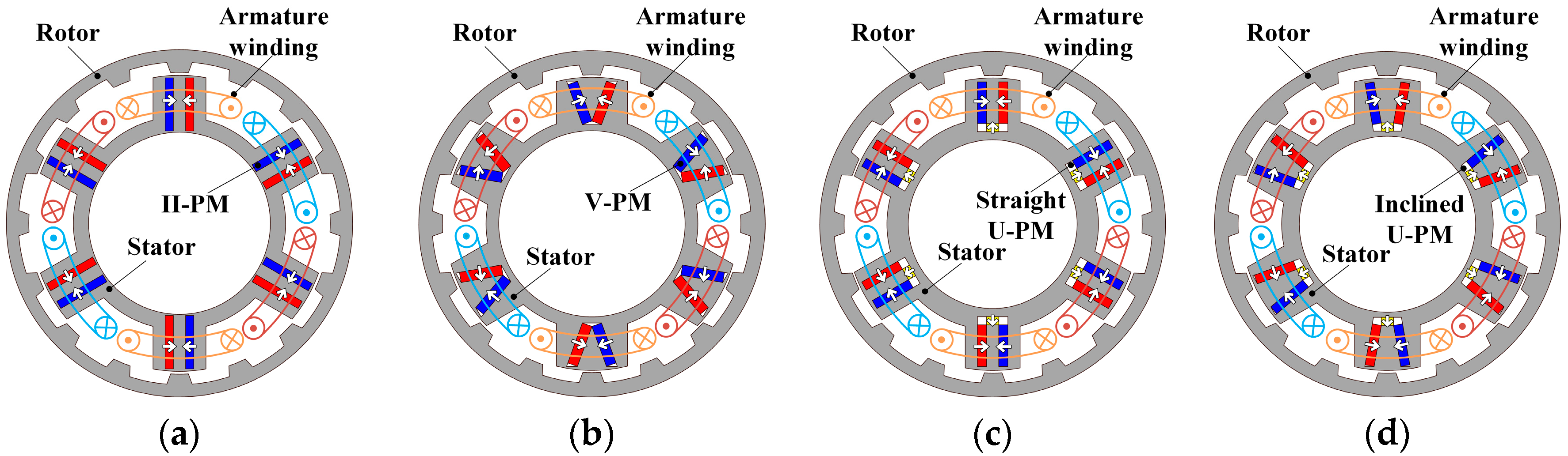
2.1. Machine Topologies

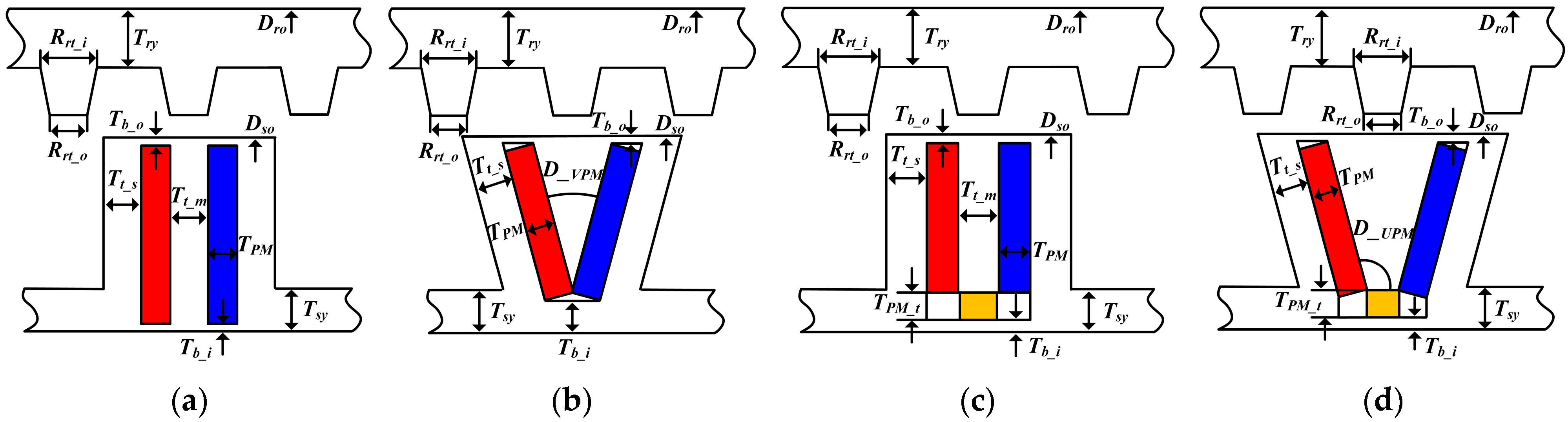
Figure 1 illustrates the topologies of the OR CP-FSPM machines, including the II-PM, V-PM, SU-PM, and IU-PM machines. A salient pole OR design is adopted in CP-FSPM machines, which is absent of windings and PMs. The armature winding coils and PM segments are placed on the stator. The following figures illustrate PM segments in blue, red, and yellow, with segments sharing the same magnetization direction being colored the same. The direction of magnetization is indicated by arrows. Additionally, different colors are used to represent the armature winding coils associated with different phases.
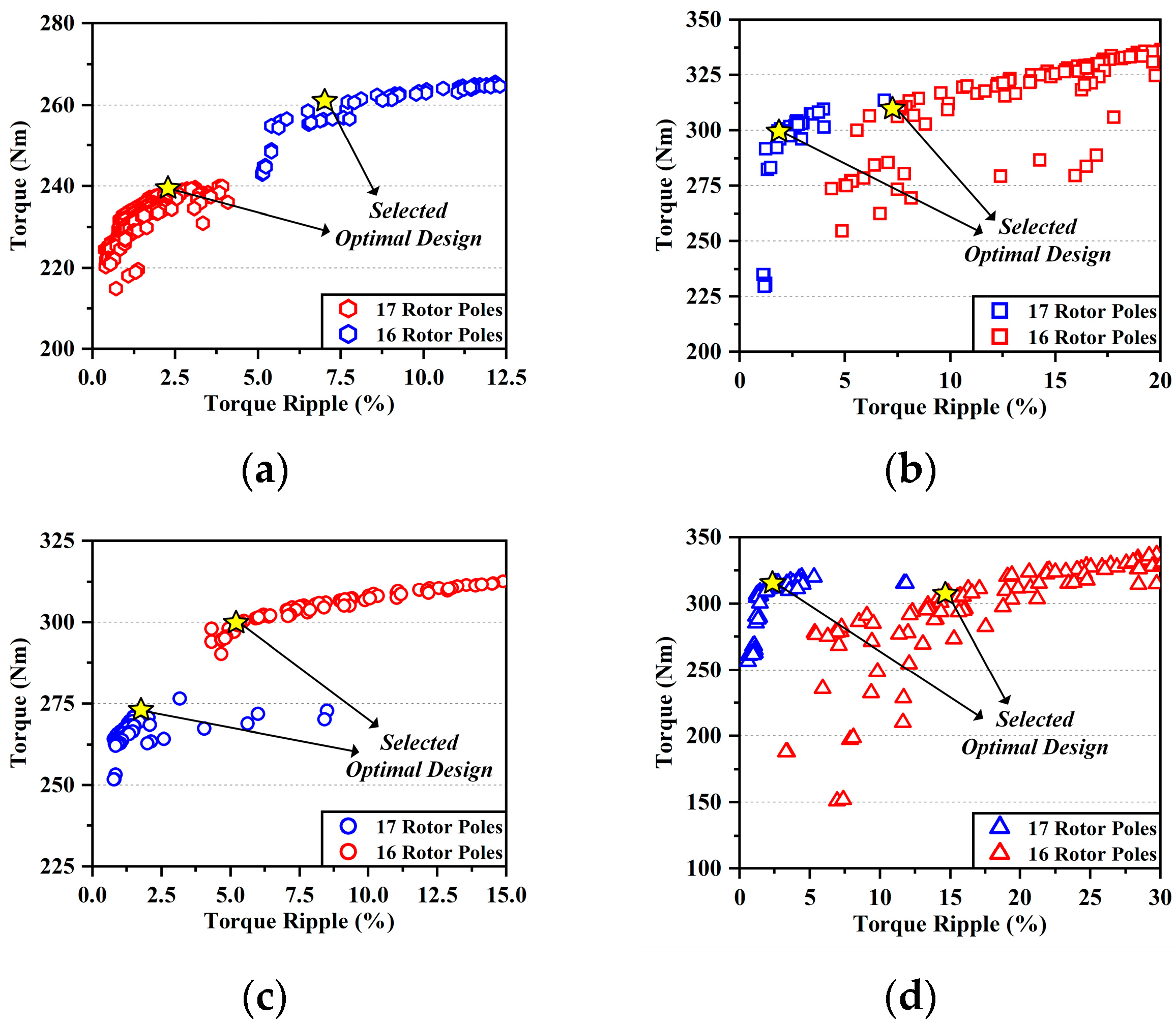
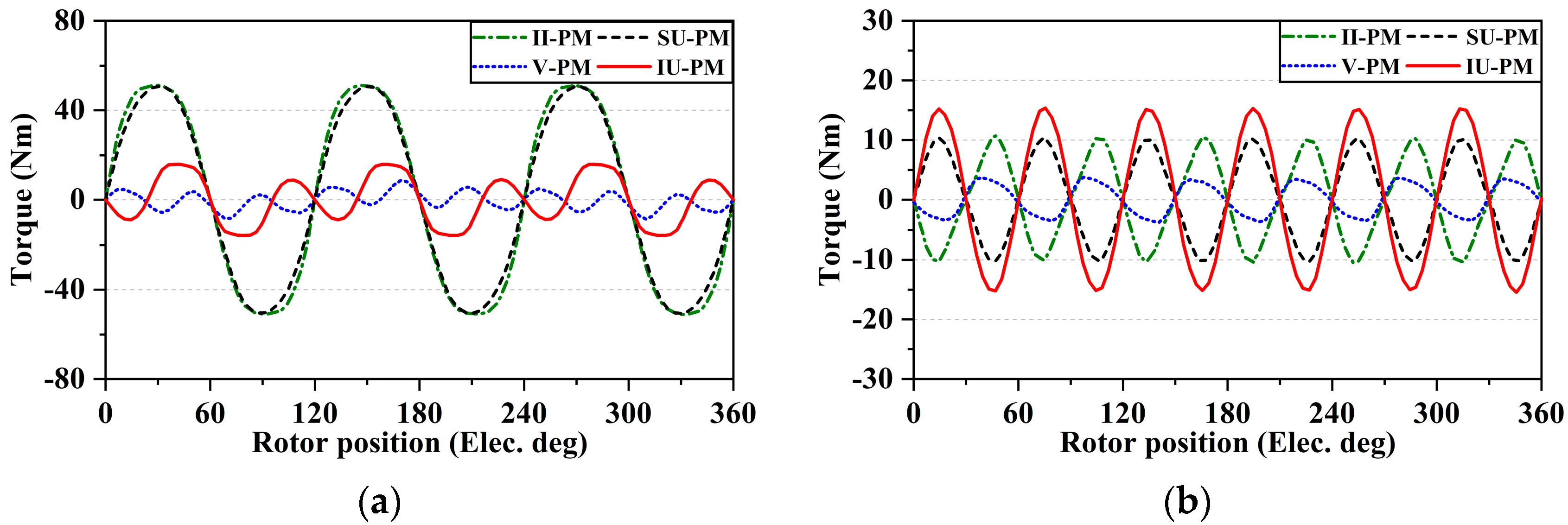
The CP-FSPM machines investigated in this study have six stator slots. In the meantime, machines with 16 (6/16) or 17 (6/17) rotor poles are notable due to the high open-circuit back EMFs and torque densities. On the one hand, concentrated winding (CW) with a high power factor can be applied in 6/16 machines to obtain short end-winding. However, the torque ripple is generally high in even-order rotor pole number machines. On the other hand, distributed winding (DW) is employed in 6/17 machines to achieve a low torque ripple while maintaining a high winding factor. In the following sections, both 6/16 and 6/17 machines are optimized and compared.
A flux-focusing PM array is located on each stator tooth of the CP-FSPM machines, and each array has the same polarity. As shown in Figure 1, the II-PM and V-PM array are formed of two PM segments, while the SU-PM and IU-PM machines are formed of three segments. The IU-PM machine is proposed by combining the features of the V-PM and SU-PM machines to improve the flux-focusing effect, as shown in Figure 1d. 
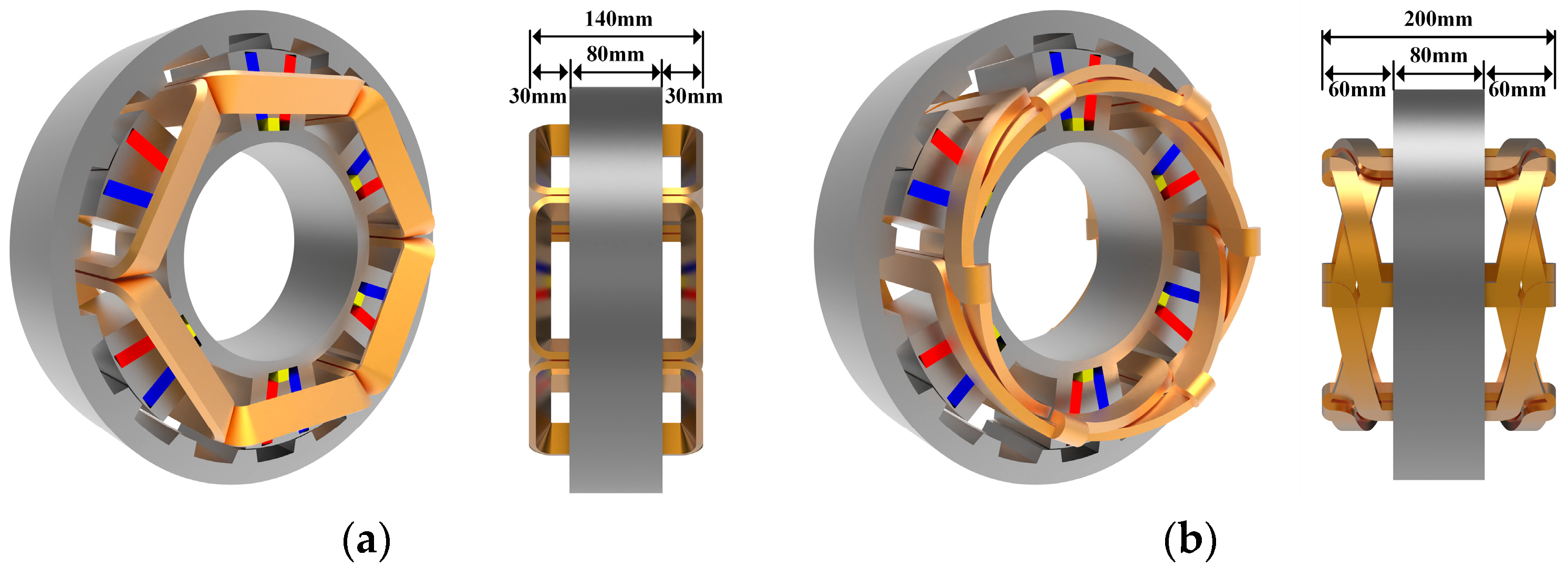
Table 1 provides the design parameters. The outer diameter and active stack length of CP-FSPM ma-chines are selected as 340 mm and 80 mm, respectively. The disk-like shape of the ma-chine is suitable for in-wheel applications.
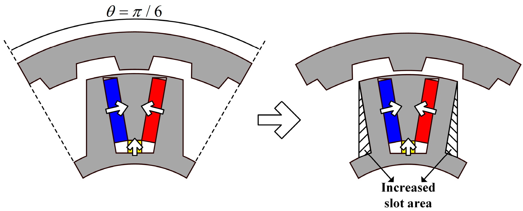
However, the parallel stator tooth design of the IU-PM machine leads to insufficient usage of the stator slot area. Therefore, an unparallel tooth design is adopted, inspired by [13]. As shown in 
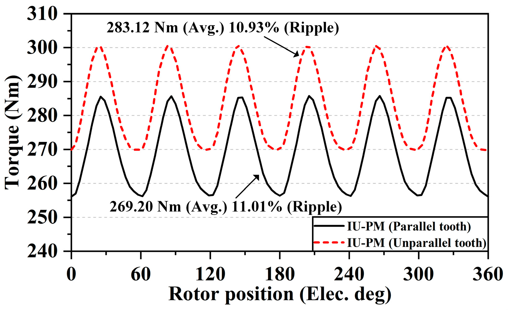
Figure 2, the edges of the stator tooth are inclined to the same angle as the PM segments in the modified design, which increases the slot area without influencing the flow of the magnetic flux circuit. By adopting the improved stator topology, the slot area of the inclined U-PM machine can increase by approximately 10%. In order to explicitly showcase the merit of the unparallel stator tooth design, 6/17 inclined U-PM machines with two types of stator topologies are optimized and compared with a current density of 4 A/mm2. As shown in 
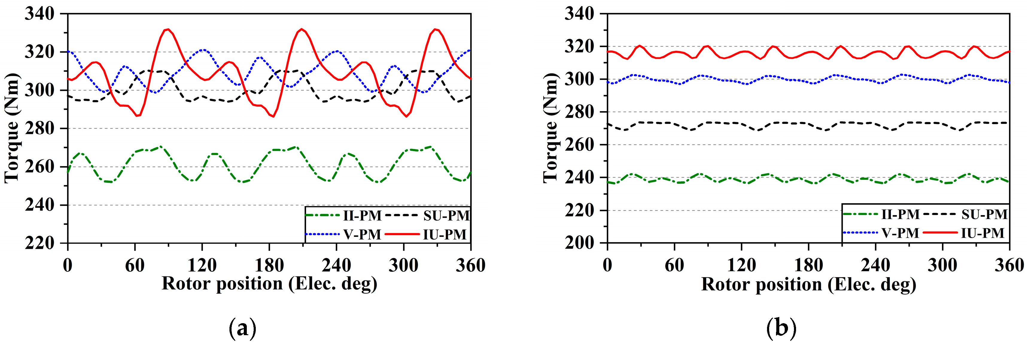
Figure 3, the average torque is improved by 5.17% after modifying the stator topology, although the torque ripple is increased as well. Furthermore, this unparallel stator tooth design is also employed in the V-PM machine.

2.2. Working Principle of CP-FSPM Machines

As one type of stator PM machine, the CP-FSPM machines operate based on the flux modulation effect. This section investigates the machine working principle using a semi-analytical model. The multiple working harmonics of air gap flux density are identified, and the contributions of various harmonics to the open-circuit back EMF are quantitatively analyzed.
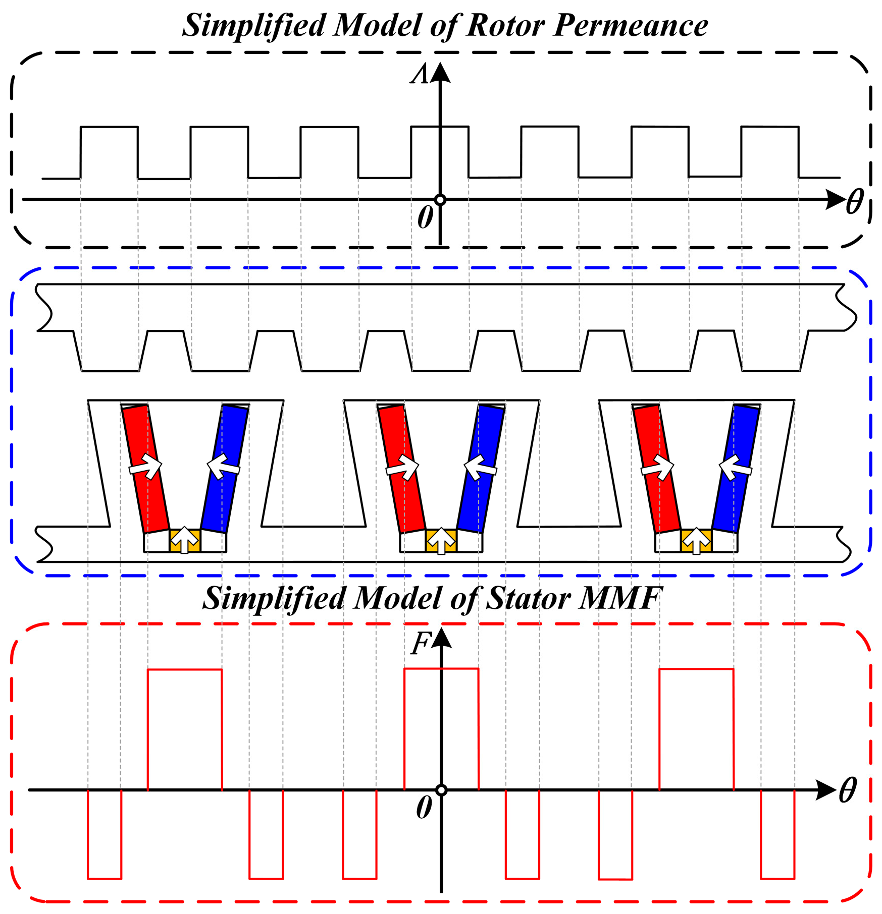
In an open-circuit condition, the simplified models of the rotor permeance model and the stator PM excited MMF are depicted in Figure 4. The distribution of rotor permeance exhibits an uneven distribution at the air gap side due to the salient pole structure, modulating the stator MMF to generate various harmonics of air gap flux density. The equivalent stator MMF, considering the PM excitation and the modulation effect of stator teeth, is a periodic function [15], which can be denoted by
F s ( θ ) = i = 1 , 3 , 5 F s i cos ( i P s θ ) ,
where Fsi is the i th-order MMF harmonic amplitude, and Ps is the fundamental PM MMF order, which is equal to the stator slot number in CP-FSPM machines.
As shown in Figure 4, the permeance model of the salient pole rotor is periodically distributed, which provides the essential flux modulation ability. The rotor permeance function is expressed as
Λ r ( θ , t ) = Λ 0 + j = 1 , 2 , 3 Λ j cos ( j N r ( θ ω r t ) ) ,
where L0 is the average permeance value, and Λj is the j th-order harmonic amplitude. In addition, Nr is the number of rotor poles, and ωr is the rotor angular speed.
Consequently, the air gap flux density can be derived from (1) and (2), which is shown as
B a ( θ , t )   =   F s ( θ ) Λ r ( θ , t ) = i = 1 , 3 , 5 F s i Λ 0 cos ( i P s θ ) + i = 1.3.5 j = 1 , 2 , 3 F s i Λ j 2 cos [ ( i P s ± j N r ) ( θ j N r i P s + j N r ω r t ) ] .
According to (3), the harmonic order of air gap flux density is related to both Ps and Nr. It is worthwhile to further investigate the harmonic components and the corresponding contributions to the generation of open-circuit back EMF.
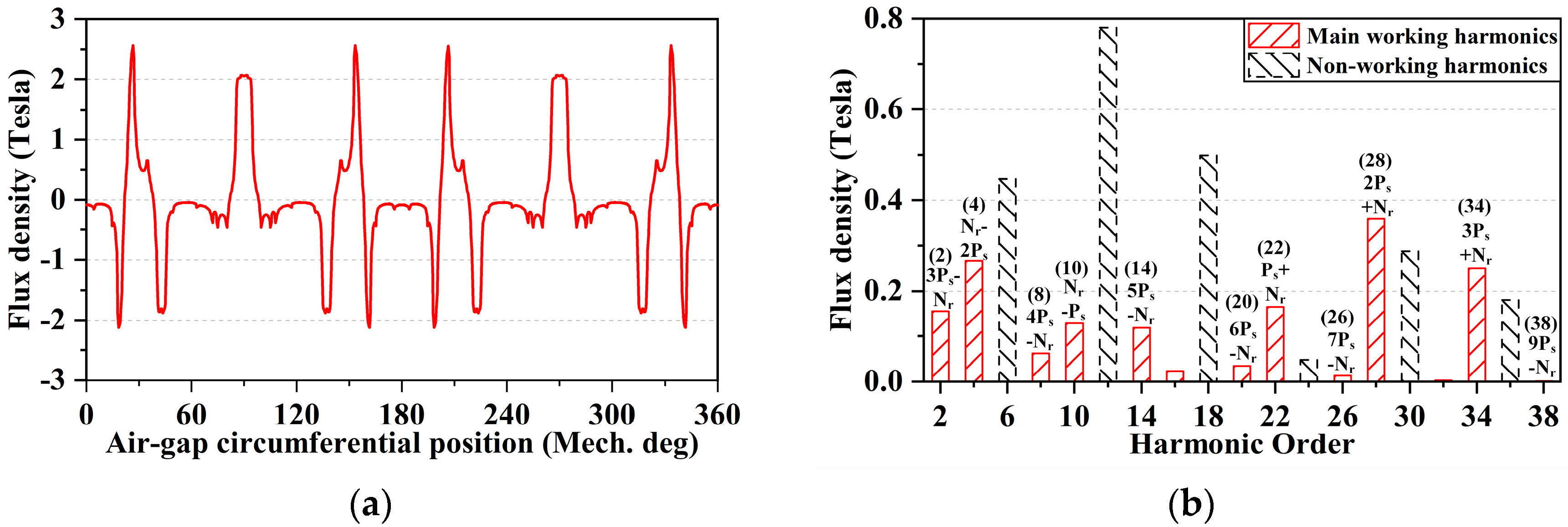
Figure 5a illustrates the finite element analysis (FEA) result of open-circuit air gap flux density considering the flux modulation effect, and the main working harmonics are identified, as shown in Figure 5b. The high amplitude of the 2nd- and 3rd-order of the 6 pole pairs fundamental harmonic causes the modulated 2, 4, 28, and 34 pole pairs harmonics to have relatively high amplitudes. In addition, the amplitudes of the 10 and 22 pole pairs harmonics are also high, which also significantly affects the back EMF. To quantitatively investigate the contribution of different working harmonics, the back EMF can be derived as
E p h ( t ) = d d t [ r g l s t 0 2 π B a ( θ , t ) N w ( θ ) d θ ] ,
where rg is the radius of the air gap, lst is the effective stack length, and Nw(θ) is the winding function, which can be expressed as
N w ( θ ) = v = 1 , 3 , 5 2 π v N c P a k w v cos ( v P a θ ) ,
where Nc is the number of conductors in series per phase, v is the harmonic order number, and kwv is the winding factor of the specific harmonic.
Combining (4) and (5), the open-circuit back EMF can be further denoted by
E p h ( t ) = 2 r g l s t N c sin ( N r ω r t ) n B a n k w n ω n ,
where n is the pole-pair number of the working harmonic, and Ban, kwn, and ωn are the harmonic amplitude of the air gap flux density, the winding factor of the harmonic, and the electrical angular speed of the harmonic, respectively.
It can be observed from (6) that the key parameters affecting the amplitude of back EMF are Ban, kwn, and ωn. Furthermore, the contributions of multiple working harmonics are quantitatively investigated, as listed in Table 2.
Due to a high pole ratio, harmonics with small pole pairs have higher electrical angular speeds. Therefore, the 2 and 4 pole pairs harmonics generate a considerable portion of the total back EMF. In contrast, because of the negative values of winding factors, the 8, 10, 20, 22, and 34 pole pairs harmonics produce negative back EMF. Considering the origination of working harmonics, the 2nd- and 3rd-order stator PM MMFs lead to the generation of 2, 4, and 28 pole pairs harmonics, which contribute the most to the back EMF. However, the 1st-order PM MMF is modulated to produce harmonics of 10 and 22 pole pairs, reducing the amplitude of back EMF. Thus, the enhancement of 2nd- and 3rd-order stator PM MMFs is essential to improving the performance of the machine. Moreover, the analytical result of the back EMF is close to the FEA results, with a slight error of 2.55%, validating the accuracy of the MMF-permeance model.

3. Design Considerations and Global Optimization

In order to pursue the optimal design of the CP-FSPM machines, global optimization is conducted using the NSGA-II. The general design parameters listed in Table 1 are kept the same in the CP-FSPM machines for a fair comparison. The structural design parameters of these machines are presented in Figure 6, and the key parameter range is shown in Table 3. The split ratio is defined as the ratio between the stator and rotor outer diameters. As shown in Figure 6b,d, the unparallel stator tooth design is applied in V-PM and IU-PM CP-FSPM machines to enlarge the effective area of the stator slot.
As mentioned in Section 2, both 6/16 and 6/17 machines are considered. Taking the proposed IU-PM machine as an example, the topologies of 6/16 and 6/17 machines, considering the armature winding configuration, are presented in Figure 7. Figure 7a shows the 6/16 inclined U-PM machine with CW, while the DW 6/17 machine with a coil pitch of 2 is illustrated in Figure 7b. Compared to the 6/16 machine, the end winding of the 6/17 machine is largely lengthened, and the total stack length is also enlarged, including the end winding height. On the one hand, the long end winding leads to an increased copper loss, which is a notable disadvantage of the 6/17 machine. On the other hand, the 6/17 machine has the merits of low cogging torque and torque ripple. Therefore, both 6/16 and 6/17 machines should be considered, and a constant copper loss is applied for the four types of CP-FSPM machines in order to conduct fair global optimization.
Due to a large number of design parameters, the generation number of optimization is selected as 100. In each generation, 80 individuals are simulated and ranked according to the dual objectives of maximizing the average torque and minimizing the torque ripple. In addition, the mutation and crossover factors are chosen as 0.1 and 0.9, respectively. The optimization results of 6/16 and 6/17 machines with different PM arrangements are depicted in Figure 8a–d. The optimal models of various CP-FSPM machines are selected on the Pareto front of the optimization results, which are marked by yellow stars as shown in Figure 8, and the optimized structural parameters of these machines are presented in Table 4.

4. Comparison of Electromagnetic Performance

The electromagnetic performance of the CP-FSPM machines is calculated and com-pared using FEA in this section.
The open-circuit phase back EMF of 6/16 and 6/17 CP-FSPM machines is simulated and compared, as shown in Figure 9a,b. Larger back EMF amplitudes can be observed in 6/17 machines due to the much higher pole ratios of the main working harmonics; in the 6/17 machines, the pole ratios of the main harmonics are 17 and 3.4, while the values in the 6/16 machines are 8 and 4. The high pole ratios can elevate the electrical angular speed of the working harmonics, which increases the back EMF. In addition, the back EMF waveforms of 6/17 machines have significantly lower THD values compared to 6/16 machines, leading to low torque ripple. In contrast, because of the severe flux leakage in the stator inner circumference, the II-PM machine shows the lowest back EMF. The cogging torque is depicted in Figure 10, and the peak-to-peak values of 6/16 machines are notably larger than 6/17 machines, except for the IU-PM machines. The II-PM and SU-PM machines exhibit larger cogging torque in 6/16 machines, while the IU-PM machine shows the largest cogging torque in 6/17 machines, except for the IU-PM machines. The II-PM and SU-PM machines exhibit larger cogging torque in 6/16 machines, while the IU-PM machine shows the largest cogging torque in 6/17 machines. In both conditions, the V-PM machines demonstrate the lowest cogging torque.
The torque characteristic is a crucial performance metric for electric machines. The steady torque under the same copper loss is investigated. The ampere-turn values of different CP-FS machines are shown in Table 5. As can be seen, the ampere-turn of 6/16 machines is higher than that of 6/17 machines, except for the V-PM machine, which is attributed to the lower resistances of CWs applied in 6/16 machines. Figure 11a,b present the output torque of 6/16 and 6/17 machines when the copper loss is set to a constant value of 600 W. The proposed IU-PM and V-PM machines show the highest average torque of 315 Nm and 309 Nm in 6/17 machines and 6/16 machines, respectively. Conversely, the output torque of the II-PM machine is the lowest. The 6/16 and 6/17 machines have their respective merits. On the one hand, due to the short end-winding in CW armature winding, the 6/16 machines exhibit a higher output torque than the 6/17 machines in most topologies, including the SU-PM machine, V-PM machine, and the II-PM machine, although the open-circuit back EMFs are notably lower. On the other hand, the 6/17 machines show low THD values of back EMF, and the cogging torque is significantly lower than in the 6/16 machines. Therefore, the torque ripple of the 6/17 machines at the rated condition is greatly lower than that of the 6/16 machines.
The loss and efficiency of CP-FSPM machines are summarized in Table 6. The 6/17 machines exhibit a larger iron loss than the 6/16 machines because of the increased working frequency. Consequently, the efficiencies of 6/16 machines are higher than those of 6/17 machines due to larger output torques and lower losses. In addition, the proposed IU-PM and V-PM machines exhibit the highest efficiencies in the 6/17 and 6/16 machines, respectively.

5. Conclusions

This study presents a comprehensive investigation and comparison of four OR CP-FSPM machines for in-wheel traction applications in EVs. The machines investigated comprise those with II-PM, V-PM, and SU-PM arrangements, as well as a proposed IU-PM arrangement that combines features of the V-PM and SU-PM arrangements to enhance the flux-focusing effect. A semi-analytical MMF-permeance model is established to explain the working principle. The model analyzes the main working harmonics of air gap flux density and the harmonic contributions to the open-circuit back EMF. Furthermore, globally optimized 6/16 and 6/17 CP-FSPM machines are compared. The 6/16 machines generally exhibit higher torque densities and efficiencies, while the 6/17 machines show a more stable output torque with torque ripples generally lower than 3%. Among these machines, the proposed 6/17 IU-PM machine demonstrates the best performance in terms of output torque, showing a 31.8% higher average torque compared to the 6/17 II-PM machine. In addition, the 6/16 V-PM machine exhibits the highest efficiency of 93.3% among the OR CP-FSPM machines. The performances of these machines will be further investigated and compared in future works. The performance under different speeds and loadings will be investigated to provide a comprehensive comparison of the proposed machines, especially focusing on the efficiency maps and flux-weakening abilities. Additionally, multi-physics simulations will be conducted, including the mechanical strength of machine components, heat distribution, and vibration under different working conditions.

Author Contributions

Conceptualization, Y.B., W.F. and S.N.; methodology, Y.B., W.F. and J.H.; validation, Y.B. and J.H.; optimization, Y.B. and J.H.; writing—original draft preparation, Y.B.; writing—review and editing, Y.B., W.F. and S.N.; visualization, Y.B. and J.H.; supervision, W.F. and S.N.; funding acquisition, W.F. and S.N. All authors have read and agreed to the published version of the manuscript.

Funding

This work was funded by the Research Grant Council of the Hong Kong Government under Project PolyU 152109/20E, and in part by the State Key Laboratory of Reliability and Intelligence of Electrical Equipment, Hebei University of Technology, under Grant No. EE-RI_KF2021003.

Data Availability Statement

Not applicable.

Conflicts of Interest

The authors declare no conflict of interest.

References

  1. Chau, K.T.; Chan, C.C.; Liu, C. Overview of Permanent-Magnet Brushless Drives for Electric and Hybrid Electric Vehicles. IEEE Trans. Ind. Electron. 2008, 55, 2246–2257. [Google Scholar] [CrossRef]
  2. Cai, S.; Kirtley, J.L.; Lee, C.H.T. Critical Review of Direct-Drive Electrical Machine Systems for Electric and Hybrid Electric Vehicles. IEEE Trans. Energy Convers. 2022, 37, 2657–2668. [Google Scholar] [CrossRef]
  3. Wang, X.; Gao, P.; Wang, G. The design of Halbach array permanent magnet for In-wheel motor. In Proceedings of the 2013 International Conference on Electrical Machines and Systems (ICEMS), Busan, Republic of Korea, 26–29 October 2013; IEEE: New York, NY, USA, 2013; pp. 1252–1255. [Google Scholar]
  4. Fu, W.N.; Ho, S.L. A Quantitative Comparative Analysis of a Novel Flux-Modulated Permanent-Magnet Motor for Low-Speed Drive. IEEE Trans. Magn. 2010, 46, 127–134. [Google Scholar] [CrossRef]
  5. Liu, C. Design of a new outer-rotor flux-controllable vernier PM in-wheel motor drive for electric vehicle. In Proceedings of the 2011 International Conference on Electrical Machines and Systems (ICEMS), Beijing, China, 20–23 August 2011; IEEE: New York, NY, USA, 2011; pp. 1–6. [Google Scholar]
  6. Cheng, M.; Han, P.; Hua, W. General Airgap Field Modulation Theory for Electrical Machines. IEEE Trans. Ind. Electron. 2017, 64, 6063–6074. [Google Scholar] [CrossRef]
  7. Chen, H.; EL-Refaie, A.M.; Demerdash, N.A.O. Flux-Switching Permanent Magnet Machines: A Review of Opportunities and Challenges—Part I: Fundamentals and Topologies. IEEE Trans. Energy Convers. 2020, 35, 684–698. [Google Scholar] [CrossRef]
  8. Bi, Y.; Fu, W.; Niu, S.; Zhao, X.; Huang, J.; Qiao, Z. Torque Enhancement of a Dual-PM Flux-Switching Machine with Improved Multiple High-Order Working Harmonics. IEEE Trans. Transp. Electrific. 2023. [Google Scholar] [CrossRef]
  9. Hua, W.; Zhang, H.; Cheng, M.; Meng, J.; Hou, C. An outer-rotor flux-switching permanent-magnet-machine with wedge-shaped magnets for in-wheel light traction. IEEE Trans. Ind. Electron. 2017, 64, 69–80. [Google Scholar] [CrossRef]
  10. Fei, W.Z.; Shen, J.X. Novel Permanent Magnet Switching Flux Motors. In Proceedings of the 41st International Universities Power Engineering Conference, Newcastle upon Tyne, UK, 6–8 September 2006; IEEE: New York, NY, USA, 2006; pp. 729–733. [Google Scholar]
  11. Zhou, Y.J.; Zhu, Z.Q. Torque Density and Magnet Usage Efficiency Enhancement of Sandwiched Switched Flux Permanent Magnet Machines Using V-Shaped Magnets. IEEE Trans. Magn. 2013, 49, 3834–3837. [Google Scholar] [CrossRef]
  12. Zhu, X.; Shu, Z.; Quan, L.; Xiang, Z.; Pan, X. Multi-Objective Optimization of an Outer-Rotor V-Shaped Permanent Magnet Flux Switching Motor Based on Multi-Level Design Method. IEEE Trans. Magn. 2016, 52, 1–8. [Google Scholar] [CrossRef]
  13. Yang, H.; Li, Y.; Lin, H.; Zhu, Z.Q.; Lyu, S. Principle Investigation and Performance Comparison of Consequent-Pole Switched Flux PM Machines. IEEE Trans. Transp. Electrific. 2021, 7, 766–778. [Google Scholar] [CrossRef]
  14. Zhao, G.; Hua, W. Comparative Study Between a Novel Multi-Tooth and a V-Shaped Flux-Switching Permanent Magnet Machines. IEEE Trans. Magn. 2019, 55, 1–8. [Google Scholar] [CrossRef]
  15. Chen, C.; Ren, X.; Li, D.; Qu, R.; Liu, K.; Zou, T. Torque performance enhancement of flux-switching permanent magnet machines with dual sets of magnet arrangements. IEEE Trans. Transp. Electrific. 2021, 7, 2623–2634. [Google Scholar] [CrossRef]
Figure 1. Topologies of OR CP-FSPM machines: (a) II-PM machine; (b) V-PM machine; (c) SU-PM machine; (d) proposed IU-PM machine.
Energies 16 06650 g001
Figure 2. Comparison of parallel and unparallel stator tooth design in the proposed IU-PM machine.
Energies 16 06650 g002
Figure 3. Torque of the proposed IU-PM machine with parallel and unparallel stator tooth design.
Energies 16 06650 g003
Figure 4. Simplified MMF-permeance model of the proposed inclined U-PM CP-FSPM machine.
Energies 16 06650 g004
Figure 5. Air gap flux density of the IU-PM machine: (a) distribution; (b) FFT spectrum.
Energies 16 06650 g005
Figure 6. Illustration of structural parameters: (a) II-PM machine; (b) V-PM machine; (c) SU-PM machine; (d) IU-PM machine.
Energies 16 06650 g006
Figure 7. Configurations of the proposed inclined U-PM machine with the armature winding: (a) 6/16 CW machine; (b) 6/17 DW machine.
Energies 16 06650 g007
Figure 8. Optimization results of 6/16 and 6/17 CP-FSPM machines: (a) II-PM machine; (b) V-PM machine; (c) SU-PM machine; (d) IU-PM machine.
Energies 16 06650 g008
Figure 9. Comparison of open-circuit back EMF: (a) 6/16 machines; (b) 6/17 machines.
Energies 16 06650 g009
Figure 10. Comparison of cogging torques: (a) 6/16 machines; (b) 6/17 machines.
Energies 16 06650 g010
Figure 11. Comparison of torque performance: (a) 6/16 machines; (b) 6/17 machines.
Energies 16 06650 g011
Table 1. General design parameters.
ParametersUnitValues
Rotor outer diametermm340
Active stack lengthmm80
Air gap lengthmm0.8
Rated rotation speedr/min300
Conductor turns per coil-75
Stator slot number-6
Filling factor-0.5
PM volumeL0.48
PM material-N38UH
Steel material-DW310_35
Table 2. Composition of the open-circuit phase back EMF at 300 r/min.
Pole-PairkwvwvBa (T)Eph (V)
3PsNr, 20.86616ωm/20.155113.49
Nr − 2Ps, 40.86616ωm/40.26797.71
4PsNr, 8−0.86616ωm/80.063−11.50
NrPs, 10−0.86616ωm/100.129−18.90
5PsNr, 140.86616ωm/140.11912.40
6PsNr, 20−0.86616ωm/200.035−2.55
Ps + Nr, 22−0.86616ωm/220.165−10.94
7PsNr, 260.86616ωm/260.0130.74
2Ps + Nr, 280.86616ωm/280.35918.77
3Ps + Nr, 34−0.86616ωm/340.250−10.73
9PsNr, 380.86616ωm/380.0010.05
Total phase back EMF—analytical (V)188.54
Total phase back EMF—FEA (V)193.34
Table 3. Variation ranges of design parameters in optimization.
ParametersUnitRange
Split ratio, Dso/Dromm0.7~0.9
Outer magnetic bridge thickness, Tb_omm2~6
Inner magnetic bridge thickness, Tb_imm1~20
Side tooth thickness, Tt_smm6~15
Middle tooth thickness, Tt_mmm6~15
Main PM thickness, TPMmm6~12
Top PM thickness, TPM_tmm6~12
VPM inclined angle, D_VPMdeg.0~50
UPM inclined angle, D_UPMdeg.90~110
Rotor yoke thickness, Trymm10~30
Rotor tooth outer width ratio, Rrt_o-0.2~0.7
Rotor tooth inner width ratio, Rrt_i-0.2~0.9
Table 4. Optimized structural parameters of CP-FSPM machines.
ParametersUnitII-PM MachineV-PM MachineSU-PM MachineIU-PM Machine
6/166/176/166/176/166/176/166/17
Split ratio, Dso/Dromm0.820.790.820.810.820.790.810.8
Outer magnetic bridge thickness, Tb_omm222.042.0222.392.112.01
Inner magnetic bridge thickness, Tb_imm111.839.0319.919.61014.3
Side tooth thickness, Tt_smm11.41514.9114.7412.311.112.812.8
Middle tooth thickness, Tt_mmm1515--1514.912.913.7
Main PM thickness, TPMmm7.639.5911.597.87.7111.177.549.73
Top PM thickness, TPM_tmm----6.396.027.49.86
VPM inclined angle, D_VPMdeg.--35.924.8----
UPM inclined angle, D_UPMdeg.------100.396.8
Rotor yoke thickness, Trymm16.419.515.8117.8516.720.918.322.6
Rotor tooth outer width ratio, Rrt_o-0.340.280.220.390.320.230.40.38
Rotor tooth inner width ratio, Rrt_i-0.460.410.590.570.50.470.650.42
Table 5. Operation parameters of CP-FSPM machines.
ParametersII-PM MachineV-PM MachineSU-PM MachineIU-PM Machine
6/166/176/166/176/166/176/166/17
Copper loss600 W
Ampere-turn3405 A∙t2255 A∙t2619 A∙t2836 A∙t3843 A∙t2592 A∙t3324 A∙t2458 A∙t
Rated rotation speed300 r/min
Cooling methodNatural cooling
Table 6. Comparison of open-circuit and on-load performance.
IU-PMSU-PMV-PMII-PM
6/166/176/166/176/166/176/166/17
Ephase (V)175313162282167298134154
Tavg (Nm)308315300272309299261239
Tripple (%)14.822.565.471.87.251.887.092.42
Tcog (Nm)31.7330.83101.5320.8517.407.59102.1021.47
Pcopper (W)600
Piron (W)172224174.1206.595.7188.9123.5126.6
η (%)92.692.392.491.493.392.291.991.2
Disclaimer/Publisher’s Note: The statements, opinions and data contained in all publications are solely those of the individual author(s) and contributor(s) and not of MDPI and/or the editor(s). MDPI and/or the editor(s) disclaim responsibility for any injury to people or property resulting from any ideas, methods, instructions or products referred to in the content.

