Comparative Analysis of Consequent-Pole Flux-Switching Machines with Different Permanent Magnet Arrangements for Outer-Rotor In-Wheel Direct-Drive Applications
Abstract
:1. Introduction
2. Topologies and the Working Principle of OR CP-FSPM Machines
2.1. Machine Topologies
2.2. Working Principle of CP-FSPM Machines
3. Design Considerations and Global Optimization
4. Comparison of Electromagnetic Performance
5. Conclusions
Author Contributions
Funding
Data Availability Statement
Conflicts of Interest
References
- Chau, K.T.; Chan, C.C.; Liu, C. Overview of Permanent-Magnet Brushless Drives for Electric and Hybrid Electric Vehicles. IEEE Trans. Ind. Electron. 2008, 55, 2246–2257. [Google Scholar] [CrossRef]
- Cai, S.; Kirtley, J.L.; Lee, C.H.T. Critical Review of Direct-Drive Electrical Machine Systems for Electric and Hybrid Electric Vehicles. IEEE Trans. Energy Convers. 2022, 37, 2657–2668. [Google Scholar] [CrossRef]
- Wang, X.; Gao, P.; Wang, G. The design of Halbach array permanent magnet for In-wheel motor. In Proceedings of the 2013 International Conference on Electrical Machines and Systems (ICEMS), Busan, Republic of Korea, 26–29 October 2013; IEEE: New York, NY, USA, 2013; pp. 1252–1255. [Google Scholar]
- Fu, W.N.; Ho, S.L. A Quantitative Comparative Analysis of a Novel Flux-Modulated Permanent-Magnet Motor for Low-Speed Drive. IEEE Trans. Magn. 2010, 46, 127–134. [Google Scholar] [CrossRef]
- Liu, C. Design of a new outer-rotor flux-controllable vernier PM in-wheel motor drive for electric vehicle. In Proceedings of the 2011 International Conference on Electrical Machines and Systems (ICEMS), Beijing, China, 20–23 August 2011; IEEE: New York, NY, USA, 2011; pp. 1–6. [Google Scholar]
- Cheng, M.; Han, P.; Hua, W. General Airgap Field Modulation Theory for Electrical Machines. IEEE Trans. Ind. Electron. 2017, 64, 6063–6074. [Google Scholar] [CrossRef]
- Chen, H.; EL-Refaie, A.M.; Demerdash, N.A.O. Flux-Switching Permanent Magnet Machines: A Review of Opportunities and Challenges—Part I: Fundamentals and Topologies. IEEE Trans. Energy Convers. 2020, 35, 684–698. [Google Scholar] [CrossRef]
- Bi, Y.; Fu, W.; Niu, S.; Zhao, X.; Huang, J.; Qiao, Z. Torque Enhancement of a Dual-PM Flux-Switching Machine with Improved Multiple High-Order Working Harmonics. IEEE Trans. Transp. Electrific. 2023. [Google Scholar] [CrossRef]
- Hua, W.; Zhang, H.; Cheng, M.; Meng, J.; Hou, C. An outer-rotor flux-switching permanent-magnet-machine with wedge-shaped magnets for in-wheel light traction. IEEE Trans. Ind. Electron. 2017, 64, 69–80. [Google Scholar] [CrossRef]
- Fei, W.Z.; Shen, J.X. Novel Permanent Magnet Switching Flux Motors. In Proceedings of the 41st International Universities Power Engineering Conference, Newcastle upon Tyne, UK, 6–8 September 2006; IEEE: New York, NY, USA, 2006; pp. 729–733. [Google Scholar]
- Zhou, Y.J.; Zhu, Z.Q. Torque Density and Magnet Usage Efficiency Enhancement of Sandwiched Switched Flux Permanent Magnet Machines Using V-Shaped Magnets. IEEE Trans. Magn. 2013, 49, 3834–3837. [Google Scholar] [CrossRef]
- Zhu, X.; Shu, Z.; Quan, L.; Xiang, Z.; Pan, X. Multi-Objective Optimization of an Outer-Rotor V-Shaped Permanent Magnet Flux Switching Motor Based on Multi-Level Design Method. IEEE Trans. Magn. 2016, 52, 1–8. [Google Scholar] [CrossRef]
- Yang, H.; Li, Y.; Lin, H.; Zhu, Z.Q.; Lyu, S. Principle Investigation and Performance Comparison of Consequent-Pole Switched Flux PM Machines. IEEE Trans. Transp. Electrific. 2021, 7, 766–778. [Google Scholar] [CrossRef]
- Zhao, G.; Hua, W. Comparative Study Between a Novel Multi-Tooth and a V-Shaped Flux-Switching Permanent Magnet Machines. IEEE Trans. Magn. 2019, 55, 1–8. [Google Scholar] [CrossRef]
- Chen, C.; Ren, X.; Li, D.; Qu, R.; Liu, K.; Zou, T. Torque performance enhancement of flux-switching permanent magnet machines with dual sets of magnet arrangements. IEEE Trans. Transp. Electrific. 2021, 7, 2623–2634. [Google Scholar] [CrossRef]


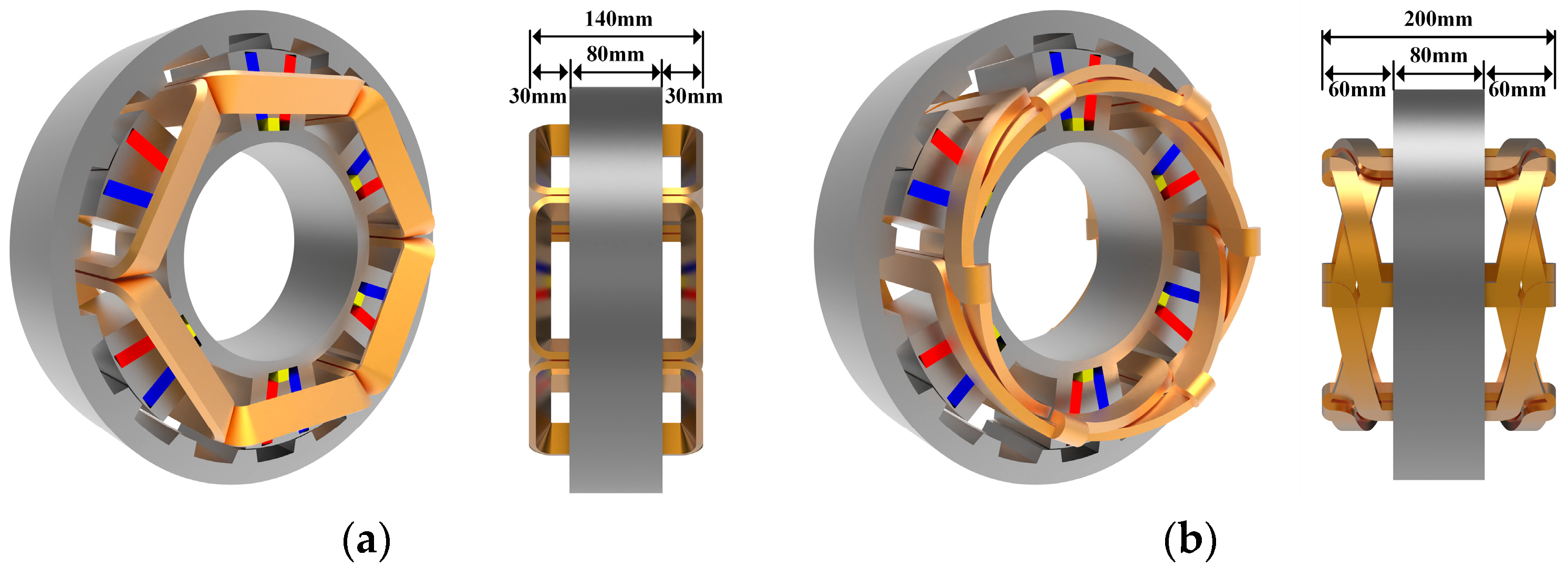
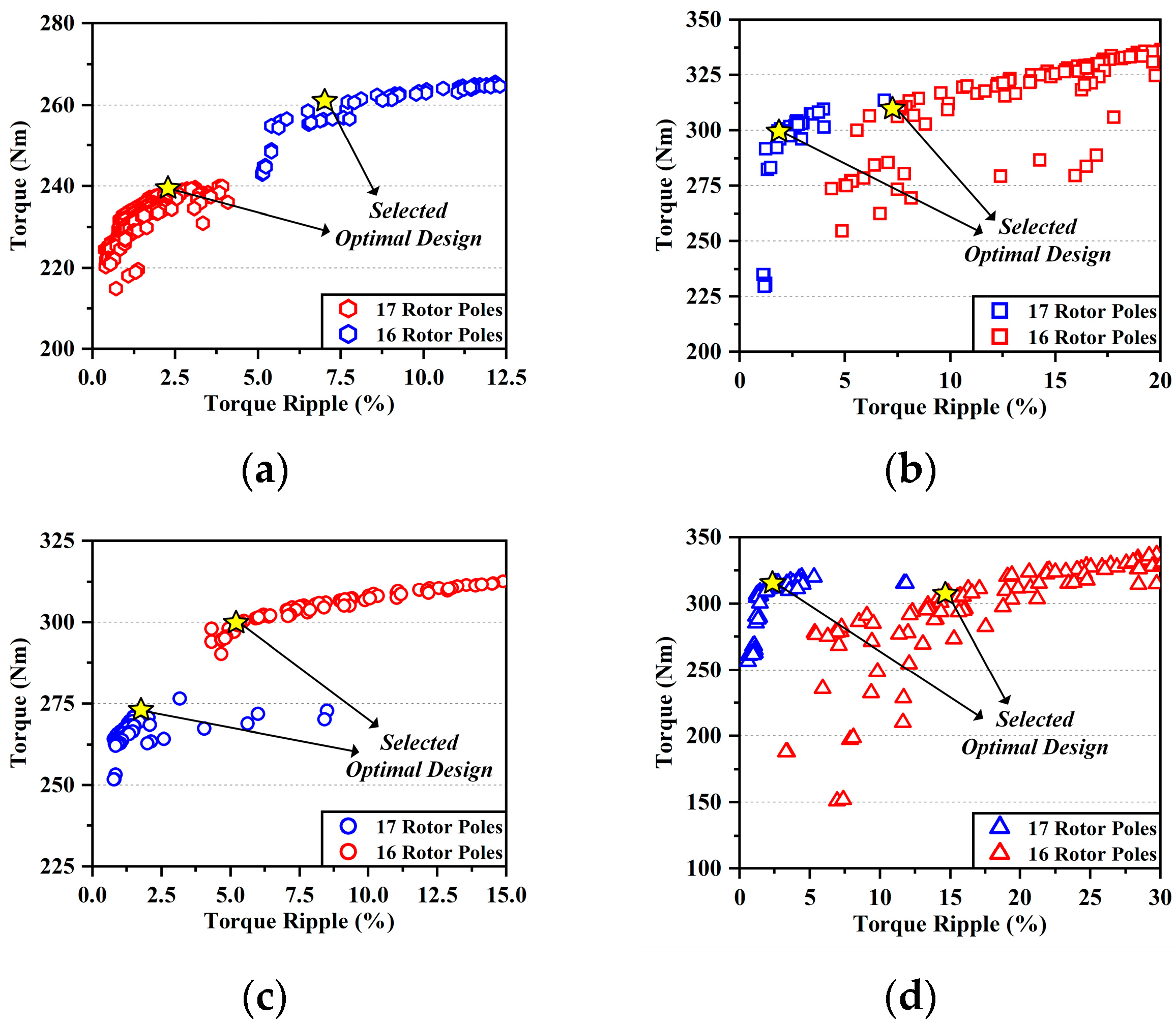

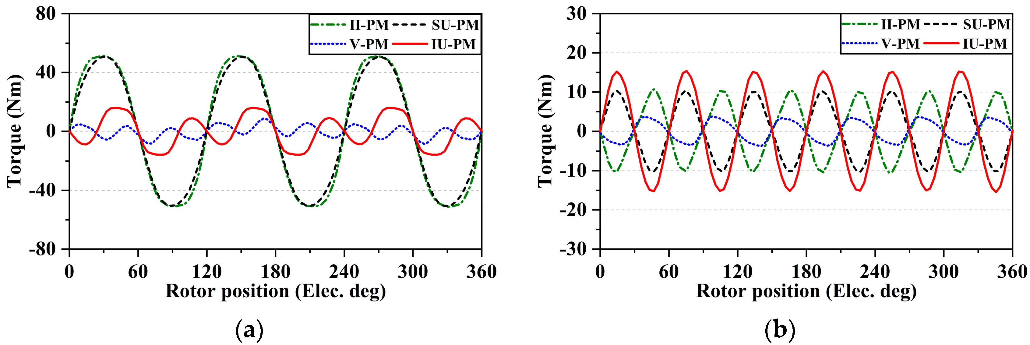
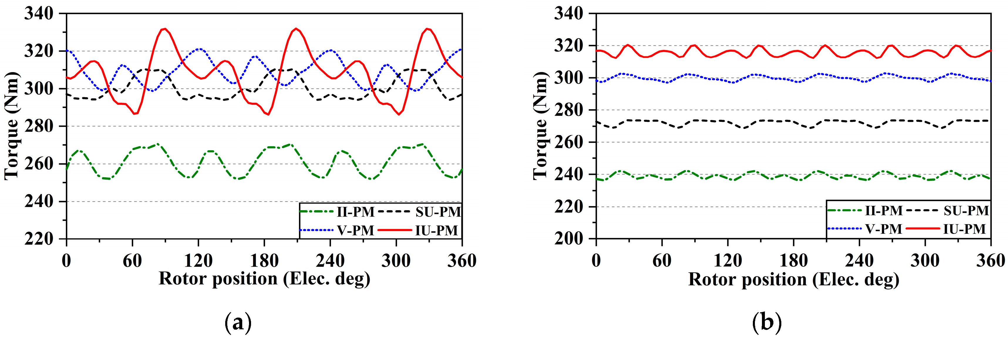
| Parameters | Unit | Values |
|---|---|---|
| Rotor outer diameter | mm | 340 |
| Active stack length | mm | 80 |
| Air gap length | mm | 0.8 |
| Rated rotation speed | r/min | 300 |
| Conductor turns per coil | - | 75 |
| Stator slot number | - | 6 |
| Filling factor | - | 0.5 |
| PM volume | L | 0.48 |
| PM material | - | N38UH |
| Steel material | - | DW310_35 |
| Pole-Pair | kwv | wv | Ba (T) | Eph (V) |
|---|---|---|---|---|
| 3Ps − Nr, 2 | 0.866 | 16ωm/2 | 0.155 | 113.49 |
| Nr − 2Ps, 4 | 0.866 | 16ωm/4 | 0.267 | 97.71 |
| 4Ps − Nr, 8 | −0.866 | 16ωm/8 | 0.063 | −11.50 |
| Nr − Ps, 10 | −0.866 | 16ωm/10 | 0.129 | −18.90 |
| 5Ps − Nr, 14 | 0.866 | 16ωm/14 | 0.119 | 12.40 |
| 6Ps − Nr, 20 | −0.866 | 16ωm/20 | 0.035 | −2.55 |
| Ps + Nr, 22 | −0.866 | 16ωm/22 | 0.165 | −10.94 |
| 7Ps − Nr, 26 | 0.866 | 16ωm/26 | 0.013 | 0.74 |
| 2Ps + Nr, 28 | 0.866 | 16ωm/28 | 0.359 | 18.77 |
| 3Ps + Nr, 34 | −0.866 | 16ωm/34 | 0.250 | −10.73 |
| 9Ps − Nr, 38 | 0.866 | 16ωm/38 | 0.001 | 0.05 |
| Total phase back EMF—analytical (V) | 188.54 | |||
| Total phase back EMF—FEA (V) | 193.34 | |||
| Parameters | Unit | Range |
|---|---|---|
| Split ratio, Dso/Dro | mm | 0.7~0.9 |
| Outer magnetic bridge thickness, Tb_o | mm | 2~6 |
| Inner magnetic bridge thickness, Tb_i | mm | 1~20 |
| Side tooth thickness, Tt_s | mm | 6~15 |
| Middle tooth thickness, Tt_m | mm | 6~15 |
| Main PM thickness, TPM | mm | 6~12 |
| Top PM thickness, TPM_t | mm | 6~12 |
| VPM inclined angle, D_VPM | deg. | 0~50 |
| UPM inclined angle, D_UPM | deg. | 90~110 |
| Rotor yoke thickness, Try | mm | 10~30 |
| Rotor tooth outer width ratio, Rrt_o | - | 0.2~0.7 |
| Rotor tooth inner width ratio, Rrt_i | - | 0.2~0.9 |
| Parameters | Unit | II-PM Machine | V-PM Machine | SU-PM Machine | IU-PM Machine | ||||
|---|---|---|---|---|---|---|---|---|---|
| 6/16 | 6/17 | 6/16 | 6/17 | 6/16 | 6/17 | 6/16 | 6/17 | ||
| Split ratio, Dso/Dro | mm | 0.82 | 0.79 | 0.82 | 0.81 | 0.82 | 0.79 | 0.81 | 0.8 |
| Outer magnetic bridge thickness, Tb_o | mm | 2 | 2 | 2.04 | 2.02 | 2 | 2.39 | 2.11 | 2.01 |
| Inner magnetic bridge thickness, Tb_i | mm | 1 | 1 | 1.83 | 9.03 | 19.9 | 19.6 | 10 | 14.3 |
| Side tooth thickness, Tt_s | mm | 11.4 | 15 | 14.91 | 14.74 | 12.3 | 11.1 | 12.8 | 12.8 |
| Middle tooth thickness, Tt_m | mm | 15 | 15 | - | - | 15 | 14.9 | 12.9 | 13.7 |
| Main PM thickness, TPM | mm | 7.63 | 9.59 | 11.59 | 7.8 | 7.71 | 11.17 | 7.54 | 9.73 |
| Top PM thickness, TPM_t | mm | - | - | - | - | 6.39 | 6.02 | 7.4 | 9.86 |
| VPM inclined angle, D_VPM | deg. | - | - | 35.9 | 24.8 | - | - | - | - |
| UPM inclined angle, D_UPM | deg. | - | - | - | - | - | - | 100.3 | 96.8 |
| Rotor yoke thickness, Try | mm | 16.4 | 19.5 | 15.81 | 17.85 | 16.7 | 20.9 | 18.3 | 22.6 |
| Rotor tooth outer width ratio, Rrt_o | - | 0.34 | 0.28 | 0.22 | 0.39 | 0.32 | 0.23 | 0.4 | 0.38 |
| Rotor tooth inner width ratio, Rrt_i | - | 0.46 | 0.41 | 0.59 | 0.57 | 0.5 | 0.47 | 0.65 | 0.42 |
| Parameters | II-PM Machine | V-PM Machine | SU-PM Machine | IU-PM Machine | ||||
|---|---|---|---|---|---|---|---|---|
| 6/16 | 6/17 | 6/16 | 6/17 | 6/16 | 6/17 | 6/16 | 6/17 | |
| Copper loss | 600 W | |||||||
| Ampere-turn | 3405 A∙t | 2255 A∙t | 2619 A∙t | 2836 A∙t | 3843 A∙t | 2592 A∙t | 3324 A∙t | 2458 A∙t |
| Rated rotation speed | 300 r/min | |||||||
| Cooling method | Natural cooling | |||||||
| IU-PM | SU-PM | V-PM | II-PM | |||||
|---|---|---|---|---|---|---|---|---|
| 6/16 | 6/17 | 6/16 | 6/17 | 6/16 | 6/17 | 6/16 | 6/17 | |
| Ephase (V) | 175 | 313 | 162 | 282 | 167 | 298 | 134 | 154 |
| Tavg (Nm) | 308 | 315 | 300 | 272 | 309 | 299 | 261 | 239 |
| Tripple (%) | 14.82 | 2.56 | 5.47 | 1.8 | 7.25 | 1.88 | 7.09 | 2.42 |
| Tcog (Nm) | 31.73 | 30.83 | 101.53 | 20.85 | 17.40 | 7.59 | 102.10 | 21.47 |
| Pcopper (W) | 600 | |||||||
| Piron (W) | 172 | 224 | 174.1 | 206.5 | 95.7 | 188.9 | 123.5 | 126.6 |
| η (%) | 92.6 | 92.3 | 92.4 | 91.4 | 93.3 | 92.2 | 91.9 | 91.2 |
Disclaimer/Publisher’s Note: The statements, opinions and data contained in all publications are solely those of the individual author(s) and contributor(s) and not of MDPI and/or the editor(s). MDPI and/or the editor(s) disclaim responsibility for any injury to people or property resulting from any ideas, methods, instructions or products referred to in the content. |
© 2023 by the authors. Licensee MDPI, Basel, Switzerland. This article is an open access article distributed under the terms and conditions of the Creative Commons Attribution (CC BY) license (https://creativecommons.org/licenses/by/4.0/).
Share and Cite
Bi, Y.; Fu, W.; Niu, S.; Huang, J. Comparative Analysis of Consequent-Pole Flux-Switching Machines with Different Permanent Magnet Arrangements for Outer-Rotor In-Wheel Direct-Drive Applications. Energies 2023, 16, 6650. https://doi.org/10.3390/en16186650
Bi Y, Fu W, Niu S, Huang J. Comparative Analysis of Consequent-Pole Flux-Switching Machines with Different Permanent Magnet Arrangements for Outer-Rotor In-Wheel Direct-Drive Applications. Energies. 2023; 16(18):6650. https://doi.org/10.3390/en16186650
Chicago/Turabian StyleBi, Yanding, Weinong Fu, Shuangxia Niu, and Jiahui Huang. 2023. "Comparative Analysis of Consequent-Pole Flux-Switching Machines with Different Permanent Magnet Arrangements for Outer-Rotor In-Wheel Direct-Drive Applications" Energies 16, no. 18: 6650. https://doi.org/10.3390/en16186650
APA StyleBi, Y., Fu, W., Niu, S., & Huang, J. (2023). Comparative Analysis of Consequent-Pole Flux-Switching Machines with Different Permanent Magnet Arrangements for Outer-Rotor In-Wheel Direct-Drive Applications. Energies, 16(18), 6650. https://doi.org/10.3390/en16186650


