Abstract
Studies have been conducted on Energy storage systems (ESS) that replaced lithium-ion batteries (LIB) by the thermal runaway of the existing LIB. Using only the supercapacitor (SC) as a direct current power source in applications such as supercapacitor-based ESSs and mobile electric vehicle charging stations (MCSs) reduces the output voltage of the SC linearly. To solve this problem, this paper combines a boost converter capable of achieving regulatable constant voltage from an input of an SC bank to an output of a rectifier and an inductor/capacitor/capacitor (LCC) resonance converter. In this paper, an electrical double-layer capacitor (EDLC) known as SC was constructed as 64.8-V 400-FEDLC for experimental analysis. This EDLC is a high-capacity EDLC bank using 120 EDLCs with 30 serial connections and 4 parallel connections. In addition, resonance compensation circuits are analyzed and designed using a first-order harmonic approximation method (FHA). The analysis shows that the LCC resonance compensation converter is more suitable for EDLC standalone systems as an energy storage system, for LCC resonance converter topologies combined with EDLC discharge characteristics, constant voltage discharge is designed under an efficient discharge strategy, i.e., variable load conditions after the first constant voltage discharge. Based on LCC compensation analysis, the system has an optimum frequency, which allows the system to operate at the maximum efficiency point. By combining constant voltage power characteristics, constant voltage power becomes the same as the optimal power point, and thus high efficiency could be maintained in the constant voltage stage. Finally, the above design is verified through experiments.
1. Introduction
Energy Storage Systems (ESS) have been developed to enhance energy utilization and efficiency in various applications, including large-scale energy storage, distributed ultrashort energy buffering, electric vehicles (EVs), and EV chargers [1,2,3]. Recently, research has been conducted on devices for the safety and risk mitigation of this technology [4,5]. This is a result of the thermal runaway phenomenon occurring in lithium-ion batteries (LIBs) employed within ESS [6].
Lithium-ion batteries are extensively utilized as rechargeable energy storage devices thanks to their exceptional energy density, making them the choice for power storage in portable systems [7,8]. However, they suffer from a short lifespan and are highly sensitive to high current rates and excessive loading conditions [9,10,11,12,13]. These drawbacks of the batteries pose risks to both the systems and the environment [14]. Therefore, to ensure safe operation, battery technologies, and circuit protection to prevent thermal runaway are necessary, and caution must be exercised during usage. Nonetheless, numerous prior research efforts regarding the thermal safety of lithium-ion batteries have primarily concentrated on assessing the thermal stability of materials and the incorporation of fire-resistant additives. Additionally, fire prevention plans should consider risks from both inside and outside the battery system, making system design more complex [14].
On the other hand, the Electric Double-Layer Capacitor (EDLC), alternatively referred to as a supercapacitor (SC) or ultracapacitor (UC), has shown great potential as safe energy storage device [15,16]. It offers higher power density, better reliability, longer cycle life, and a wider range of operating temperatures than current commercial LIB, typically relatively low maintenance, longer usable life, and the supercapacitor storage system is the most efficient (over 90%) [17]. A system with a round-trip efficiency of 100% is termed a perfect system. For these reasons, interest in SC has been increasing.
EDLC can be the best energy source in various scenarios such as mobile charging stations (MCSs), EVs and unmanned operating ESSs, with the recent increase in use of electric vehicles [18,19]. In particular, An MCS is a technology that has recently been in the spotlight as a new type of electric vehicle charging equipment that can provide EV charging services at a requested place or time [20,21,22,23,24]. This is due to the difference in the chemistry and materials that make up each. There are excellent discussions on the importance of this chemistry, double-layer capacitance, and selection of electrode materials [25,26].
However, EDLC has significant weaknesses. Using a single power source for ESS has the following disadvantages. Improving the energy density of EDLCs is one of the important issues for use as a single power source. The terminal voltage of the charging battery is constant when comparing the charging/discharging characteristics of the storage device, but the terminal voltage of the supercapacitor linearly decreases [2,4,19]. Voltage decay during discharge can limit practicality in certain applications. Voltage collapse, also known as voltage drop or self-discharge, refers to a gradual decrease in output voltage as the supercapacitor discharges stored energy over time. This behavior is mainly due to a number of factors, including internal resistance, parasitic capacitance, and electrochemical processes occurring within the EDLC.
Conversely, the terminal voltage of the supercapacitor changes linearly with the stored energy. An energy storage device is a device that stores and releases electrical energy, and there are two main ways of discharging direct current. The first is linear: the supercapacitor discharges at a constant current, the voltage decreases constantly over time and the discharge time is constant. The second is in a constant way, which initially emits a high current, but over time the current gradually decreases, resulting in a faster initial discharge. These characteristics are considered depending on the application and design of the supercapacitor, each of which is suitable for specific applications. Most applications require a constant method. This requires an additional circuit.
To solve these problems, we propose the isolated boost LCC series-parallel resonant converter (SPRC) in this paper. It consists of a combination of three components: inductor-capacitor-capacitor, so-called LCC resonant converter, and boost converter. These studies aim to create new industrial products of ESS based on only EDLCs. We focused on a promising energy storage system, EDLCs, also known as supercapacitors with isolated boost LCC SPRC for stable constant output in wide load conditions. There are three main advantages of the LCC RC: (1) a good cross-regulation characteristic, (2) a large load range (zero loads to full load), and (3) a short circuit protection capability [27,28,29,30]. An LCC-type series-parallel resonant converter with integrated buck and boost capabilities is suggested for medium to large-scale power applications, suitable for handling the wide fluctuations in input voltage commonly associated with alternative energy sources, such as solar, wind, and hydrothermal energy.
The major drawbacks of conventional systems are hard-switching operation and turn-off voltage spikes. The soft switching technique uses an LCC resonant converter to alleviate these problems, therefore, when the EDLC bank used only a single power source. When the EDLC bank is discharged in the load throughout the LCC resonant converter. It regulates the output voltage by frequency modulation. This paper focuses on EDLC bank’s stand-alone system design, constant output, and peak efficiency when under wide load conditions.
To overcome these disadvantages of a supercapacitor bank standalone system, methods of keeping the output voltage constant have been proposed [27,31,32,33]. These studies are very useful but complicated to use. Feed-forward control considering the rapidly decreasing EDLC output voltage has been proposed [34], and although it has maintained constant voltage for longer than before, several load conditions have not been considered. There is a system with LCC applied [35,36], but it is a small-scale study. In this paper, a large-capacity experiment with LCC is conducted.
The purpose of this paper is to present a supercapacitor bank-based isolated boost LCC series-parallel resonant converter system. In addition, this paper suggests techniques to further improve energy density and constant discharge at variable load conditions. Ensuring a high load efficiency is crucial for the safety of an energy storage system. This foundational concept provides guidance for constructing a large-scale EDLC bank based on ESS technology, as well as a high-frequency and high-power DC-DC converter.
The structure of this paper is as follows: In Section 2, we present the model and analysis of the standalone EDLC bank system. We then provide an in-depth description of the design and experimental setup of the proposed system. The problems of EDLC single power are given and LCC resonant converter analysis is carried out. Simulation and theoretical models allow for frequency optimization based on load state changes. Next, Section 3 proposes the supercapacitor discharging strategy using the LCC resonant converter as frequency modulation in wide range load condition like no load to full load. Efficiency analysis according to load state analyzes switching results in primary and secondary switch networks based on waveforms (soft, hard switching) and compares efficiency with other conventional converters.
2. 64.8-V, 400-F EDLC Stand-Alone System Design and Analysis
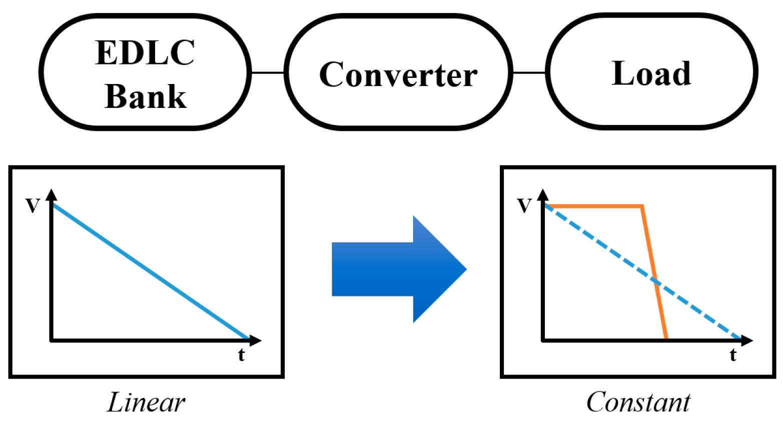
The supercapacitor standalone system can be divided into an EDLC bank and an isolated boost series-parallel resonant converter system. Figure 1 shows the fundamental concept.
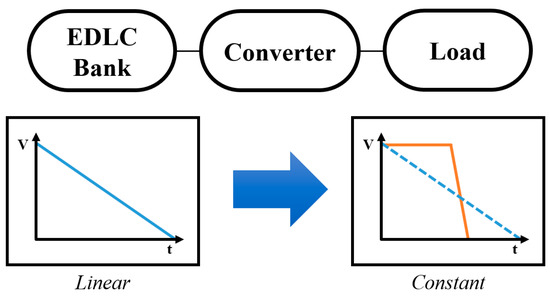
Figure 1.
Fundamental concept of mobile power charger using EDLC bank.
When discharging the energy stored in the SC bank to a load, a proposed converter is employed to transform the linear output voltage into a stable, constant voltage.
2.1. Supercapacitor Bank
The EDLC (Electric Double-Layer Capacitor), known as supercapacitor functions as a device for storing and supplying electrical energy, operating on a different principle than conventional electrochemical batteries. Supercapacitors store charge not through electrochemical reactions but by forming an electrical double layer, allowing them to store energy.
Supercapacitors provide enhanced performance and safety compared to traditional batteries, but their lower energy density results in increased storage space requirements. Table 1 displays the characteristics of the energy storage devices employed within the energy storage system.

Table 1.
Comparison of typical characteristics of energy storage devices.
During EDLC discharge to a load resistance without a DC/DC converter, the output voltage decreases rapidly. Moreover, employing a low-resistance load, typically in the range of several ohms, shortens the discharge time due to the RC time constant.
2.2. Isoltaed Boost LCC Series-Parallel Resonant Converter
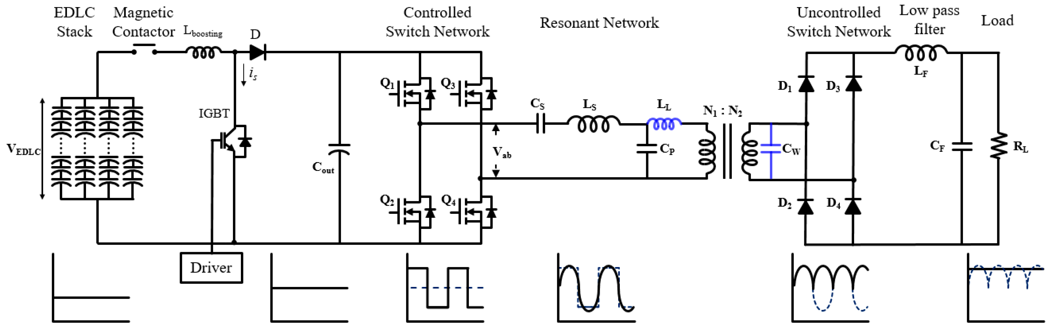
The system consists of EDLC bank voltage, an inverter (working at tens to hundreds of kHz), a high-frequency transformer, a rectifier network, an LC filter, and a load shown in Figure 2.
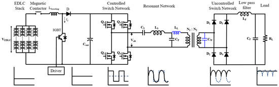
Figure 2.
Block diagram of EDLC stand-alone system-based isolated boost converter.
is the EDLC bank charged energy. EDLC is constructed according to the following equation to conduct large-scale experiments.
where and are the capacitance and the voltage of the th EDLC cell in a module of N cells. To form 233.3 Wh, 64.8 V bank to store energy, 120 EDLCs of 2.7 V, and 3000 F are connected in series by 30 modules, and four-stage modules are connected in parallel.
The thermal runaway mechanism that occurs in the battery has been comprehensively summarized in several reviews [37,38,39]. However, the behavior and mechanism of thermal propagation within battery modules or packs require further investigation, considering the intricate thermal interactions among individual cells. During thermal runaway, a substantial amount of heat is rapidly generated by the battery module, and its spread can be influenced by factors such as bus type, module structure, cell shape, electrical connections, energy levels, and heat dissipation methods. We attempted to implement this capacity and structural analysis.
A known series-parallel resonant converter (SPRC) is an LCC resonant converter. EDLC bank discharge voltage throughout isolated boost LCC SPRC. It can maintain the output voltage of the EDLC bank constant for a longer period. Therefore, the linear discharge voltage will be the constant voltage by the LCC resonant converter in wide load conditions such as light load and no load.
2.3. Isoltaed Boost LCC Series-Parallel Resonant Converter Design and Analysis
In this section, we explain the design and analysis of the LCC resonant converter using the first harmonic approximation (FHA) method [40].
The key characteristics of the developed converter are outlined below.
(1) High efficiency and voltage regulation: The developed converter was designed based on the existing boost converter and serial/parallel resonance converter. The LCC resonant converter is capable of zero voltage switching. It consists of a full bridge inverter (S1–S4), LCC resonance tanks (LS, CS, CP), a high voltage transformer (TR), a full-wave rectifier (D1–D4), and an LC filter, as shown in the Figure 2. The full bridge inverter is configured using MOSFET, and a lossless snubber capacitor is applied to reduce turn-off switching loss and for stable operation of MOSFET.
(2) High-frequency system: Electrical insulation is possible by applying a transformer to an existing converter. A transformer can be used to boost the voltage more easily than in the conventional way. In addition, the leakage inductance (LL) of the transformer can be included as a series resonance inductor (LS) and a winding capacitance (CW) as a parallel resonance capacitor (CP) in the implementation of the resonance tank, thereby reducing transformer loss and effectively reducing the number of devices.
(3) Low voltage imbalance: High voltage applications as well as fields using energy storage devices are frequently used to obtain high output voltage, requiring a constant static voltage. In particular, in the case of an energy storage device used in an electric vehicle, when the voltage supplied by the storage device drops, it poses a great risk. However, voltage supply devices using conventional transformers cause power loss and large voltage imbalance during output voltage conversion. To solve this problem, the proposed converter can be applied. The series-parallel resonance converter may include the leakage inductance and winding capacitance of the transformer in the elements of the LCC network. As illustrated in Figure 2, the transformer exhibits leakage inductance (LL), winding capacitance (CW), and various parasitic components. The LCC resonance converter can incorporate these elements into its network [41,42]. Converters designed with these characteristics offer notable benefits, including enhanced efficiency, advantages in high-frequency systems, and the ability to mitigate low voltage imbalances. Consequently, they prove valuable in a wide array of applications.
The Table 2 represents the parameters of the designed LCC network.
Table 2.
Design parameters for LCC resonant network.
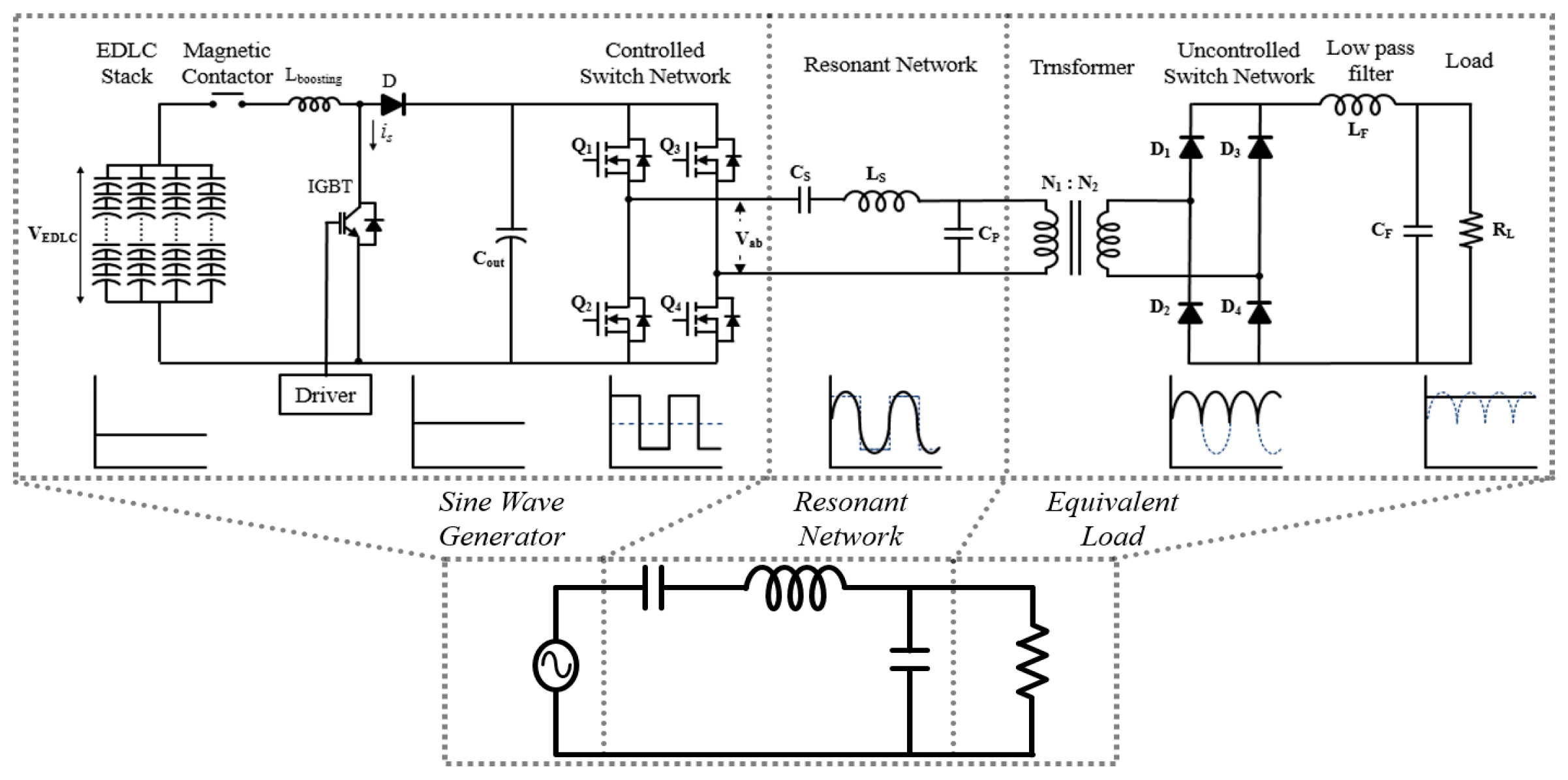
Since the improved converter is also a resonant converter, the FHA model of the LCC resonant converter can be applied to analyze the voltage gain. The topology can be equalized as a simplified circuit. This equalized simple circuit can be obtained through a mathematical model. It is shown in Figure 3.
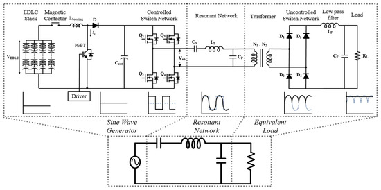
Figure 3.
Schematic of the equivalent circuit for the LCC resonant converter.
To derive a mathematical model, we employ the first harmonic approximation (FHA) method for analysis. For the sake of simplicity, we assume that all components within the resonant network and the high-frequency output rectifier are ideal. The voltage transfer function of the LCC resonant converter can be obtained using the following equation:
Another equation that can achieve the same result is as follows.
is the effective value of the fundamental component of the rectifier input voltage, and is the effective value of the fundamental component of the voltage at the input of the equivalent resonance circuit. , is the resonant frequency, and is equivalent resonant capacitor.
Impedance
Quality factor
From equation for this case
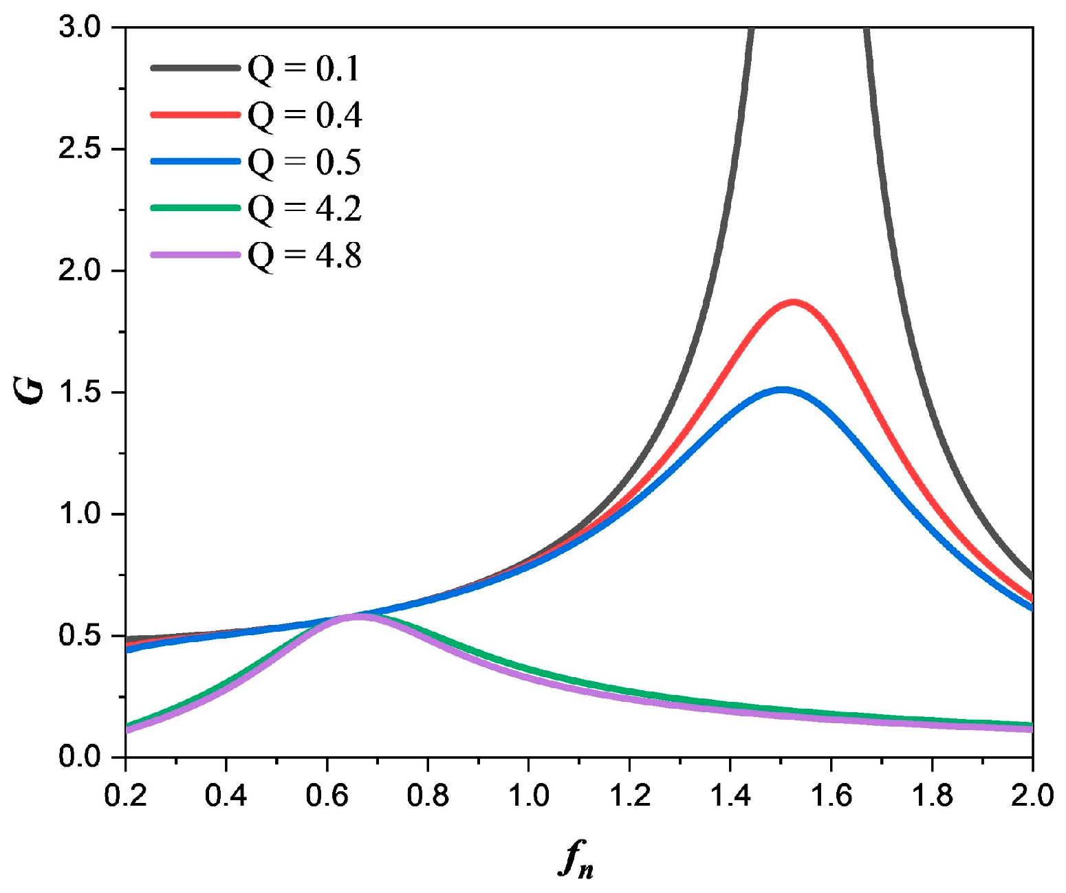
The magnitude of the AC-to-AC voltage transfer function is represented as a function of the frequency fn divided by the resonant frequency fs at various Q (quality factor) values. This process can be performed according to the flowchart to obtain a voltage transfer gain according to fn = fs/fo with different quality factors as shown Figure 4.
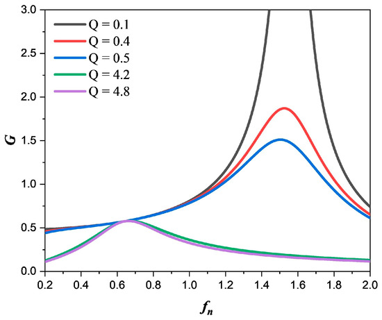
Figure 4.
Voltage gain of the LCC resonant converter as determined by the FHA (First Harmonic Approximation) model.
The load independent point is switching frequency below resonant frequency and by suitable choice of and the ratio of , it is possible to operate from no load to full load with a small range of . For this reason, it should be designed through the process shown in Figure 5.
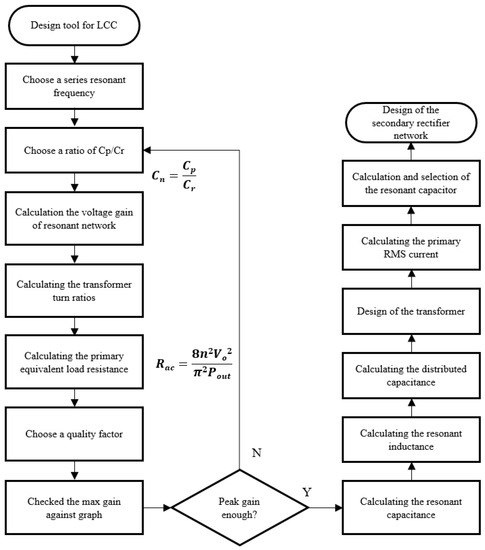
Figure 5.
Procedures to acquire voltage gain using FHA method flowchart.
To achieve high efficiency across a wide load range in the LCC resonant converter, soft switching technology is essential. This technology leads to zero voltage switching (ZVS) for the primary-side MOSFET and zero current switching (ZCS) for the secondary-side rectifier diode [43,44].
3. Description of the Experimental System Setup
The proposed system comprises two prototypes: an EDLC bank composed solely of SCs, a boost converter, and a series-parallel resonance converter integrated to convert the boosted energy by dividing it into two stages.
3.1. 233-Wh EDLC Bank
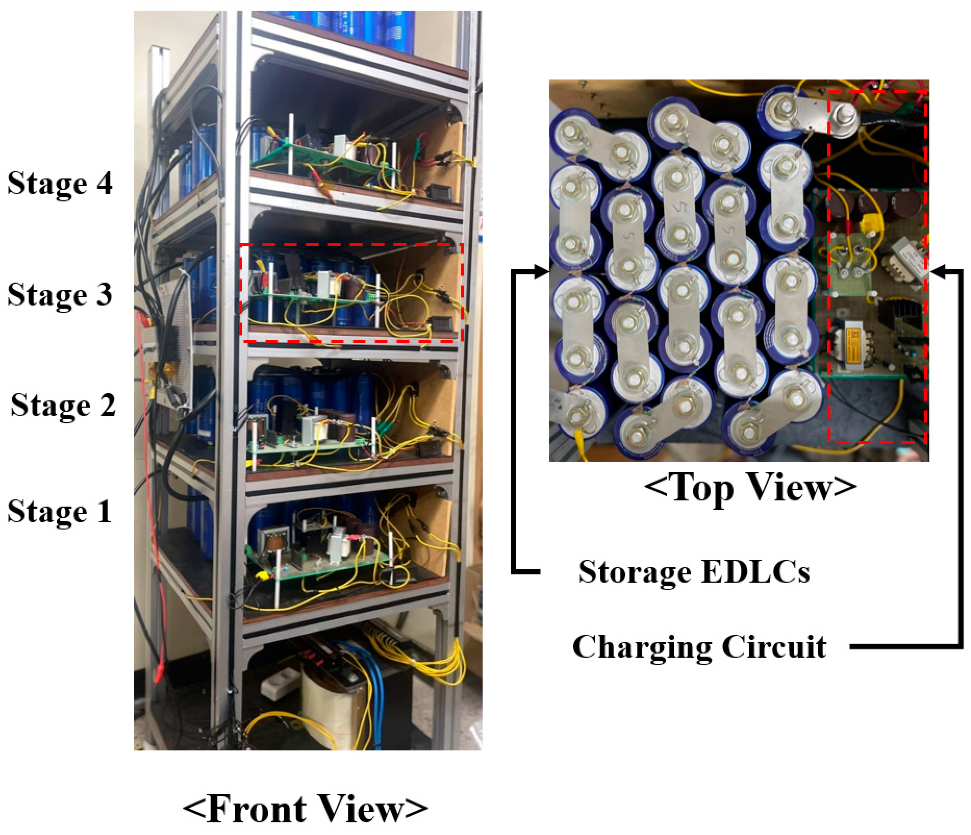
Figure 6 illustrates the configuration of the power storage system, which includes the EDLC energy storage units and the associated charging circuit. The designed EDLC bank connects 30 pieces of EDLC of 2.7 V and 3000 F in series to make modules of 81 V and 100 F. And connect the four modules in parallel in four stages to make it 400 F. At this time, 80% of the maximum rated voltage is 64.8 V when charging. At this time, 20% of the maximum rating is the safety margin presented in the specification. In addition, the total capacity is about 1/1000 scale of 250 kWh.

Figure 6.
400 F, 233.28 Wh EDLC bank.
Charging circuits are installed in each of the four modules. This charging circuit is designed to charge the module by receiving an AC voltage of 220 V and converting it into DC. Table 3 presents the components utilized in the design of this charging circuit.
Table 3.
Components of EDLC bank including charger circuit.
Figure 7 shows the output voltage when discharging the charged voltage with a load. During discharge without a DC-DC converter, the output is linear, causing the voltage to decrease proportionally with time. This is contrary to the constant output voltage until the lithium-ion battery is completely discharged at constant power.
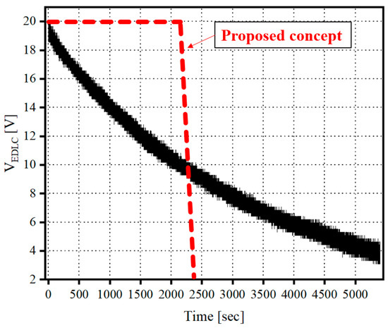
Figure 7.
Output voltage of the linearly discharging EDLC bank.
It is difficult for a supercapacitor to replace batteries such as lithium-ion batteries and be used as a single power source. Therefore, the proposed converter should be applied to make the linear output a constant output.
3.2. Isolated Boost Series-Parallel Reosnant Converter
The converter takes the voltage from the charged EDLC bank and regulates the voltage by performing another boost operation. This boost occurs after the initial increase, ensuring that the charging voltage of the EDLC remains constant despite fluctuations in the resonant network and the transformer. In this case, Digital signal process module TMS320F28335 module of Texas Instrument is used for frequency modulation.
The parameters of the components utilized in the prototype are detailed in Table 4.
Table 4.
Parameters of proposed converter parts.
To achieve the capacity to convert the linear output voltage of the EDLC into a constant output and to fulfill the requirements of a highly efficient system, a circuit divided into primary boost and secondary boost stages was constructed. The existing boost converter method was applied to the primary boost circuit, and the second boost circuit was applied with a series and parallel resonance converter.
The conventional boost converter can vary the output voltage gain by regulating the duty cycle of the switch. In this case, the efficiency decreases in proportion to the duty ratio. That is, as the voltage is boosted to a high voltage, the loss occurring in the circuit increases. This adversely affects the use of stored energy.
In this paper, we validated the performance of the designed system through experiments. To a certain extent, system efficiency is improved, and complicated control is avoided, which can prove the stable operation of the proposed system. In addition, the proposed converter can be applied with a transformer, which can electrically insulate DC power and load.
4. Experimental Results
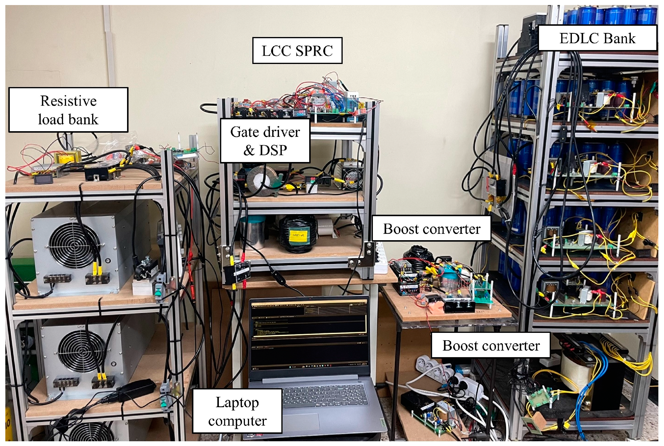
Figure 8 illustrates the experimental environment in which the experiment was conducted. The voltage of the EDLC bank charged with commercial 220 VAC is transmitted to the load bank through the primary boost converter and secondary LCC series-parallel resonance converter (LCC SPRC).

Figure 8.
Photograph of the prototype experimental setup.
4.1. Constant Voltage Output with Supercapacitor Bank
To validate the efficiency and design of the isolated boost series-parallel resonant converter, a 10 kW prototype with a 20~0 VDC input and 20 V output was constructed and subjected to testing. Our primary focus was on assessing the ability of the converter to maintain a constant output voltage under varying load conditions for an extended duration.
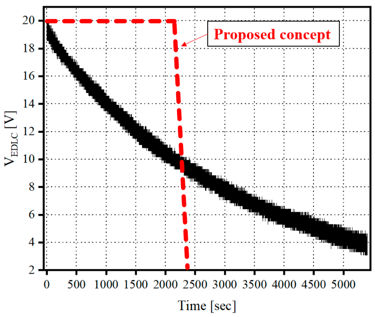
Figure 9 shows the waveform of the output voltage when discharged through the insolated boost series-parallel resonant converter manufactured, which is the result of charging the EDLC bank to 20 V through the charging circuit and discharging it with a load. At this time, the converter allowed the constant output voltage to be obtained from the linear output voltage of the EDLC. It successfully maintained a constant output voltage equivalent to 98.1% of the linear output voltage from the EDLC bank. The discharge time was 2750 s (about 45.8 min).
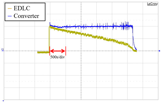
Figure 9.
Output waveform when discharging with the proposed converter.
The output voltage waveform when the voltage from the EDLC bank is discharged directly to the load bank without the use of a converter. It is a linear output voltage, which is discharged for 8000 s (about 133 min).
The contrasting outcomes between these two results can be attributed to the utilization of the proposed converter. With the converter in place, the EDLC bank achieved a stable output voltage, and the discharge time of stored energy was notably reduced, by approximately 34.4%, from 8000 s to 2750 s.
Under light load, where the output is low, power loss mainly stems from switching and conduction losses. Switching losses occur during switch and diode operation, while conduction losses result from internal resistances. Since light load leads to low output, significant switching losses can lower efficiency. At rated load, the converter nearly matches its supplied rated output. Here, switching and conduction losses are minimized, resulting in higher efficiency due to lower losses.
An experiment was conducted to validate the efficiency of the proposed converter, which is capable of maintaining a consistent output voltage despite fluctuations in the load conditions. Figure 10 illustrates how the output voltage waveform of the EDLC bank evolves under different load conditions. Depending on the load variations of the load bank, the linear voltage of the EDLC bank changes at varying discharge rates. In this scenario, the charging voltage of the EDLC bank remains at 30 V, but the load conditions change when the charging voltages are set to 25 V and 10 V.
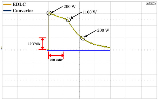
Figure 10.
Changes in linear voltage output of the EDLC bank according to changes in load condition.
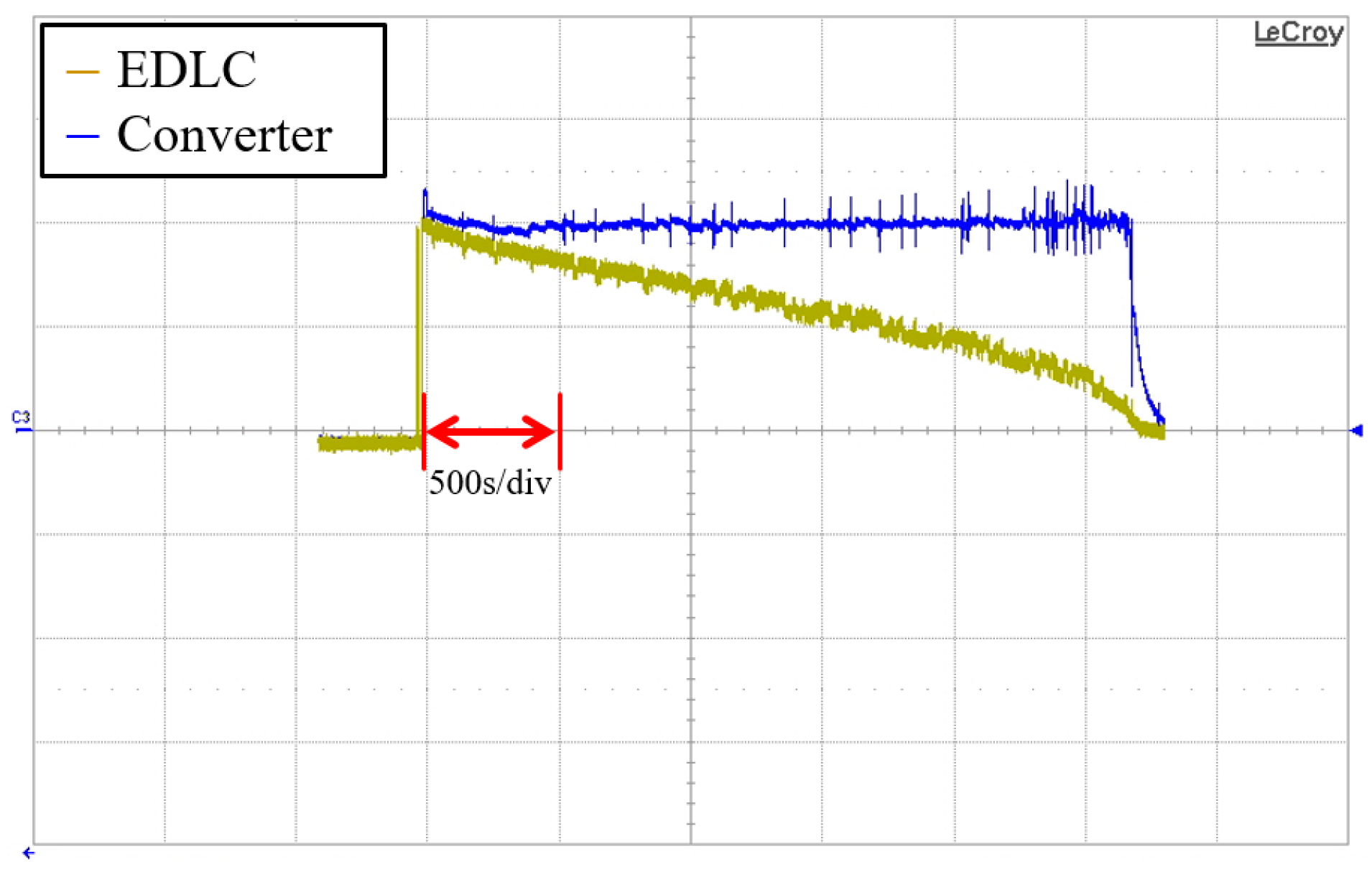
Figure 11 shows that the proposed converter can produce a constant output voltage even with a change in load condition. The EDLC bank was linearly charged at 30 V for 400 s (6.7 min) and discharged at constant voltage for about 1040 s (17 min) through a converter. This converter maintained the constant output voltage for 880 s out of the discharge time of 1040 s. It is 84.6 percent.
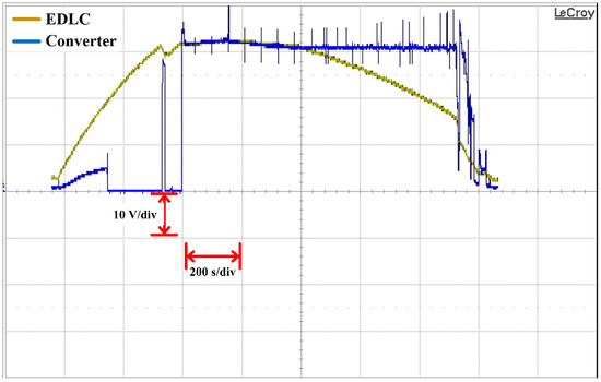
Figure 11.
Discharge voltage of the SPRC converter-based EDLC during load state change.
4.2. Efficiency Comparison and Analysis
High efficiency is important for the converter to maintain a constant output. Losses may occur on the switches and the secondary switches and the transformers on one primary boost circuit, as indicated. This section compares the efficiency of the proposed converter circuit and analyzes the loss with motion.
During the operation of the designed converter, the magnitudes of the voltages across the series and parallel capacitors, as well as the current flowing through the inductor, were observed. This provided insights into the magnitude of the amplified voltage within the LCC network.
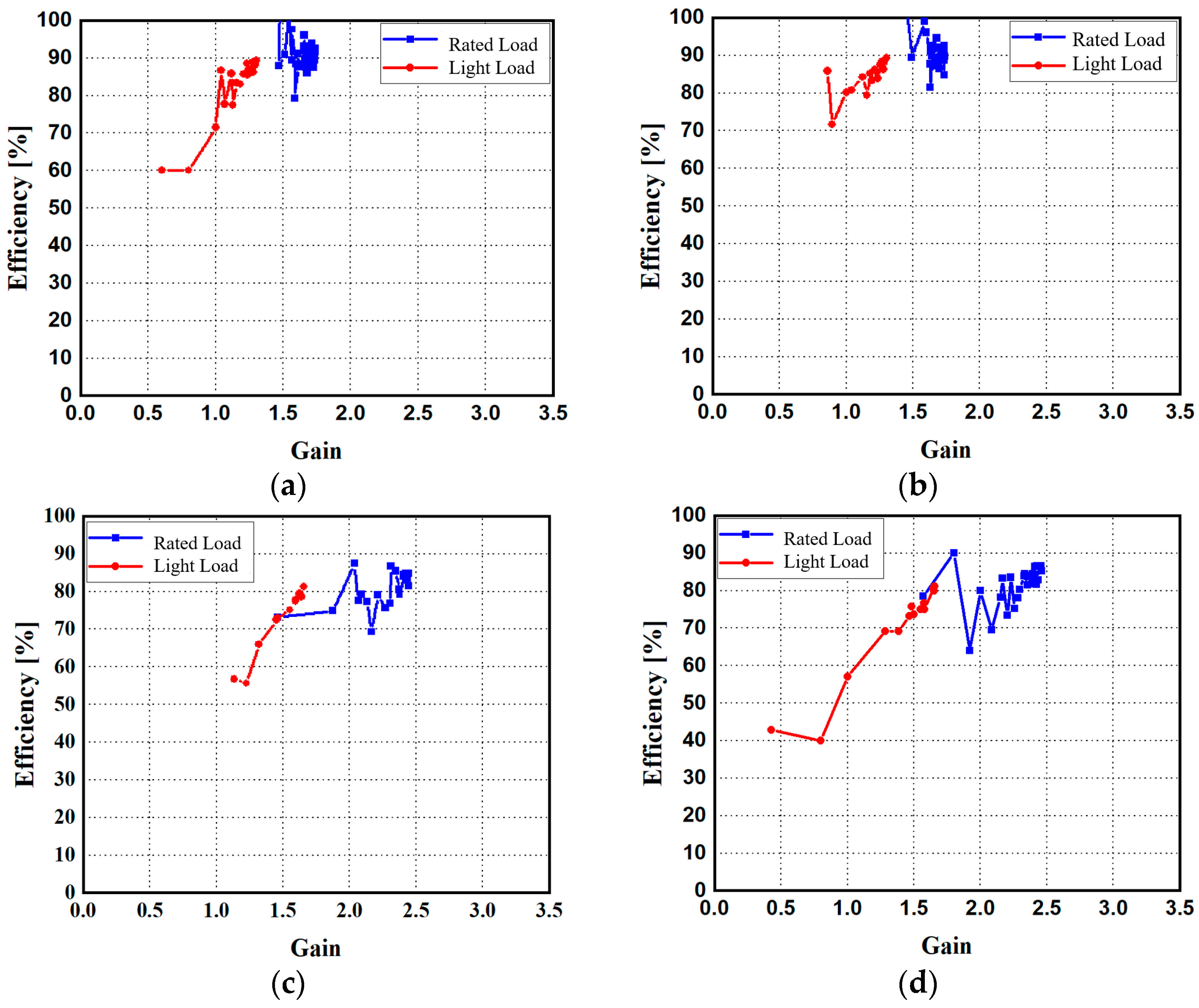
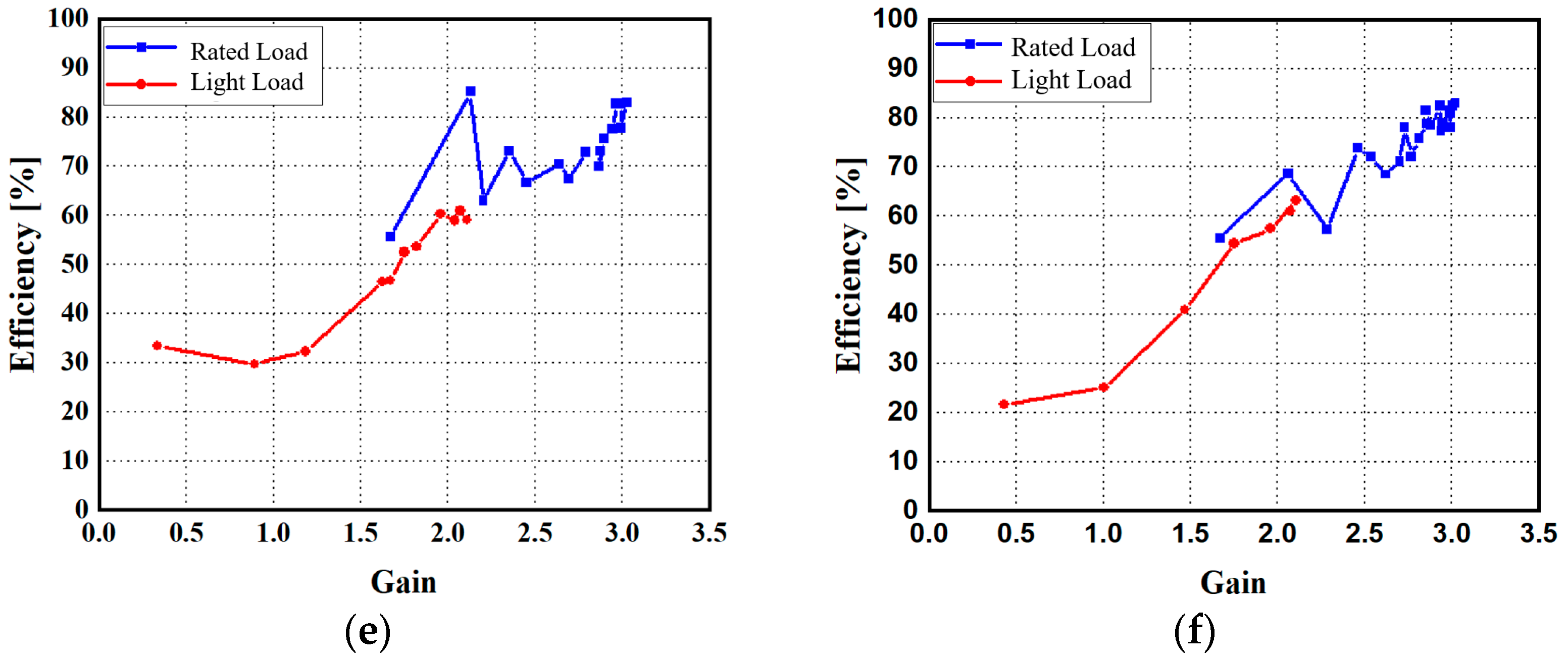
Figure 12 is a comparison of the proposed Isolated Boost LCC series-parallel resonance converter (a), (c) and (e) with the existing LCC series resonance converter methods (b), (d) and (f). These efficiency results are based on the relationship between the designed resonance frequency and the actual operating switching frequency. The closer to the designed resonance point, the difference in efficiency according to the load is as follows.
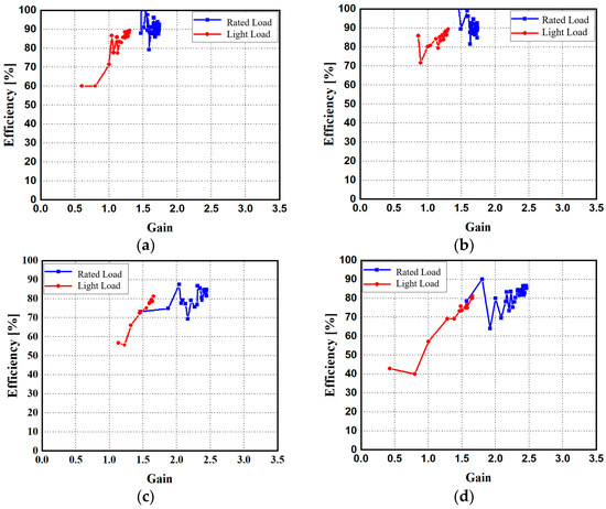
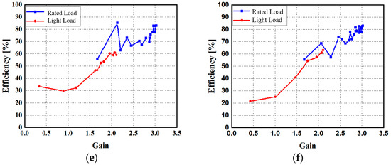
Figure 12.
Comparing the efficiency of the proposed converters (a,c,e) with that of the existing LCC converters (b,d,f).
Both of the measured converters conducted the experiment within the optimal distance of the resonance point. The efficiency of the LCC series-parallel resonance converter increases near the resonance point. In the resonance state, the reactive components of the circuit, the inductors, and capacitors, are naturally balanced to minimize the reactive power exchange between the input and output. This reduces the loss of reactive components and improves overall efficiency. Therefore, the energy between the input and output of the reactive components of the LCC network must be designed to be efficiently stored and exchanged to ensure an optimal energy conversion process, thus increasing efficiency. In addition, small transmission power losses in the circuit, such as diodes, transistors, and inductors, are also reduced near the resonance point. However, operating too close to the resonance point can be sensitive to small load changes or minor changes in component values. In certain situations, instability can sometimes occur, affecting overall efficiency and performance.
The experimental results confirm the validity of the theoretical derivation for the supercapacitor bank system utilizing the Isolated boost LCC series-parallel resonant converter. These experiments are instrumental in implementing an effective discharge strategy.
5. Conclusions
In this paper, a high-efficiency EDLC bank’s energy discharge to load using LCC resonant converter is proposed that delivers 233.3 Wh, 64.8 V to the load that different conditions such as no load and light load. This paper showcases the experimental findings of the EDLC bank integrated with the proposed converter, achieving a constant output ratio of 84.6% while effectively covering a wide range of load conditions as intended.
This experiment substantiated the efficacy of the proposed converter. The proposed system offers several advantages:
- The converter ensures a constant output with a supercapacitor bank.
- The isolated boost LCC series-parallel resonant converter operates at high frequency and employs a frequency modulation technique.
- ZVS (Zero Voltage Switching) conditions for the inverter-side MOSFET can be achieved through resonance parameters.
The effectiveness of the isolated boost LCC series-parallel resonant converter has been verified through the 10 kW prototype. The experimental results demonstrate that the proposed converter can maintain a constant voltage while discharging the supercapacitor bank, thus validating its functionality.
Author Contributions
Author Contributions: Conceptualization, H.-W.K.; Methodology, H.-W.K.; Formal analysis, H.-W.K.; Investigation, H.-S.L.; Resources, H.-S.L. and K.-A.L.; Writing—original draft, H.-W.K.; Writing—review & editing, K.-A.L. and J.-H.R.; Supervision, K.-A.L.; Funding acquisition, J.-H.R. All authors have read and agreed to the published version of the manuscript.
Funding
This work was supported by the National Research Foundation of Korea(NRF) grant funded by the Korea government(MSIT) (No. RS-2022-00166064).
Data Availability Statement
Data available on request due to restrictions eg privacy or ethical The data presented in this study are available on request from the corresponding author. The data are not publicly available due to [The data are not publicly available due to the fact that they are necessary for forthcoming manuscript submissions and ongoing research projects].
Conflicts of Interest
The authors declare no conflict of interest.
References
- Rani, J.R.; Thangavel, R.; Oh, S.-I.; Woo, J.M.; Chandra Das, N.; Kim, S.-Y.; Lee, Y.-S.; Jang, J.-H. High volumetric energy density hybrid supercapacitors based on reduced graphene oxide scrolls. ACS Appl. Mater. Interfaces 2017, 9, 22398–22407. [Google Scholar] [CrossRef]
- Liu, C.; Li, F.; Ma, L.P.; Cheng, H.M. Advanced materials for energy storage. Adv. Mater. 2010, 22, E28–E62. [Google Scholar] [CrossRef]
- Miller, J.R.; Simon, P. Electrochemical capacitors for energy management. Science 2008, 321, 651–652. [Google Scholar] [CrossRef] [PubMed]
- Simon, P.; Gogotsi, Y. Materials for electrochemical capacitors. In Nanoscience and Technology: A Collection of Reviews from Nature Journals; World Scientific: Singapore, 2010; pp. 320–329. [Google Scholar]
- Chidembo, A.; Aboutalebi, S.H.; Konstantinov, K.; Salari, M.; Winton, B.; Yamini, S.A.; Nevirkovets, I.P.; Liu, H.K. Globular reduced graphene oxide-metal oxide structures for energy storage applications. Energy Environ. Sci. 2012, 5, 5236–5240. [Google Scholar] [CrossRef]
- Cheng, X.; Li, T.; Ruan, X.; Wang, Z. Thermal runaway characteristics of a large format lithium-ion battery module. Energies 2019, 12, 3099. [Google Scholar] [CrossRef]
- Kaempgen, M.; Chan, C.K.; Ma, J.; Cui, Y.; Gruner, G. Printable thin film supercapacitors using single-walled carbon nanotubes. Nano Lett. 2009, 9, 1872–1876. [Google Scholar] [CrossRef]
- Chen, Z.; Wen, J.; Yan, C.; Rice, L.; Sohn, H.; Shen, M.; Cai, M.; Dunn, B.; Lu, Y. High-performance supercapacitors based on hierarchically porous graphite particles. Adv. Energy Mater. 2011, 1, 551–556. [Google Scholar] [CrossRef]
- Chen, M.; Sun, Q.; Li, Y.; Wu, K.; Liu, B.; Peng, P.; Wang, Q. A thermal runaway simulation on a lithium titanate battery and the battery module. Energies 2015, 8, 490–500. [Google Scholar] [CrossRef]
- Tian, X.; Yi, Y.; Fang, B.; Yang, P.; Wang, T.; Liu, P.; Qu, L.; Li, M.; Zhang, S. Design strategies of safe electrolytes for preventing thermal runaway in lithium ion batteries. Chem. Mater. 2020, 32, 9821–9848. [Google Scholar] [CrossRef]
- Liu, X.; Zhou, Z.; Wu, W.; Gao, L.; Li, Y.; Huang, H.; Huang, Z.; Li, Y.; Song, Y. Three-dimensional modeling for the internal shorting caused thermal runaway process in 20AH lithium-ion battery. Energies 2022, 15, 6868. [Google Scholar] [CrossRef]
- Qian, F.; Wang, H.; Li, M.; Li, C.; Shen, H.; Wang, J.; Li, Y.; Ouyang, M. Thermal Runaway vent gases from high-capacity energy storage LiFePO4 lithium iron. Energies 2023, 16, 3485. [Google Scholar] [CrossRef]
- Wang, D.; Zheng, L.; Li, X.; Du, G.; Zhang, Z.; Feng, Y.; Jia, L.; Dai, Z. Effects of overdischarge rate on thermal runaway of NCM811 Li-ion batteries. Energies 2020, 13, 3885. [Google Scholar] [CrossRef]
- Ghiji, M.; Novozhilov, V.; Moinuddin, K.; Joseph, P.; Burch, I.; Suendermann, B.; Gamble, G. A review of lithium-ion battery fire suppression. Energies 2020, 13, 5117. [Google Scholar] [CrossRef]
- Ehsani, M.; Gao, Y.; Miller, J.M. Hybrid electric vehicles: Architecture and motor drives. Proc. IEEE 2007, 95, 719–728. [Google Scholar] [CrossRef]
- Tan, N.M.; Inoue, S.; Kobayashi, A.; Akagi, H. Voltage balancing of a 320-V, 12-F Electric Double-Layer Capacitor bank combined with a 10-kW bidirectional isolated DC--DC converter. IEEE Trans. Power Electron. 2008, 23, 2755–2765. [Google Scholar] [CrossRef]
- Ali, A.; Shakoor, R.; Raheem, A.; Muqeet, H.A.U.; Awais, Q.; Khan, A.A.; Jamil, M. Latest energy storage trends in multi-energy standalone electric vehicle charging stations: A comprehensive study. Energies 2022, 15, 4727. [Google Scholar] [CrossRef]
- Ibanez, F.M. Analyzing the need for a balancing system in supercapacitor energy storage systems. IEEE Trans. Power Electron. 2017, 33, 2162–2171. [Google Scholar] [CrossRef]
- Forouzandeh, P.; Kumaravel, V.; Pillai, S.C. Electrode materials for supercapacitors: A review of recent advances. Catalysts 2020, 10, 969. [Google Scholar] [CrossRef]
- Atmaja, T.D.; Mirdanies, M. Electric vehicle mobile charging station dispatch algorithm. Energy Procedia 2015, 68, 326–335. [Google Scholar] [CrossRef]
- Cui, S.; Zhao, H.; Chen, H.; Zhang, C. The mobile charging vehicle routing problem with time windows and recharging services. Comput. Intell. Neurosci. 2018, 2018, 5075916. [Google Scholar] [CrossRef]
- Afshar, S.; Macedo, P.; Mohamed, F.; Disfani, V. A literature review on mobile charging station technology for electric vehicles. In Proceedings of the 2020 IEEE Transportation Electrification Conference & Expo (ITEC), Chicago, IL, USA, 23–26 June 2020; pp. 1184–1190. [Google Scholar]
- Ye, B.; Jiang, J.; Miao, L.; Yang, P.; Li, J.; Shen, B. Feasibility study of a solar-powered electric vehicle charging station model. Energies 2015, 8, 13265–13283. [Google Scholar] [CrossRef]
- Saboori, H.; Jadid, S.; Savaghebi, M. Optimal management of mobile battery energy storage as a self-driving, self-powered and movable charging station to promote electric vehicle adoption. Energies 2021, 14, 736. [Google Scholar] [CrossRef]
- Gomez Vidales, A.; Sridhar, D.; Meunier, J.-L.; Omanovic, S. Nickel oxide on directly grown carbon nanofibers for energy storage applications. J. Appl. Electrochem. 2020, 50, 1217–1229. [Google Scholar] [CrossRef]
- Gomez Vidales, A.; Kim, J.; Omanovic, S. Ni0.6−xMo0.4−xIrx-oxide as an electrode material for supercapacitors: Investigation of the influence of iridium content on the charge storage/delivery. J. Solid State Electrochem. 2019, 23, 2129–2139. [Google Scholar] [CrossRef]
- Pernía, A.M.; Prieto, M.J.; Villegas, P.J.; Díaz, J.; Martín-Ramos, J.A. LCC resonant multilevel converter for X-ray applications. Energies 2017, 10, 1573. [Google Scholar] [CrossRef]
- Martín-Ramos, J.A.; Sáiz, P.J.V.; Pernía, A.M.; Díaz, J.; Martínez, J.A. Optimal control of a high-voltage power supply based on the PRC-LCC topology with a capacitor as output filter. IEEE Trans. Ind. Appl. 2013, 49, 2323–2329. [Google Scholar] [CrossRef]
- Ivensky, G.; Kats, A.; Ben-Yaakov, S. An RC load model of parallel and series-parallel resonant DC-DC converters with capacitive output filter. IEEE Trans. Power Electron. 1999, 14, 515–521. [Google Scholar] [CrossRef]
- Diaz, J.; Saiz, P.J.V.; Martin-Ramos, J.A.; Martin-Pernia, A.; Martinez, J.A. A high-voltage AC/DC resonant converter based on PRC with single capacitor as an output filter. IEEE Trans. Ind. Appl. 2010, 46, 2134–2142. [Google Scholar] [CrossRef]
- Kobaku, T.; Jeyasenthil, R.; Sahoo, S.; Ramchand, R.; Dragicevic, T. Quantitative feedback design-based robust PID control of voltage mode controlled DC-DC boost converter. IEEE Trans. Circuits Syst. II Express Briefs 2020, 68, 286–290. [Google Scholar] [CrossRef]
- Merai, M.; Naouar, M.W.; Slama-Belkhodja, I. An improved DC-link voltage control strategy for grid connected converters. IEEE Trans. Power Electron. 2017, 33, 3575–3582. [Google Scholar] [CrossRef]
- Wang, L.; Wu, Q.; Tao, Y.; Tang, W. Switching control of buck converter based on energy conservation principle. IEEE Trans. Control Syst. Technol. 2016, 24, 1779–1787. [Google Scholar] [CrossRef]
- Baek, J.-E.; Rhee, J.-H.; Ko, K.-C. Hybrid analog and digital control of a high current converter based on an EDLC Bank for rapidly decreasing input voltage. IEEE Trans. Plasma Sci. 2018, 47, 542–548. [Google Scholar] [CrossRef]
- Zhang, L.; Li, H.; Guo, Q.; Xie, S.; Yang, Y. Research on constant voltage/current output of LCC–S envelope modulation wireless power transfer system. Energies 2022, 15, 1562. [Google Scholar] [CrossRef]
- Yang, J.; Zhang, X.; Zhang, K.; Cui, X.; Jiao, C.; Yang, X. Design of LCC-S compensation topology and optimization of misalignment tolerance for inductive power transfer. IEEE Access 2020, 8, 191309–191318. [Google Scholar] [CrossRef]
- Feng, X.; Ouyang, M.; Liu, X.; Lu, L.; Xia, Y.; He, X. Thermal runaway mechanism of lithium ion battery for electric vehicles: A review. Energy Storage Mater. 2018, 10, 246–267. [Google Scholar] [CrossRef]
- Ruiz, V.; Pfrang, A.; Kriston, A.; Omar, N.; Van den Bossche, P.; Boon-Brett, L. A review of international abuse testing standards and regulations for lithium ion batteries in electric and hybrid electric vehicles. Renew. Sustain. Energy Rev. 2018, 81, 1427–1452. [Google Scholar] [CrossRef]
- Wang, Q.; Ping, P.; Zhao, X.; Chu, G.; Sun, J.; Chen, C. Thermal runaway caused fire and explosion of lithium ion battery. J. Power Source 2012, 208, 210–224. [Google Scholar] [CrossRef]
- Steigerwald, R.L. A comparison of half-bridge resonant converter topologies. IEEE Trans. Power Electron. 1988, 3, 174–182. [Google Scholar] [CrossRef]
- Biela, J.; Kolar, J.W. Using transformer parasitics for resonant converters-a review of the calculation of the stray capacitance of transformers. In Proceedings of the Fourtieth IAS Annual Meeting. Conference Record of the 2005 Industry Applications Conference, Hong Kong, China, 2–6 October 2005; pp. 1868–1875. [Google Scholar]
- Kolahian, P.; Grimm, F.; Baghdadi, M. A comprehensive review on planar magnetics and the structures to reduce the parasitic elements and improve efficiency. Energies 2023, 16, 3254. [Google Scholar] [CrossRef]
- Li, H.; Zhang, Z.; Wang, S.; Tang, J.; Ren, X.; Chen, Q. A 300-kHz 6.6-kW SiC bidirectional LLC onboard charger. IEEE Trans. Ind. Electron. 2019, 67, 1435–1445. [Google Scholar] [CrossRef]
- Kundu, U.; Yenduri, K.; Sensarma, P. Accurate ZVS analysis for magnetic design and efficiency improvement of full-bridge LLC resonant converter. IEEE Trans. Power Electron. 2016, 32, 1703–1706. [Google Scholar] [CrossRef]


Disclaimer/Publisher’s Note: The statements, opinions and data contained in all publications are solely those of the individual author(s) and contributor(s) and not of MDPI and/or the editor(s). MDPI and/or the editor(s) disclaim responsibility for any injury to people or property resulting from any ideas, methods, instructions or products referred to in the content. |
© 2023 by the authors. Licensee MDPI, Basel, Switzerland. This article is an open access article distributed under the terms and conditions of the Creative Commons Attribution (CC BY) license (https://creativecommons.org/licenses/by/4.0/).