Review

A Review of Powertrain Electrification for Greener Aircraft

Laplace (UMR CNRS-Toulouse INP-UPS), Université de Toulouse, ENSEEIHT 2 Rue Camichel, 31071 Toulouse, France
Energies 2023, 16(19), 6831; https://doi.org/10.3390/en16196831
Submission received: 26 May 2023 / Revised: 24 July 2023 / Accepted: 28 August 2023 / Published: 26 September 2023
(This article belongs to the Section E: Electric Vehicles)

Abstract

:
This review proposes an overview of hybrid electric and full electric powertrains dedicated to greener aircraft in the “sky decarbonization” context. After having situated the state of the art and context of energy hybridization in the aviation sector, we propose the visit of several architectures for powertrain electrification, situating the potential benefits but also the main challenges to be faced to takeoff these new solutions. Then, as a first example, we consider the EU project “HASTECS” (Hybrid Aircraft: reSearch on Thermal and Electric Components and Systems) in the framework of Clean Sky 2. It relates to a series hybrid chain integrated into a regional aircraft. This energy system integrates especially power electronics and electric machines with a high degree of integration, which raises the “thermal challenge” and the need to integrate cooling devices. Through the snowball effects typical of the aviation sector, this example emphasizes how important it is to “hunt for kilos”, an alternative solution consisting of eliminating the power electronics within the powertrain. This is why we propose a second example, which concerns an AC power channel without power electronics that only integrates synchronous magnet machines (generator and motor) directly coupled on an AC bus. This last architecture nevertheless raises questions in terms of stability, with one solution being to insert an auxiliary hybridization branch via battery storage. Theoretical analyses and experiments at a reduced power scale show the viability of this concept. Finally, some recommendations for future research with potential technological breakthroughs complete that review.

1. Introduction

The transportation sector is strongly contributing to gas emissions. It is then essential to find sustainable solutions to reduce environmental degradation. This is particularly important for the aviation sector, which is responsible for around 2–3% of CO2 emissions.
The COVID-19 crisis has provoked a huge slowdown of the air traffic progression, but the huge trend towards growing traffic is resilient to successive crises: if the International Air Transport Association (IATA) 2022 forecast is realized, traffic would still be 6% below the pre-pandemic forecast [1], as illustrated in Figure 1. This trend is confirmed according to Eurocontrol analysis and forecast [2], showing that the air traffic has reached 86% of pre-pandemic (2019) traffic by August 2022, with the pre-pandemic recovery probably reached between 2023 and 2025 according to low or high scenarios.
This growth in air traffic is likely to provoke an increase in greenhouse gas emissions (in particular CO2) from this sector if no drastic measures are envisaged. Current measures only slightly increase the efficiency of conventional systems and will not be sufficient to achieve the ambitious decarbonization targets announced by the IATA: “to reduce greenhouse gas emissions by 50% in 2050 with reference to 2005”. To achieve this goal, several scenarios, one of which is illustrated in Figure 2, are based on a set of measures, among which the development of new-generation technologies for aviation is prominent [3].

1.1. Literature Review on Electrically Propelled Aircraft

In that context, the aviation sector actually progresses towards more electric aircraft [4,5,6,7,8,9,10]. As illustrated in Figure 3, numerous projects for electrified aircraft have taken off recently [5]. While well-known industrial companies (Airbus, Boeing, Rolls Royce, Safran, etc.) support some of these projects, many others are driven by start-ups or “young companies” in the aeronautical sector, as illustrated in Figure 4.
United Technologies Advanced Projects (UTAP) linked with UTC Aerospace has embarked on the electrification of aircraft with a parallel hybrid powertrain including a downsized (50%) gas turbine associated with a 1 MW auxiliary electric source. NASA was also active with the “X-57 LEAPTECH” project, investigating an aircraft with distributed propulsion [11]; however, it has very recently (i.e., Paris Air Show, June 2023) announced the project abandonment due to the low maturity and availability of electric devices in the powertrain. However, the project has demonstrated major advances in distributed electric propulsion. In France, ONERA [12,13] also studies the same kinds of distributed propulsion concepts with aerodynamic optimization, for example, “Dragon”, a partial turboelectric with BLI (boundary layer ingestion) and distributed propulsion concepts, or “Ampere”. So far, most hybrid-electric aircraft are powered by batteries. However, hydrogen solutions for fuel cells ICEs (internal combustion engines) should also be considered to progress towards greener aircraft, as announced by Airbus with its three zero-emission-aircraft concepts (Turboprop @100 pax–1000 nm, Turbofan @ 100 pax–2000 nm, and Blended wing body @ 200 pax–2000 nm). The reader can find a more detailed report on the state of the art in hybrid-electric and full-electric aircraft concepts in [14].
Based on these recent studies and feedback, the potential gains of electrification, whether it be a more electric (hybrid) or all-electric, battery or fuel cell architecture, affect the aerodynamics and energy efficiency of aircraft (engine and powertrain). This dual gain objective, summarized in Section 2, suggests a reduction in polluting emissions, particularly CO2.
Hybrid-electric- and full-electric-propulsion concepts both require new technologies and management strategies. These progress have to be integrated into hybrid-electric and full-electric powertrains in order to enhance aircraft performance, especially efficiency. Electric solutions reduce fossil source demand and lower aircraft greenhouse gas emissions and the environmental footprint of future aircraft [10,11,12,13,14,15,16,17,18,19,20,21,22,23,24,25,26]. A review of the technological challenges hampering the road toward more electric aircraft powertrains is proposed in [27]. However, compared with thermal-source solutions, electric power generally involves a weight increase on board, making power integration a critical issue [10]. A heavier embedded weight needs more wing surface and even more power to fly the aircraft; this is the “snowball effect” typically addressed in aviation. In [10], an aircraft fully equipped with thermal engines was considered as a “reference aircraft” to assess weight increase due to snowball effects and its consequences on the fuel consumption. Figure 5 shows a comparison between three conventional aircraft (with thermal engines only) with three different payloads (6500/8500/10,500 kg). It shows that adding 1 embedded ton would lead to +6.5% max take-off weight (MTOW) and 6% additional fuel burn.
Consequently, new integrated technological solutions for enhancing both efficiencies and the specific power and energy of aircraft devices are needed. This firstly requires optimizing the aircraft at a component (technology) level. However, a “system-level optimization” is also essential. The left part of Figure 6 illustrates major couplings that make the integrated optimization at the aircraft level very complex, while the right part of this figure illustrates an “extreme situation” obtained through local optimizations. To tackle these issues, multidisciplinary design optimization (MDO) approaches that investigate aircraft architecture optimization with new technologies of components are relevant. As illustrated in Figure 6, such ideas have been promoted for complex system optimization involving multiple fields of disciplines and various design levels, from elementary components to the whole system [28,29,30,31,32,33,34,35,36,37,38,39,40].
However, MDOs are generally based on rough models often centred around specific power and energies (i.e., kW/kg, kWh/kg) to simultaneously integrate the aircraft architecture with the powertrain and the aerodynamic structure design inside the MDO process. MDO approaches based on technological assessments are seldom used. Some studies focus on specific aspects of the electrified powertrain, for example, filtering stages [15] or electric machines [16]. Certain authors analyse sizing and flight mission interactions [20] or the influence of the EMS (energy management strategy) on the hybrid-electric-aircraft performance [28,29]. An MDO example of a regional aircraft with a series hybrid-electric powertrain is detailed in Section 3. Models integrated into the MDO are based on technological assessments. The system optimization also integrates the EMS assessed over typical flight missions.

1.2. Main Issues in the Review

In Section 2, this review sets the context of aircraft electrification, synthesizing its potential gains in terms of aerodynamics, engine optimization, and energy efficiency of the powertrain. By defining indicators that determine the hybridization difficulty, a comparison of aviation with other transport modes (railway, boats, and electric cars) is proposed, emphasizing the specificities of aircraft hybridization. Then, a classification of the main hybrid-electric and electric architectures is reviewed. Finally, a review of the state of the art in hybrid-electric and full-electric powertrains for recent and future aircraft is proposed.
In Section 3, the first example is explored dealing with the optimal design of the propulsion chain of a series of hybrid regional aircraft coupling thermal engines (gas turbines) and fuel cells. Technological models are “embedded” in an MDO process. Two target technologies with different levels of assessments are considered in the MDO for electrical and thermal components which progressively forecast the technological progress. The work was performed in the EU project “HASTECS” for “Hybrid Aircraft: Academic Research on Thermal and Electric Components and Systems”. In HASTECS, several technological innovations were proposed [41,42,43,44,45,46,47,48,49,50,51,52] for power electronics with high-performance cooling. Optimization tends to enhance the voltage bus involving insulation challenges with partial discharge occurrences. These innovative concepts are applied to a series of hybrid architectures beyond the “MW” and beyond the “kV” for the “ultra-HVDC” (high-voltage DC) bus, which interfaces powertrain devices through power electronics.
However, while the previous example emphasizes how important it is to “hunt for kilos”, a clear solution consists in eliminating power electronics within the powertrain; this is what we propose in the second example of Section 4, which concerns an AC power channel without power electronics, only integrating permanent magnet synchronous machines (generator and motor) directly coupled on an AC bus. This last architecture, nevertheless, raises questions in terms of stability, one solution being to insert an auxiliary hybridization branch via battery storage to stabilize the transient operation. Theoretical analyses and an experiment at a reduced power scale show the viability of this concept. This kind of hybrid structure was also proposed in [53], but for a non-propulsive electric network. In that study, a generator associated with a diode rectifier was coupled through an HVDC bus with a hybridization branch composed of a DC-DC bidirectional converter powered by a battery. An integrated control was synthesized to ensure channel stability.

2. Context of Electrically Propelled Aircraft

2.1. Potential Benefits in Terms of Engine Optimization, Aerodynamics, and Energy Efficiency

Various benefits are potentially brought by propelling electrification:
-
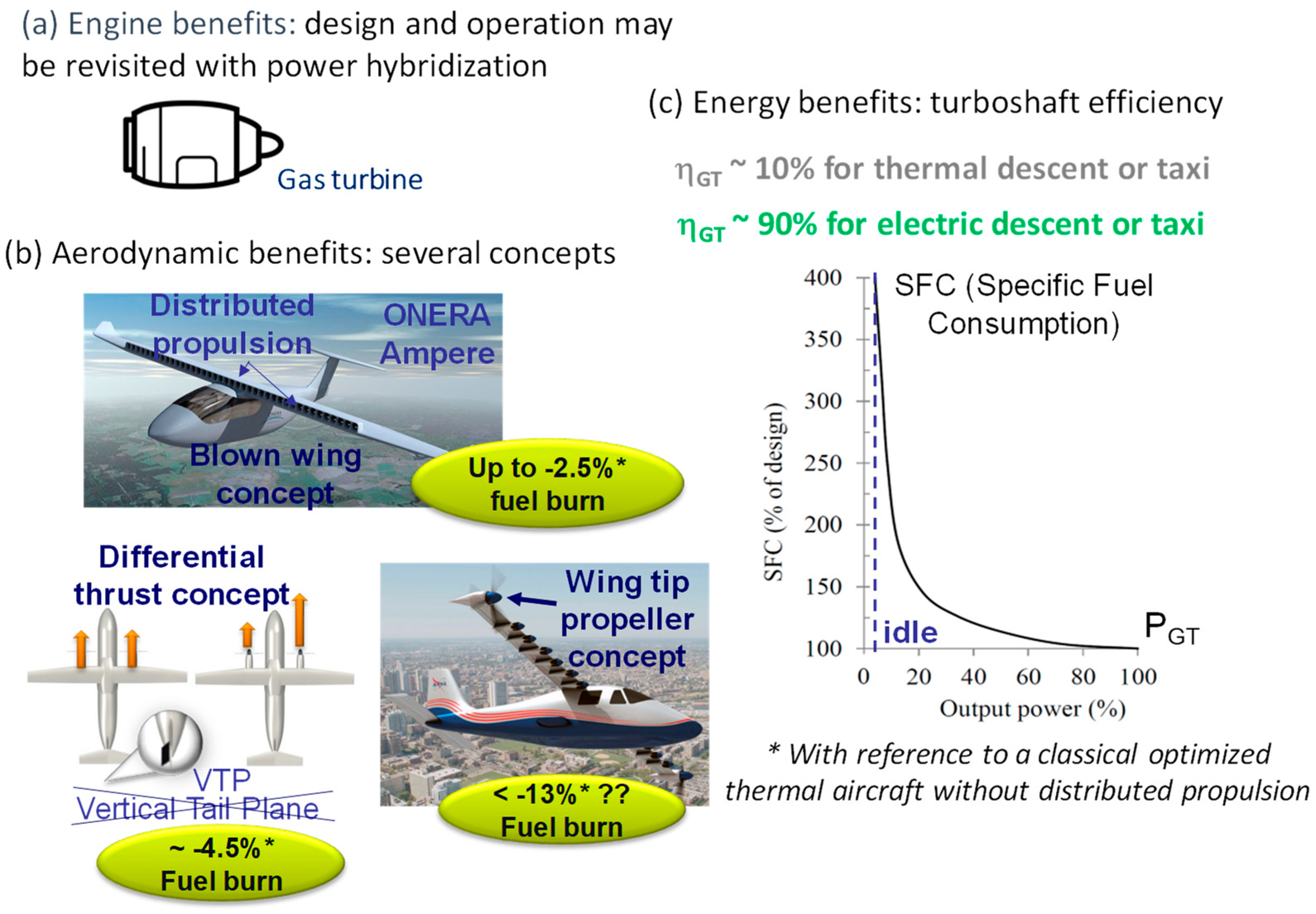
The first benefit is related to the thermal engine design, as illustrated in Figure 7a, due to the degrees of freedom offered by the hybrid architectures. Indeed, the electric power boost capability can be useful in particular operation zones; it allows for optimizing the engine design with respect to conventional propulsion, where the gas turbine alone propels the aircraft.
-
Secondly, Figure 7 illustrates the aerodynamic benefits, which are studied in many projects but are not detailed in the examples of Section 3 and Section 4. However, distributed propulsion introduces, in the first place, potential gains allowing a reduction in wing surface (thus decreasing drag in flight) via the concept of “blown wing”, as proposed, for example, by NASA [11] and ONERA [12,13]. This concept consists, during the landing phase, of increasing the lift thanks to the blast effect caused by the distributed electric propellers. The high dynamics of electrically powered propellers also suggest the possibility of eliminating or reducing the rear vertical plane (reduction in weight and drag) via the concept of “differential thrust” [10]. Finally, some studies suggest that vortex effects can be reduced by adding propellers at the wingtips, for example, in the X57 concept [11]. Overall, coupling all aerodynamic benefits, Thauvin [10] estimates a net reduction of 15–20% in fuel consumption for a regional aircraft.
-
Finally, energy benefits due to hybrid-electric-powertrain optimization will be especially detailed in the example of Section 3. The example of Section 4 presents a typical hybrid architecture that mainly suppresses power electronics, thus obtaining energy gains by reducing the powertrain weight. These “energy gains” are the result of the trade-off between weight reduction and powertrain efficiency including the gas turbine operation over the flight mission. Indeed, increasing the efficiency of each conversion stage implies a reduced energy demand of the upstream stages in the propulsion chain, offering subsequent weight gains. Moreover, in the case of hybrid systems combining a main thermal source, typically a gas turbine, and auxiliary electrical sources (batteries or fuel cells), it is possible to reduce the fuel burn through a power management optimization of both sources to avoid operating the thermal engines in very-high-consuming regimes obtained at low power operation, as displayed in Figure 7c. Specific flight sequences such as taxiing or descent can thus be advantageously “electrified”.
The advantages of energy hybridization between a main thermal source and an auxiliary electric source are well known in terrestrial transports, especially in electrified cars, but also in railway and marine transportation. However, this depends heavily on the characteristics of the driving mission; “an aircraft does not recover energy during braking or descent”, unlike electric vehicles. Moreover, the intermittence of mission cycles is favourable for hybridization. However, aircraft missions are mainly continuous and energy-consuming. Figure 8 illustrates two indicators of “hybridability” which were introduced in [54]: the PHP (“Power Hybridization Potential”) indicates the difficulty of hybridizing a mission in terms of power, while the EHP (“Energy Hybridization Potential”) indicates the difficulty in terms of energy needs. The latter can be seen as a frequency for hybridization:
P H P = 1 P a v e r a g e P m a x ;   E H P = P m a x E u   s t o r e d   e n e r g y
where Paverage and Pmax are, respectively, the average and maximum powers over the whole driving mission, Eu being the “useful energy” that must be stored to be provided by the secondary electrical source (storage device).
In the lower part of Figure 8, two different missions in terms of power intermittence but with the same PHP are compared. “Mission 1” is clearly more difficult to face (with an increased storage size) than “Mission 2”, which is emphasized by a higher EHP in the second mission.
Table 1 draws a comparison in terms of the “difficulty of hybridizing the driving mission” (PHP, EHP) of the driving missions detailed in [10]. The comparison is between the automotive, railway, maritime, and aeronautical domains; for the latter, the case of a regional aircraft on a 200-nautical-mile (nm) route is considered.
This comparative analysis confirms that “the aircraft hybridization is not in a straight line”, the flight mission being too “heavy” to be hybridized and a priori costly in terms of the energy stored inside the electric auxiliary source (battery or hydrogen fuel cell); the EHP indicator is clearly the lowest with respect to other transport modes. It is even more necessary to combine several hybridization benefits for gathering energy gains, but also for both engine optimization and aerodynamics, in order to supplant conventional all-thermal aircraft whose efficiency has been optimized (e.g., the Airbus NEO propulsion systems consume less than 3 L per passenger per 100 km) and for which SAFs (sustainable aviation fuels) open up advantageous paths from an environmental point of view, even if their capacities remain limited.

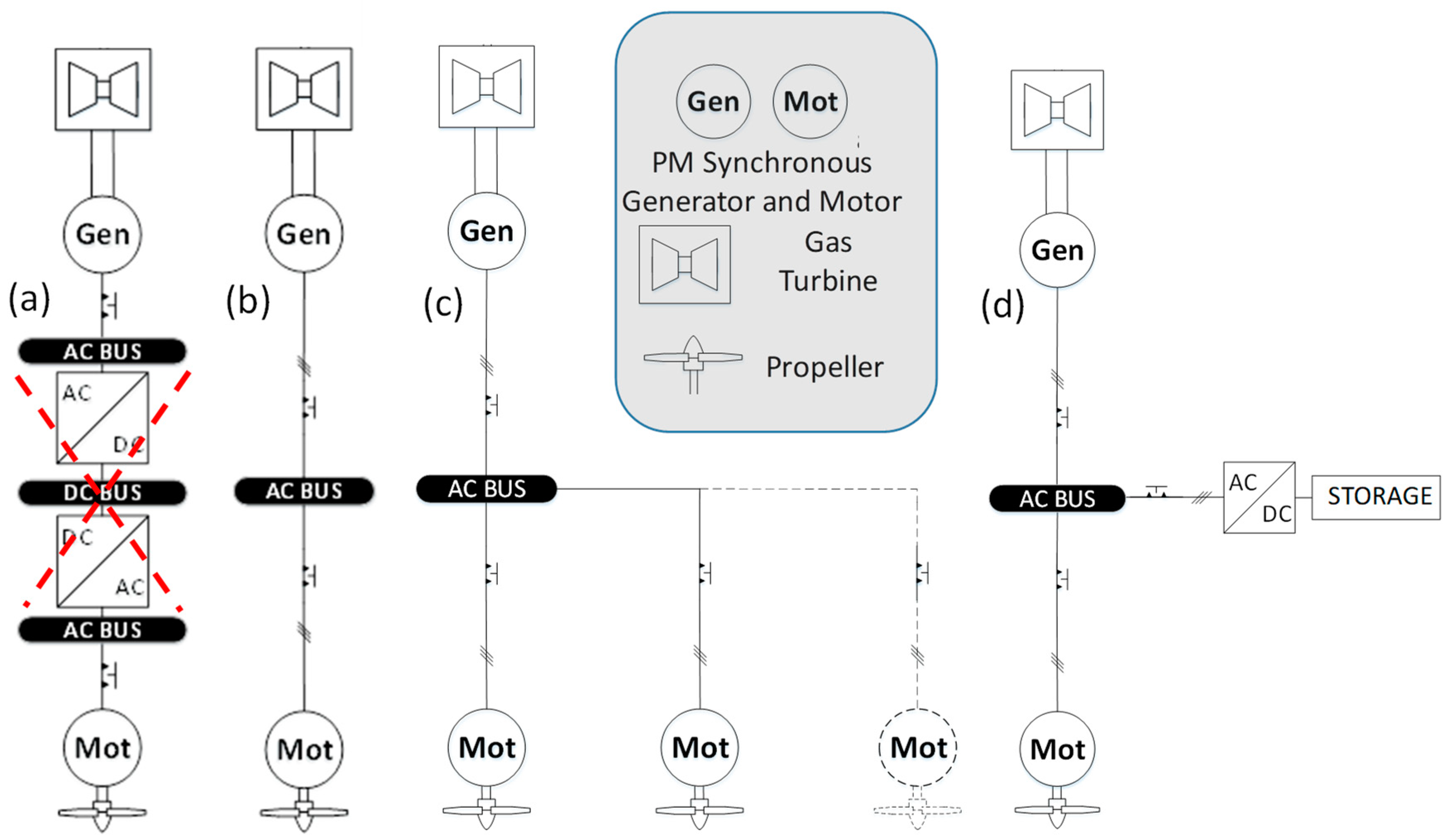
2.2. Hybrid-Electric and Full-Electric Architectures

As with electric and hybrid vehicles on the ground, there is a fairly wide variety of architectures for aircraft electrification, from “all-electric” to “series”, “parallel”, or “series/parallel” hybrid, as illustrated in Figure 9. The current projects can be classified among these architectures according to their hybridization ratio (HP, HE), as defined in Figure 10. The series architecture presented in the following section was chosen by Airbus in the context of the European Clean Sky 2/HASTECS project. Indeed, as the propelling power is fully electrified (HP = 100%), this architecture involves the most ambitious technological breakthrough. In contrast, the parallel hybrid architecture appears to be a “more prudent intermediate path”, as shown in the study carried out in [10].
-
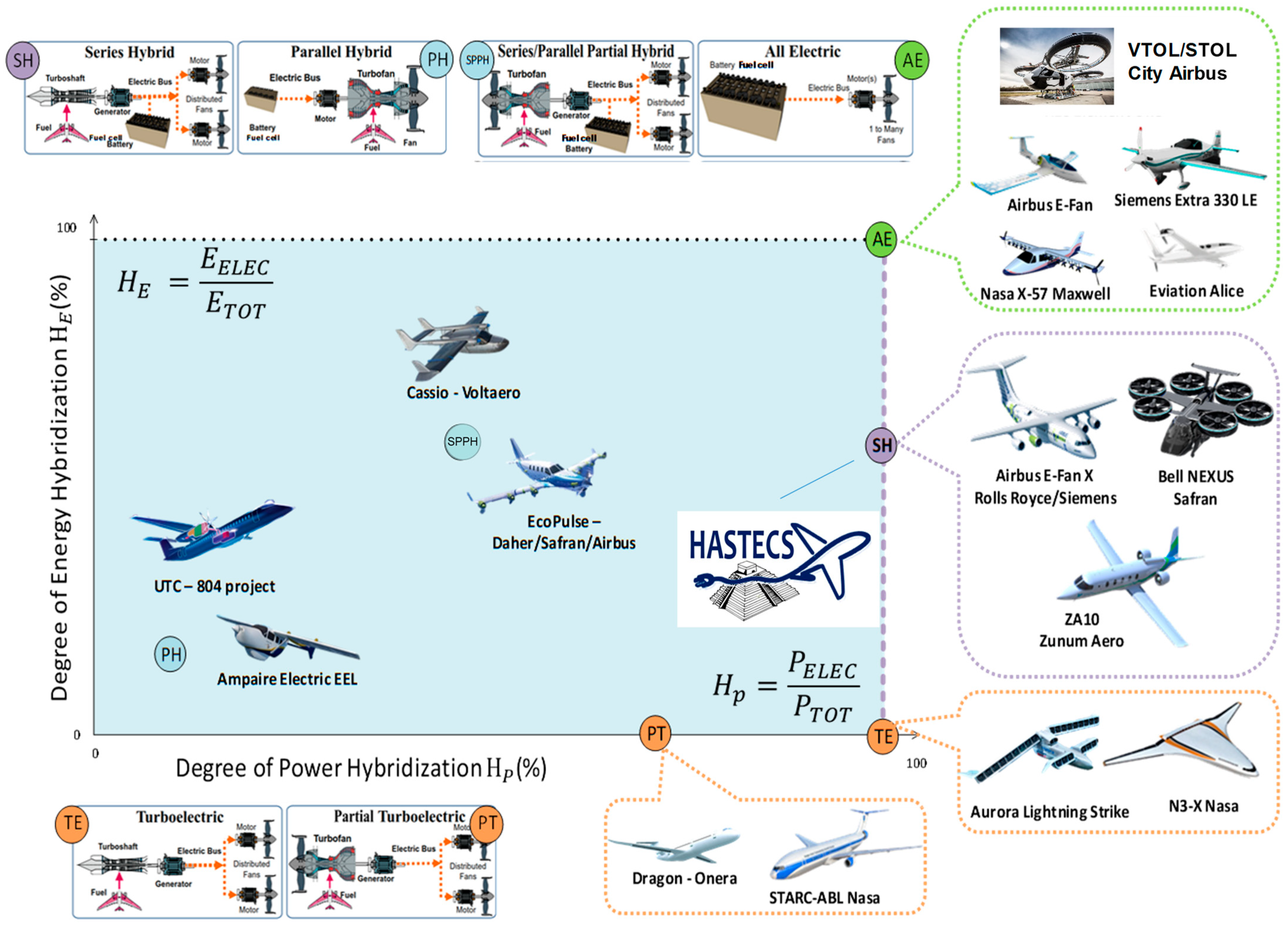
Parallel hybrid architecture: In this structure, the conventional thermal engine is assisted by the eMotor during high-fuel-consumption-demand phases (low propulsive power demand), exactly as in an electric car. The weight addition due to the powertrain electrification is minimized compared to that of other hybrid architectures, and it was found in [10] to be the most promising in terms of fuel burn reduction rate. For example, the AMPAIRE start-up [55] built a prototype of a hybrid-electric parallel aircraft, which ran until its fly tests in California in 2019.
-
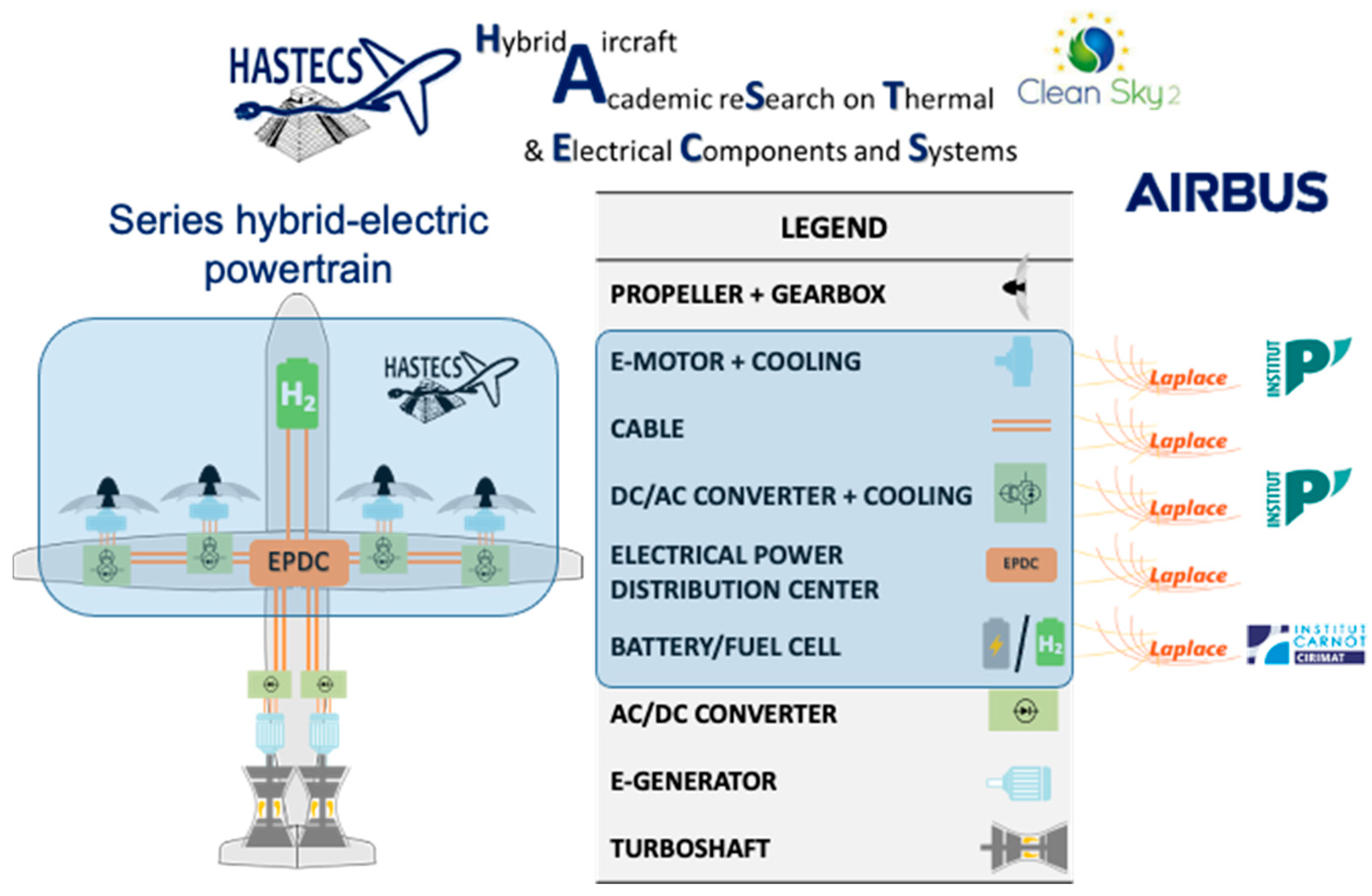
Series hybrid architecture: With 100% electric propulsion, like “Turboelectric” and “All Electric” solutions, this structure is highly compelling and involves the most ambitious technological breakthroughs, involving high-power devices (cables, electric machines, power electronics) and “ultra HVDC bus voltage standards” with subsequent issues in terms of insulation (partial discharges) in aircraft environments, especially at low pressures. This is a reason why Airbus, as the topic leader in the EU Clean Sky 2 “HASTECS” project, has chosen to retain this architecture for a regional aircraft case study; this example is detailed in Section 3. Many other projects have made the same choice, starting with the American start-up Zunum Aero [56], supported by Boeing, that develops a family of series hybrid-electric small regional aircraft, the first being the ZA10 which is able to transport 10 Pax flying over a range of 600 nm. The aircraft concept uses either all-electric or hybrid-electric modes to extend the flight range. In cooperation with SAFRAN, which has provided a 500 kW gas turbine collected from an existing helicopter, the powertrain concept can switch either to an all-electric or a hybrid-electric powertrain to extend the aircraft mission. The series hybrid-electric propulsion can also be applied to VTOL and STOL (vertical and short take-off and landing aircraft) as for the Bell NEXUS [57]. Here, hybridization is necessary to extend the fight range.
-
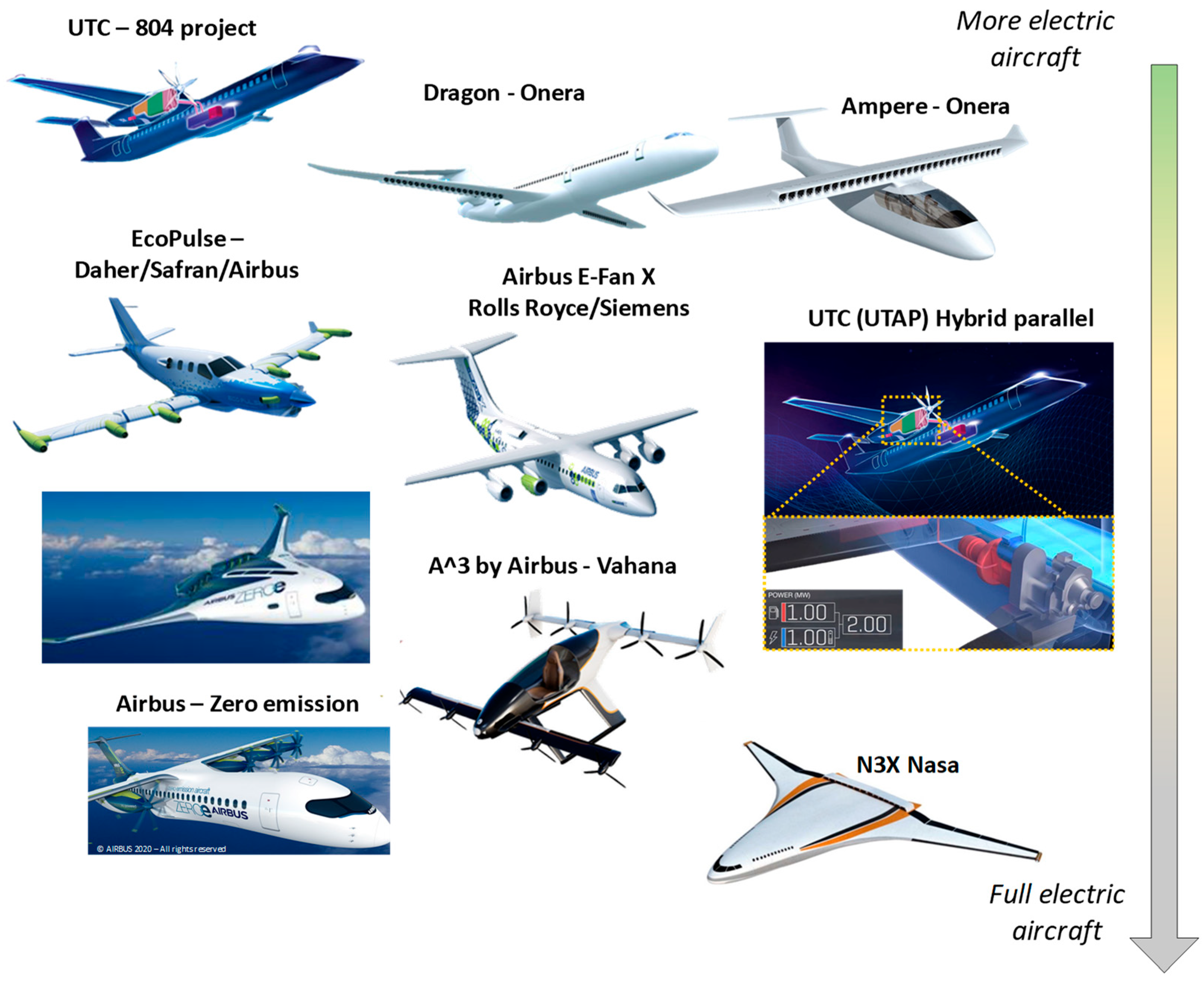
The “SPPH” (series-parallel partial-hybrid) powertrain is an intermediate concept between series and parallel hybrid architectures. A turboshaft engine partly powers a generator that feeds electric motors driving propellers, which distribute thrust along the wings. The latter is associated with storage batteries. The aircraft thrust is generated both by electric and thermal engines; the French start-up “Cassio”, with Voltaero, and the “Ecopulse” project, comprising Daher, Safran, and Airbus, are among this family of concepts.
-
All-electric and zero-emission architecture: Flying all-electric powertrain is far from easy. Several concepts and prototypes have been proposed, starting with Siemens and its “Extra 330” concept, with an aircraft speed beyond 340 km/h. It especially embeds a very high specific power electric motor [58]. Such a specific power of 5 kW/kg has never been reached for an aircraft electric motor. Beyond that, Eviation is a young company in Israel that is also studying a full-electric concept. Their aircraft, able to transport nine pax by means of its 800 kW electric propulsion and powered by lithium-ion batteries, was presented at the Paris Air Show in 2019. Alongside these new generations of aircraft, VTOL and STOL aircraft are also in the “all-electric race”. Airbus has also proposed its “City Airbus”, a four-seat multi-copter concept. The market for VTOL and STOL aircraft is rapidly growing; aircraft manufacturers want to relieve road traffic congestion and make it more fluid. However, considering the limitations of battery-specific energy for current and medium-term solutions, the range of all-electric aircraft is still very limited. Thauvin [10] studied technology targets by assessing the required battery-specific energy to get an aircraft off the ground and have it fly over a certain range depending on its maximum take-off weight (MTOW) and its performance-level assessment. The technological assessment related to these entry-into-service (EIS) targets is summarized in Table 2. In Figure 11, based on the example of a 30-ton (t) MTOW (blue curves), a 100 nm (nautical miles) full-electric flight appears to be achievable with the battery technology prediction of “EIS2025” (EIS in 2025 with 280 Wh/kg for battery-specific energy target), while, in the longer term, the battery technology of “EIS2030+” (EIS beyond 2030 with 380 Wh/kg for battery-specific energy target) would enable the all-electric aircraft to fly nearly 200 nm, which is still strongly limited.
In this context, solutions with fuel cells or hydrogen ICEs become relevant options for sustainable aircraft: Airbus actually promotes the “ZeroE” concept with the ambition of releasing hydrogen demonstrators by 2026. In the next section, we propose a synthesis of a trade-off assessed in the framework of HASTECS comparing the best-performing batteries and fuel cells with liquid hydrogen storage. Whereas the aim is to maximize the specific energy (kWh/kg), it appears that a range extension (energy demand increase) is consistent when switching towards hydrogen solutions. ZeroAvia is an American start-up that has planned to fly a hydrogen-powered 6–20 pax plane with a range of up to 500 miles. Several regional flight tests are currently being operated. The French start-up “Beyond Aero” is also heading in the same direction. In 2020, the European Union (EU) announced its Clean Hydrogen Plan [59]: in the context of the post-COVID-19 situation, the European Union is first and foremost investing in hydrogen technologies. We will come back to that promising topic in the conclusion and prospects of this review.

2.3. Electrified Powertrain Is Heavier Than Conventional Thermal Ones But “Technology Sensitive”

As introduced in Section 1.1 in Figure 5, weight is crucial in aeronautics due to the “snowball effect”. However, generally, replacing conventional thermal propulsion with an electrified powertrain leads to enhancing the embedded weight. Indeed, as illustrated in Figure 12, a hybrid-electric powertrain involves not only thermal engines with gas turbines and a propelling device but also energy-conversion devices with power electronics, generators, electric motors, cables, bus bars, etc., and the hybridization branch with electrical auxiliary sources (batteries or fuel cells). In the end, due to the snowball effect, weight added onto individual devices increases the aircraft’s MTOW, thus reducing the potential benefits of electrification.
In [41], we analysed the sensitivity of technological performance on the global weight (MTOW) and on the fuel burn in a case study of a hybrid-electric regional aircraft whose characteristics are identical to the ones detailed in the next section. In Table 3, several levels of technological targets on efficiency and specific power–energy are assessed for power electronics, electric machines (eMotor and eGenerator), and an auxiliary electric source (here, a fuel cell with liquid hydrogen). The “2025” and “2035 Targets” corresponding to the “HASTECS project” requirements and another “more aggressive” target (“20xx Target”) have been added to forecast the longer term. The upper part of Figure 13 illustrates the weight reduction at the aircraft level (MTOW) in % with respect to the “2025 target” assessments set in Table 3. The weight reduction effect is firstly shown device by device due to the electric machine performance (left part of Figure 13) and the power electronics performance (middle part of Figure 13). Then, the weight reduction sensitivity is displayed at the powertrain level by coupling all-electric components (as illustrated in the right part of Figure 13). The same analysis is proposed for the fuel burn sensitivity in the lower part of Figure 13.
This sensitivity analysis in Figure 13 emphasizes a key issue: “even if the electric powertrain is a priori heavier than thermal one, the performance of electric technologies (efficiency and specific power and energy) strongly influences both MTOW and fuel burn”. Regarding the reference “2025 Target” and crossing towards the “20XX Target” would reduce the MTOW of a regional hybrid-electric aircraft by more than 12% (emphasized by the grey bar in the upper part of Figure 13) and reduce its fuel burn by 17% (illustrated by the grey bar in the lower part of Figure 13), which is more than significant. This device-by-device sensitivity analysis also shows that the electric machine (motor and generator) is the most influential element in the whole powertrain system.

2.4. Literature Review on “Power Electronic-Less”-Electric and Hybrid-Electric Architectures

As introduced in Section 1.2, power electronics offer degrees of freedom that allow for controlling power sources and propulsion devices coupled through a DC bus. These solutions are integrated into most of the “more electric aircraft” architectures.
However, as illustrated in Figure 12, power electronics are responsible for a consequent share of weight embedded in electric powertrains. One alternative solution may be to suppress power electronic stages directly coupling electric machines (generator and motors) through an AC bus in order to lower the weight cost. Several electric machines may be used inside such “power electronic-less” architectures. For example, NASA studied [60,61] an AC electric power chain with a distributed propulsion where the electrical machines are doubly fed induction machines with power electronics placed on the rotor side. Collins Aerospace has patented [62] another solution applied to the BLI (boundary layer ingestion, introduced in Section 1.1) application concept consisting of a turbofan driving a synchronous or asynchronous generator connected via an AC bus to an asynchronous motor driving a propeller. This AC bus is also associated with a DC source connected in parallel to the AC bus, which can have hybridization and/or start-up assistance functions for the gas turbine.
However, coupling electric machines (generators and motors) with power electronics allows us to control the transient operation of the propulsive system. Contrarily, stability is at stake in “power electronic-less” architectures, as detailed in Section 4. Currently, this aspect constitutes an emerging topic in the state of the art, mainly composed of several patents proposed by actors in the industrial sector (Collins Aerospace [62], Rolls-Royce [63,64,65], Siemens [66], and Safran [67]). However, these patent propositions are mainly concentrated on architecture issues. Indeed, both the static and dynamic operation of AC powertrains are rarely studied. In Section 4, this issue is clearly addressed in the case of the direct association of PMSMs (permanent-magnet synchronous machines) through an AC bus. These electric machines are often used in embedded applications due to their maximum capacity in terms of specific torque and power. Section 4 thus proposes, firstly, a stability analysis of a power channel with direct AC bus coupling of PM synchronous generators and motors showing that oscillations may appear in certain circumstances. In order to ensure a stable operation of such powertrain architectures, regardless of the operating point, a solution consists of adding a battery-based hybridization branch with its control.

3. “HASTECS”, a Series Hybrid-Electric Powertrain for Regional Aircraft: From Technological Optimization to the MDO of the Whole Powertrain

While the models used in the previous sensitivity analysis (presented in Section 2.3) and those usually used for the MDO of electrified aircraft are very macroscopic, mainly based on assumptions regarding specific power (SP in kW/kg) and energy (SE in kWh/kg) or efficiencies (η%), this section approaches the “technological design and optimization” of the power conversion chain elements of a hybrid-electric powertrain. Furthermore, regarding the potential benefits in terms of engine optimization, aerodynamics, and energy efficiency introduced in Section 2.1, here, we only address the “energy” point of view.

3.1. The HASTECS Project

In the framework of the EU program Clean Sky 2, targeting greener aircraft, the HASTECS project (Hybrid Aircraft: reSearch on Thermal and Electric Components and Systems) [52] headed by Airbus aimed to design powertrain devices for a series of hybrid-electric regional aircraft (70 pax, 600 nm, with a global propulsive power beyond 5 MW). The vision of that project was both methodological (modelling/simulation/optimization, MDO, etc.) and technological, especially coupling electrical and thermal issues involved in the technological design at a device level and in the integrated optimal design (MDO) of the whole powertrain. Six work packages involving six PhD theses and two post-doctoral studies have led to the results summarized in that section, relating to:
-
Highly integrated power electronics [48,49] and their high-performance cooling [50,51];
-
Highly integrated electric motor [44,45] and its high-performance cooling [42,43];
-
Facing environment constraints due to high power/voltage: partial discharges [46,47];
-
Prospects towards high-energy-density batteries and fuel cells [52];
-
Integrated optimal design of the powertrain [14,68].
Coordinated by Toulouse INP University, the HASTECS project has gathered the expertise of several French labs, the LAPLACE for energy conversion, the Pprime institute for thermal aspects, and the Cirimat for Lithium Ion batteries. The research involvement in the HASTECS project is illustrated in Figure 14.

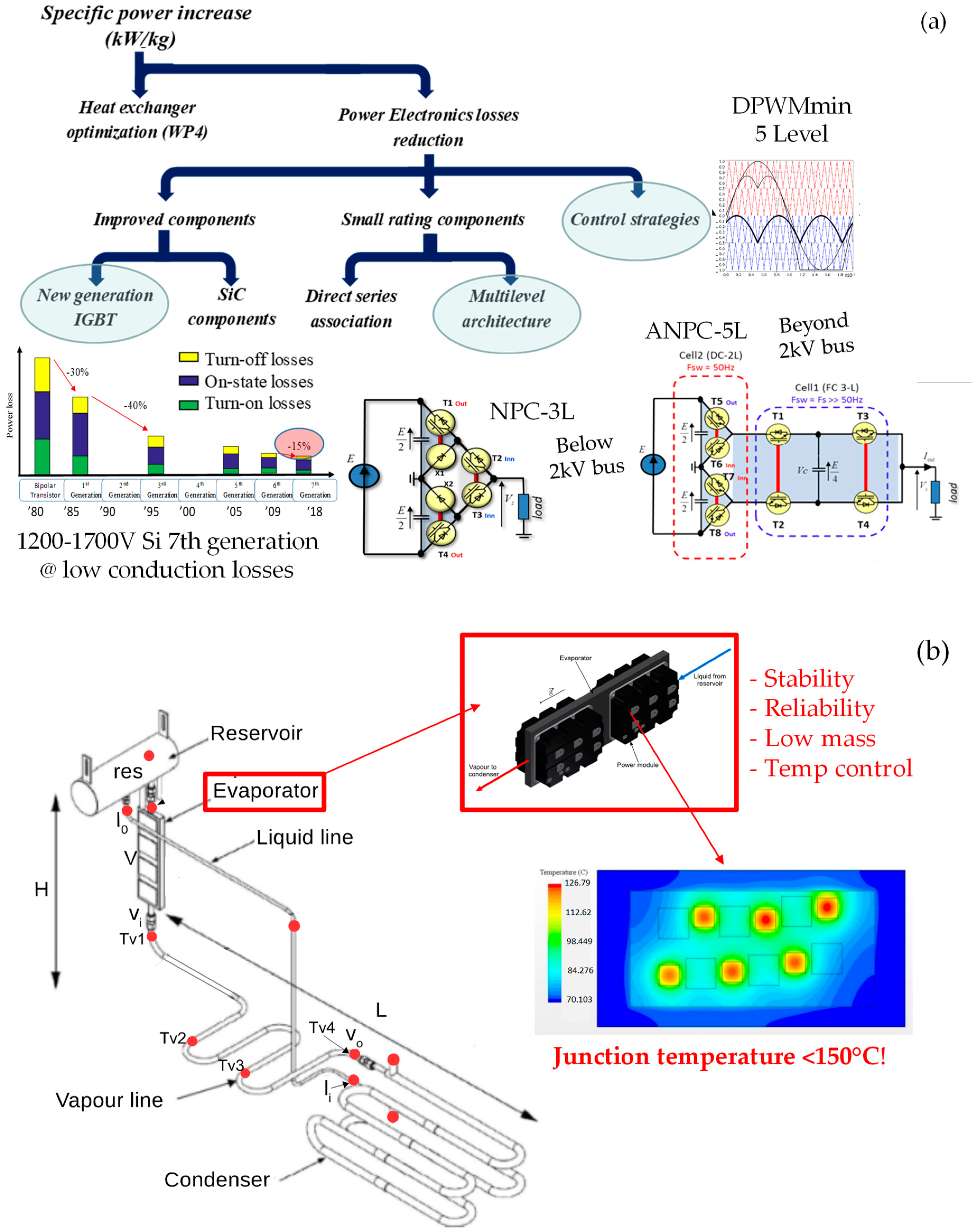
3.2. Local Optimization of Power Electronics

Several technological and structural choices have been made to increase the specific power of power electronics, as illustrated in Figure 15a, keeping efficiency at the highest standards. Readers can find more details on that topic in [48,49]. Based on the HASTECS requirements, the seventh generation of silicon IGBTs (insulated-gate bipolar transistors) are preferred over new wide-gap devices thanks to their low conduction losses leading to power inverter efficiencies of approximately 99%. Multilevel inverter structures have been selected, with a 3-level NPC (neutral point clamped) structure for an HVDC bus below 2 kV and a 5-level ANPC (active NPC) structure for those beyond 2 kV. Inside the MDO process, presented later in this section, 1200 V and 1700 V IGBTs have been rated depending on the bus voltage level. Specific PWM (pulse width modulation) strategies (“DPWMmin” strategy) with loss minimization plus bus bar optimization (taking into account partial discharge constraints) have completed the electrical design of this MW range converter.
The local optimization of this power converter has converged towards a 2 kV DC bus. This DC bus standard also deals with the system optimum (i.e., powertrain MDO), taking into account (among other system couplings) electric machine association fulfilling partial discharge constraints and cabling sizing.
However, the high integration of such a power converter with low volume and weight also involves critical thermal problems. The study detailed in [50,51] proposed a very high-performance two-phase cooling device, whose structure is depicted in Figure 15b. The capillary pumped loop for integrated power (CPLIP) cooling system allows suppressing the electric pump that is usually added to that device. The heat sources, due to power module losses, are placed face to face around the “evaporator”. The diphasic system (gaseous at the output of the evaporator and liquid at the output of the condenser) offers huge capabilities in terms of heat extraction: the power module is able to evacuate 4.5 kW of thermal losses for each kg of the whole cooling system. Coupling the power electronic design with this high-performance cooling device, the MW range power converter offers specific powers beyond 30 kW/kg.

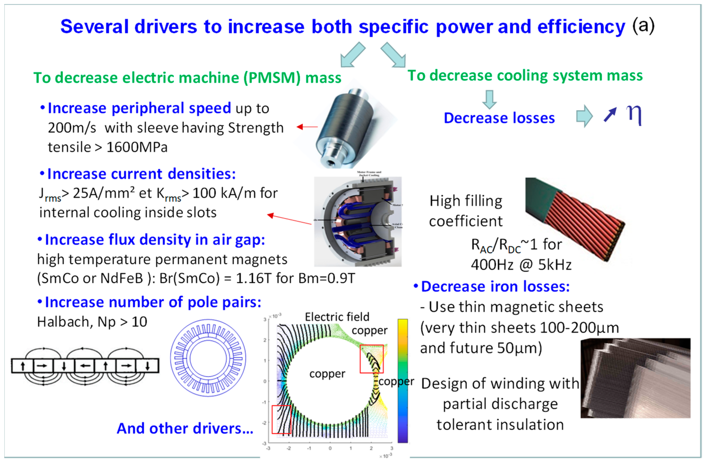
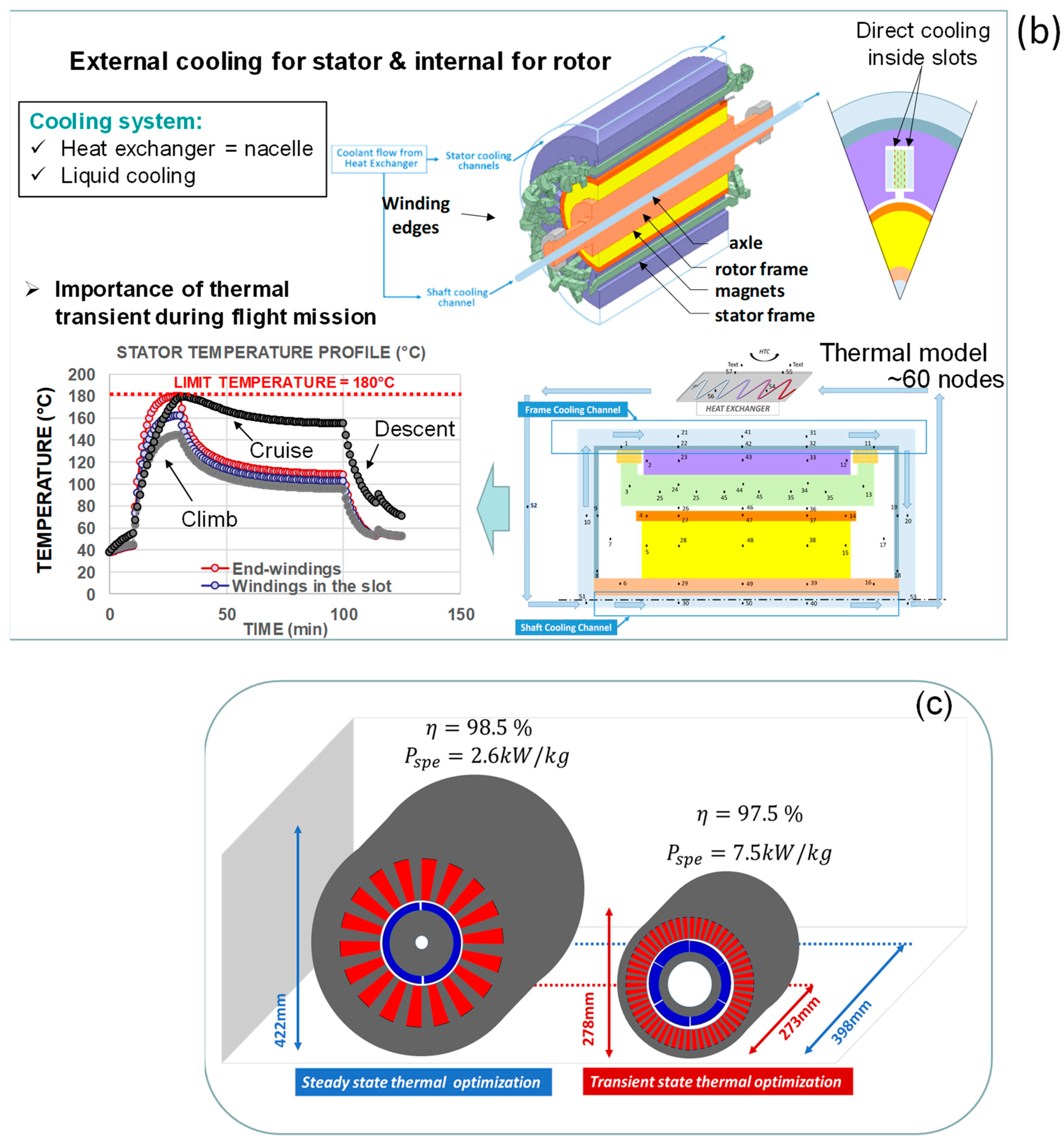
3.3. Local Optimization of the Electromechanical Actuator with Partial Discharge Tolerance

In the same way, the actuation sub-system (i.e., the eMotor for aircraft propelling) has been optimally designed [44,45] following several drivers to increase both specific power and efficiency, as illustrated in Figure 16a. The main drivers are related to this high-speed actuator (here, an SMPMSM: surface-mounted permanent-magnet synchronous machine) with limited but increased peripheral speeds and temperature-tolerant high-flux-density permanent magnets (SmCo). Specific stator windings with twisted Litz wires have been designed to limit AC joule losses at high frequencies. Ultra-thin magnetic sheets are also used to lower iron losses. Furthermore, a detailed study on partial discharge tolerance in the insulation system of the electric motor stator was achieved [46,47].
The actuation system optimization is driven by numerous design constraints, the most sensitive being the temperature limits inside the electric motor. As for power electronics, a high-performance water cooling system was studied in [42,43]. A glycol water jacket was used for the external cooling of the stator and the rotor shaft cooling. However, in order to overshoot the specific power target (10 kW/kg) set considering the HASTECS requirements for the eMotor design, an additional cooling channel directly inside the stator slots were required to face the joule losses, as illustrated in Figure 16b.
Coupling the electromechanical design with that cooling device, it has been analysed that transient states due to thermal inertia in the actuator were predominant and should be exploited during the flight mission. As illustrated in the stator temperature profile in Figure 16b, thermal limits are reached at the top of a climb, especially inside the stator-end windings. Thus, exploiting thermal inertia with a transient-state thermal model (see Figure 16c, right), the actuator power density is far beyond that obtained with optimization based on a quasi-static thermal model (see Figure 16c, left).
The synopsis in Figure 17a depicts local optimization based on the clearing metaheuristic [69] only minimizing the eMotor weight, also detailed in [68]. In that process, a large set of multiphysical constraints are integrated by coupling thermal limits with partial discharge tolerance and other geometrical and electromagnetic constraints. Note also that this optimization and all the ones that follow are achieved over the flight mission, fulfilling constraints for all flight sequences. In particular, the thermal limits are derived all over the flight mission.
As illustrated in Figure 17b, the left part displays the motor structure with only external cooling for both the stator and rotor, while the right part of that same figure displays the influence of water cooling directly inside stator slots, which strongly increases the specific power of this high-speed SMPMSM actuator beyond 15 kW/kg, with high efficiencies (>98%).

3.4. Prospective State of the Art and Modelling of High-Energy-Density Batteries vs. Fuel Cells

To complete both the design and modelling task in HASTECS and to progress towards the system integration of the whole powertrain, a state of the art and modelling study on auxiliary electric sources was conducted in [52], assessing the trade-off between future high-density batteries and fuel cells. This prospective study clearly showed that the energy density of fuel cells is significantly higher than that of the best lithium-ion batteries, such as NMC solid-state technologies. It is important to notice that this comment is only related to the mission typically involved in regional flights: this trade-off was based on the particular power–energy requirement defined in Figure 18: Pmax = 280 kW and Etot = 160 kWh are required for the auxiliary electric source to be controlled with a “simple EMS” (energy management system), which a priori sets the hybrid ratio (HR) defining the electric vs. full (electric + thermal) power ratio, i.e.,
* HR = 1 for full-electric operation during taxi and descent;
* HR = 0 for full-thermal operation during climb and cruise sequences.
The Wh/kg ratio of the fuel cell system was derived, considering both the fuel cell stack with its balance of plant and the H2 storage device. For the latter, cryogenic (20 °K) liquid storage was selected for the hydrogen, assessing 20% of the H2 tank weight. A specific power of 1.5 kW/kg was assessed for the fuel cell stack with its balance of plant (including the thermal management device). Based on these assessments and the mission profile in Figure 18, Table 4 shows that the specific energy of a fuel cell system, including its balance of plant and liquid cryogenic H2, offers a global specific energy which is multiplied by 1.8 the one obtained with the best-performing batteries according to prospective assessments for the next 5–10 years.

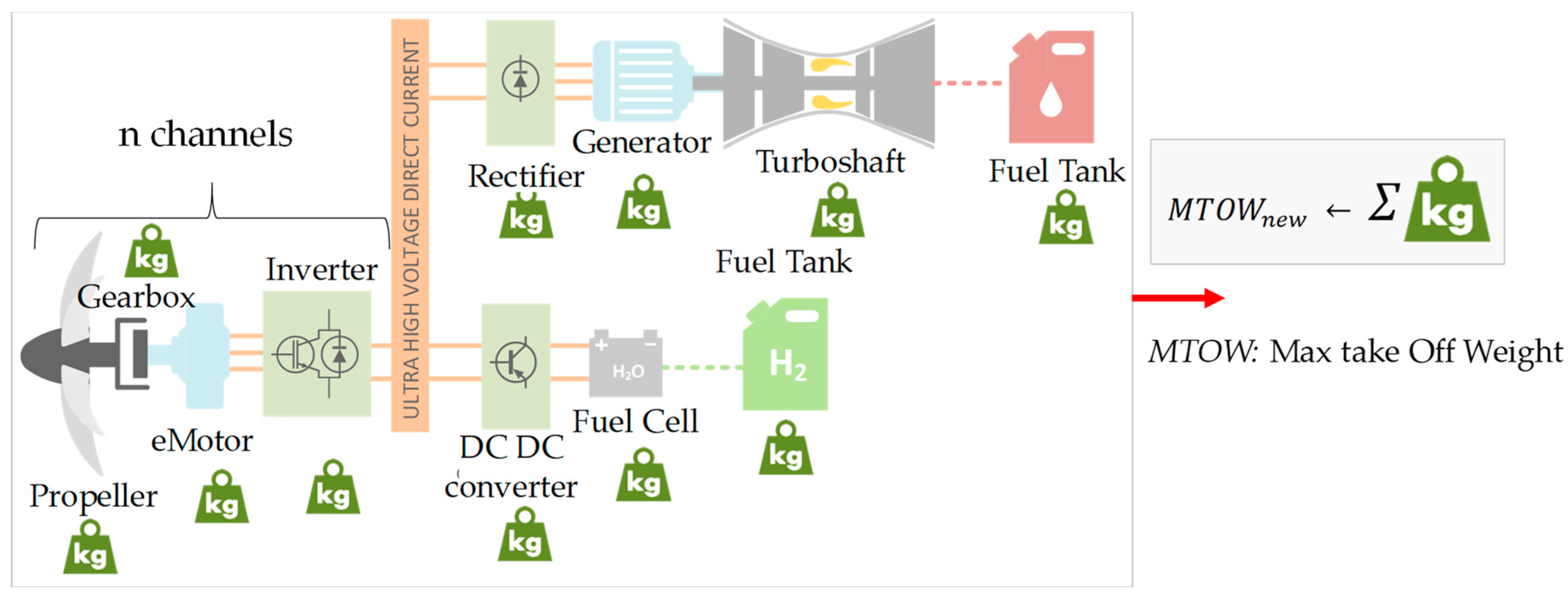
3.5. MDO of the Whole Hybrid-Electric Powertrain

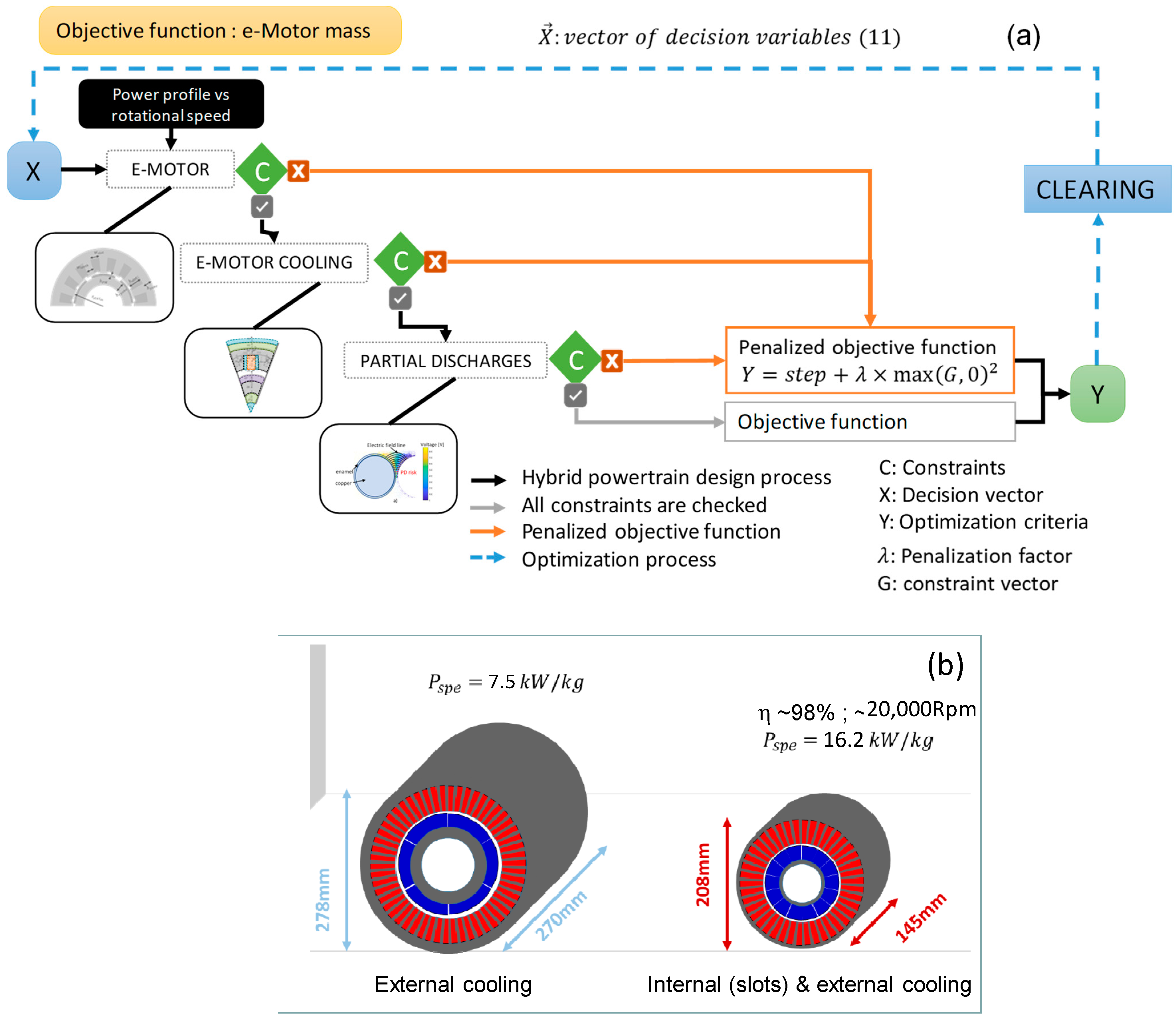
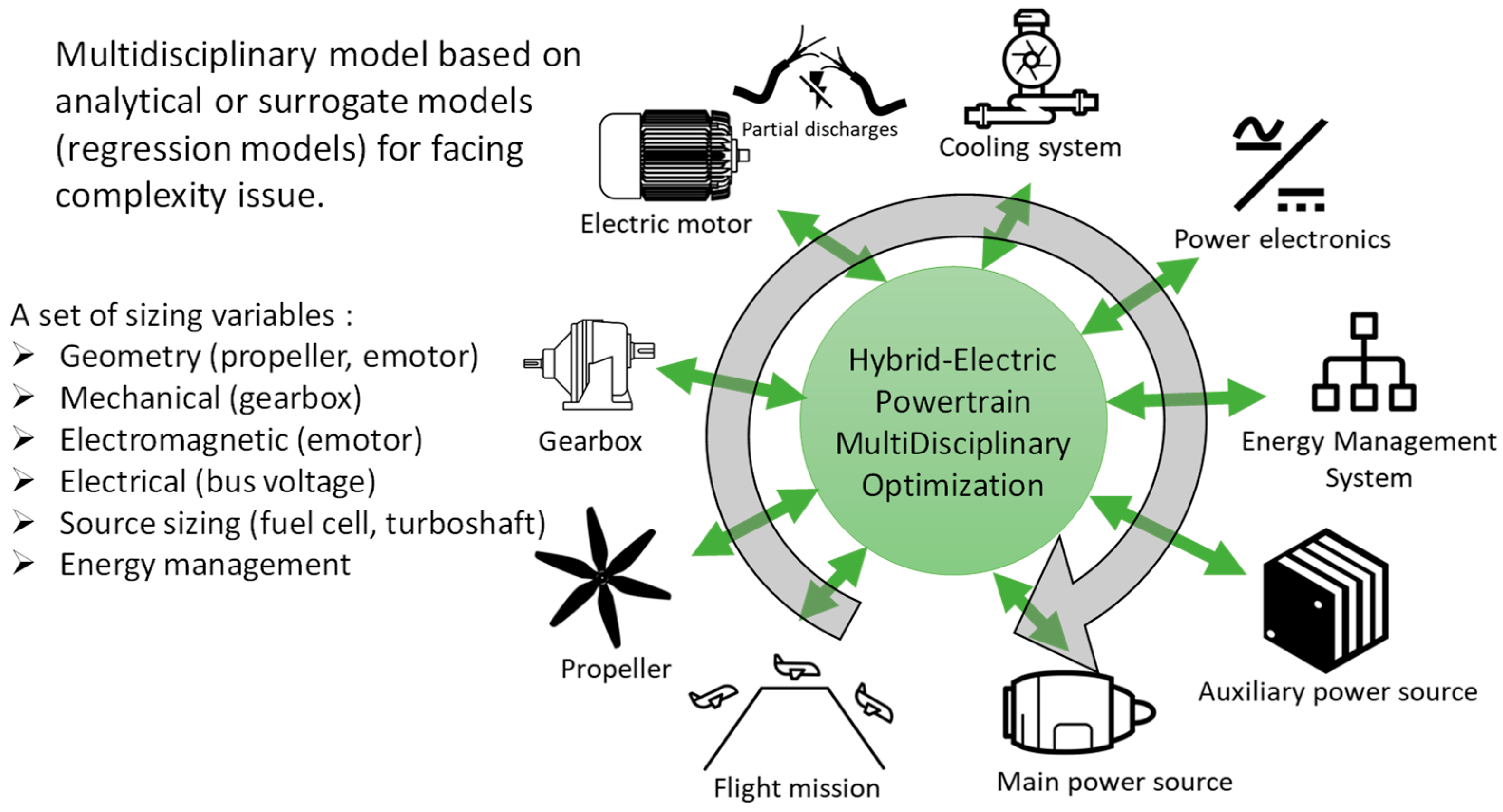
3.5.1. On the MDO Process Formulation

Beyond the design of each powertrain device studied separately, a multidisciplinary design by optimization (MDO), introduced in Section 1.1 and illustrated in Figure 6, was conducted in [14]. The MDO process integrates a large set of surrogated models, as illustrated in Figure 19, some of them directly obtained from HASTECS studies. Complementary models for gas turbines, propellers, cables, and gearboxes have been derived from the state of the art and with the help of Airbus studies [10].

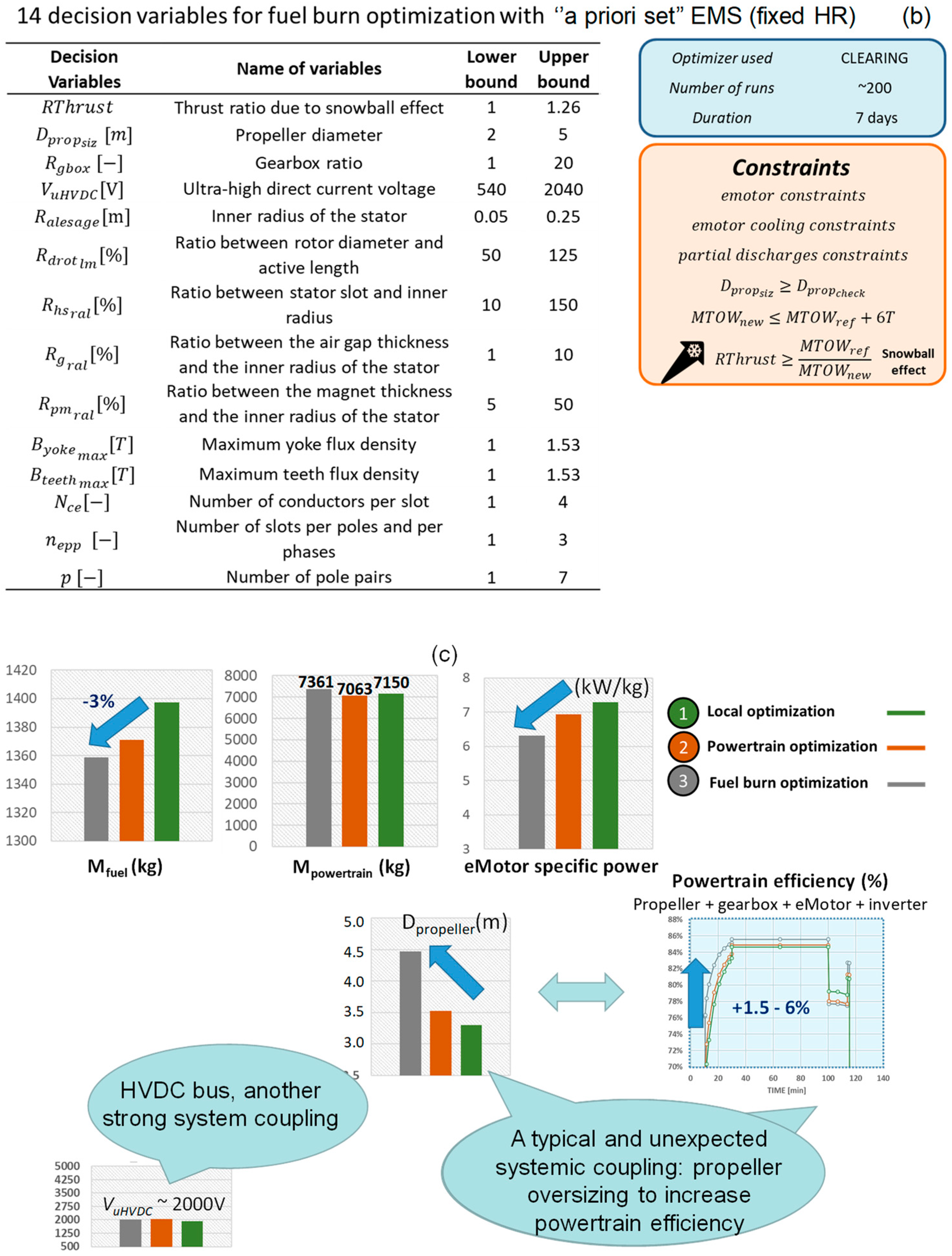
3.5.2. Optimization of the Whole Powertrain

The MDO of the whole hybrid-electric powertrain was the last objective of the HASTECS project. Readers may find much detail on device models, especially on surrogate models for optimization, in [68] for the electromechanical actuator and in [14,70] for the whole powertrain system and the MDO problem formulation. Once the powertrain models are integrated into the MDO, an implicit loop estimates the required thrust to take off the aircraft. Indeed, as illustrated in Figure 20, weight variations during the MDO convergence induce a snowball effect as the aircraft’s maximum take-off weight (MTOW) is derived from unit weights involving its subsequent thrust needs. This sizing loop may be complex when involving couplings with both structure and aerodynamics (drag penalties). In our case, as illustrated in Figure 20, the problem was linearized, simplifying the equation and assessing variations in the MTOW versus the thrust required to fly the mission:
Thrustnew = Thrustref × (MTOWnew)/(MTOWref).
This approach was validated (for a limited weight range) by comparing this linear model with more accurate models (aerodynamic models) as detailed in [10].
Three different MDO formulations are illustrated in Figure 21a. They are compared in the results below:
(1)
A “local optimization” focusing on the eMotor weight minimization: in this case, other powertrain devices are considered with fixed ratings and the snowball effect is involved;
(2)
A first global optimization minimizing the whole electric powertrain weight;
(3)
A second global optimization minimizing the fuel burn of the overall hybrid-electric aircraft.
When the “simple EMS” is coupled in the optimization process with an “a priori” set hybrid ratio (HR) as defined in Figure 18, the third formulation (i.e., fuel burn minimization with global MDO) involves the 14 decision variables displayed in Figure 21b with a large (15) and heterogeneous set of design constraints coupling electrical, electromechanical, and thermal constraints and involving the partial discharge tolerance (filling factor verification for stator windings). A supplementary constraint was integrated at the aircraft level to integrate the snowball effect.
The clearing procedure [69] was selected for optimizing the propulsion system of the hybrid aircraft. Clearing is a niching elitist genetic algorithm that usually offers better results than standard genetic algorithms, especially on multiple nonlinear constraints and multimodal problems. About 7 days of CPU time was required to solve each optimization on a standard computer.
As displayed in Figure 21c, left, the best solution in terms of kerosene consumption was logically found with the “fuel burn optimization”, which consumes 3% less than the fuel burn assessed from the “local optimization”. However, it should be noted that the “fuel burn optimization” formulation slightly increases the powertrain weight (7361 kg is obtained with reference to the 7063 kg obtained with the powertrain weight minimization). In fact, as shown in Figure 21c, the propeller diameter is increased in order to enhance the efficiency of the propeller and, consequently, the whole powertrain efficiency. Indeed, the latter is increased by 1.5% to 6% depending on the flight sequences with reference to the “fuel burn optimization”. The propeller efficiency increase (downstream in the powertrain) lowers the maximum values of the power demanded by the upstream components, consequently lowering the kerosene consumption. This clearly emerges from a “typical systemic coupling”, which emphasizes the relevance of the MDO process being able to involve the main system interactions.
In contrast, the local formulation induces, without surprise, the biggest motor-specific power. We notice that all results presented in that section were obtained without internal stator cooling inside slots. As illustrated in Figure 17b, adding internal cooling allows for quasi-doubling motor-specific power.
Finally, an optimal HVDC bus voltage range close to 2 kV was reached through the MDO process. This system trade-off was obtained thanks to coupling a wide set of domains (power electronics, eMachine, thermal cooling, and partial discharges).

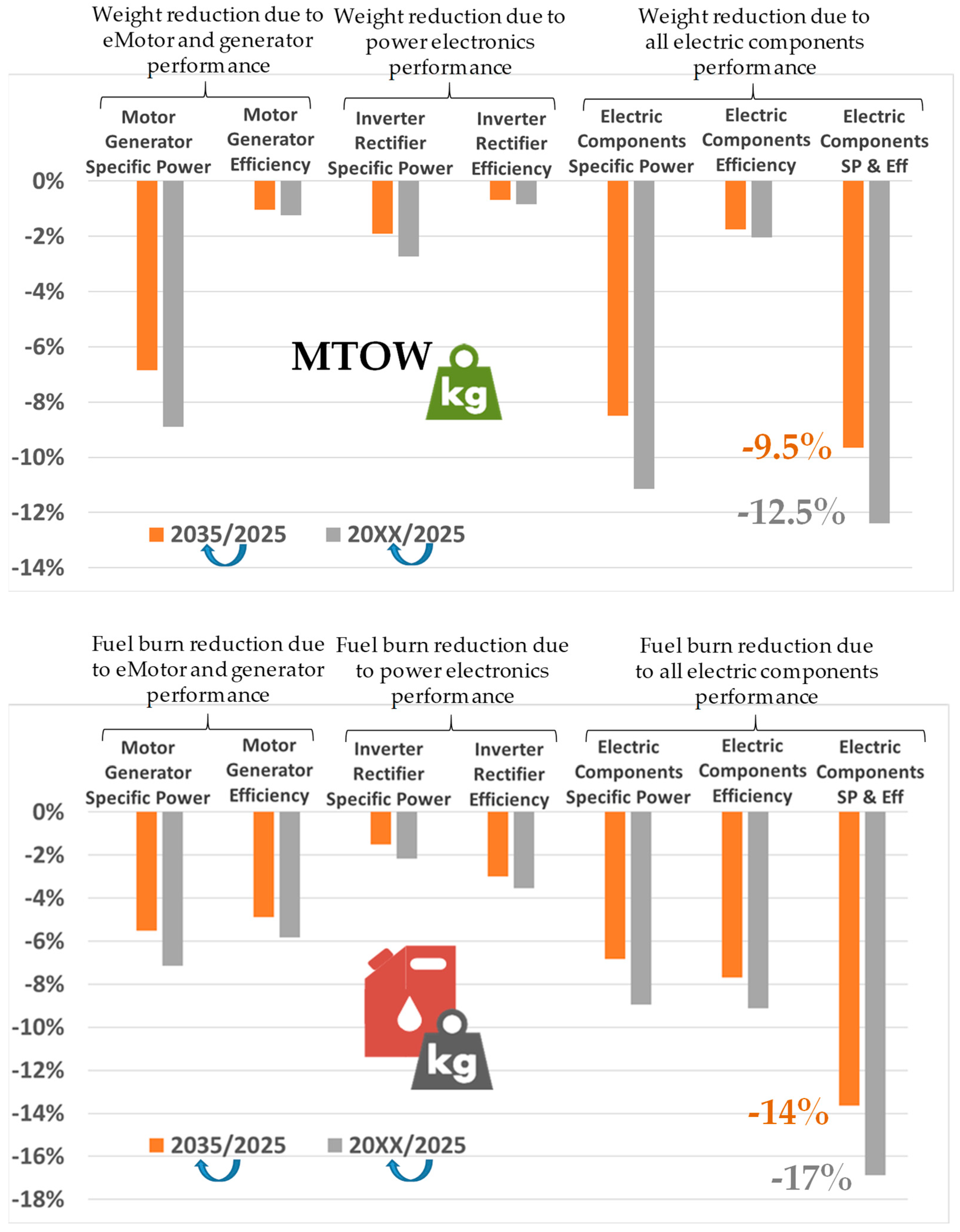
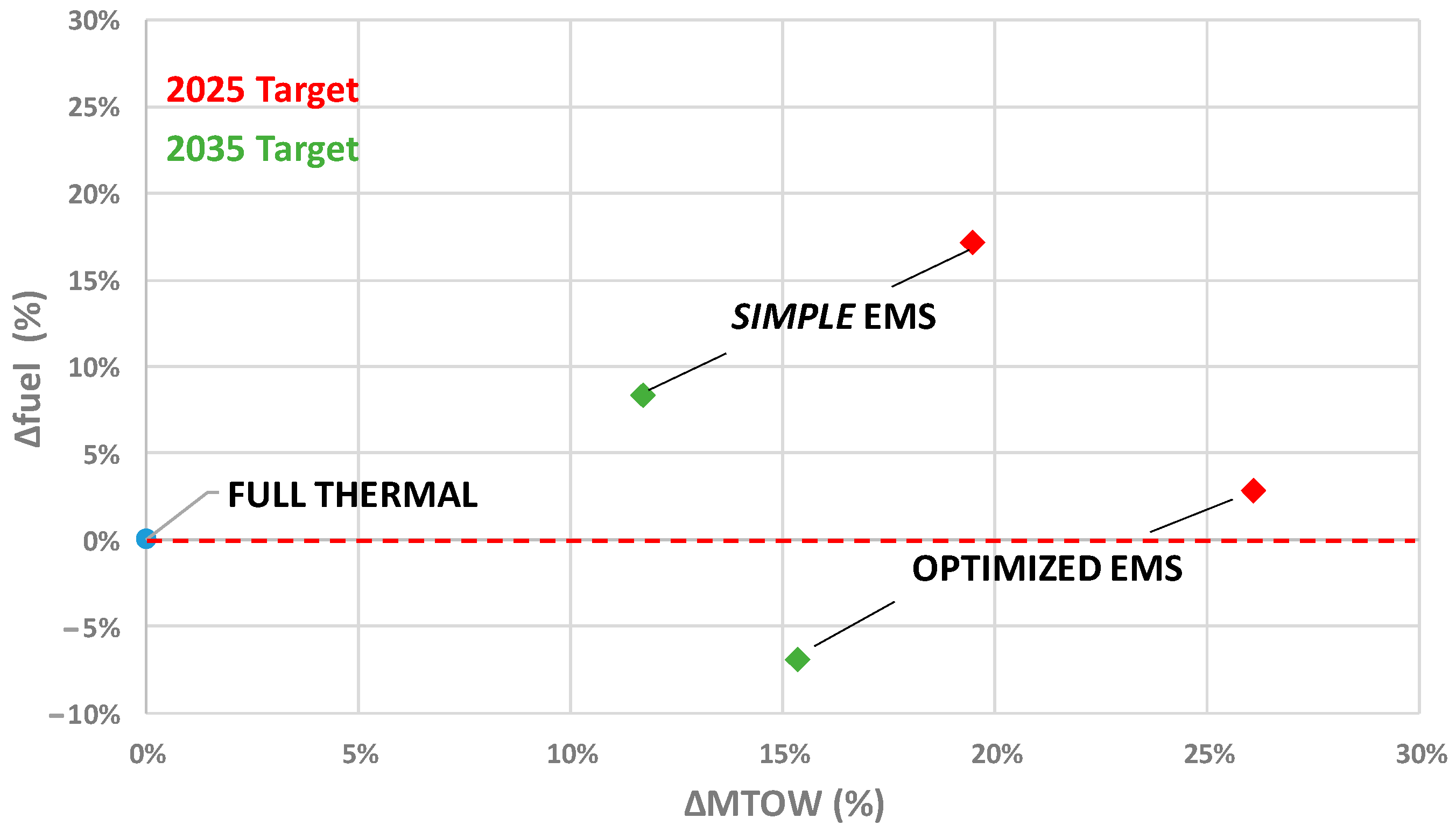
3.6. Final Trade-Off on Fuel Burn vs. Embedded Weight with Hybrid-Electric Architecture

In this section, the main results of the HASTECS Clean Sky 2 project are presented, synthesizing a set of technological optimizations at the device (power electronics, eMotor, auxiliary electric sources) level. The study has also assessed environment constraints related to the flight mission involving partial discharge tolerance, impacting especially at high altitudes and with high voltage operation.
Finally, a global trade-off was completed; results are displayed in Figure 22. This figure compares different assessments displayed in the fuel-burn-versus-MTOW plan. Two levels of targets (i.e., “2025 and 2035 targets”) were assessed. Relative variations are displayed with reference to a full-thermal aircraft optimized with the same level of model granularity. The main difference between those two targets is the cooling performance of the power electronics and electric motors: for the latter, direct cooling inside stator slots is added (“2035”) or not (“2025”). In that figure, the “simple EMS” previously presented in Figure 21a with an “a priori set” hybrid ratio (full-electric taxi and descent and full-thermal climb and cruise sequences) is compared to an “Optimized EMS” integrated inside the MDO. In that case, EMS parameters (i.e., the hybrid ratio becomes decision variables) are among the optimization variables.
This latter analysis clearly shows a major result: “despite the technological progress, electrified powertrains are heavier than thermal ones”. The “optimized EMS” which significantly increases the fuel cell nominal power leads to a significant decrease in the fuel burn, but it leads to a huge MTOW, increased by 4–7%, with respect to the previous (“simple EMS”) case.
Finally, with an “optimized EMS”, an aircraft optimized only by means of thermal technologies consumes roughly the same amount of kerosene as a hybrid-electric aircraft under the “2025 target” assumptions. Technological improvements with higher specific powers in the “2035 target” lead to a fuel burn reduction of around 6% with reference to a full-thermal optimized aircraft.
Finally, only the consequences on the fuel burn of energy efficiency and weight variations embedded in the powertrain were assessed in that subsection. As introduced in Section 2.1 and illustrated in Figure 7, going towards distributed electric propulsion architectures involves supplementary gains in terms of aerodynamics, including several innovative concepts becoming accessible such as blown wing, boundary layer ingestion, and wing tip propellers. Furthermore, hybridization with a power boost from an auxiliary electric source would allow for optimizing the thermal engine’s (primary source) design and operation.
These prospective results emphasize the key issue of the hybrid-electric concept in aviation: with reference to a full-thermal aircraft with the same level of optimization, the embedded weight is increased significantly.
The future full-electric zero-emission aircraft may constitute “the actual technological breakthrough” and has to be more deeply studied, as recently proposed by Airbus. However, engineers still have to face huge challenges in terms of technological integration and safety before talking about the certification of these innovative and greener aircraft concepts.

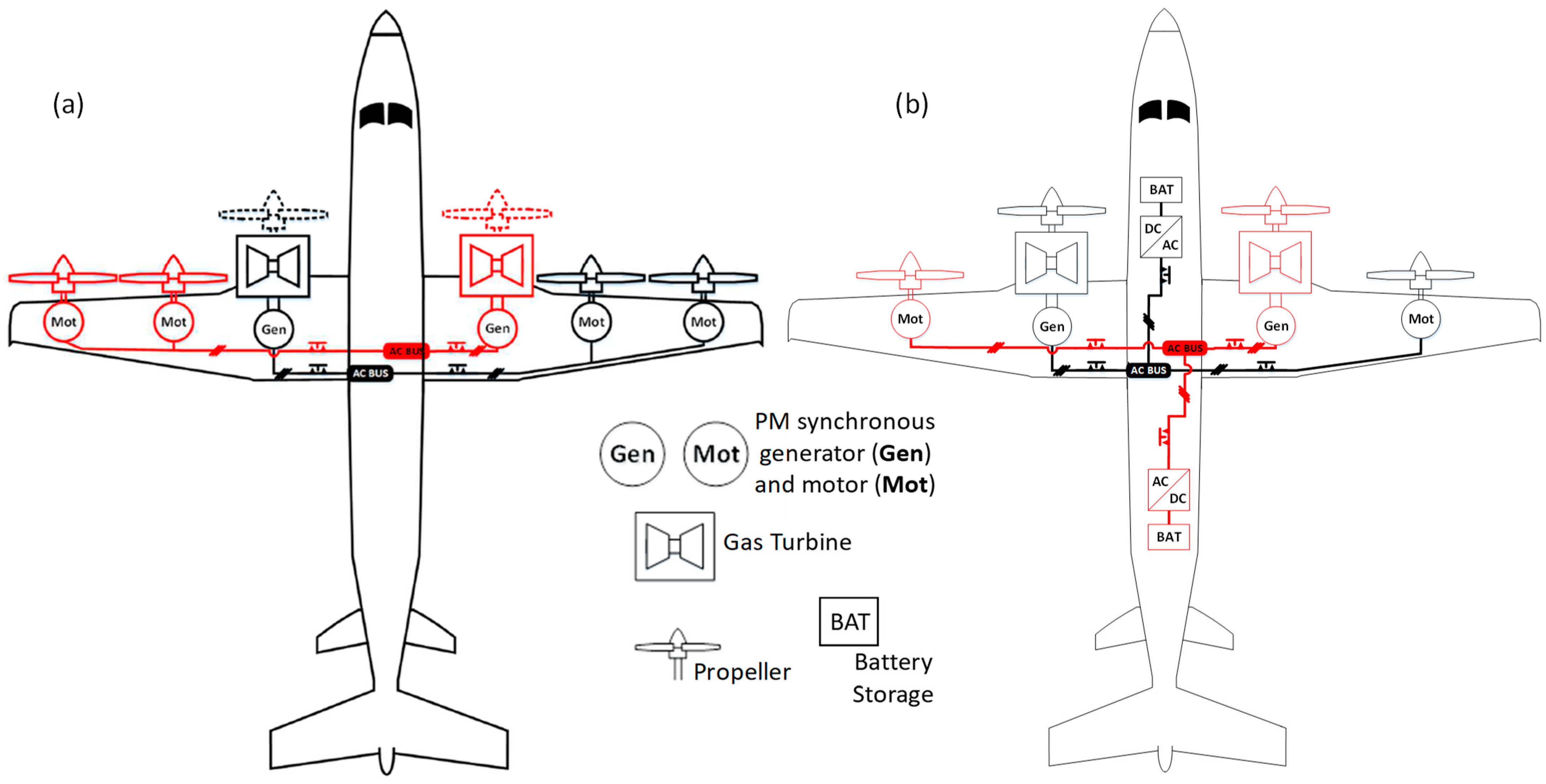
4. “Power Electronic-Less” AC Architecture Stabilized by Hybridization: Another Solution for Electric Powertrain Weight Decrease

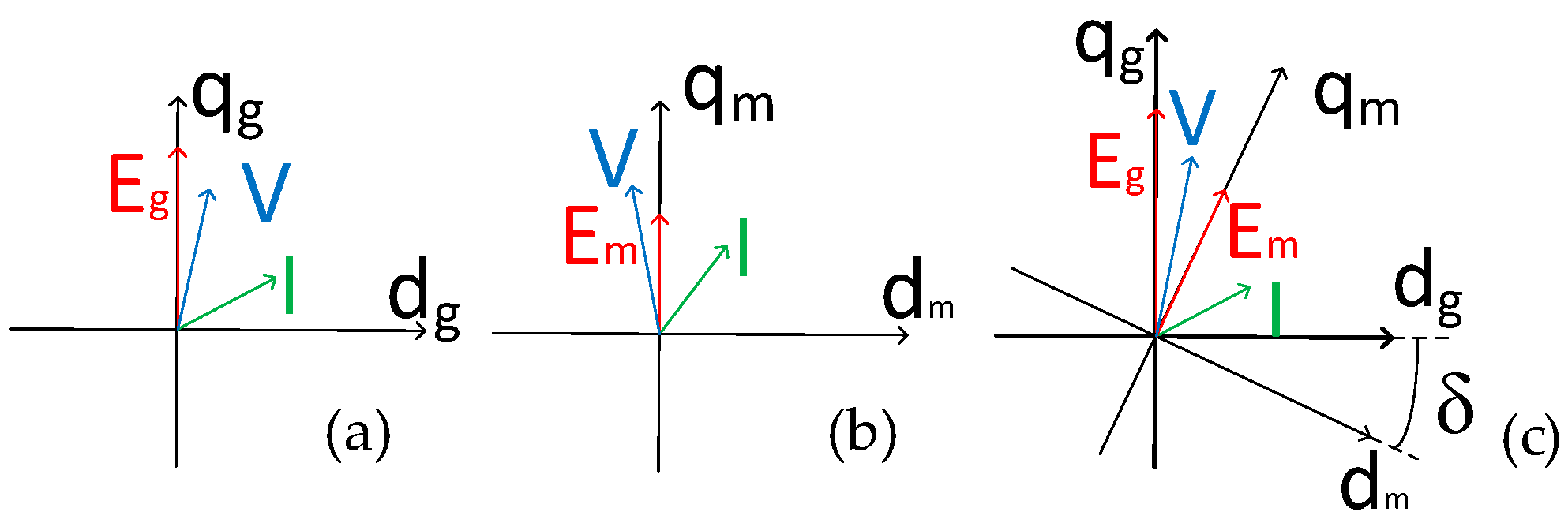
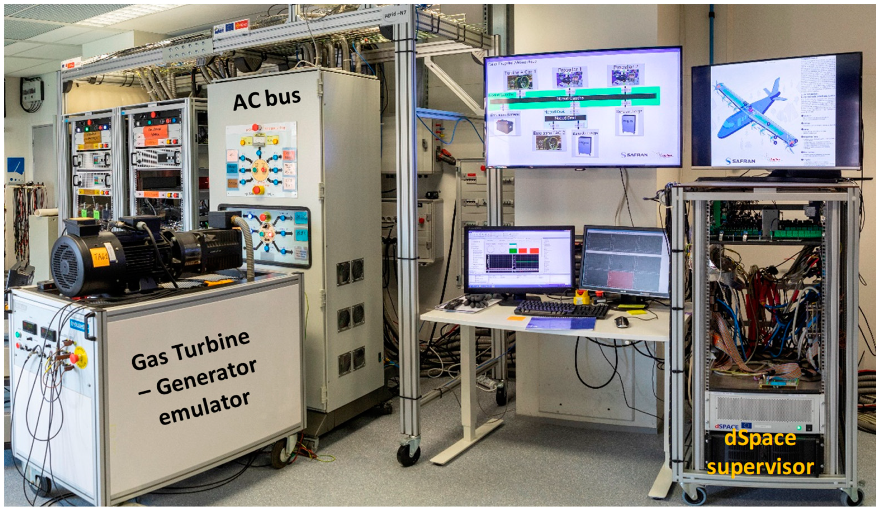
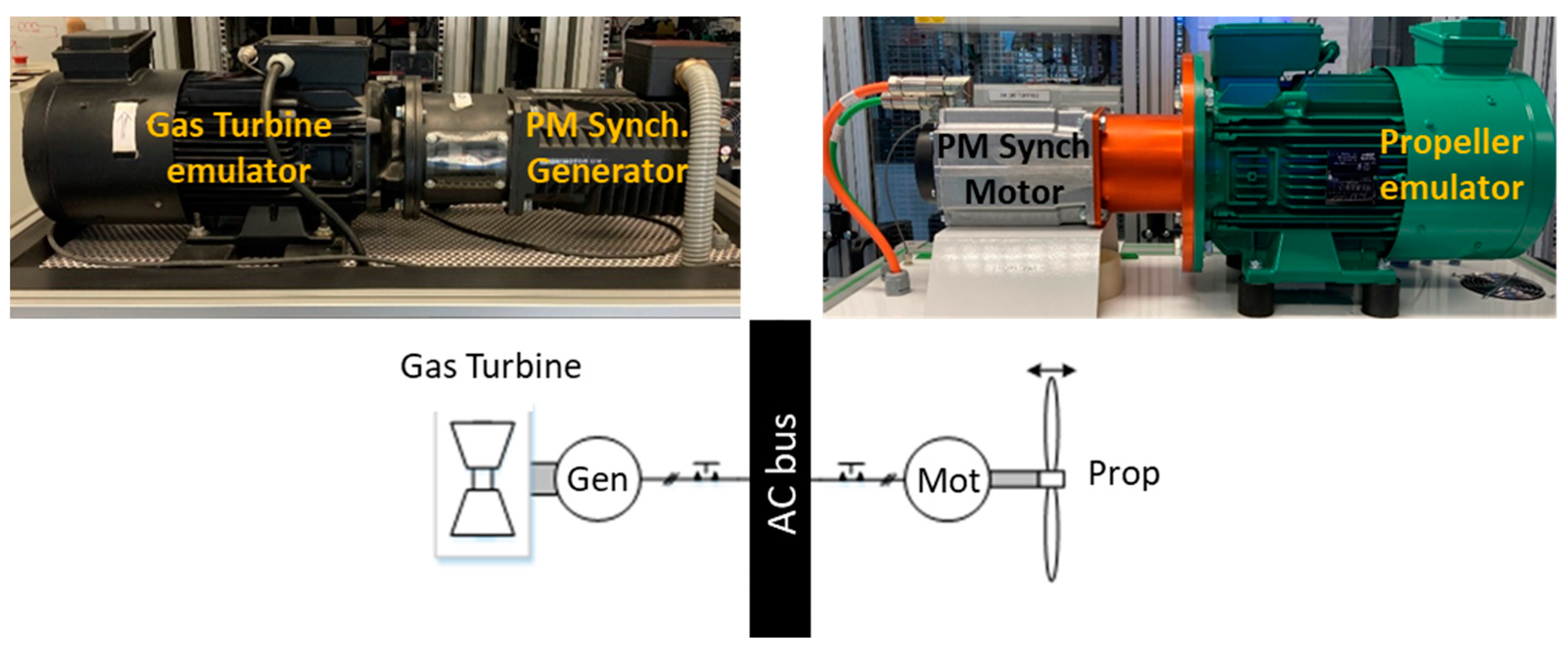
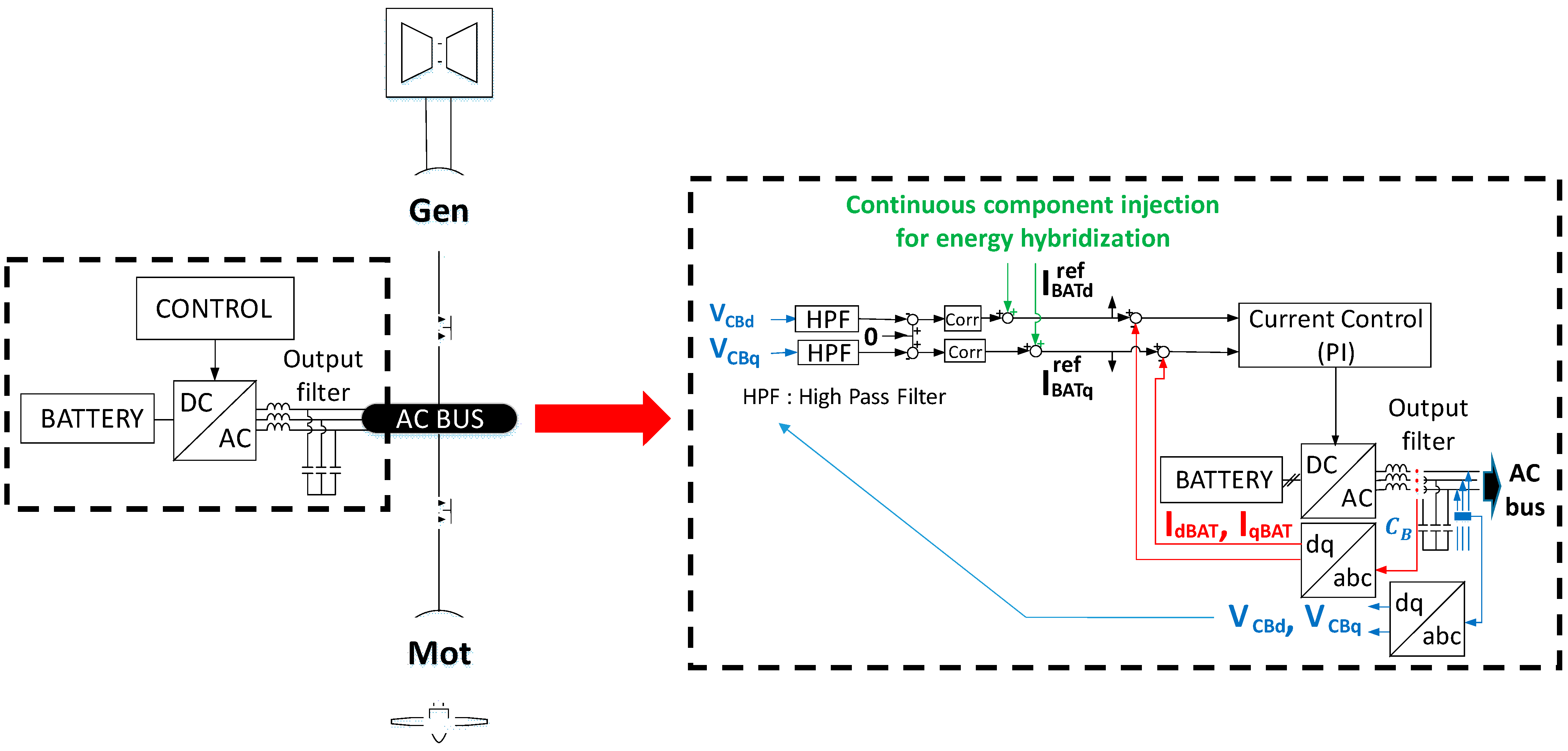
4.1. A “Power Electronic-Less” AC Architecture for Aircraft Propulsion

The literature review proposed in Section 2.4 emphasized that most of the propulsive solutions for hybrid- or full-electric aircraft powertrains are based on power electronics with a couple sources and electric machines through a DC connection, as illustrated in Figure 23a. In that example, the issue is to lower the embedded weight by suppressing the DC bus coupling and its power electronics. A “direct power electronicless” connection through an AC bus is then established between the power sources (generators) and the electric motors driving the propellers, as illustrated in Figure 23b (for single-motor connection) and Figure 23c (for multi-motor connection). In [71], only surface-mounted PMSMs were studied due to their high specific powers.
As we will describe in Section 4.2, both transient analysis and stability are at stake in a direct AC-coupled powertrain. Adding a power hybridization branch coupled with an energy storage is a relevant solution to ensure the stable operation of a typical powertrain as synthesized in Section 4.3 and illustrated in Figure 23d.
The “power electronic-less” topology of Figure 23b,c directly connects both synchronous generators and motors through an AC bus. For such structures, every electric machine operates synchronously (same speed in a steady-state situation). This direct connection also forces the voltage equality between the generator and the motor., The stator current equality is also forced in the single-motor case (Figure 23b). Only two control actions of mechanical modes exist on each side of the propulsive system:
-
At the system input, the gas turbine controls the mechanical speed of the generator, then the AC bus frequency.
-
At the system output (propeller side), pitch control of blades adjusts the propulsive thrust with respect to the blade rotation speed.
This study, detailed in [71,72], may be applied to a large number of aeronautic applications. Two examples of topologies with multiple (four or six) propellers in a series-parallel architecture are presented in Figure 24, depending on whether a “power electronic-less” AC architecture (Figure 24a) or a hybrid architecture with a battery branch in addition (Figure 24b) is considered.
Such electric distributed propulsion potentially offers advantages in terms of aerodynamics [10,11,12,13].

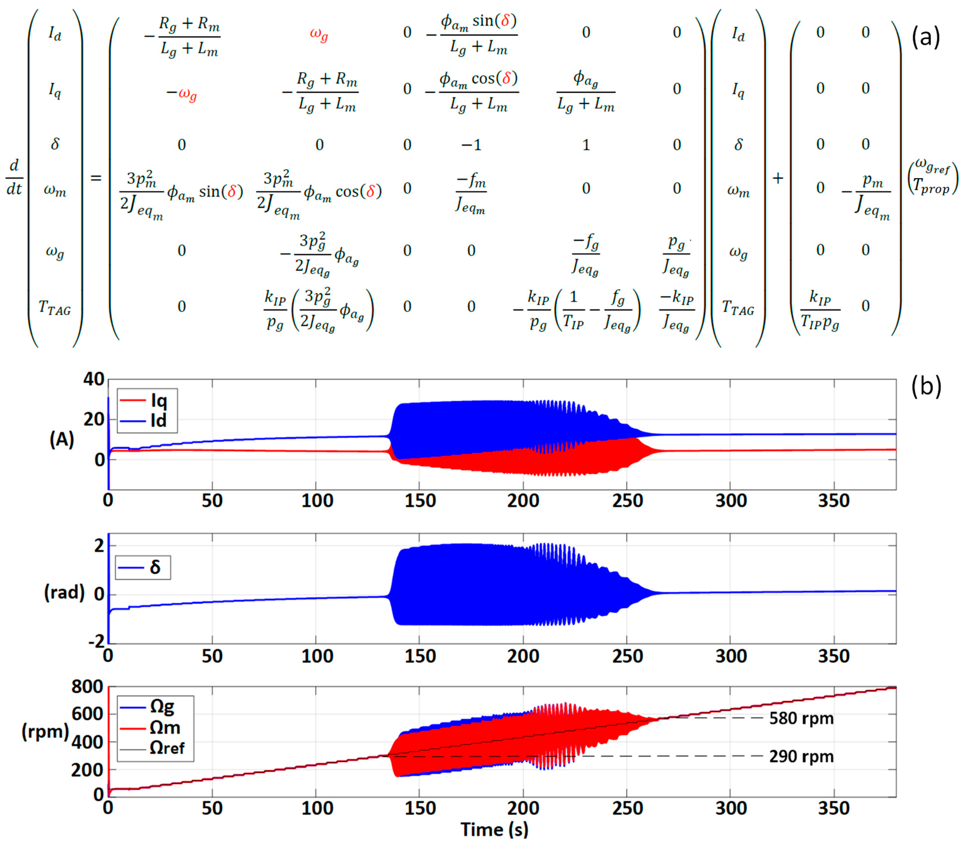
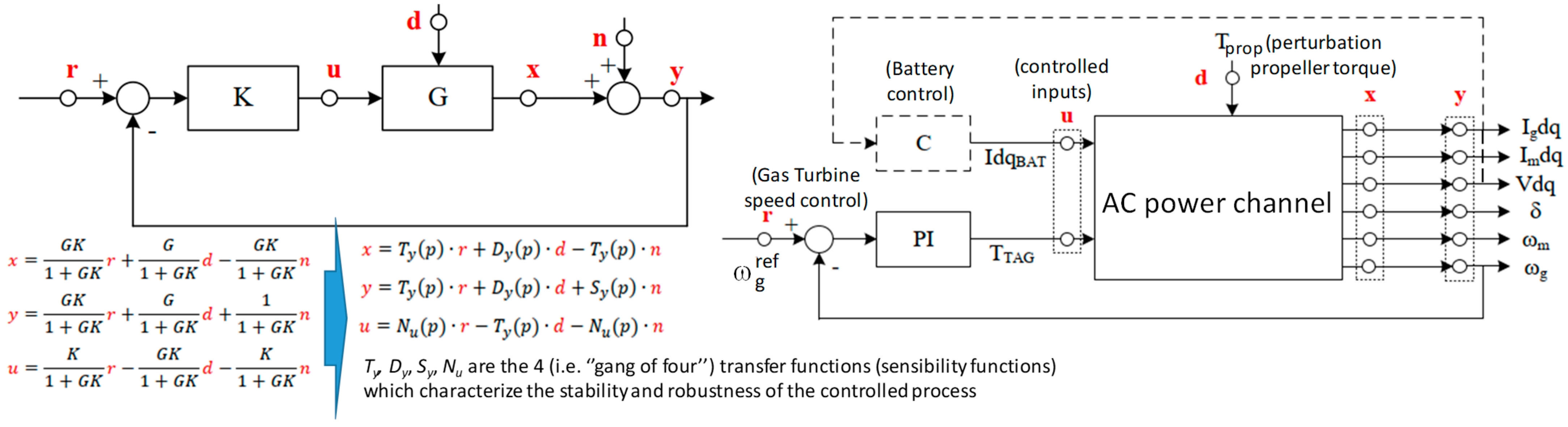
4.2. Stability Analysis of a “Power Electronic-Less” AC-Coupled Power Channel

The stability analysis of the power channel depends on its topology; the structure can be either single- (as illustrated in Figure 23b) or multi-motor (as illustrated in Figure 23c). The analytical derivation of the nonlinear model is based on Park’s reference frame. A classical Park’s (d,q) reference frame allows for modelling electric machines (generator or motor). Park’s model aligns the q axis along the electromotive force (emf), Ex = Exq, as illustrated in Figure 25. That figure represents, respectively, the rotating frame (dg, qg) for the generator and (dm, qm) for the motor.
When both machines are directly connected through an AC bus, as in Figure 23b, the phases of their emfs are shifted by the δ angle. In order to represent this direct association and to generalize the model derivation for any number of motors, every machine is modelled in the reference frame (dg, qg) related to the generator. In the following section, only a single-motor topology will be considered; the stability analysis remains complex even with that simplification. Let us note that the theoretical aspects and main analysis proposed in this section remain quite similar for multi-motor topology, as shown in [71]. The derivation of this nonlinear state model is detailed in [72], and results are shown in Figure 26a. The inputs of that state model are, respectively, the reference ( ω g r e f ) set in the speed-controlled gas turbine–generator association and the load torque ( T p r o p ) applied to the propeller. The state variables of this sixth-order model constitute the stator currents ( I d , I q ) common in the generator’s and motor’s stators directly coupled through the AC bus, the shift angle δ, the rotation speeds for the motor ( ω m ) and the generator ( ω g ), and finally the gas turbine torque ( T T A G ). The model nonlinearities are highlighted in red in the state equation. The time simulation of this state model is illustrated in Figure 26b; it emphasizes its transient behaviour, especially showing that oscillations (quasi-unstable operation) are provoked by this direct (rigid) association for certain operating points, especially inside an intermediate speed range.
A small signal linearization of this state model allowed us to trace the root locus which determines the stable/unstable zones, as illustrated in Figure 27, derived in the same operated conditions as for the time simulation in Figure 26b. In the simulation of Figure 26b, the speed range of “quasi-instability” (from 290 to 580 rpm) is almost the same as the unstable range obtained with the root locus (from 260 to 620 rpm).
To complete that analysis, an experimental test bench was developed in the LAPLACE Lab in order to validate the theoretical analysis at a reduced power scale. This test bench, shown in Figure 28, couples two electromechanical actuators that emulate the gas turbine–generator association for the first one and the electric motor–propeller set for the second. This facility physically emulates the main powertrain functions with an AC bus coupling. Figure 29 displays the experimental results in the same conditions as for the time simulation in Figure 26. These experimental results also emphasize the “quasi-instability” phenomenon as previously observed through simulation. An oscillating speed range from 300 to 560 rpm can be observed. The system behaviour is stable outside of this interval. This speed range is also close to the previous one given by the theoretical means of study. The various means of the study of the AC electric propulsion architecture are then in accordance and matched by indicating a domain of “quasi-instability”. This analysis reveals a “heavy trend”: the system stability is questioned on intermediate speeds.
Readers can find a detailed analysis of the power channel stability in [71], which reveals that several physical (stator inductances, inertia, and magnetic flux levels of both machines) and control (speed control bandwidth) factors influence the transient operation of this system. The main sizing trends for the stability improvement in the AC electric propulsion architecture can be summarized:
  • High stator inductances;
  • Low electromotive forces (proportional to magnetic fluxes);
  • High inertia of the motor set.
However, whatever the system sizing, a perfectly reliable operation (essential for aeronautic application) of that direct AC coupling of PMSMs cannot be proven. In [71], a prospect of a “scale 1” power channel with an actual design of electric machines and with refined modelling of both a propeller and a gas turbine with its control confirmed and even reinforced that issue. In that context, a supplementary power hybridization branch coupled with a storage device can be added with appropriate control, which ensures a stable operation of that hybrid power channel all over the operating range.

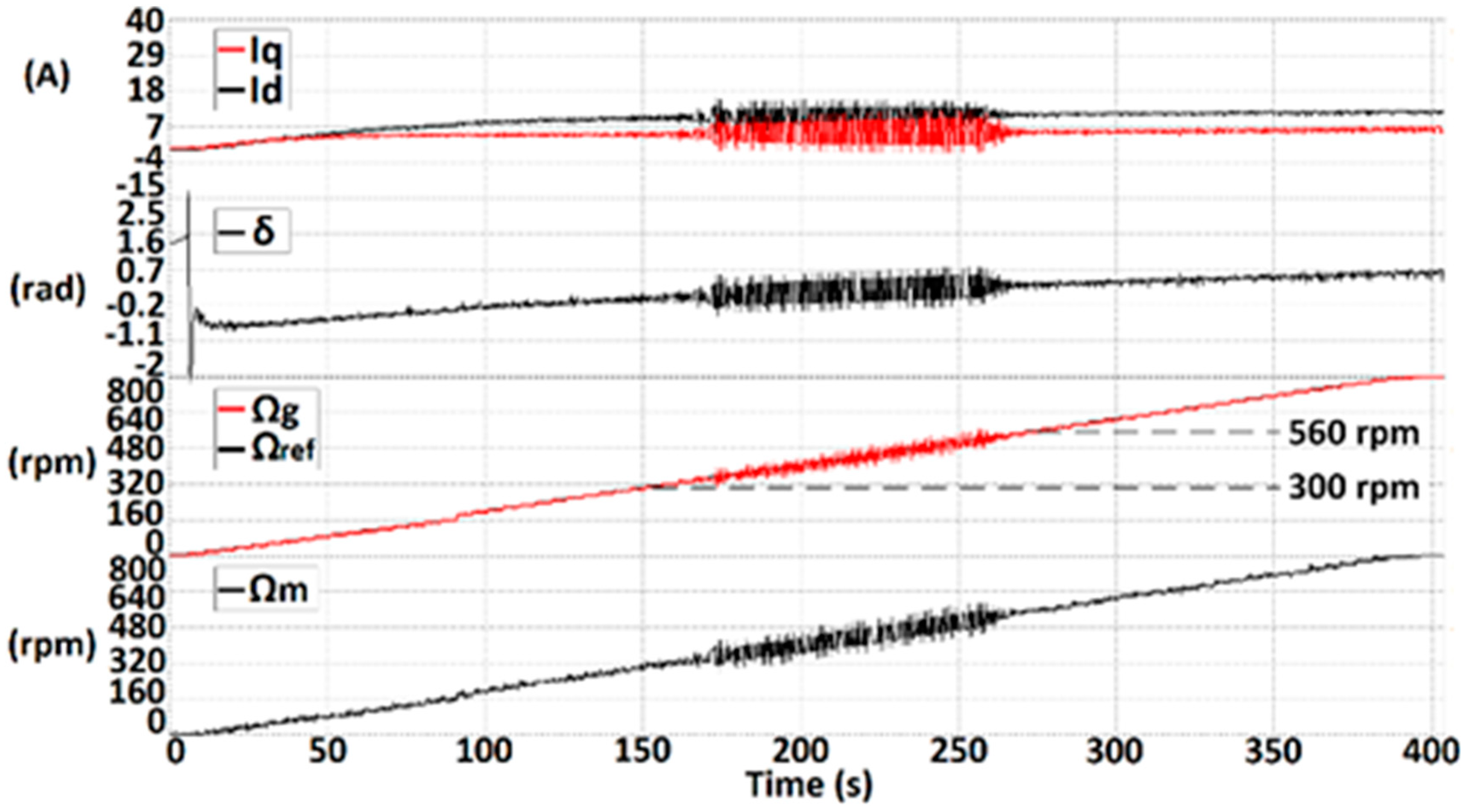
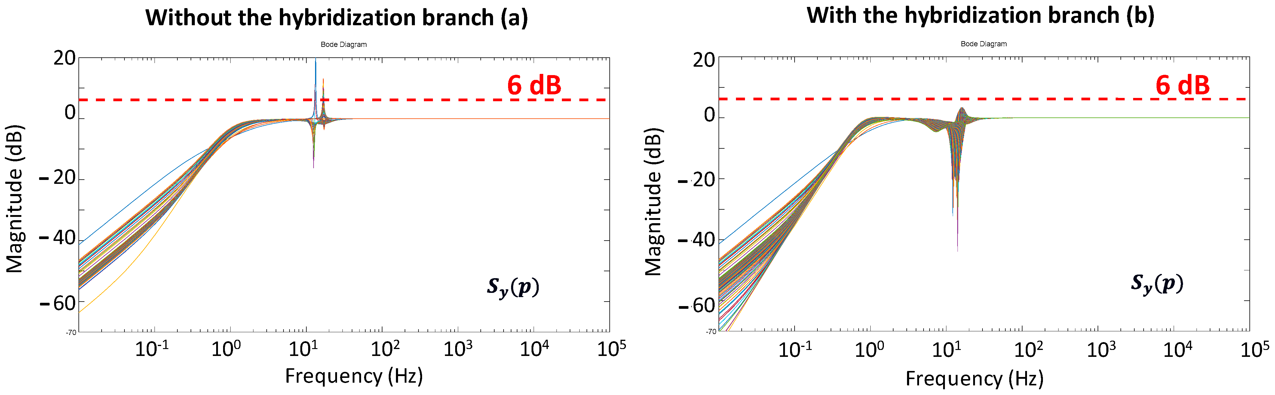
4.3. Power Hybridization of the Direct AC-Coupled Power Channel for Stable Operation

The hybrid-electric architecture illustrated in Figure 23d and in the example in Figure 24b consists of inserting a hybridization branch constituting a storage device (for example, a battery) connected to the AC bus through an inverter into the previous power channel.
The primary objective of this hybridization branch is to ensure the system’s stability regardless of the operating point. However, this additional structure may also offer supplementary degrees of freedom to optimize the aircraft operation, allowing, for example, an electric power boost in certain flight sequences or full-electric operation for “green taxiing” or electric descent. Hybridization may also help the system start the power channel to make the synchronization of the generators and motors easier [71]. In addition, like for any hybrid energy system, the auxiliary power source (here, a battery) offers capabilities in terms of fault tolerance. In that case, the battery branch may contribute to the propelling effort in the case of a gas turbine failure, for example. Furthermore, let us note that the storage sizing may be revisited in order to ensure several hybridization functionalities simultaneously. Indeed, the battery sizing that should be necessary to stabilize the hybrid-electric power channel is a priori lower than the one necessary for the power boost “without talking of fault tolerance”. This issue constitutes one of the prospects of this study, and readers can find more details [71].

4.4. Control of the Hybridization Branch for System Stabilization

The hybridization branch is firstly seen as a controlled-current source connected to the AC bus, as illustrated in Figure 30, right. The battery storage is coupled to the AC bus through an inverter with an output (L,C) filter. The battery currents are controlled with a classical PI controller in both (d = dg, q = qg) the Park’s axes referenced in the generator frame, displayed in Figure 25a. The capacitors are used to measure the voltages at the connection point.
In order to ensure the stable operation of the AC-coupled power channel, the battery current references I B a t d r e f , I B a t q r e f were considered part of the high-pass filtering (HPF) of the AC bus voltages V C B d ,   V C B q . The primary objective is to bring these current components back to zero, thanks to the proportional corrector (“corr” in Figure 30). Indeed, for cases with the quasi-unstable operation, the AC bus voltage oscillates and its HPF isolates the oscillating part of the signal as a “witness of the instability”. In fact, most of the state variables of the power channel (δ, machine currents and speeds) are other “candidate variables” that show information about the oscillating disturbance, but the bus voltages are seen as the most sensitive.
Let us note that a continuous component may be added in the reference signal (in green in Figure 30) in order to inject supplementary currents for additional energy hybridization capabilities, as introduced above.
The objective is to set the battery control parameters that ensure a “sufficient” stability margin for the hybrid power channel; the sensitivity function on the output Ty(p) is used as a stability margin criterion. The gas turbine speed is seen as the reference input “r”; the state variables “x” of the power channel are also the system outputs “y”; and the propeller torque “Tprop = d” is considered the perturbation input, the problem being to keep the system stable while the propeller torque is varied. From that vision, the hybrid power channel with its control as represented in the right part of Figure 31 can be theoretically assimilated to the control loop in the left part of Figure 31 and studied with the “Gang of four” theory [73] based on the four transfer functions (Ty, Dy, Sy, Nu).
In order to evaluate each of the four transfer functions, especially the sensitivity function on the output Ty(p), a linearization is made around a succession of the operating point. Practically, these operating points correspond to growing values of the generator speed until reaching the unstable zone. The succession of the obtained linearized transfer function of the sensitivity function Sy(p) is plotted in Figure 32 in two cases, for which the hybridization branch is connected or not. These graphs are used for the controller (“Corr”) synthesis. A satisfaction indicator consists of setting a maximum amplitude of each transfer function that should not exceed 6 dB. This criterion commonly used in industry corresponds to a multiplication of the input signal by a factor of 2 by the transfer function. In Figure 32b, one can see how the control of the battery-based hybridization branch limits the amplitude of the sensitivity function Sy(p) below the limit of 6 dB, even around resonant frequencies (here, some Hertz), which was not possible without hybridization, as displayed in Figure 32a.
Finally, Figure 33 compares the system behaviour with or without the action of the hybridization branch for both the simulation and experimental tests. This picture clearly emphasizes the stabilizing action of the battery-based hybridization branch.
Beyond these results obtained on a reduced-scale case study, the author of [71] analysed the behaviour of a “scale 1 system” with a design of a hybrid-electric power channel operating at 500 kW and with parameters typical of an actual aircraft application. In that “scale 1 system”, a more realistic gas turbine model was first considered with slow transient modes typical of that device. A high-speed PM synchronous generator and electric motor typical of aeronautic applications were also considered. Finally, a more accurate model of the propeller was simulated. In the end, this “scale 1” power channel alone (without hybridization) has confirmed and even strengthened our conclusions related to the existence of unstable zones for the AC power channel without power electronics. Adding a hybridization branch yielded the same results, showing a stable behaviour of the hybrid power channel in its whole operating range.

5. Conclusions and Future Directions

In this review, we tried synthesizing the key issues related to the electrification of future aircraft powertrains. The state of the art, described in Section 2, has shown the potential benefits of hybrid-electric powertrains, but it shows a major trend: the electric powertrain should be heavier than conventional ones, even if technological performance (integration level of devices) is sensitive to the embedded weight. In that context, it is crucial to cumulate energy gains, as detailed in the example in Section 3, for a regional hybrid aircraft, but also aerodynamic and engine optimizations. Several drivers exist to lower the embedded weight and to improve system efficiency, among them the suppression of power electronics, as illustrated in Section 4.
Major challenges still exist, primarily on a technological level, but also when coupling these multidisciplinary and complex issues inside an MDO process on an aircraft level. However, fuel burn gains remain limited with hybrid-electric powertrain due to its global weight penalty. All electric-battery-powered aircraft still have a limited range due to the current and future limitations on specific energies. In that context, hydrogen-powered aircraft seems to be an “actual breakthrough”, as recently announced by Airbus. Furthermore, if hydrogen is burnt in thermal engines or converted into electricity with fuel cells, it appears to be a clear research direction in the aviation sector, from short-range (regional) to long-distance flights. In that context, electric technologies have to be improved in terms of specific energy and power, without forgetting the system aspects of all-electric chains, of which efficiency and global weight clearly have to be optimized, including multi-physical couplings such as thermal management, hydrogen storage, and the installation of new technologies on board. NASA [74] and Airbus [75] claim innovative prospects in that direction, for example, by coupling cryogenic liquid hydrogen with superconducting components. The future zero-emission aircraft has, then, to be more deeply studied. Even if significant technological and safety (certification) challenges are in front of engineers, this is a major advancement towards greener aircraft.

Funding

Studies presented in Section 2 and Section 3 were partly funded by Airbus, especially in the framework of J. Thauvin’s thesis [10]. Research presented in Section 3 was funded by the European Union’s Horizon 2020 (Clean Sky 2 JTI) research and innovation program (2014–2024), under grant agreement No. 715483. The study illustrated in Section 4 was funded and supported by Safran Tech.

Data Availability Statement

Main data may be found in references, especially in the HASTECS book [51] for Section 3 and in [67] for Section 4.

Conflicts of Interest

The author declares no conflict of interest.

References

  1. IATA. Global Outlook for Air Transport—Times of Turbulence. Report. 2022. Available online: https://www.iata.org/en/iata-repository/publications/economic-reports/airline-industry-economic-performance---june-2022---report (accessed on 3 March 2023).
  2. Eurocontrol, Eurocontrol Forecast Update 2021–2027. 2021. Available online: https://www.eurocontrol.int/publication/eurocontrol-forecast-update-2021-2027 (accessed on 1 March 2023).
  3. IATA. Aircraft Technology Roadmap to 2050. 2019. Available online: https://www.iata.org/contentassets/8d19e716636a47c184e7221c77563c93/Technology-roadmap-2050.pdf (accessed on 6 March 2023).
  4. Sarlioglu, B.; Morris, C.T. More Electric Aircraft: Review, Challenges, and Opportunities for Commercial Transport Aircraft. IEEE Trans. Transp. Electrif. 2015, 1, 54–64. [Google Scholar] [CrossRef]
  5. Berger, R. Electric Propulsion Is Finally on the Map. Available online: https://www.rolandberger.com/en/Insights/Publications/Electric-propulsion-is-finally-on-the-map.html (accessed on 18 March 2020).
  6. Pornet, C.; Isikveren, A. Conceptual design of hybrid-electric transport aircraft. Prog. Aerosp. Sci. 2015, 79, 114–135. [Google Scholar] [CrossRef]
  7. Epstein, A.H.; O’Flarity, S.M. Considerations for Reducing Aviation’s CO2 with Aircraft Electric Propulsion. J. Propuls. Power 2019, 35, 572–582. [Google Scholar] [CrossRef]
  8. Ansell, P.J.; Haran, K.S. Electrified Airplanes: A Path to Zero-Emission Air Travel. IEEE Electrif. Mag. 2020, 8, 18–26. [Google Scholar] [CrossRef]
  9. Madonna, V.; Giangrande, P.; Galea, M. Electrical Power Generation in Aircraft: Review, Challenges, and Opportunities. IEEE Trans. Transp. Electrif. 2018, 4, 646–659. [Google Scholar] [CrossRef]
  10. Thauvin, J. Exploring the Design Space for a Hybrid-Electric Regional Aircraft with Multidisciplinary Design Optimisation Methods. Ph.D. Thesis, Institut National Polytechnique de Toulouse (Toulouse INP), Toulouse, France, 2018. Available online: https://oatao.univ-toulouse.fr/23607/1/Thauvin_jerome.pdf (accessed on 1 September 2022).
  11. Clarke, S.; Redifer, M.; Papathakis, K.; Samuel, A.; Foster, T. X-57 Power and Command System Design. In Proceedings of the 2017 IEEE Transportation Electrification Conference and Expo (ITEC), Chicago, IL, USA, 22–24 June 2017; pp. 393–400. [Google Scholar] [CrossRef]
  12. Hermetz, J.; Ridel, M.; Doll, C. Distributed electric propulsion for small business aircraft a concept-plane for key-technologies investigations. In Proceedings of the 30th Congress of the International Council of the Aeronautical Sciences, Deajeon, Republic of Korea, 25–30 September 2016; pp. 1–10. [Google Scholar]
  13. Dillinger, E.; Döll, C.; Liaboeuf, R.; Toussaint, C.; Hermetz, J.; Verbeke, C.; Ridel, M. Handling qualities of ONERA’s small business concept plane with distributed electric propulsion. In Proceedings of the 30th Congress of the International Council of the Aeronautical Sciences, Belo Horizonte, Brazil, 9–14 September 2018; pp. 1–10. [Google Scholar]
  14. Pettes-Duler, M. Integrated Optimal Design of a Hybrid-Electric Aircraft Powertrain. Ph.D. Thesis, Institut National Polytechnique de Toulouse (Toulouse INP), Toulouse, France, 2021. Available online: https://oatao.univ-toulouse.fr/28350/1/Pettes_Duler_Matthieu_.pdf (accessed on 1 September 2022).
  15. Gao, Y.; Yang, T.; Bozhko, S.; Wheeler, P.; Dragicevic, T. Filter Design and Optimization of Electromechanical Actuation Systems Using Search and Surrogate Algorithms for More-Electric Aircraft Applications. IEEE Trans. Transp. Electrif. 2020, 6, 1434–1447. [Google Scholar] [CrossRef]
  16. Zhang, X.; Bowman, C.L.; O’Connell, T.C.; Haran, K.S. Large electric machines for aircraft electric propulsion. IET Electr. Power Appl. 2018, 12, 767–779. [Google Scholar] [CrossRef]
  17. Donateo, T.; De Pascalis, C.L.; Ficarella, A. Synergy Effects in Electric and Hybrid Electric Aircraft. Aerospace 2019, 6, 32. [Google Scholar] [CrossRef]
  18. Glassock, R.; Galea, M.; Williams, W.; Glesk, T. Hybrid Electric Aircraft Propulsion Case Study for Skydiving Mission. Aerospace 2017, 4, 45. [Google Scholar] [CrossRef]
  19. Brown, G.V. Weights and efficiencies of electric components of a turboelectric aircraft propulsion system. In Proceedings of the 49th AIAA Aerospace Sciences Meeting Including the New Horizons Forum and Aerospace Exposition, Orlando, FL, USA, 4–7 January 2011. [Google Scholar] [CrossRef]
  20. Antcliff, K.R.; Guynn, M.D.; Marien, T.; Wells, D.P.; Schneider, S.J.; Tong, M.J. Mission Analysis and Aircraft Sizing of a Hybrid-Electric Regional Aircraft. In Proceedings of the 54th AIAA Aerospace Sciences Meeting, San Diego, CA, USA, 4–6 January 2016; pp. 1–18. [Google Scholar] [CrossRef]
  21. Voskuijl, M.; Van Bogaert, J.; Rao, A.G. Analysis and design of hybrid electric regional turboprop aircraft. CEAS Aeronaut. J. 2018, 9, 15–25. [Google Scholar] [CrossRef]
  22. Ye, X.I.E.; Savvarisal, A.; Tsourdos, A.; Zhang, D.; Jason, G.U. Review of hybrid electric powered aircraft, its conceptual design and energy management methodologies. Chin. J. Aeronaut. 2021, 34, 432–450. [Google Scholar]
  23. Ribeiro, J.; Afonso, F.; Ribeiro, I.; Ferreira, B.; Policarpo, H.; Peças, P.; Lau, F. Environmental assessment of hybrid-electric propulsion in conceptual aircraft design. J. Clean. Prod. 2020, 247, 119477. [Google Scholar] [CrossRef]
  24. Rings, R.; Ludowicy, J.; Finger, D.F.; Braun, C. Sizing Studies of Light Aircraft with Parallel Hybrid Propulsion Systems; Deutsche Gesellschaft für Luft-und Raumfahrt-Lilienthal-Oberth eV: Bonn, Germany, 2018. [Google Scholar] [CrossRef]
  25. Brelje, B.J.; Martins, J.R. Electric, hybrid, and turboelectric fixed-wing aircraft: A review of concepts, models, and design approaches. Prog. Aerosp. Sci. 2018, 104, 1–19. [Google Scholar] [CrossRef]
  26. Janovec, M.; Čerňan, J.; Škultéty, F.; Novák, A. Design of batteries for a hybrid propulsion system of a training aircraft. Energies 2021, 15, 49. [Google Scholar] [CrossRef]
  27. Benzaquen, J.; He, J.; Mirafzal, B. Toward more electric powertrains in aircraft: Technical challenges and advancements. In CES Transactions on Electrical Machines and Systems; CES: Winchester, NV, USA, 2021; Volume 5. [Google Scholar] [CrossRef]
  28. Saias, C.A.; Goulos, I.; Roumeliotis, I.; Pachidis, V.; Bacic, M. Preliminary Design of Hybrid-Electric Propulsion Systems for Emerging Urban Air Mobility Rotorcraft Architectures. J. Eng. Gas Turbines Power 2021, 143, 111015. [Google Scholar] [CrossRef]
  29. Hoelzen, J.; Liu, Y.; Bensmann, B.; Winnefeld, C.; Elham, A.; Friedrichs, J.; Hanke-Rauschenbach, R. Conceptual Design of Operation Strategies for Hybrid Electric Aircraft. Energies 2018, 11, 217. [Google Scholar] [CrossRef]
  30. Martins, J.; Lambe, A.B. Multidisciplinary Design Optimization: A Survey of Architectures. AIAA J. 2013, 51, 2049–2075. [Google Scholar] [CrossRef]
  31. Iwaniuk, A.; Wiśniowski, W.; Żółtak, J. Multi-disciplinary optimisation approach for a light turboprop aircraft-engine integration and improvement. Aircr. Eng. Aerosp. Technol. 2016, 88, 348–355. [Google Scholar] [CrossRef]
  32. Lefebvre, T.; Schmollgruber, P.; Blondeau, C.; Carrier, G. Aircraft conceptual design in a multilevel, multifidelity, multidisciplinary optimization process. In Proceedings of the 28th International Congress of The Aeronautical Sciences, Brisbane, Australia, 23–28 September 2012; pp. 23–28. [Google Scholar]
  33. Gazaix, A.; Gallard, F.; Gachelin, V.; Druot, T.; Grihon, S.; Ambert, V.; Guénot, D.; Lafage, R.; Vanaret, C.; Pauwels, B.; et al. Towards the Industrialization of New MDO Methodologies and Tools for Aircraft Design. In Proceedings of the AIAA/ISSMO (18th Multidisciplinary Analysis and Optimization Conference—The American Institute of Aeronautics and Astronautics), Denver, CO, USA, 5–9 June 2017; pp. 1–23. [Google Scholar]
  34. Delbecq, S.; Budinger, M.; Ochotorena, A.; Reysset, A.; Defay, F. Efficient sizing and optimization of multirotor drones based on scaling laws and similarity models. Aerosp. Sci. Technol. 2020, 102, 105873. [Google Scholar] [CrossRef]
  35. De Giorgi, F.; Budinger, M.; Hazyuk, I.; Reysset, A.; Sanchez, F. Reusable Surrogate Models for the Preliminary Design of Aircraft Application Systems. AIAA J. 2021, 59, 2490–2502. [Google Scholar] [CrossRef]
  36. Liu, Y.; Elham, A.; Horst, P.; Hepperle, M. Exploring Vehicle Level Benefits of Revolutionary Technology Progress via Aircraft Design and Optimization. Energies 2018, 11, 166. [Google Scholar] [CrossRef]
  37. Brelje, B. Multidisciplinary Design Optimization of Electric Aircraft Considering Systems Modeling and Packaging. Ph.D. Thesis, Aerospace Engineering and Scientific Computing, University of Michigan, Ann Arbor, MI, USA, 2021. [Google Scholar]
  38. Finger, D.F. Methodology for Multidisciplinary Aircraft Design under Consideration of Hybrid-Electric Propulsion Technology. Ph.D. Thesis, RMIT University, Melbourne, VIC, USA, 2020. [Google Scholar]
  39. Prigent, S.; Maréchal, P.; Rondepierre, A.; Druot, T.; Belleville, M. A robust optimization methodology for preliminary aircraft design. Eng. Optim. 2016, 48, 883–899. [Google Scholar] [CrossRef]
  40. Lei, T.; Min, Z.; Gao, Q.; Song, L.; Zhang, X. The Architecture Optimization and Energy Management Technology of Aircraft Power Systems: A Review and Future Trends. Energies 2022, 15, 4109. [Google Scholar] [CrossRef]
  41. Pettes-Duler, M.; Roboam, X.; Sareni, B. Integrated Design Process and Sensitivity Analysis of a Hybrid Electric Propulsion System for Future Aircraft. In Lecture Notes in Electrical Engineering; Springer: Berlin/Heidelberg, Germany, 2020; Volume 1, pp. 71–85. [Google Scholar]
  42. Zeaiter, A. Thermal Modeling and Cooling of Electric Motors Application to the Propulsion of Hybrid Aircraft. Ph.D. Thesis, Ecole Nationale Supérieure de Mécanique et d’Aérotechnique (ENSMA), Chasseneuil-du-Poitou, France, 2020. Available online: https://tel.archives-ouvertes.fr/tel-03158868/document (accessed on 1 September 2022).
  43. Zeaiter, A.; Fenot, M. Thermal Sensitivity Analysis of a High Power Density Electric Motor for Aeronautical Application. In Proceedings of the 2018 IEEE International Conference on Electrical Systems for Aircraft, Railway, Ship Propulsion and Road Vehicles International Transportation Electrification Conference (ESARS-ITEC), Nottingham, UK, 7–9 November 2018; pp. 1–6. [Google Scholar] [CrossRef]
  44. Touhami, S. Analytical Sizing Models to Assess the Performances of High Specific Power Electric Motors for Hybrid Aircraft. Ph.D. Thesis, Institut National Polytechnique de Toulouse (Toulouse INP), Toulouse, France, 2020. Available online: https://oatao.univ-toulouse.fr/28218/1/Touhami_Sarah.pdf (accessed on 1 September 2022).
  45. Touhami, S.; Zeaiter, A.; Fenot, M.; Lefèvre, Y.; Llibre, J.F.; Videcoq, E. Electrothermal models and design approach for high specific power electric motor for hybrid aircraft. In Proceedings of the Aerospace Europe Conference, Bordeaux, France, 25–28 February 2020. [Google Scholar]
  46. Collin, P. Design, Taking into Account the Partial Discharges Phenomena, of the Electrical Insulation System (EIS) of High Power Electrical Motors for Hybrid Electric Propulsion of Future Regional Aircraft. Ph.D. Thesis, Université de Toulouse, Toulouse, France, 2020. Available online: http://thesesups.ups-tlse.fr/4730/1/2020TOU30116.pdf (accessed on 1 September 2022).
  47. Collin, P.; Malec, D.; Lefèvre, Y. Tool to predict and avoid Partial Discharges in stator slot of rotating motors fed by inverter. In Proceedings of the Aerospace Europe Conference, Bordeaux, France, 25–28 February 2020. [Google Scholar]
  48. Erroui, N. Chaine de Conversion Forte Puissance Pour la Propulsion Aéronautique Hybride. Ph.D. Thesis, Toulouse INP, Toulouse, France, 2019. Available online: https://oatao.univ-toulouse.fr/25529/1/Erroui_najoua.pdf (accessed on 1 September 2022).
  49. Erroui, N.; Gateau, G.; Roux, N. Continuous-caliber semiconductor components. In Proceedings of the 2018 IEEE International Conference on Industrial Technology (ICIT), Lyon, France, 20–22 February 2018. [Google Scholar]
  50. Accorinti, F. Two-Phase Power Electronics Cooling Solution Design in Air Context Answer to the Objectives of the Hybrid Aircraft 2035. Ph.D. Thesis, Ecole Nationale Supérieure de Mécanique et d’Aérotechnique (ENSMA), Chasseneuil-du-Poitou, France, 2020. Available online: https://tel.archives-ouvertes.fr/tel-02993195/document (accessed on 1 September 2022).
  51. Accorinti, F.; Erroui, N.; Ayel, V.; Gateau, G.; Bertin, Y.; Roux, N.; Dutour, S.; Miscevic, M. High-efficiency cooling system for highly integrated power electronics for hybrid propulsion aircraft. In Proceedings of the 2019 IEEE 28th International Symposium on Industrial Electronics (ISIE), Vancouver, BC, Canada, 12–14 June 2019; pp. 870–877. [Google Scholar]
  52. Roboam, X.; Touhami, S.; Erroui, N.; Zeaiter, A.; Accorinti, F.; Collin, P.; Pettes-Duler, M. The HASTECS Book (Hastecs: Hybrid Aircraft: Research on Thermal and Electric Components and Systems). 2021. Available online: https://hal-univ-tlse3.archives-ouvertes.fr/hal-03407214 (accessed on 1 September 2022).
  53. Cavallo, A.; Canciello, G.; Russo, A. Integrated supervised adaptive control for the more Electric Aircraft. Automatica 2020, 117, 108956. [Google Scholar] [CrossRef]
  54. Akli, C.R. Conception Systémique d’une Locomotive Hybride Autonome. Application à la Locomotive Hybride de Démonstration et D’investigations en Energétique LHyDIE Développée par la SNCF. Ph.D. Thesis, Toulouse INP, Toulouse, France, 2008. Available online: https://oatao.univ-toulouse.fr/7710/1/akli.pdf (accessed on 25 May 2023). (In French).
  55. Ampaire Electric EELTM. Available online: https://www.ampaire.com/ (accessed on 25 May 2023).
  56. Zunum Aero. Available online: https://zunum.aero/ (accessed on 18 March 2020).
  57. Bell Nexus. Available online: https://fr.bellflight.com/products/bell-nexus (accessed on 10 March 2023).
  58. Anton, F. eAircraft: Hybrid-Elektrische Antriebe für Luftfahrzeuge. 2019. Available online: https://www.bbaa.de/fileadmin/user_upload/02-preis/02-02-preistraeger/newsletter-2019/02-2019-09/02_Siemens_Anton.pdf (accessed on 10 March 2023).
  59. Clean Hydrogen for Europe, H2 and the Future of Aircraft. 2022. Available online: https://hydrogeneurope.eu/h2-and-the-future-of-aircraft/ (accessed on 10 March 2023).
  60. Sadey, D.J.; Taylor, L.M.; Beach, R.F. Proposal and Development of a High voltage Variable Frequency alternating Current Power System for Hybrid Electric Aircraft. In Proceedings of the 14th International Energy Conversion Engineering Conference, Salt Lake City, UT, USA, 25–27 July 2016. [Google Scholar] [CrossRef]
  61. Sadey, D.J.; Bodson, M.; Csank, J.T.; Hunker, K.R.; Theman, C.J.; Taylor, L.M. Control Demonstration of Multiple Doubly-Fed Induction Motors for Hybrid Electric Propulsion. In Proceedings of the 53rd AIAA/SAE/ASEE Joint Propulsion Conference, Atlanta, GA, USA, 10–12 July 2017. [Google Scholar] [CrossRef]
  62. Himmelmann, R.A. Variable Speed AC Bus Powered Tail Cone Boundary Layer Ingestion Thruster. U.S. Patent US20180265206A1, 20 September 2018. [Google Scholar]
  63. Blackwelder, M.J.; Rancuret, P.M. Multiple Generator Synchronous Electrical Power Distribution System. U.S. Patent EP3197043A1, 26 July 2017. [Google Scholar]
  64. Armstrong, M.; Blackwelder, M. Combined AC and DC Turboelectric Distributed Propulsion System. U.S. Patent EP3318492A1, 9 May 2018. [Google Scholar]
  65. Armstrong, M.; Blackwelder, M.J.; Bollman, A.M. Synchronizing Motors for an Electric Propulsion System. U.S. Patent US20160365810A1, 15 December 2016. [Google Scholar]
  66. Bachmann, C.; Bergmann, D.; Bachmaier, G.; Gerlich, M.; Pais, G.; Vittorias, I. Propellerantrieb und Fahrzeug, Insbesondere Flugzeug. Germany Patent DE102015213580A1, 26 January 2017. [Google Scholar]
  67. Rougier, F.; Viguier, C. Système Electrique Pour Canal Propulsif Synchrone. France Patent FR3092948A1, 21 August 2020. [Google Scholar]
  68. Pettes-Duler, M.; Roboam, X.; Sareni, B.; Lefevre, Y.; Llibre, J.-F.; Fénot, M. Multidisciplinary Design Optimization of the actuation system of a hybrid electric aircraft powertrain. Electronics 2021, 10, 1297. [Google Scholar] [CrossRef]
  69. Petrowski, A. A clearing procedure as a niching method for genetic algorithms. In Proceedings of the IEEE International Conference on Evolutionary Computation, Nagoya, Japan, 20–22 May 1996; pp. 798–803. [Google Scholar] [CrossRef]
  70. Pettes-Duler, M.; Roboam, X.; Sareni, B. Integrated Optimal Design of a hybrid electric aircraft powertrain of future aircraft. Energies 2022, 15, 6719. [Google Scholar] [CrossRef]
  71. Richard, A. Conception D’architectures et Dimensionnement de Systèmes Propulsifs Aéronautiques, Etude des Canaux Propulsifs AC Synchrones. Ph.D. Thesis, Toulouse INP, Toulouse, France, 1 February 2023. (In French). [Google Scholar]
  72. Richard, A.; Roboam, X.; Rougier, F.; Roux, N.; Piquet, H. AC Electric Powertrain without Power Electronics for Future Hybrid Electric Aircraft: Architecture, Design and Stability Analysis. Appl. Sci. 2023, 13, 672. [Google Scholar] [CrossRef]
  73. Zimenko, K.; Polyakov, A.; Efimov, D.; Kremlev, A. Frequency Domain Analysis of Control System Based on Implicit Lyapunov Function. In Proceedings of the Chez IEEE—2016 European Control Conference (ECC), Aalborg, Denmark, 29 June–1 July 2016. [Google Scholar] [CrossRef]
  74. Airbus to Boost ‘Cold’ Technology Testing as Part of Its Decarbonisation Roadmap—Commercial Aircraft—Airbus. Available online: https://www.airbus.com/newsroom/press-releases/en/2021/03/airbus-to-boost-cold-technology-testing-as-part-of-its-decarbonisation-roadmap.html (accessed on 2 June 2021).
  75. Schneider, S. Some NASA Perspectives on H2. H2@Airports Workshop. 4 November 2020. Available online: https://www.energy.gov/sites/prod/files/2020/12/f81/hfto-h2-airports-workshop-2020-schneider.pdf (accessed on 25 May 2023).
Figure 1. Global air passenger traffic: historic revenue passenger kilometers (RPK) and forecasts.
Energies 16 06831 g001
Figure 2. Schematic CO2 emissions reduction roadmap.
Energies 16 06831 g002
Figure 3. Evolution of project number for electrically propelled aircraft.
Energies 16 06831 g003
Figure 4. Some electrically propelled aircraft projects.
Energies 16 06831 g004
Figure 5. “Snowball effect” on conventional architecture with weight addition and fuel burn effects.
Energies 16 06831 g005
Figure 6. Numerous interactions to be integrated: “necessity of an MDO process”.
Energies 16 06831 g006
Figure 7. Potential benefits with hybridization in terms of (a) engine optimization, (b) aerodynamics, and (c) energy efficiency [10].
Energies 16 06831 g007
Figure 8. Indicators PHP (upper part) and EHP (lower part) to set the “difficulty of hybridizing the driving mission”.
Energies 16 06831 g008
Figure 9. Hybrid-electric and full-electric architectures.
Energies 16 06831 g009
Figure 10. Some projects involving hybrid-electric architectures are positioned in the (HP, HE) plan.
Energies 16 06831 g010
Figure 11. Technology target setting for battery-powered full-electric aircraft.
Energies 16 06831 g011
Figure 12. Simplified synopsis of a single-channel hybrid-electric powertrain illustrating snowball effects on weights (each added “kg” at device level involves an increase in the global embedded weight (MTOW) which also involves a subsequent increase in structure and, consequently, of the fuel weight necessary for the flight).
Energies 16 06831 g012
Figure 13. Relative gains on MTOW (up) and fuel burn (down) with respect to the technological performance of electric devices (percentage variations are related to the lower-performance “2025 Target”).
Energies 16 06831 g013
Figure 14. The HASTECS project.
Energies 16 06831 g014
Figure 15. Design of highly integrated power electronics (a) with cooling (b).
Energies 16 06831 g015
Figure 16. Design of highly integrated electric motors (a) with cooling device (b); influence of thermal transients (c).
Energies 16 06831 g016aEnergies 16 06831 g016b
Figure 17. Local optimization of the high-speed SMPMSM actuator weight: (a) the process and (b) results without and with internal cooling inside slots.
Energies 16 06831 g017
Figure 18. Flight mission definition to set the trade-off for a regional flight (400 nm) with a “simple EMS” (full-electric taxing and descent and full-thermal climb and cruise); comparison table between best power or energy-oriented batteries and fuel cell with liquid cryogenic H2.
Energies 16 06831 g018
Figure 19. Multidisciplinary design optimization (MDO) process of the hybrid-electric powertrain.
Energies 16 06831 g019
Figure 20. System integration with environment couplings and snowball effect. Linearization between thrust and global embedded weight (MTOW).
Energies 16 06831 g020
Figure 21. Integrated optimal design of the whole powertrain system: (a) optimisation formulation, (b) decision variables and constraints, (c) comparative results from optimisation.
Energies 16 06831 g021aEnergies 16 06831 g021b
Figure 22. Trade-off assessing hybrid-electric aircraft with respect to a conventional aircraft as a reference point.
Energies 16 06831 g022
Figure 23. Topologies for electric powertrain: (a) with power electronics coupling; (b) “power electronic-less” coupling with single-motor connection; (c) “power electronic-less” coupling with multi-motor connection; (d) AC coupling with hybridization branch.
Energies 16 06831 g023
Figure 24. Two examples of architectures without power electronics: with 6 propellers and with generators and motors directly coupled through an AC bus (a); with battery (BAT) hybridization and 4 propellers (b).
Energies 16 06831 g024
Figure 25. Park’s reference frames: (a) generator voltage and current vectors in the generator reference frame (dg, qg); (b) motor voltage and current vectors in the motor reference frame (dm, qm); (c) generator and motor voltage and current vectors with phase shift in the generator reference frame (dg, qg).
Energies 16 06831 g025
Figure 26. Nonlinear state model of the single generator–motor association directly coupled through an AC bus (a) and time simulation with respect to variable stages of the generator speed (b).
Energies 16 06831 g026
Figure 27. Root locus based on the small-signal model with respect to the generator speed (blue crosses in Rpm). Dashed lines illustrate iso-values of the system damping, and the red line indicates the limit between the stable and the unstable zone.
Energies 16 06831 g027
Figure 28. Reduced-power-scale test bench for AC powertrain functional emulation.
Energies 16 06831 g028aEnergies 16 06831 g028b
Figure 29. Experimental test with respect to variable stages of the generator speed with a bandwidth of 1 Hz for the generator speed control.
Energies 16 06831 g029
Figure 30. Hybridization branch (left) and its control structure (right).
Energies 16 06831 g030
Figure 31. Hybrid-electric AC power channels are controlled and stabilized by means of the “gang of four” theory [73].
Energies 16 06831 g031
Figure 32. Bode diagram of the sensitivity function on the output Ty(p) as the indicator of the controller action on the system stability.
Energies 16 06831 g032
Figure 33. System behaviour for growing speeds: (a) simulation without hybridization; (b) simulation with hybridization; (c) experiments without hybridization; (d) experiments with hybridization.
Energies 16 06831 g033
Table 1. Comparison of the “difficulty of hybridizing the driving mission” for different transport modes.
CarTrainShipAircraft
UrbanRural RoadMotorway 150 km/hLocal
Service
SwitchingUrban TransportContainerPassenger FerryRegional 200 nm
PHP (%)948574658391436333
EHP (mHz)66301232920n/an/a0.22
Table 2. Electrical component assessments according to EIS (entry into service).
EIS 2025EIS 2030+
Electric machineSpecific power
Efficiency
7 kW/kg
96%
11 kW/kg
98.5%
Power ElectronicsSpecific power15 kW/kg
99%
20 kW/kg
99.5%
BatterySpecific energy
Max charge/discharge (C rate)
Efficiency
280 Wh/kg
2/5
90%
380 Wh/kg
2/5
95%
CablesDC bus voltage540 V1500 V
Table 3. Electric component assessments (SP: specific power; SE: specific energy).
2025 Target2035 Target20XX Target
eMotor/eGenerator
SP + cooling
Efficiency
5 kW/kg
96%
10 kW/kg
98.5%
15 kW/kg
99%
Power Electronics
SP + cooling
Efficiency
15 kW/kg
98%
25 kW/kg
99.5%
35 kW/kg
99.8%
Fuel Cell—Liquid H2
H 2 + tank   S E
Auxiliary S P
Stack S P
3.3 kWh/kg
1.3 kW/kg
4 kW/kg
DC Bus
Ultra H V D C 2000 V
Table 4. Comparison between best power- or energy-oriented batteries and fuel cells with liquid cryogenic H2.
LTONMC Solid StateFC System with Liquid H2
Perspectives (5–10 years)Cell level~180–200 Wh/kg~650 Wh/kg~1000 Wh/kg
System level~100 Wh/kg~325 Wh/kg~560 Wh/kg
LTO: lithium titanium oxide; NMC: nickel manganese cobalt; FC: fuel cell.
Disclaimer/Publisher’s Note: The statements, opinions and data contained in all publications are solely those of the individual author(s) and contributor(s) and not of MDPI and/or the editor(s). MDPI and/or the editor(s) disclaim responsibility for any injury to people or property resulting from any ideas, methods, instructions or products referred to in the content.

