Article

Optimization Analysis on the Transmission Characteristics of Multipurpose Power Transmission Devices

1
The State key Laboratory of Mechanical Transmission, Chongqing University, Chongqing 400044, China
2
The State key Laboratory of Fluid Power and Mechatronic Systems, Zhejiang University, Hangzhou 310027, China
3
Automotive Engineering Research Institute, Jiangsu University, Zhenjiang 212013, China
*
Author to whom correspondence should be addressed.
Energies 2023, 16(19), 6989; https://doi.org/10.3390/en16196989
Submission received: 11 August 2023 / Revised: 24 September 2023 / Accepted: 29 September 2023 / Published: 7 October 2023
(This article belongs to the Section F: Electrical Engineering)

Abstract

:
Particularly crucial throughout the mode transition procedure is the transmission properties of hydro–mechanical composite transmission devices. This paper describes a multipurpose power transmission device that integrates hydrostatic, hydro-mechanical, and mechanical transmission and mainly discusses the transmission characteristic optimization problem from the perspective of speed regulation characteristics, shift strategy, and efficiency characteristics. The kinematic and dynamic analysis of the transmission system, the assembly scheme, and relevant parameters of the power transmission device are analyzed, and the speed regulation characteristic curve is obtained. The shift strategy of power transmission devices involving clutches and brakes during the whole speed regulation process and the best switch time of each component are found. The efficiency expression of the static pressure system is obtained from the efficiency model of the pump-control-motor system, and the efficiency of the multi-purpose power transmission device is obtained using the efficiency definition method. The fitting curves of hydrostatic system efficiency are determined using experimental data, and the efficiency of the hydro–mechanical composite power transmission system is obtained using the conversion mechanism method. The results show that the shift quality of power transmission devices can be improved greatly by controlling the switch sequence of clutches and brakes reasonably.

1. Introduction

With the development of more and more hydro-mechanical devices made of different parts or material-sending apparatuses, different structures have been used, but having good efficiency has always been the desired end purpose, which is influenced by multiple factors [1,2,3].
In 2018, Antonio and Alarico conducted a study on the efficiency of engines equipped with HMCVT. They proposed a joint control strategy for the engine’s HMCVT, which improved the fuel economy and transmission efficiency of the entire system [4]. In 2021, Guangqing Zhang and Kaixing Wang conducted a study on a secondary HMCVT transmission system suitable for tractor-towing conditions. This system better reflects the steady-state characteristics of the HMCVT transmission system. By utilizing the gear ratios and torque ratios between various components, they derived a method to calculate the efficiency of the HMCVT system [5]. In 2022, Jiang Li and Yirong Zhao analyzed the efficiency characteristics of the dual-planet HMCVT, which is also analyzed in this study. They also examined the efficiency distribution area under different loads, providing theoretical support for improving the efficiency of multi-planet HMCVT tractors [6].
The composite transmission that has emerged in recent years can provide a single power flow transmission advantage, which can avoid disadvantages. Take the hydro-mechanical composite transmission for example, the transmission system composed of a hydrostatic transmission device and mechanical transmission device in series can realize speed variation, direction change, and overload protection with the hydrostatic transmission path and extend the coverage area of output speed and torque with the mechanical transmission path. This transmission mode expands the available efficient zone of the system; however, it cannot increase the peak efficiency of the system. When the transmission system is composed of a hydrostatic transmission device and mechanical transmission device in parallel, a variable speed drive system with stepless speed regulation performance and a wide range of efficient distribution can be obtained. A speed change transmission device with multiple transmission modes is applicable to mobile machinery with great speed variation between operation conditions and transportation conditions [7,8,9,10].
This article describes a device for power transmission that is multifunctional, utilizing pure hydraulic transmission to ensure a smooth start of the vehicle during starting conditions. To ensure a long time efficient stepless speed change, the vehicle uses a hydro-mechanical transmission for its working conditions. Mechanical transmission is used to ensure the efficient operation of the vehicle under transportation conditions [11,12].

2. Design Scheme of the Multipurpose Power Transmission Device

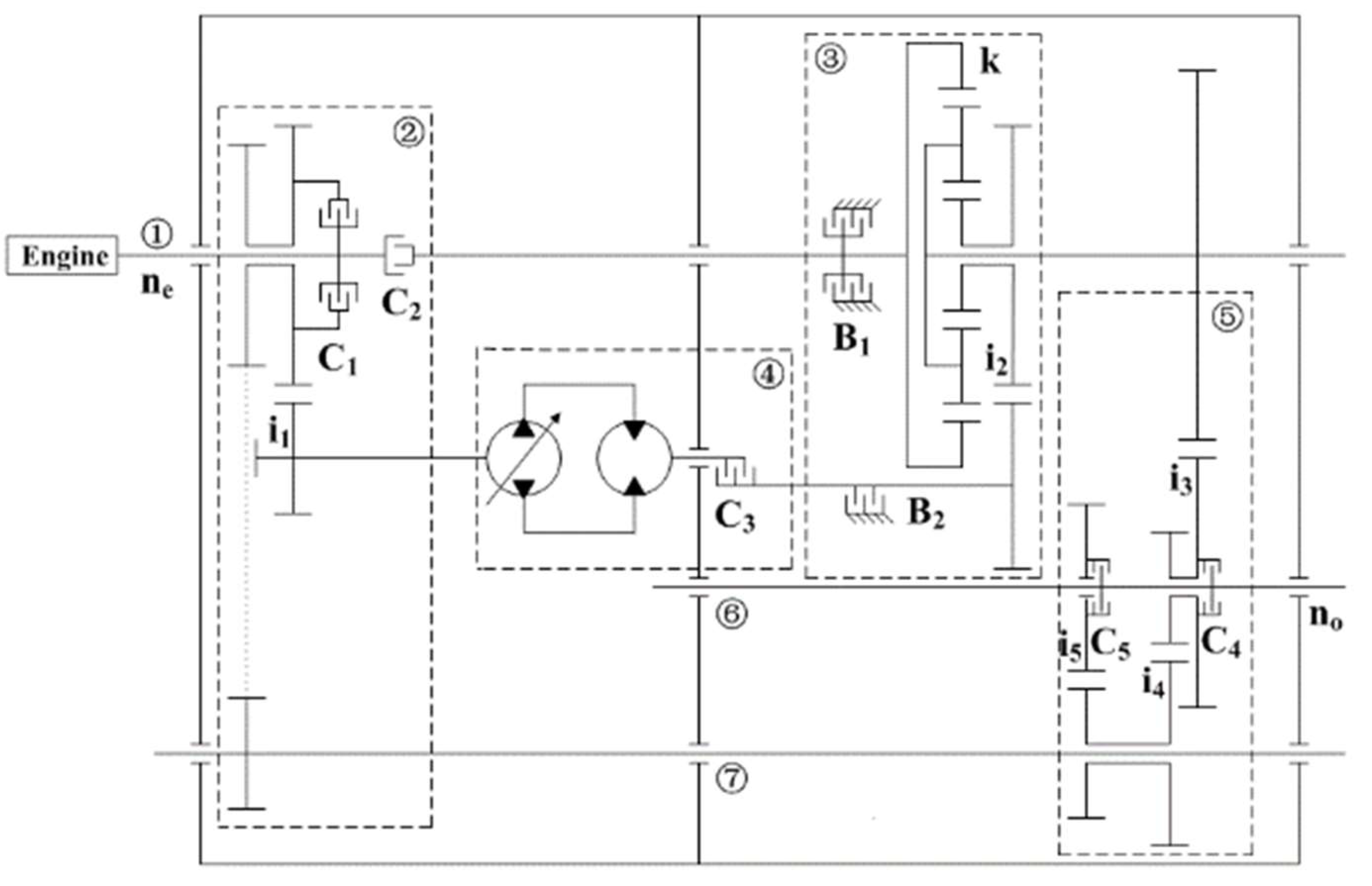
2.1. Structure Scheme

A hydro-mechanical composite transmission device was designed (Patent number: ZL201410337988.0). A structure diagram and main components of the multipurpose power transmission device are shown in Figure 1, where ② the mechanical transmission assembly mainly includes an input clutch for the mechanical transmission system; ③ the single planetary gear confluence mechanism assembly mainly includes a gear ring, a sun wheel, a planet carrier, a brake for the gear ring, a brake for the sun wheel, an input shaft for the gear ring, and an output shaft for the planet carrier; ④ the hydrostatic transmission assembly mainly includes an input clutch for the hydrostatic transmission system, gear pairs for the hydrostatic transmission system, a variable displacement pump, a fixed displacement motor, an output clutch, and an output shaft for the hydrostatic transmission system; and ⑤ the shift mechanism assembly mainly includes clutches for high range and low range and related speed variation gear pairs. The characteristics of the multipurpose power transmission device can be described as follows: a hydrostatic transmission is used to start the vehicle, a hydro-mechanical composite transmission is used to realize stepless speed regulation, and a mechanical transmission is used to realize high-efficiency transmission. In general, the hydrostatic transmission mode and the hydro-mechanical transmission mode are often used in the operation condition, and some power is outputted from the power output shaft to drive other mechanisms. The mechanical transmission mode is usually used in the transporting condition. This kind of speed regulation transmission device can switch transmission modes as required, in order to improve the service performance of a multipurpose power transmission device [13].
The main components of the multipurpose power transmission device include ① an input shaft; ② mechanical transmission assembly; ③ single planetary gear confluence mechanism assembly; ④ hydrostatic transmission assembly; ⑤ shift mechanism assembly; ⑥ and output shaft; and ⑦ a power output shaft.
The component status of the multipurpose power transmission device is shown in Table 1.

2.2. Parameters Design

2.2.1. Kinematic and Kinetic Analysis of the Vehicle System

The total resistance of the vehicle operating system can be expressed as follows [14,15,16]:
F x = F f + F w + F i + F j
When the vehicle is running at low speed, F w and F j can be neglected according to the test data. For the design, we take into account that F t m a x should be larger than F x , that is:
{ F t max F x max F x = G f cos α + G sin α
In this paper, we use G = 58800 N , f [ 0.01,0.30 ] , and α [ 0,3 0 ° ] . F x increases as f and α increase in the field of definition. We can deduce that F x m a x using calculation.
F t m a x is rarely more than F ϕ , which can be expressed as follows:
F ϕ t m a x
Test data for f and ϕ are shown in Table 2.
The transmission ratio is defined as the ratio of input speed to output speed. The transmission ratio of the multipurpose power transmission device in this paper can be expressed as follows:
i g = n e n o
The displacement ratio is defined as the ratio of pump displacement to motor displacement. The volume speed-modulating loop studied in this paper possesses the following characteristic:
e = D P D M = D P D P m a x
The vehicle speed expression is as follows:
v = 0.377 n e r q i g i 0 i L B
In this paper, we use r q = 0.400 m , i 0 = 4.0 , and i L B = 5.6 .

2.2.2. Parameters Analysis of the Hydrostatic System

By comparison, the series product SAUER_DANFOSS055 can be chosen as the hydrostatic system. At the input end of the power transmission device, the expression should meet the following conditions [17,18,19]:
{ n e max i 1 n P max T e max i 1 T P max
The output torque of the variable pump can be expressed as follows:
T P = D P Δ p P η P m 20 π
According to Equations (7) and (8), we can infer that i 1 [ 0.59,1.16 ] . In order to improve the utilization of the hydrostatic system, we use i 1 = 0.67 in this paper.

2.2.3. Transmission Ratio of Each Range

Range F1 uses a hydrostatic transmission, and the transmission ratio of range F1 can be expressed as follows:
i g F 1 = ( k + 1 ) i 1 i 2 i 3 e
Range F2 uses a hydro-mechanical composite transmission, and the transmission ratio of range F2 can be expressed as follows:
i g F 2 = ( k + 1 ) i 3 i 4 i 5 e i 1 i 2 + k
Range F3 uses a mechanical transmission, and the transmission ratio of range F3 can be expressed as follows:
i g F 3 = ( k + 1 ) i 3 k
Range R uses a hydrostatic transmission, and the transmission ratio of range R can be expressed as follows:
i g R = ( k + 1 ) i 1 i 2 i 3 e
According to the choice of the characteristic parameter for the planet gear, and the analysis of speed regulation characteristics, the relevant parameters can be obtained as k = 2.5 , i 1 = 0.67 , i 2 = 1.5 , i 3 = 0.5 , i 4 = 2.0 , and i 5 = 3.0 .
The relationship curves between the transmission ratio and the displacement ratio are shown in Figure 2.
A starting, operation, and braking check should be carried out at the output end of the power transmission device.
In the hydrostatic range, the power transferred from the transmission device can start the vehicle, namely:
T M m a x || 2 3 F q t m a x i 0 i L B o m a x
In the hydro-mechanical range, the power transferred from the transmission device can overcome the ground adhesive force, namely:
T M m a x || 2 3 4 5 F q t m a x i 0 i L B o m a x
The hydrostatic range can afford the desired torque when Z 0.1 + 0.85 ( ϕ 0.2 ) , namely:
T M m a x || 2 3 Z G r q i 0 i L B
According to Equations (13)–(15), we can calculate that T M m a x . Given that the displacement of the motor is equal to the maximum displacement of the pump, the hydrostatic components selected in this paper meet the design requirement. A promising power transmission device should have perfect transmission characteristics, including speed regulation characteristics, shift characteristics, and efficiency characteristics.

3. Transmission Characteristics of the Multipurpose Power Transmission Device

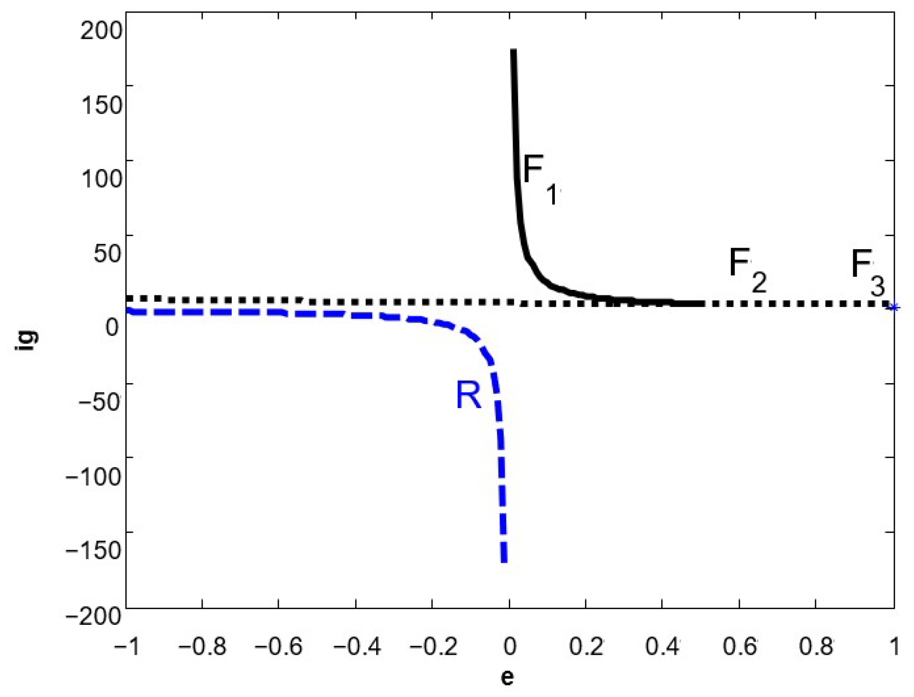
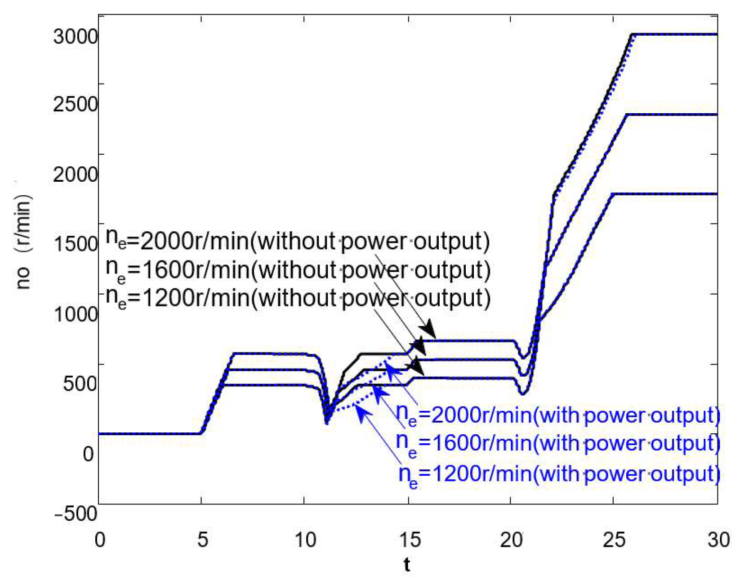
3.1. Speed Regulation Characteristics

The main parameters of the multipurpose power transmission device can be set as follows: engine speed n e = 1600   r / min , load torque T o = 400   Nm , oil circuit pressure p L = 40   bar , and flow of speed regulating valve Q v = 4   L / min . The displacement ratios of the hydrostatic system and the ranges at different time periods are shown in Table 3 [20,21,22].
The intermediate shaft (shaft 3) and output shaft (shaft 4) speed curves of the multifunctional power transmission device are shown in Figure 3.
Figure 3 shows that output shaft speed produces a fluctuating phenomenon at the switching points (10 s and 20 s), and the general speed regulation characteristic is perfect. So, the optimization for the shift point characteristic is the focus of this study. The minimum speed of the output shaft is 123.14 r/min at the time point of 11.14 s, which means that the speed drop amplitude at position I is 73.03%. The minimum speed of the output shaft is 414.64 r/min at the time point of 20.63 s, which means that the speed drop amplitude at position Ⅱ is 22.12%. The solution of the shift switching optimization problem in the two positions plays a decisive role in improving shift quality.
Jerk is defined as the rate of change in the longitudinal acceleration of the vehicle. j 3 can be regarded as the jerk in the rear axle caused by the intermediate shaft. Similarly, j 4 can be regarded as the jerk in the rear axle caused by the output shaft. The intermediate shaft and output shaft shift jerks are generated by the engagement and disengagement of switch components, which have a close relationship with the related shafts. The intermediate shaft and output shaft shift jerks of the power transmission device are shown in Figure 4.
Relatively large jerks have been heavily focused in the seven positions in Figure 4. The jerks in positions Ⅰ and Ⅳ are generated by the change in the hydrostatic system displacement ratio. Although the change rate of the displacement ratio is large, it has little influence on the shift jerks. The jerks in position Ⅱ are generated by the engagement of Clutch C5 at the time point of 11.15 s. At this moment, j3max = −7.76 and j4max = 18.66, where the negative sign means both are in opposite directions. The jerk in position Ⅲ is generated by the engagement of Clutch C2 at the time point of 12.03 s. At this moment, j3max = −9.38 and j4max = −8.85; thereafter, Clutch C4 and Brake B1 complete the switching process quickly. The jerk in position Ⅴ is generated by the engagement of Brake B2 at the time point of 20.55 s. At this moment, j3max = 15.82. Given that the hydrostatic system can absorb braking energy, there is no obvious impact at shaft 4. The jerk in position Ⅵ is generated by the engagement of Clutch C4 at the time point of 22.28 s. At this moment, j3max = 11.13 and j4max = −6.28. The jerk in position Ⅶ is generated by the engagement of Clutch C5 at the time point of 23.15 s. At this moment, j3max = −3.17 and j4max = −8.33. Generally speaking, the jerk caused by shift actuator disengagement is larger than that caused by shift actuator engagement. Clutch C1 completes the disengaging process between the engaging process of Brake B2 and Clutch C4. Obviously, the diagram showing the jerk can well reflect the shift process and quality.

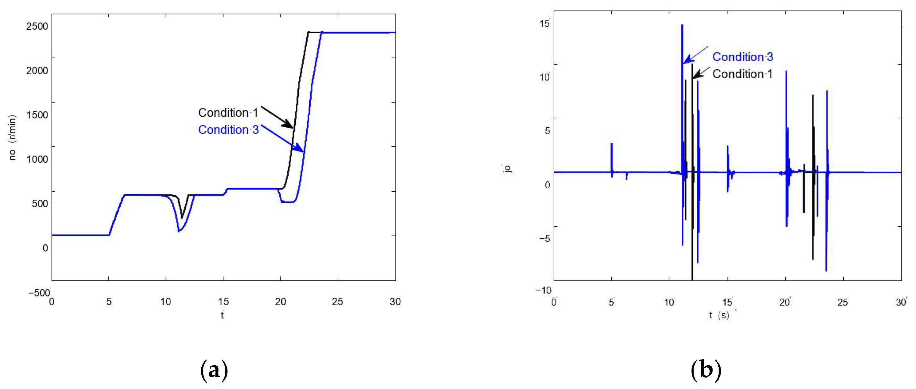
3.2. Shift Characteristic

The multipurpose power transmission device described in this paper includes seven shift actuators (five clutches and two brakes), and there are four shift actuators (three clutches and one brake) to complete the shift switch each time. Orthogonal tests (four factors and three levels) can be used to solve the optimization problem of shift component sequences and identify the best and worst working conditions. According to the analysis, three typical working conditions were obtained as follows:
Condition 1 (the best condition): Hydrostatic range→Hydro-mechanical range. Clutch C2 is engaged at the time point of 10.0 s, Clutch C4 is disengaged at the time point of 10.0 s, Clutch C5 is engaged at the time point of 10.5 s, and Brake B1 is disengaged at the time point of 10.0 s. Hydro-mechanical range→Mechanical range. Clutch C1 is disengaged at the time point of 20.5 s, Clutch C4 is engaged at the time point of 19.5 s, Clutch C5 is disengaged at the time point of 19.5 s, and Brake B2 is engaged at the time point of 20.5 s.
Condition 2 (the common condition): Hydrostatic range→Hydro-mechanical range. Clutch C2, C4, and C5 and Brake B1 are switched at the time point of 10.0 s. Hydro-mechanical range→Mechanical range. Clutch C1, C4, and C5 and Brake B2 are switched at the time point of 20.0 s.
Condition 3 (the worst condition): Hydrostatic range→Hydro-mechanical range. Clutch C2 is engaged at the time point of 9.5 s, Clutch C4 is disengaged at the time point of 10.5 s, Clutch C5 is engaged at the time point of 9.5 s, and Brake B1 is disengaged at the time point of 10.5 s. Hydro-mechanical range→Mechanical range. Clutch C1 is disengaged at the time point of 19.5 s, Clutch C4 is engaged at the time point of 20.5 s, Clutch C5 is disengaged at the time point of 20.5 s, and Brake B2 is engaged at the time point of 19.5 s.
The output shaft speed and the shift jerk curves for the common condition (Condition 2) are shown in Figure 3 and Figure 4, respectively. The output shaft speed and the shift jerk curves for the best condition (Condition 1) and the worst condition (Condition 3) are shown in Figure 5.
According to Figure 5a, in the process from the hydrostatic range to the hydro-mechanical range, the speed drop in Condition 1 and Condition 2 is 254.41 r/min and 456.60 r/min, respectively. The former shift time is 1.95 s, while the latter shift time is 2.96 s. The steady-state speed is 456.60 r/min. In the process from the hydro-mechanical range to the mechanical range, the minimum speed in Condition 1 is 530.25 r/min, and the minimum speed in Condition 3 is 380.59 r/min. The steady-state speed before shifting is 532.39 r/min, and the former basically realizes range shift without power interruption.
According to Figure 5b, in the process from the hydrostatic range to the hydro-mechanical range, the maximum jerk of the output shaft in Condition 1 is 10.00 at the time point of 11.98 s, and the maximum jerk of the output shaft in Condition 3 is 13.62 at the time point of 11.12 s. In the process from the hydro-mechanical range to the mechanical range, the maximum jerk of the output shaft in Condition 1 is 7.20 at the time point of 22.44 s, and the maximum jerk of the output shaft in Condition 3 is 9.16 at the time point of 23.56 s. The maximum jerk of the output shaft in Condition 1 is smaller than that in Condition 3, and the impact interval in Condition 1 is also smaller than that in Condition 3, which means the shift quality is greatly improved.
The friction work of each component of the multifunctional power transmission device is shown in Table 4.
As shown in Table 3, the total friction work of Condition 1, Condition 2, and Condition 3 is, respectively, 162,470 J, 115,473 J and 113,712 J. Obviously, Condition 2 saves 29% more energy loss than Condition 1. Condition 3 only saves 1.5% more energy loss than Condition 2; however, the steady shift characteristic of Condition 3 obtains a remarkable improvement. The result shows that the proportion of friction work generated by Clutches C2 and C4 accounts for more than 85% of the total friction work. The friction work generated by Clutch C2 occurs mainly in the shift process from the hydrostatic range to the hydro-mechanical range, and the friction work generated by Clutch C4 occurs mainly in the shift process from the hydro-mechanical range to the mechanical range.
As shown in Figure 1, ⑦ the power output shaft can output power to drive other mechanisms. In this paper, we assume that the power output shaft can output power only in the hydro-mechanical range. Speed regulation characteristic curves of the multifunctional power transmission device at different speeds are shown in Figure 6.
Power output leads to the time extension of speed drop and forms a pit. Namely, the time for the driving disk to turn driven disk is extended. However, no significant change in the lowest point of speed drop is found, which shows that power output has a much smaller effect on system shift characteristics than shift shock. That is to say, the dynamic characteristic of the transient condition is largely decided by the shift characteristic.

3.3. Efficiency Characteristic

3.3.1. Efficiency Characteristic Analysis Using Empirical Formulas

The multifunctional power transmission device is composed of hydrostatic transmission, hydro-mechanical transmission, and mechanical transmission, so the efficiency of the hydrostatic system determines the efficiency of the whole transmission system to a large extent. The efficiency of the hydrostatic system can be calculated using empirical formulas, and the correlation coefficients of empirical formulas can be determined using tests.
In this paper, we assume the interstitial fluid of the hydrostatic system is a Newton liquid with a steady laminar motion and ignore the gap change and compressibility of fluid [23].
The expression of pump efficiency is:
η P = 1 C s 1 0 5 Δ p P e μ n P 1 + C v μ n P 1 0 5 e Δ p P + C f e
The expression of motor efficiency is:
η M = 1 C v μ n M 1 0 5 Δ p M C f 1 + C s 1 0 5 Δ p M e μ n M
Hydrostatic system efficiency is affected by many factors, and there are also differences in C f , C s , and C v with the different types and models of pumps and motors. μ is related to temperature and working conditions.
According to test data, we can infer that: C f = 0.01 , C s = 0.8 × 1 0 9 , and C v = 0.2 × 1 0 6 .
Efficiency expressions for the hydrostatic system and the power transmission device are given as follows:
η H = η P η M
η F 1 = η H η i 1 η i 2 η K η i 3
η F 2 = e + k i 1 i 2 e η H + k i 1 i 2 η i 1 η i 2 η K η i 3 η i 4 η i 5 , e < 0 e + k i 1 i 2 e η H + k i 1 i 2 η i 1 η i 2 η K η i 3 η i 4 η i 5 , e 0
η F 3 = η K η i 3
According to Equations (16)–(21), the efficiency curves of the multipurpose power transmission device are shown in Figure 7.
The curves in Figure 7 show that the hydrostatic system efficiency η H increases with Δ p μ n , but the change scope is small. The efficiency curves for each range can be plotted out when Δ p μ n = 75 , and we can infer that η F 1 < η F 2 < η F 3 . The reverse range and start range use hydrostatic transmission, and the reason why the efficiency of the reverse range and start range is smaller than that of the hydrostatic system is the efficiency loss of gear transmission. Using a large displacement ratio for hydrostatic range can improve system efficiency effectively. The total efficiency of hydro-mechanical composite transmission can reach above 85%. When e = 0, the hydro-mechanical composite transmission can be regarded as a lower-range mechanical transmission. The mechanical transmission possesses high efficiency, but the flexibility of the system is lower, so it demands much of the road conditions.

3.3.2. Efficiency Characteristic Analysis Using Empirical Formulas

A closed stepless speed change system is mainly composed of a variable displacement axial piston pump and a fixed displacement axial piston motor, and the efficiency of the system is largely decided by speed, pressure, displacement, and so on [24]. In this paper, we carry out tests using the design schemes of the hydrostatic system test bench and power transmission device test bench [25,26,27]. The efficiency formulas for the pump and motor are obtained according to the test data, which are shown as follows [28,29,30]:
η P = 0.87 [ ( n e i 1 n P max ) 0.05 + 0.035 sin ( 4 n e i 1 n P max ) ] [ exp ( 33 T m D M max Δ p P max ) exp ( 50 T m D M max Δ p P max ) + exp ( 0.5 T m D M max Δ p P max ) ]
η M = 0.87 [ ( n e i 1 n M max ) 0.05 + 0.035 sin ( 4 n e i 1 n M max ) ] [ exp ( 33 T m D M max Δ p M max ) exp ( 50 T m D M max Δ p M max ) + exp ( 0.5 T m D M max Δ p M max ) ]
Hydrostatic system efficiency can be determined according to the fitting equations:
η H = η P η M
Generally speaking, there are three methods to calculate transmission efficiency of the planetary gear mechanism: the transmission ratio method, the force migration method and the conversion mechanism method, and we choose the last one. The conversion mechanism method assumes that the frictional loss power of the planetary gear transmission is equal to that of the conversion mechanism, the transmission efficiency of the planetary gear mechanism should associate the transmission efficiency of the conversion mechanism with the relationship expression of the frictional power loss of the conversion mechanism, and finally obtain the transmission efficiency of the planetary gear mechanism [31].
The main efficiency ranges of the multipurpose power transmission device can be obtained using the conversion mechanism method:
η F 1 = η H η i 1 η i 2 η K η i 3
η F 2 , = { 1 + k + 1 k + e i 1 i 2 [ k k + 1 ( 1 1 k + 1 ( k + e i 1 i 2 ) ) δ + e ( k + 1 ) i 1 i 2 ( 1 η i 1 η i 2 η H ) ] } 1 η K η 3 η 4 η 5 , e < 0 { 1 + k + 1 k + e i 1 i 2 [ k k + 1 ( 1 1 k + 1 ( k + e i 1 i 2 ) ) δ + e ( k + 1 ) i 1 i 2 ( 1 η i 1 η i 2 η H 1 ) ] } 1 η K η 3 η 4 η 5 , e > 0
where δ can be obtained using the K l e i n calculation method, and we use δ = 0.019 . According to Equations (21)–(26), efficiency test curves of multipurpose power transmission devices are shown in Figure 8.
By comparing the efficiency curves in Figure 7 and Figure 8, some differences are noted between both. However, the test results agree well with the theoretical analysis. That means the hydrostatic system possesses preferable efficiency characteristics under the working condition of larger displacement, higher speed, and medium pressure. The mechanical transmission efficiency is higher than the hydro-mechanical transmission efficiency, and the hydro-mechanical transmission efficiency is higher than hydrostatic transmission.

4. Conclusions

(1)
In this paper, we introduce a multipurpose power transmission device that can realize switching among hydrostatic, hydro-mechanical, and mechanical transmission with clutches and brakes, and the relevant parameters are obtained using kinematic and kinetic analysis for a vehicle system. We also analyze the transmission characteristics of the multipurpose power transmission device, including speed regulation characteristics, shift characteristics, and efficiency characteristics.
(2)
The speed regulation characteristics show that the multipurpose power transmission device can realize flexible start using hydrostatic transmission, stepless speed change using hydro-mechanical transmission, and efficient transportation using mechanical transmission. The power output shaft can also output power to drive other mechanisms, which reflects perfect transmission and output characteristics.
(3)
The shift strategy shows that shift quality can be improved effectively by controlling the switch sequence of actuators using the orthogonal analysis method. The optimal shift strategy under different conditions should be recorded in the controller to ensure perfect shift quality and excellent transmission performance.
(4)
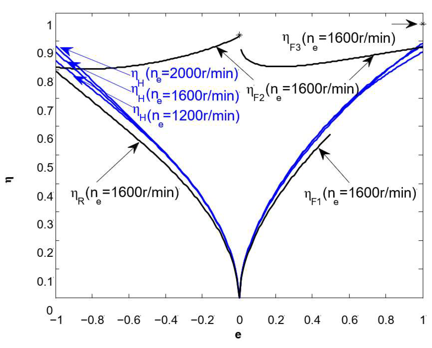
The efficiency characteristic shows that the hydrostatic system possesses preferable efficiency characteristics under the working conditions including larger displacement, higher speed, and medium pressure. Although the hydrostatic transmission efficiency is relatively low, it can realize flexible operation. The mechanical transmission efficiency is relatively high, so it demands much of road conditions, and the hydro-mechanical composite transmission can realize efficiency improvement easily in the scope of higher speed and the whole displacement ratio.

5. Patents

A hydro-mechanical composite transmission device was designed (Patent number: ZL201410337988.0).

Supplementary Materials

The following supporting information can be downloaded at: https://www.mdpi.com/article/10.3390/en16196989/s1.

Author Contributions

Conceptualization, L.C. and Y.C.; methodology, Z.Z.; software, Q.Z.; validation, Z.Z., Q.Z. and X.T.; formal analysis, Z.Z.; investigation, Z.Z.; resources, Z.Z.; data curation, Q.Z.; writing—original draft preparation, Q.Z.; writing—review and editing, Z.Z.; visualization, L.C.; supervision, Y.C.; project administration, X.T.; funding acquisition, Z.Z. All authors have read and agreed to the published version of the manuscript.

Funding

This research was funded by the Open Foundation of the State Key Laboratory of Mechanical Transmission (SKLMT-MSKFKT-202205), the Open Foundation of the State Key Laboratory of Fluid Power and Mechatronic Systems (GZKF-202214), the China Postdoctoral Science Foundation(2023M731370), the National Natural Science Foundation of China (52272435,52225212, U20A20333, U20A20331, 51875255), and the Key Research and Development Program of Jiangsu Province (BE2020083-3, BE2019010-2).

Data Availability Statement

Date is contained within the supplementary material. The date presented in this study are available in supplementary material.

Conflicts of Interest

No conflict of interest exit in the submission of this manuscript, and this manuscript is approved by all authors for publication.

Nomenclature

F x total resistance of vehicle operating system ( N )
F f rolling resistance ( N )
F w air resistance ( N )
F i slope resistance ( N )
F j acceleration resistance ( N )
F t m a x maximum tangential tractive force ( N )
G vehicle gravity ( N )
f coefficient of rolling resistance
α road slope angle
F ϕ adhesive force ( N )
ϕ adhesion coefficient
i g transmission ratio of power transmission device
n e engine speed ( r / min )
n o output speed of power transmission device ( r / min )
e displacement ratio
D P pump displacement ( c m 3 / r )
D M motor displacement ( c m 3 / r )
v vehicle speed ( km / h )
r q driving wheel power radius ( m )
i 0 transmission ratio of main reducer
i L B transmission ratio of wheel-side reducer
n P pump speed ( r / min )
T e engine torque ( Nm )
T P pump torque ( Nm )
Δ p P System pressure of the pump ( bar )
η P m mechanical efficiency of the pump
i 1 i 5 transmission ratios of general gears
i g F 1 i g F 3 transmission ratios of forward ranges
i g R transmission ratio of reverse range
k characteristic parameter of planet gear
T M motor torque ( Nm )
T o output torque of power transmission device ( Nm )
Z severity of braking
t time ( s )
p L oil pressure of main circuit ( bar )
Q v flow rate of speed control valve ( L / min )
j 3 shift jerk of intermediate shaft
j 4 shift jerk of output shaft
μ hydraulic fluid kinetic viscosity ( Pa s )
C s laminar flow leakage coefficient
Δ p P m a x maximum pressure of pump system ( bar )
C v laminar flow resistance coefficient
C f mechanical resistance coefficient
η P pump efficiency
η M motor efficiency
Δ p P m a x maximum pressure of pump system ( bar )
Δ p M m a x maximum pressure of motor system ( bar )
n M motor speed ( r / min )
η H hydrostatic system efficiency
η F 1 η F 3 efficiency of forward ranges
η i 1 η i 5 efficiency of general gears
η K efficiency of planet gear
δ power loss coefficient of planet gear

References

  1. Cai, R.; Zhang, M.; Wang, J.; Jia, F. Analysis of the Influence of Clutch Drag Torque on the Efficiency of Hydro-mechanical Continuously Variable Transmission. J. Mech. Transm. 2022, 46, 63–67+94. [Google Scholar]
  2. Zhang, M.; Wang, J.; Wang, J.; Guo, Z.; Guo, F.; Xi, Z.; Xu, J. Speed changing control strategy for improving tractor fuel economy. Trans. Chin. Soc. Agric. Eng. 2020, 36, 82–89. [Google Scholar]
  3. Chung, C.-T.; Wu, C.-H.; Hung, Y.-H. Effects of Electric Circulation on the Energy Efficiency of the Power Split e-CVT Hybrid Systems. Energies 2018, 11, 2342. [Google Scholar] [CrossRef]
  4. Antonio, R.; Alarico, M. Control strategies for a powertrain with hydro-mechanical transmission. In Proceedings of the 73rd Conference of the Italian Thermal Machines Engineering Association, Pisa, Italy, 12–14 September 2018; Volume 148, pp. 978–985. [Google Scholar]
  5. Zhang, G.; Wang, K.; Xiao, M.; Zhou, M. HMCVT Steady State Transmission Efficiency Based on HST-EGT Torque Ratio. Trans. Chin. Soc. Agric. Mach. 2021, 52 (Suppl. S1), 533–541. [Google Scholar]
  6. Li, J.; Zhao, Y.; Zhai, Z.; Han, B.; Du, Y.; Wang, L.; Zhu, Z. Research on Design and Analysis Method of the Double Planetary HMCVT Based on High Efficiency Transmission. Agriculture 2022, 12, 1958. [Google Scholar] [CrossRef]
  7. Zhu, Z.; Wang, D.; Sun, X.; Zeng, L.; Cai, Y.; Chen, L. Configuration analysis of hydro-mechanical composite transmission devices. J. Jilin Univ. (Eng. Technol. Ed.) 2022, 52, 2265–2277. [Google Scholar]
  8. Cao, J.; Peng, J.; He, H. Modeling and Simulation Research on Power-split Hybrid Electric Vehicle. Energy Procedia 2016, 104, 354–359. [Google Scholar] [CrossRef]
  9. Zhu, Z. Optimization Research on the Performance of Hydro-Mechanical Continuously Variable Transmission. Ph.D. Thesis, Jiangsu University, Zhenjiang, China, 2016. [Google Scholar]
  10. Shamshirband, S.; Petkovic, D.; Amini, A.; Anuar, N.B.; Nikolic, V.; Cojbasic, Z.; Mat Kiah, M.L.; Gani, A. Support vector regression methodology for wind turbine reaction torque prediction with power-split hydrostatic continuous variable transmission. Energy 2014, 67, 623–630. [Google Scholar] [CrossRef]
  11. Rossetti, A.; Macor, A.; Benato, A. Impact of control strategies on the emissions in a city bus equipped with power-split transmission. Transp. Res. Part D 2017, 50, 357–371. [Google Scholar] [CrossRef]
  12. Xiang, Y.; Li, R.; Brach, C.; Liu, X.; Geimer, M. A Novel Algorithm for Hydrostatic-Mechanical Mobile Machines with a Dual-Clutch Transmission. Energies 2022, 15, 2095. [Google Scholar] [CrossRef]
  13. Zhu, Z.; Gao, X.; Pan, D. Hydro-Mechanical Double Power-Flow Composite Transmission Gearbox with Single Planetary Confluence Mechanism. China Patent CN201410337988.0, 16 July 2014. [Google Scholar]
  14. Abdollahi, E.; Wang, H.; Lahdelma, R. An optimization method for multi-area combined heat and power production with power transmission network. Appl. Energy 2016, 168, 248–256. [Google Scholar] [CrossRef]
  15. Wang, C.; Zhao, Z.; Zhang, T.; Li, M. Mode transition coordinated control for a compound power-split hybrid car. Mech. Syst. Signal Process. 2017, 87, 192–205. [Google Scholar] [CrossRef]
  16. Janulevičius, A.; Giedra, K. Analysis of main dynamic parameters of split power transmission. Transport 2008, 23, 112–118. [Google Scholar] [CrossRef]
  17. Li, J.; Hu, Q. Power Analysis and Efficiency Calculation of the Complex and Closed Planetary Gears Transmission. Energy Procedia 2016, 100, 423–433. [Google Scholar]
  18. Pennestrì, E.; Mariti, L.; Valentini, P.P.; Mucino, V.H. Efficiency evaluation of gearboxes for parallel hybrid vehicles: Theory and applications. Mech. Mach. Theory 2012, 49, 157–176. [Google Scholar] [CrossRef]
  19. Montazeri-Gh, M.; Mahmoodi-k, M. Development a new power management strategy for power split hybrid electric vehicles. Transp. Res. Part D 2015, 37, 79–96. [Google Scholar] [CrossRef]
  20. Zeng, X.; Yang, N.; Wang, J.; Dafeng, S.; Nong, Z.; Mingli, S.; Jianxin, L. Predictive-model-based dynamic coordination control strategy for power-split hybrid electric bus. Mech. Syst. Signal Process. 2015, 60–61, 785–798. [Google Scholar] [CrossRef]
  21. Liu, Y.; Qin, D.; Jiang, H.; Zhang, Y. Shift control strategy and experimental validation for dry dual clutch transmissions. Mech. Mach. Theory 2014, 75, 41–53. [Google Scholar] [CrossRef]
  22. Oh, J.J.; Choi, S.B.; Kim, J. Driveline modeling and estimation of individual clutch torque during gear shifts for dual clutch transmission. Mechatronics 2014, 24, 449–463. [Google Scholar] [CrossRef]
  23. Cao, F. Study on Hydro-Mechanic Differential Turning Performance Analysis and parameters Matching of Tracked Vehicle. Ph.D. Thesis, Xi’an University of Technology, Xi’an, China, 2009. [Google Scholar]
  24. Zhang, L.; Yang, S.; Li, X.; Han, B.; Pang, Y. Research on kinematic characteristics of two-stage hydro-mechanical continuously variable transmission mechanism. Chin. J. Eng. Des. 2021, 28, 268–277. [Google Scholar]
  25. Wang, G.; Zhu, S.; Shi, L.; Ni, X.; Ruan, W.; Ouyang, D. Simulation and experiment on efficiency characteristics of hydraulic mechanical continuously variable transmission for tractor. Trans. Chin. Soc. Agric. Eng. 2013, 29, 42–48. [Google Scholar]
  26. Zhu, Z.; Gao, X.; Pan, D.; Xia, C.; Shang, G.; Han, J. Efficiency Test Bench of Electro-Hydraulic Proportional Pump Motor Control System. China Patent CN201410405732.9, 18 August 2014. [Google Scholar]
  27. Zhu, Z.; Gao, X.; Pan, D.; Xia, C.; Shang, G.; Han, J. Test Bench of Hydro-Mechanical Continuously Variable Transmission. China Patent CN201410330354.2, 11 July 2014. [Google Scholar]
  28. Do, H.T.; Park, H.G.; Ahn, K.K. Application of an adaptive fuzzy sliding mode controller in velocity control of a secondary controlled hydrostatic transmission system. Mechatronics 2014, 24, 1157–1165. [Google Scholar] [CrossRef]
  29. Macor, A.; Rossetti, A. Optimization of hydro-mechanical power split transmissions. Mech. Mach. Theory 2011, 46, 1901–1919. [Google Scholar] [CrossRef]
  30. Yang, Y.; Hu, X.; Pei, H. Comparison of power-split and parallel hybrid powertrain architectures with a single electric machine: Dynamic programming approach. Appl. Energy 2016, 168, 683–690. [Google Scholar] [CrossRef]
  31. Ivanov, K.; Gonzalez-Cruz, C.A.; Ceccarelli, M.; Ozhiken, A.K.; Cafolla, D. Design and Experiences of a Planetary Gear Box for Adaptive Drives. In EuCoMeS 2018. Mechanisms and Machine Science; Corves, B., Wenger, P., Hüsing, M., Eds.; Springer: Cham, Switzerland, 2019; Volume 59. [Google Scholar]
Figure 1. Design scheme showing the multipurpose power transmission device.
Energies 16 06989 g001
Figure 2. Relationship curves between the transmission ratio and the displacement ratio.
Energies 16 06989 g002
Figure 3. Intermediate shaft and output shaft speed curves of the power transmission device.
Energies 16 06989 g003
Figure 4. Intermediate shaft and output shaft shift jerks of the power transmission device.
Energies 16 06989 g004
Figure 5. Comparison of the best and worst working condition curves of the power transmission device based on the orthogonal analysis method. (a) Comparison of the curves for output speeds and (b) comparison of the curves for output shaft shift jerks.
Energies 16 06989 g005
Figure 6. Speed regulation characteristic curves of the multifunctional power transmission device.
Energies 16 06989 g006
Figure 7. Efficiency curves of the multipurpose power transmission device.
Energies 16 06989 g007
Figure 8. Efficiency test curves of the multipurpose power transmission device.
Energies 16 06989 g008
Table 1. Component (clutches and brakes) status of the multipurpose power transmission device.
RangeC1C2C3C4C5B1B2
F1
F2
F3
R
Note: “●” represents the engaging status of clutches and brakes. F1: forward first gear (hydrostatic drive), F2: forward second gear (hydro-mechanical drive), F3: forward third gear (mechanical drive), R: reverse gear (hydrostatic drive).
Table 2. Test data.
Table 2. Test data.
Ground f ϕ F t m a x F ϕ
Clay soil0.02~0.050.67~0.720.36~0.390.67~0.72
Sandy loam 0.03~0.060.48~0.520.37~0.400.48~0.52
Grass0.07~0.080.38~0.430.41~0.420.38~0.43
Farmland0.10~0.120.68~0.740.44~0.460.68~0.74
Table 3. Displacement ratios of the hydrostatic system and ranges at different time periods.
t0–55–1010–1515–2020–2525–30
e00.50.51.01.01.0
RangeF1F1F2F2F3F3
Table 4. The friction work of each component of the multifunctional power transmission device.
Shift ComponentsC1 (J)C2 (J)C4 (J)C5 (J)B1 (J)B2 (J)
Condition 1521684,53155,332857311407678
Condition 2536645,10652,610501110346346
Condition 3609544,70957,042308210111773
Disclaimer/Publisher’s Note: The statements, opinions and data contained in all publications are solely those of the individual author(s) and contributor(s) and not of MDPI and/or the editor(s). MDPI and/or the editor(s) disclaim responsibility for any injury to people or property resulting from any ideas, methods, instructions or products referred to in the content.

