Article

Three-Port Bi-Directional DC–DC Converter with Solar PV System Fed BLDC Motor Drive Using FPGA

by
Arun Kumar Udayakumar
1,*,
Raghavendra Rajan Vijaya Raghavan
2,
Mohamad Abou Houran
3,
Rajvikram Madurai Elavarasan
4,
Anushkannan Nedumaran Kalavathy
5 and
Eklas Hossain
6,*
1
Department of Electrical and Electronics Engineering, SRM Institute of Science and Technology, Ramapuram Campus, Chennai 600089, Tamilnadu, India
2
Automotive Department, Harman Connected Services India Pvt. Ltd., Bengaluru 560095, Karnataka, India
3
School of Electrical Engineering, Xi’an Jiaotong University, Xi’an 710049, China
4
School of Information Technology and Electrical Engineering, The University of Queensland, St Lucia, QLD 4072, Australia
5
Department of Electronics and Communication Engineering, Kathir College of Engineering, Coimbatore 641062, Tamilnadu, India
6
Department of Electrical and Computer Engineering, Boise State University, Boise, ID 83725, USA
*
Authors to whom correspondence should be addressed.
Energies 2023, 16(2), 624; https://doi.org/10.3390/en16020624
Submission received: 9 December 2022 / Revised: 22 December 2022 / Accepted: 29 December 2022 / Published: 4 January 2023

Abstract

:
The increased need for renewable energy systems to generate power, store energy, and connect energy storage devices with applications has become a major challenge. Energy storage using batteries is most appropriate for energy sources like solar, wind, etc. A non-isolated three-port DC–DC-converter energy conversion unit is implemented feeding the brushless DCmotor drive. In this paper, a non-isolated three-port converter is designed and simulated for battery energy storage, interfaced with an output drive. Based on the requirements, the power extracted from the solar panel during the daytime is used to charge the batteries through the three-port converter. The proposed three-port converter is analyzed in terms of operating principles and power flow. An FPGA-based NI LabView PXI with SbRio interface is used to develop the suggested approach’s control hardware, and prototype model results are obtained to test the proposed three-port converter control system’s effectiveness and practicality. The overall efficiency of the converter’s output improves as a result. The success rate is 96.5 percent while charging an ESS, 98.1 percent when discharging an ESS, and 95.7 percent overall.

1. Introduction

While renewable energy is good for the planet and produces no pollution, its steady yet fluctuating DC voltage is a drawback. When it comes to solar panels, for instance, the sun’s position in the sky and the time of day affect not just the amount of energy harvested, but also the voltage and current that is ultimately transmitted. Since wind speed cannot be controlled, the generator’s output voltage is not high enough to power an inverter directly, making an AC voltage converter or other load necessary. As part of this research, we designed a non-isolated three-port converter to connect a battery to an output drive. During the daytime, energy is collected by solar panels and sent to the three-port converter, which then charges the batteries. An analysis of the proposed TPC converter’s working principles and power flow is also provided.
An efficient, compact, and cost-effective bidirectional step-up/step-down converter may be built with the use of shared switches. A three-port circuit is used to connect the regenerative energy system to an energy storage battery. High-voltage gain boost-buck three-port bidirectional conversion circuits and three-port bidirectional single storage inductor DC–DC converter circuits are examples of popularly used non-isolated three-port bidirectional DC–DC converters. These bidirectional DC–DC converters do not feature isolation, but they are cheap, easy to build, and have few internal components. Due to the reduced number of energy storage components, however, increasing the voltage gain of the circuit is challenging.
Various multi-port converters have been investigated for electric vehicles, energy storage (ES), and photovoltaic (PV) applications [1,2]. The multi-port converters require only a few energy conversion stages. Due to this power density and energy conversion, efficiency is high when compared to conventional converters [3]. This advantage made the storage elements and photovoltaic units be accommodated with this and this unit is integrated with micro grids (MGs) [4]. The ES and PV can be integrated into MGs, with the help of a three-port converter (TPC), instead of a multi-port converter. There are two classes of TPC topology; they are isolated [5], and non-isolated [6]. Isolated topologies are again classified as partially isolated TPCs, and fully isolated TPCs [7].
Three-ports are built utilizing a multi-winding transformer in fully isolated TPCs. Each of the three ports is completely isolated from the others. Ports are designed to have three full and half bridges, or a series of resonant designs in contact with them [8]. A third port in a partly-isolated TPC is disconnected from the other two ports. A partly-isolated TPC is created by merging two networks that are both isolated and non-isolated.
Isolated TPCs are required for applications of higher power than non-isolated applications. Non-isolated TPCs may offer high effectiveness, energy output, and reduction in costs in low-power applications, by reducing the number of transistors in the circuit [9]. Recently, many non-isolated TPCs have been introduced. Paper [10] proposes building a non-isolated TPC by sandwiching a general cell between standard buck, boost, and buck-boost converters. Because this TPC only has two MOSFETs and one inductor, it is smaller and less expensive. Minimal power, stand-alone renewable energy systems typically use TPCs.
Conventional step-down, step-up and buck-boost converters are combined [11] to build a TPC. This single-switch TPC allows for regulation of both switching frequency and duty cycle. Because of the lack of a decoupled control approach, the usefulness and efficiency of this TPC are severely constrained. Dual input or output converters can be given with additional power flow path to form a TPC family [12]. It is very small in size and has high integration. During the charging and discharging operation, the battery voltage is adjusted to be as near as possible to the PV voltage. PV voltage redesign is a time-consuming and labor-intensive undertaking. Paper [13] proposes a three-port high-voltage converter with higher gain. The current flow is continuous in the port with low voltage. There are seven semiconductor devices, which makes the process of system design a complicated one. Using shared switches allows for a bidirectional step-up/step-down converter to be created, which reduces the amount of components, cost, and size of the converter. A three-port circuit is used to connect the regenerative energy system to an energy storage battery [14,15,16,17]. Two-inductor bidirectional buck converter and two inductor boost converters are combined to make a continuous current flow in all the ports of a TPC [14,15,16,17].
The power density of this TPC can be improved and optimized by using the magnetic integration technique proposed in [18,19,20,21,22]. High-voltage gain non-isolated TPCs are proposed in [23,24,25,26,27,28], and they are very complex in structure. An important addition of this research is the single-stage power conversion that occurs between the load port and PV, or between the load port and battery, depending on the configuration [29]. Power density is also improved by sharing the passive power devices in various power flow modes. The efficiency can also be improved by decreasing the conversion gain by connecting PV [30] in series with battery during the discharging domain, and making a parallel connection between them in the charging domain.
In recent years, the global energy calamity has been acknowledged as the requirement to enhance more energy-efficient systems, if possible, whilst beingclean and non-exhaustible. The strong lessening of conservative energy sources couldcreate future generations of researchers to search for sources of renewable energy. Sources of renewable energy can be wind energy, fuel cell, and solar PV systems. In the power industry, the solar PV system has attained extensive concentration. Solar energy can be an ideal kind of renewable energy source, as it has zero running costs, is environment responsive, and has simple deployability [31,32,33]. The output of direct current (DC) in a solar PV system is generated, and it is effortlessly interfaced with the DC microgrid and Energy Storage System.
Numerous researchers have exploited the solar PV system for renewable energy. In [31], a modular hybrid renewable energy system was presented, in which biogas and solar PV had been combined for several dairy cattle barns located in Turkey. The grid-connected scheme that contains biomass and PV was more sufficient, compared to the stand-alone biomass scheme, in terms of energy cost, net present cost, and annual worth. The grid combination of solar PV systems was increased with two major motivations: energy cost reduction, and greenhouse gas emission reduction. Conversely, the solar PV-generated power’s irregular nature affects the grid constant voltage. As a result, a structure was proposed in [32] to provide the constant voltage examination, because of suspicions related to the power generation and load demand of the PV system, with the help of the Monte Carlo simulation. For the incorporation of solar PV and ESS, an incorporated conception was presented in [33] for the diffusion of links of AC grid and high-voltage direct current (HVDC), known as multi-port autonomous reconfigurable solar (MARS) power plant. For super-efficient electrical purposes, grid-tied and off-grid solar PV systems are designed and optimized [34]. In the optimization process, hourly calculations have been exploited for the daily and yearly performance estimation and the renewable energy systems’ cost evaluation. In [35], an event-driven predictive approach has been presented for optimization of real-time volt/volt-ampere reactive (VAR), by applying a local two-level adaptive volt/VAR droop-based control algorithm.
In a single photovoltaic system (PVS), the voltage level can be very low, and the source may not be rigid; consequently, a converter interface might be needed. Therefore, buck, boost, and buck-boost converters were typically exploited for PVS [36,37,38,39,40,41,42,43]. For MPPT control, buck converters have decreased the voltage level and are appropriate at the smallest number of modifications in temperature or irradiance. The output voltage was increased, and the input was increased twice by the boost converter. From the concatenation of buck and boost converters, the buck-boost converter has been derived. For higher loading, the boost converter might not be appropriate, since the system can attain maximum power point at top conditions. A DC–DC converter has been required and worked with MPPT to the boundary of PV Source and load [43]. Better harvest of solar power can be given through MPPT. Thus, numerous researchers have developed some MPPT methods. The MPPT’s effectiveness is calculated according to the converter’s input impedance in various atmospheric situations. In the solar PV system, Incremental Conductance (IC), Perturb and Observe (P&O), and Hill Climbing MPPT algorithms have been exploited for harvesting power enhancement [44,45,46,47,48]. In [49,50], an improved P&O algorithm and tracker of solar has been presented for the separate solar PV scheme. An improved and modified IC algorithm was proposed for PV system modeling for quick modifications of irradiance. A modified hill climbing MPPT algorithm was presented in [51], with decreased fluctuation of steady-state and enhanced tracking effectiveness.
In general, a PV panel can produce the DC, other than most frequent household appliances, such as fans; it can also use single-phase induction motors, and thus, a DC to AC converter is needed to function, hence conversion loss may have been introduced [51]. This kind of difficulty could not be exterminated through the replacement of an AC induction motor with a DC motor. However, a DC motor may be limited by high maintenance cost, small rpm application, and high electromagnetic (EM) noise [52]. A BLDC is exploited as an appropriate alternate, since it contains an enhanced power-to-weight ratio, compared to a conservative induction motor, with the added benefit of openly being capable of power run of DC [53]. However, for speed control of BLDC drive, the extra current sensors and control strategy can enhance the difficulty and cost. A two-port bidirectional-based application, such as DC microgrid and regenerative braking, has been analyzed in [54]. To achieve high-power density and high efficiency in combined OBC and APM for EV applications, [55,56] proposes a novel, isolated, three-port, bidirectional DC–DC converter architecture and its control. In [55], a unique three-port high step-up/step-down bidirectional DC–DC converter with a linked inductor is presented for photovoltaic (PV) systems, in order to boost the system’s overall efficiency and decrease switch loss.
In this work, we have developed a non-isolated three-port converter for coupling a battery to an output motor. When the sun provides the energy, the TPC converter takes the energy harvested from the solar panels and uses it to charge the batteries. The operation principles and power flow of the proposed three-port converter are also examined. RCP FPGA-based systems allow for reconfiguration, co-simulation, HIL, automated VHDL code development, and system expansion. This is done using the XSG, an FPGA-programming Simulink plug-in design tool from Xilinx. High-level Simulink abstractions are turned into lower-level and executable VHDL code through the bit stream. The proposed system shown in Figure 1 has the following advantages:
  • The proposed converter is utilized for simultaneous power management of a PV system with a battery;
  • The charge and discharge controller provides control to the integrated battery to either absorb the additional power supplied during daytime or supply the power during absence of sun;
  • The proposed system can be highly employed to low-power household applications, such as air conditioners.

2. Mathematical Modeling of the Proposed System
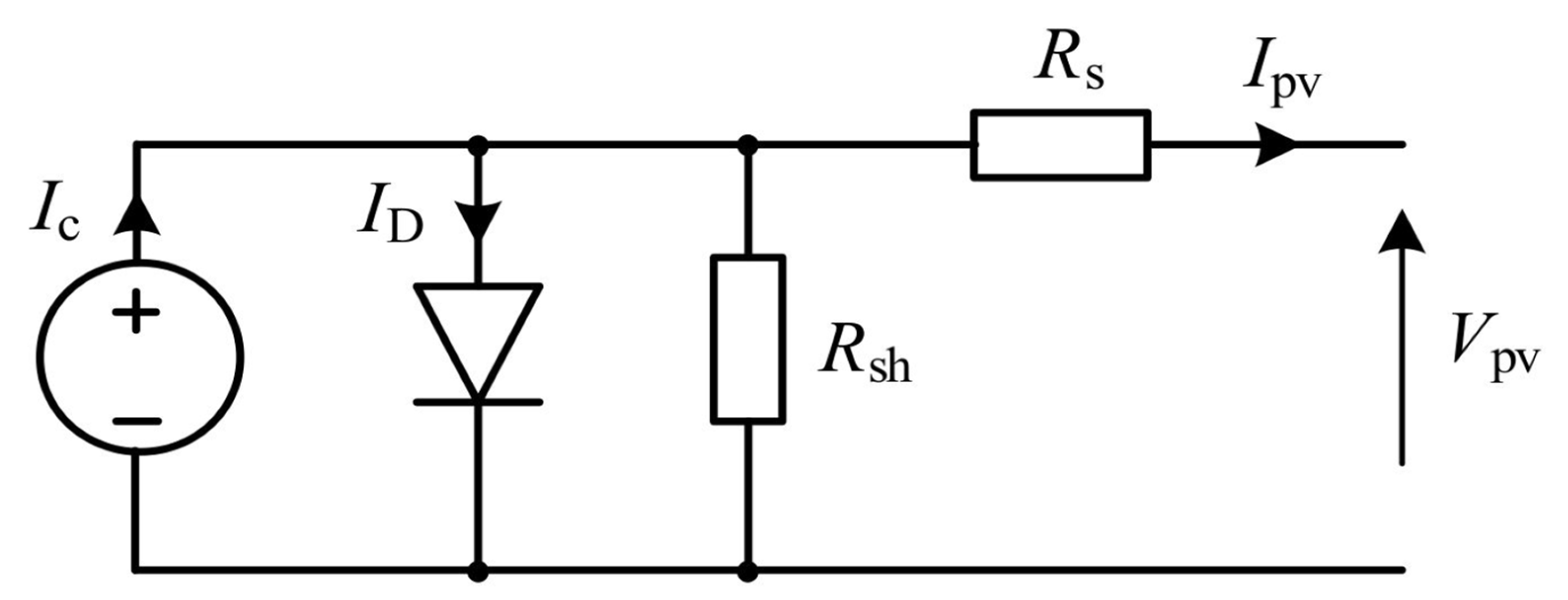
2.1. PV Modeling

A PV module’s mathematical model could be attained from a PV solar cell’s equivalent circuit (Figure 2). I c can be the photocurrent that is produced through the PV cell, according to the temperature of the cell and irradiation of solar irradiation, and R s and R sh represent the series and push interior resistances of the PV cell.
The nonlinear V–I feature of the PV solar cell can be evaluated through Equation (1):
I PV = I c I 0 exp q V PV + R s I PV kT 1 V PV + R S I PV R sh
In the above Equation (1), electron charge is symbolized by q , I 0 represents the diode’s overturn diffusion current, the Boltzmann steady state can be denoted by the k , and T denotes the working cell temperature in Kelvin.
In a module of PV, an assortment of a dozen PV solar cells has been linked in series to obtain more voltage and power, because the voltage of a PV solar cell has to be about 0.5 V. Therefore, some PV modules have been linked in series already to form a string of PV. A few of these strings of PV might be linked in parallel.

2.2. Modeling of BLDC Motor Drive

In general, a BLDC motor contains three-phase stator windings that link with a star link. In the rotor of the BLDE motor, stable magnets are exploited. A three-phase BLDC motor’s winding has been modeled as a series circuit that contains an inductance L, resistance R, and a source of speed dependent voltage that can be called the back voltages of EMF in the rotor magnet [26]. Induced current in the rotor iron and losses of stray in the stator harmonics areas can be abandoned during the BLDC motor designing process [27]. In the BLDC motor, individual and mutual inductances have been measured as constant.
The BLDC motor’s mathematical model will be acquired using the following Equations (2)–(12):
V a = RI a + d dt F a + E a
V b = RI b + d dt F b + E b
  V c = RI c + d dt F c + E c
where R indicates the stator winding’s resistance, I a , I b , I c denote the current of the three phase stator, V a , V b , V c can be the voltage of three stator, three-phase back EMF is denoted by E a , E b , E c , and F a , F b , F c represents the flux linkage of the stator. The flux linkage of the stator will be calculated using the following Equations (5)–(7):
F a = L aa I a + L ab I b + L ac I c
  F b = L ba I a + L bb I b + L bc I c
F c = L ca I a + L cb I b + L cc I c
In the above Equations (5)–(7), L ab , L ac , L bc , L cb , L ba represents the joint inductance between the winding of stator, and L aa , L bb , L cc denotes the stator self-inductance, given in Equation (8):
V a V b V c = R 0 0 0 R 0 0 0 R I a I b I c + L aa L ab L ac L ba L bb L bc L ca L cb L cc d dt I a I b I c + E a E b E c
Equation (8) will be written as:
V a V b V c = R 1 0 0 0 1 0 0 0 1 I a I b I c + L M M M L M M M L d dt I a I b I c + E a E b E c
Equation (9) could be rewritten as:
V a V b V c = R 1 0 0 0 1 0 0 0 1 I a I b I c + L M 0 0 0 L M 0 0 0 L M d dt I a I b I c + E a E b E c
where stator winding’s self-inductance can be denoted by the L, and stator winding’s mutual inductance is represented by M. The straight connection between exploited source voltage to induced back EMF (E) and phase terminal V   might be resultant for steady mutual inductance and self-inductance approximate air gap, given by Equation (11).
E α V
Only two phases of conduct are employed at a time whereas the third phase floats in running mode, as per the operational code of the BLDC motor; this decreases Equations (10)–(12) and is given by:
V a V b = R 1 0 0 1 I a I b + L M 0 0 L M d dt I a I b + E a E b

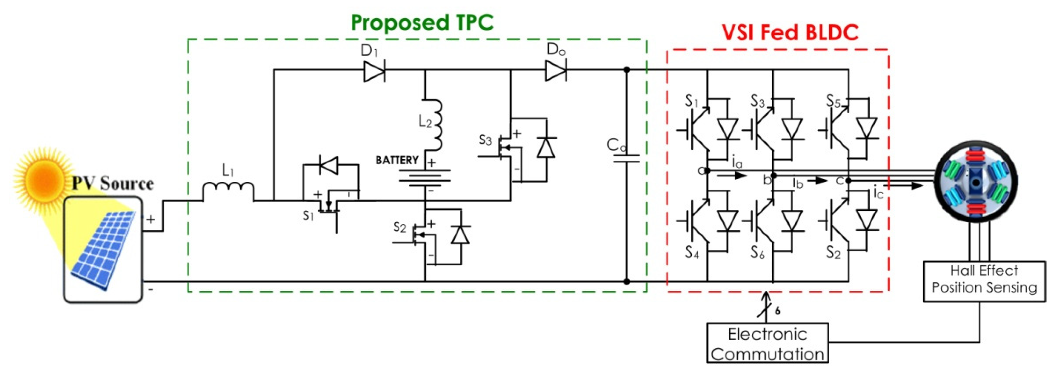
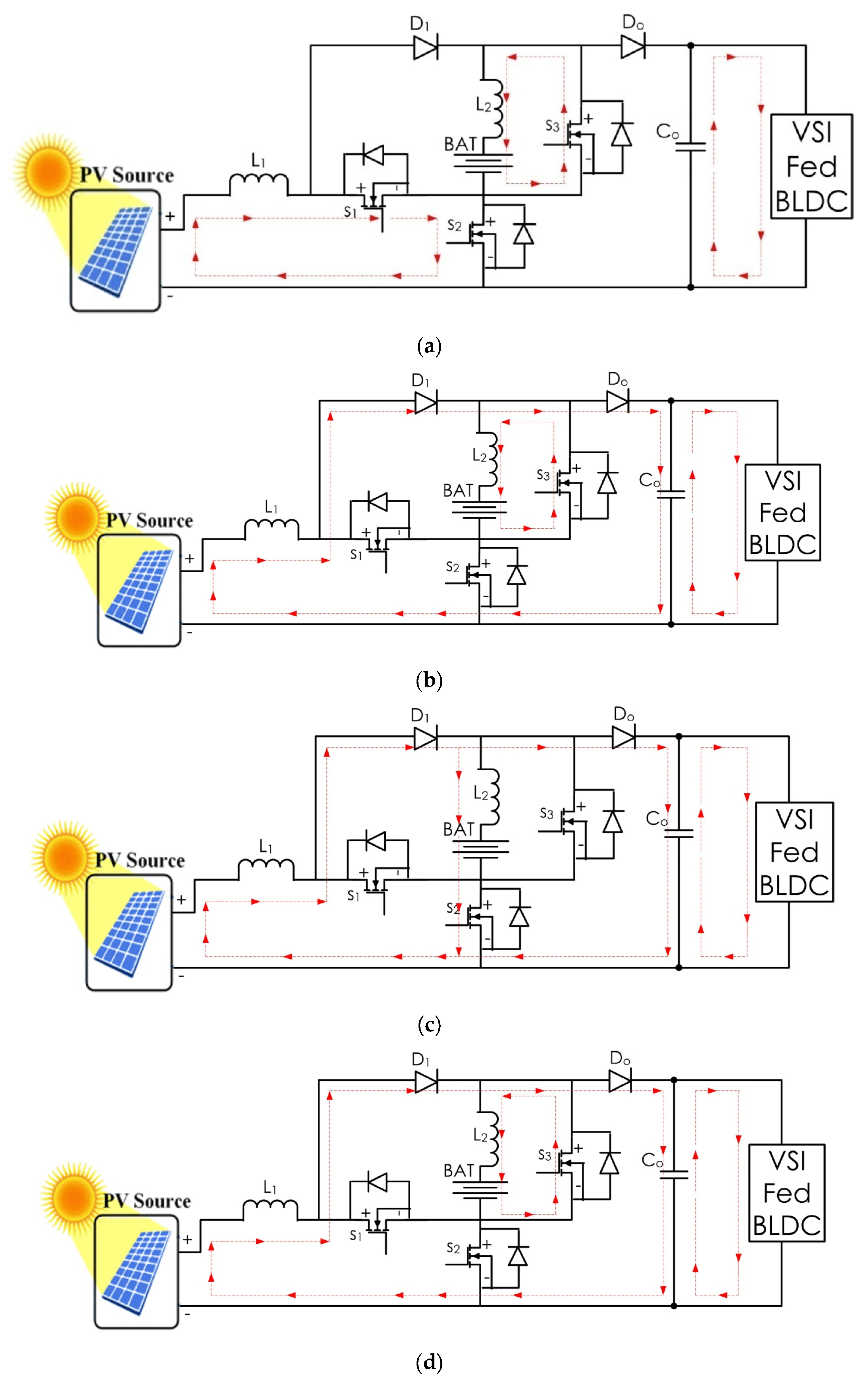
3. Design of Converter and Operating Principles

The voltage extension cell and switching circuit built around an inductor serve as the converter’s foundation, as seen in Figure 1. For each input, there are two distinct phases in the proposed converter, which has three operating modes: i. Power transfer between input and output independently; ii. Power transfer from input to output occurs at the same time; iii. Transmission of energy from a power generator to a load, which is also used for ESS charging. The energy from all the sources is controlled by using two different phases. The voltage gain may be increased by using two voltage extension cells in series and parallel. By using the same components in many working modes, the suggested converter may use fewer parts.
The ESS charging and discharging state defines the operation of the proposed converter. During discharging, switch S2 body diode SD2 is always "OFF”. Energy is transferred from one phase to the next independently. S1 and S2 are the main switches in the converter, whereas diodes D1 and D0 will conduct. The filter capacitor and inductive element are given by C0, L1 and L2. In charging mode, the switch S3 body diode SD3 is always “OFF”. PV phases transmit the energy from the inputs to the output and batteries. S1 and S3 are the converter’s primary switches. Diodes D1, D0 will be in conduction. The filter capacitor and inductive element are given by C0, L1, and L2.

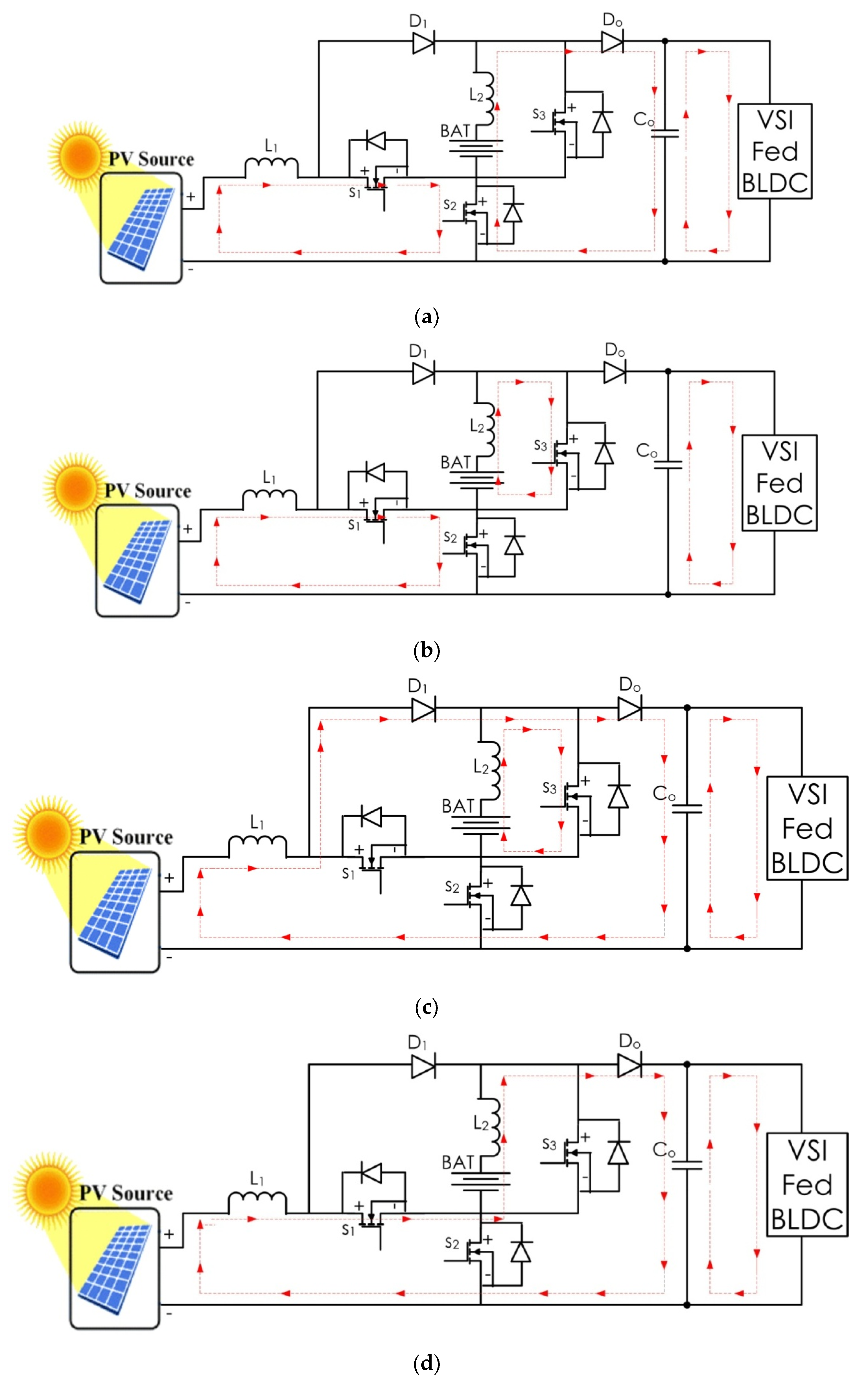
3.1. ESS Discharging Domain

In a single switching cycle, the switch may operate in one of four modes. The suggested converter’s waveforms and comparable circuit are shown in Figure 3 and Figure 4:
Mode I (a): In this mode, switches (S2) will be in the “ON” position, and switches (S3) will be in the “OFF” position. Diode (D1) is reverse biased. Figure 4a shows the proposed converter’s equivalent circuit. From the PV source, input side inductor (L2) starts charging, and current (IL1) increases. The inductor (L2) of ESS and battery are starting to get discharged via (SD2) body diode of switch (S2) to output capacitor (C0). Current (IL2) is decreasing, and output capacitor (C0) is started to get discharged to load.
Mode I (b): In this mode, switch (S2 and S3) will be in the “ON” position. Diodes (D1) (SD2) and (SD3) are reversely biased. Figure 4b illustrates the equivalent circuit of the suggested architecture. From the PV source, input side inductor (L1) starts charging, and current (IL1) increases. The inductor (L2) of ESS and battery are starting to get charged via (SD2) body diode of switch (S3) to output capacitor (C0). Current (IL2) is increasing, and output capacitor (C0) is started to get discharged to load.
Mode I (c): In this mode, switches (S3) will be in the “ON” position, and switches (S2) will be in the “OFF” position. Diode D 1 is forward biased. Figure 4c shows the proposed converter’s equivalent circuit. From the PV source, input side inductor (L1) starts discharging via diode (D1) to charge the capacitor (C0).The inductor (L2) of ESS and battery are starting to get charged via switch (S3). The output capacitor (C0) is started to get discharged to load.
Mode I (d): In this mode, switch (S3) and switch (S2) will be in the “OFF” position, and switch (S2) will be in the “ON” position. Diode D 1 ,   ( SD 2 ) and ( SD 3 ) are reverse biased. Figure 4d shows the proposed converters equivalent circuit. From the PV source, input side inductor ( L 1 ) starts discharging via diode (D1) to charge the capacitor ( C 0 ). The inductor ( L 2 ) of ESS and battery are starting to get charged via switch ( S 3 ). The output capacitor ( C 0 ) is started to get discharged to load.

3.2. ESS Charging Domain

In one switching period, based on the state of the switch, there are four operational modes. The suggested converter’s waveforms and comparable circuit are shown in Figure 5 and Figure 6.
Mode II (a): In this mode, switches ( S 1 )   and   ( S 2 ) will be in the “ON” position. Diode D 1 is reverse biased. Figure 6a illustrates the suggested converter’s equivalent circuit. From the PV source, input side inductor ( L 1 ) starts charging, and current ( i L 1 ) increases. The inductor ( L 2 ) of ESS and battery are starting to get charged via ( SD 3 )   body diode of switch ( S 3 ) to output capacitor ( C 0 ) . Current ( i L 2 ) is decreasing, and output capacitor ( C 0 ) is started to get discharged to load.
Mode II (b): In this mode, switches ( S 1 )   and   S 2 will be in the “OFF” position. Diodes ( D 1 ) , ( SD 2 ) , and ( SD 3 ) are forward biased. Figure 6b illustrates the suggested converter’s equivalent circuit. From the PV source, input side inductor ( L 1 ) starts discharging, and current ( i L 1 ) increases. The inductor ( L 2 ) of ESS and battery are starting to get charged via ( SD 3 )   body diode of switch ( S 3 ) to output capacitor ( C 0 ) . Current ( i L 2 ) is decreasing, and output capacitor ( C 0 ) is started to get discharged to load.
Mode II (c): In this mode, switch ( S 2 ) will be in the “ON” position, and switch ( S 1 ) will be in the “OFF” position. Diode D 1 is forward biased. Figure 6c shows the proposed converter’s equivalent circuit. From the PV source, input side inductor ( L 1 ) starts discharging via diode ( D 1 ) to charge the capacitor ( C 0 ). The inductor ( L 2 ) of ESS and battery are starting to get charged via switch ( S 3 ). The output capacitor ( C 0 ) is started to get discharged to load.
Mode II (d): In this mode, switch ( S 2 ) and switch ( S 1 ) will be in the “OFF” position. Diode D 1 ,   ( SD 2 ) and ( SD 3 ) is forward biased. Figure 6d shows the proposed converter’s equivalent circuit. From the PV source, input side inductor ( L 1 ) starts discharging via diode ( D 1 ) to charge the capacitor ( C 0 ). The inductor ( L 2 ) of ESS and battery are starting to get charged via switch ( S 3 ). The output capacitor ( C 0 ) is started to get discharged to load.

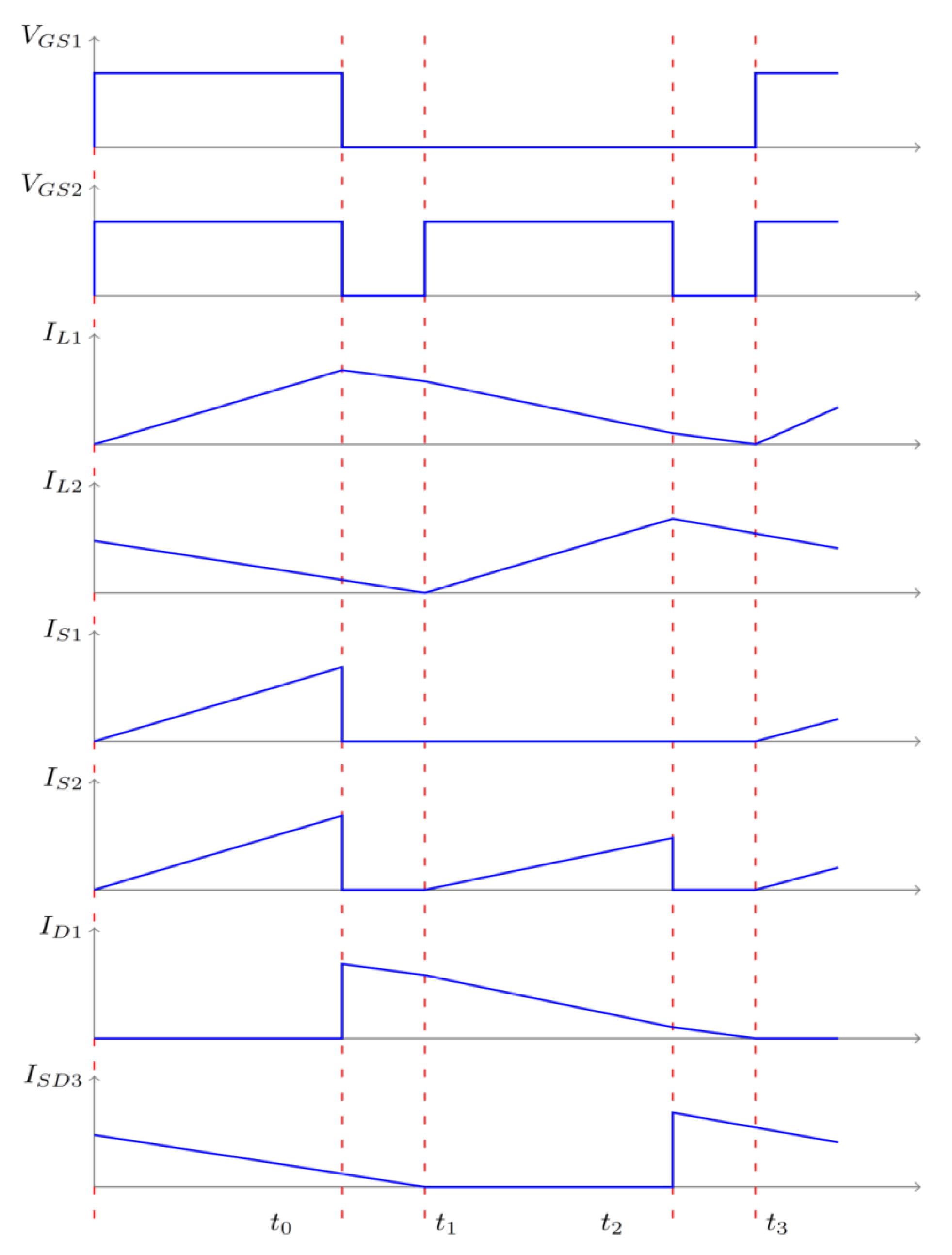
3.3. Design of Proposed Bi-Directional DC–DC Converter

In order to get the appropriate ripple effects, the values of L1 and L2 are carefully chosen. The value of inductance L1 and L2 and capacitance C0 is calculated using the formula:
L k = V k · D k f s · Δ I k
C 0 = I 0 · ( 1 D k ) f s · Δ V c s
where k = 1 and 2, Δ V cs is the voltage ripple of C0, and:
Δ I k = C k Δ V k D k · T s

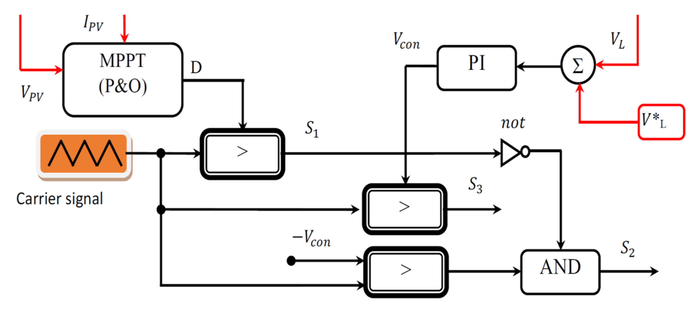
4. Proposed TPC Control

To achieve the load requirements, the converter’s load port should be regulated tightly and, to have maximum energy, the PV port must have maximum power tracking capability. In order to have battery management, the current in battery port charging must be regulated. There are two ways to control the action; one manages the current flowing via the load port, while the other manages the flow of (L2). Battery charging and discharge are both regulated by them.
Figure 7 illustrates the proposed scheme’s modulation and control methods. The output of the MPPT algorithm is represented by ‘D’. PV panel voltage and current are given by V PV and I PV . By correlating the voltage level to the reference value, the output voltage is controlled. Based on the proportion and integral gain of voltage controller (PI), the difference in voltage is amplified and is represented as V con . The triangle carrier signal is used to compare V con . Figure 7 shows the controlled state S 2 and S 3 of the battery.

Control of Brushless DC Motor Drive

For the BLDC motor drive, an electronic commutation control scheme can be employed, due to its flexibility and efficiency. Table 1 shows the electronic communication of the PWM inverter for the BLDC motor drive. The PWM inverter has been generated controllable and, therefore, the power balance might be attained through speed regulation of the BLDC motor. Electronic commutation is adopted since the suggested system is designed for low-power household applications. In case of systems where it requires high initial torque, such as automatic fuel pump applications, a sensorless approach, such as the hysteresis comparator technique shall be applied.

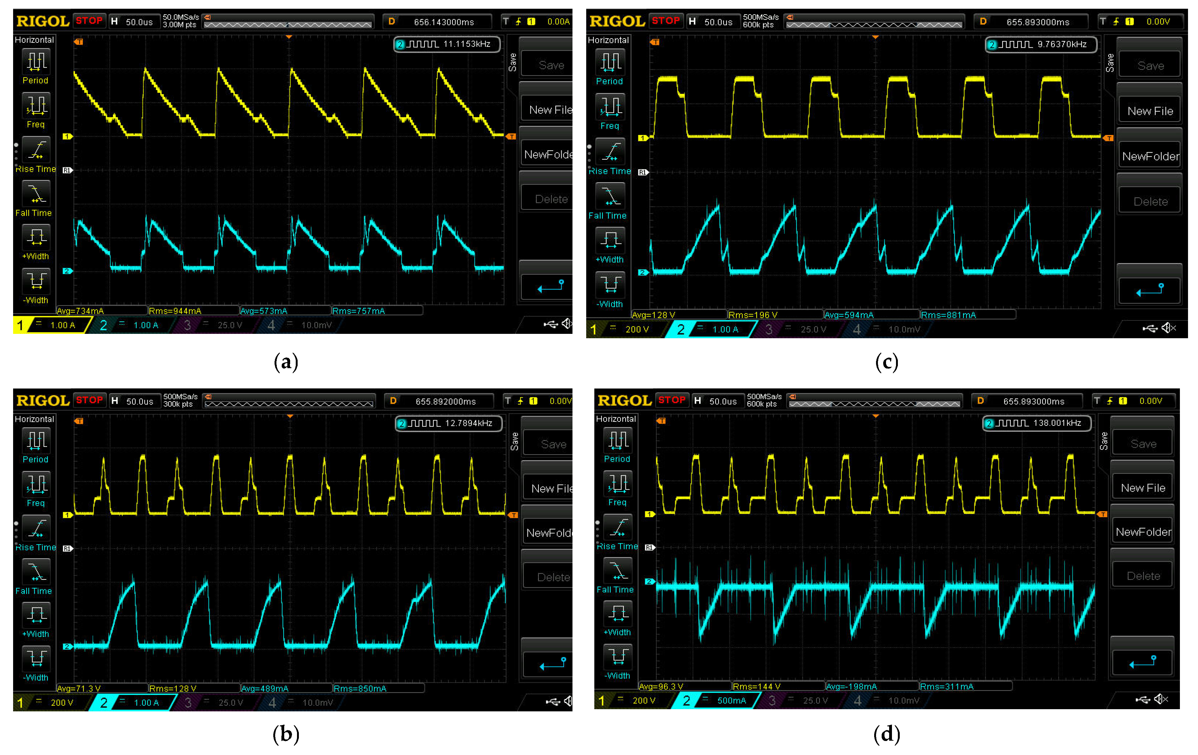
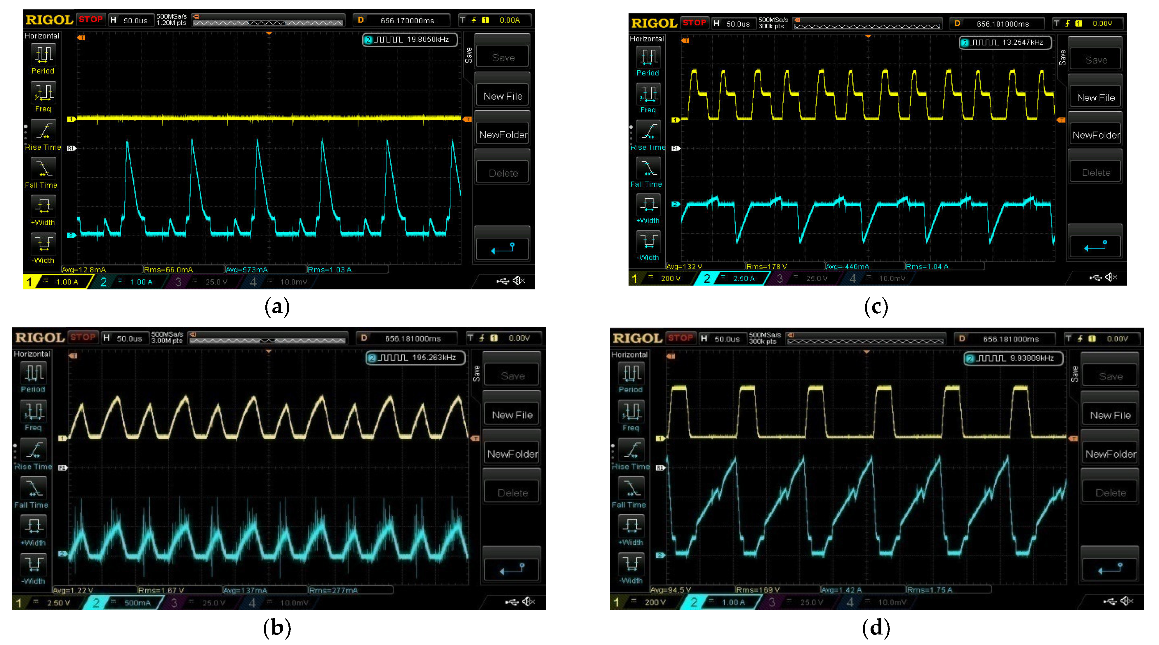
5. Experimental Results and Discussions

An FPGA-based system with a Xilinx board interface is used to implement the proposed integrated hybrid energy system control. For the implementation of real-time analogue signals, the system is programmed using a NI-PXIe 1082 chassis. Hall sensors LA 25-P and LV 20-P are used to detect the signals. The suggested converter operates in the sun domain (SD), while the distribution solar irradiation is high, and in the MBCD, when the solar irradiation is lowered to some desired value, based on domain. During the night, it performs the function of MBDD. Solar energy is an important factor in all three domains of the converter’s performance, including load voltage management and modes that are automatically changed based on power circumstances at any given time. The next sections go through the findings of the experiment. Table 2 shows specifications of converter input and output used in experimentation:
Figure 8 shows the experimental setup of the proposed system. It comprises the proposed DC–DC converter which is fed through a Solar PV system, a battery, FPGA control board, and a BLDC motor drive. The parameters of the proposed system are mentioned in Table 2, along with the values of inductors and capacitors.

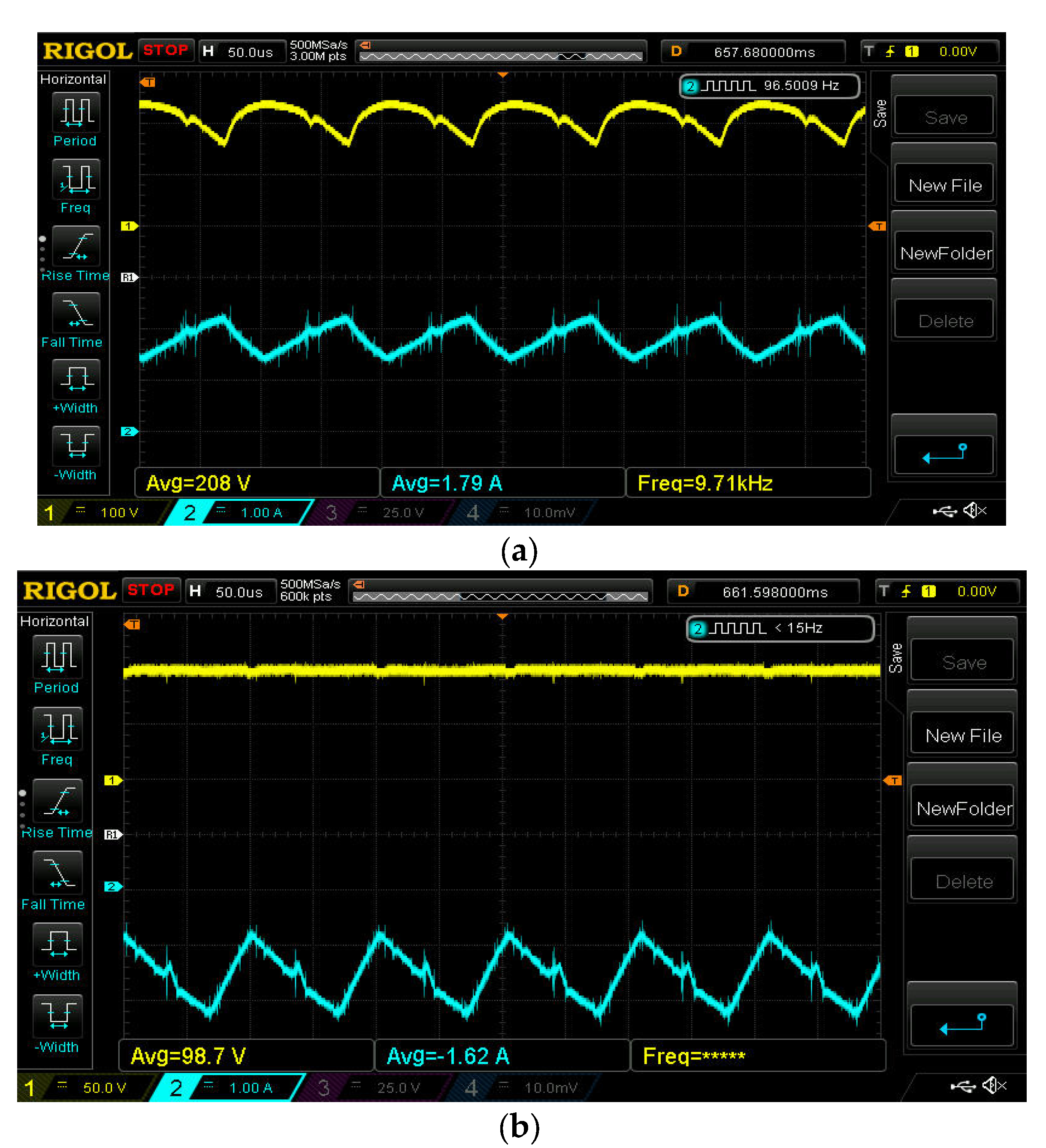
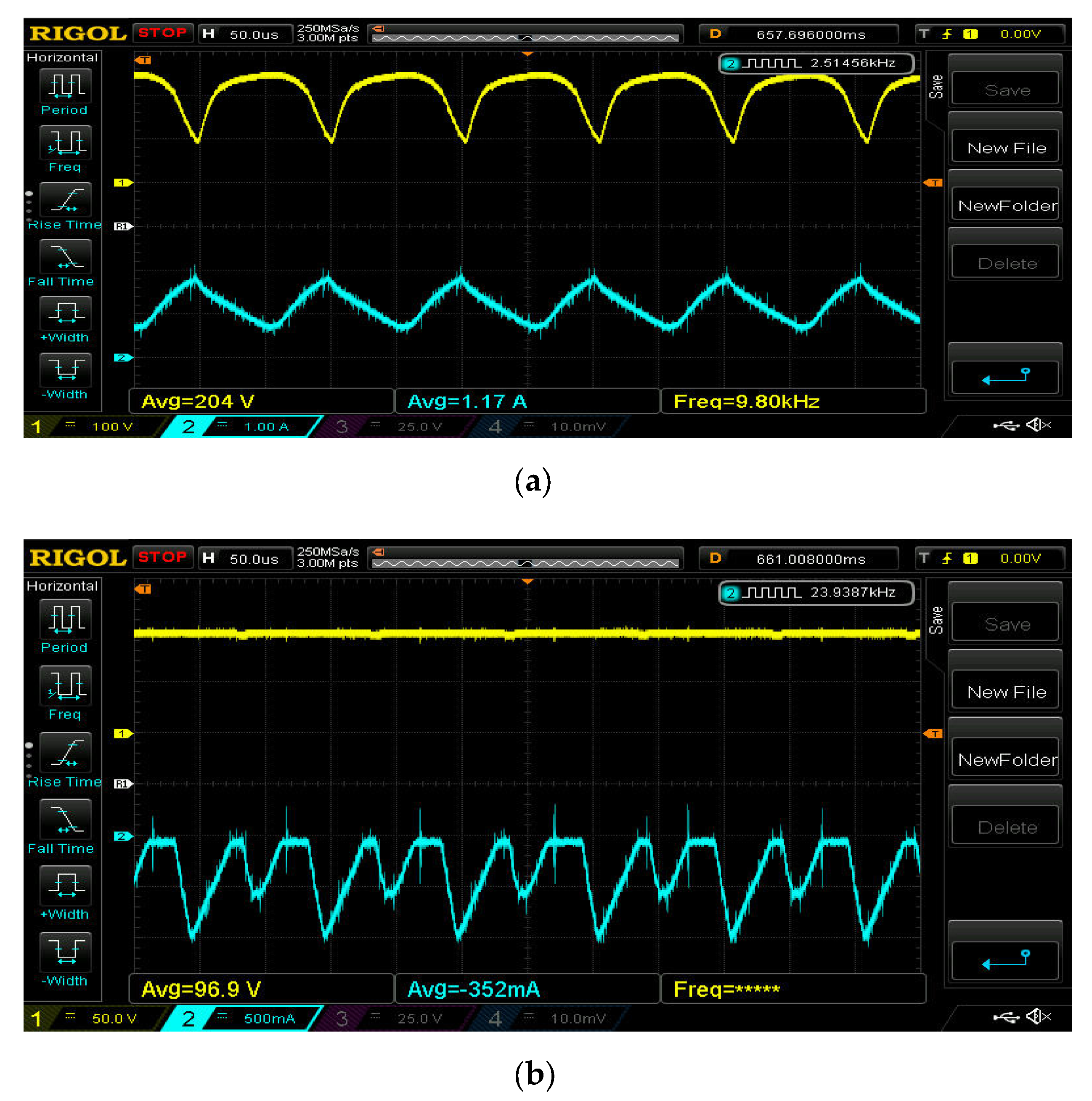
5.1. ESS Charging Domain

In order to balance the power requirement, solar power generation is used. Batteries can also be charged using solar. The functioning of the converter in the ESS charging domain is shown in Figure 9. 372.32 W power is delivered by the solar PV panel. The respective voltage and current are 208 V and 1.79 A. This is shown is Figure 9a. Figure 9b shows the load power, voltage and current are at 159.89 W, 98.7 V and 1.62 A, respectively.
Figure 10a shows diode current of D1 and D0. Diode conduction losses are computed using these current values. Switch voltages and corresponding currents in converter switches S1 to S3 are used to compute the conductive and switching losses. They are shown in Figure 10b–d. The total loss is about 11.87 W, including switches, and diode loss is about 7.20 W; other loss is about 4.67 W.

5.2. ESS Least Domain

In order to balance the power requirement, solar power generation is used. Batteries cannot be charged using solar. Figure 11 illustrates the proposed converter’s operation in the ESS Least Domain. The solar PV panel generates 238.68 watts of electricity. 204 volts and 1.17 amps are the voltage and current values that correspond to each other and shown in Figure 11a,b. The 113.37 W, 96.9 V, and 1.17 A of the load power, voltage, and current are maintained.
Figure 12a shows diode current of D1 and D0. Diode conduction losses are computed using these current values. Switch voltages and corresponding currents in converter switches S1 to S3 are used to compute the conductive and switching losses and are illustrated in Figure 12b–d. The total loss is about 4.03 W, including switches, and diode loss is about 3.20 W; other loss is about 0.83 W.

5.3. ESS Discharging Domain

In order to balance the power requirement, in addition with solar, battery is also used. Figure 13 illustrates a working prototype of the proposed converter in the ESS discharging domain. An impressive 206.98 W are generated by the solar PV panel. 131 V and 0.158 A are the corresponding voltages and currents. Figure 13a,b illustrates this. 188.72 W, 95.8 V, and 1.97 A are the load power, voltage, and current values.
Figure 14a shows diode current of D1 and D0. Diode conduction losses are computed using these current values. Switch voltages and corresponding currents in converter switches S1 to S3 are used to compute the conductive and switching losses. They are shown in Figure 14b–d. The total loss is about 8.87 W, including switch, and diode loss is about 6.53 W; other loss is about 2.45 W. The efficiency of the suggested design with varied outputs and modes of operation is the subject of the preceding discussion. In ESS charging mode, it has 96.5% efficiency; in ESS least mode, it has 98.3% efficiency; and in ESS discharging mode, it has 95.76% efficiency. This experimentation is done with full load condition. Good performance is achieved with large output power range.
Table 3 illustrates the power loss comparison in all of the three domains. In the ESS charging domain, the actual power loss percentage is obtained as 7.43%, which is higher than least, as well as discharging, domains. The ESS least domain has the least value of power loss percentage, obtained as 3.56%. Since the entire power generation will be utilized directly by the load and the battery, charging from the solar power is avoided in this mode. Both the least domain mode and discharge mode loss percentage is less than 5%, and the charging domain mode is around 3% higher than the other two modes. Table 4 indicates the comparison of components and output ports of various TPCs. It can be justified that the suggested TPC has a reduced number of components, thereby decreasing the switching losses of the system.

6. Conclusions

In this research, we have proposed a new three-port bidirectional DC–DC converter, integrated with solar PV and a battery feeding a BLDC motor. The proposed converter has been used for simultaneous power management. Power generation sources are used to charge battery directly, irrespective of load power. The Xilinx board’s FPGA implementation and realistic controller design boost efficiency under heavy load. The theoretical parameters for the prototype converter have been developed in order to validate them. So, the converter’s output efficiency as a whole gets higher. Results clearly indicate that the converter has the capacity to maximize the power from solar PV during radiation, and also has the capability to control the battery during irradiation to maintain the constant value at the output. The proposed design has an efficiency of 96.5% while charging an ESS, 98.3% when discharging, and 95.76 when not charging an ESS. The proposed system can be adopted with a hysteresis comparator approach for automotive fuel pump applications in future.

Author Contributions

Conceptualization, methodology, investigation, resources, writing—original draft preparation, A.K.U.; Data curation, writing—review and editing, R.R.V.R.; Visualization and supervision, M.A.H.; Data curation, writing—review and editing, R.M.E.; Validation, formal analysis, writing—review and editing, A.N.K. and E.H.; All authors have read and agreed to the published version of the manuscript.

Funding

This research received no external funding.

Data Availability Statement

Not applicable.

Conflicts of Interest

The authors declare no conflict of interest.

References

  1. Wang, P.; Wang, W.; Xu, D.; Lu, X. A hardware decoupling method for series-resonance-based isolated three-port DC/DC converters. In Proceedings of the IEEE Applied Power Electronics Conference and Exposition (APEC), SanAntonio, TX, USA, 4–8 March 2018. [Google Scholar] [CrossRef]
  2. Hu, H.; Harb, S.; Fang, X.; Zhang, D.; Zhang, Q.; Shen, Z.J.; Batarseh, I. A three-port flyback for PV microinverter applications with power pulsation decoupling capability. IEEE Trans. Power Electron. 2012, 27, 3953–3964. [Google Scholar] [CrossRef]
  3. Wang, L.; Wang, Z.; Li, H. Asymmetrical duty cycle control and decoupled power flow design of a three-port bidirectional DC-DC converter for fuel cell vehicle application. IEEE Trans. Power Electron. 2011, 27, 891–904. [Google Scholar] [CrossRef]
  4. Wang, Z.; Li, H. An integrated three-port bidirectional DC–DC converter for PV application on a DC distribution system. IEEE Trans. Power Electron. 2012, 28, 4612–4624. [Google Scholar] [CrossRef]
  5. Wu, H.; Chen, R.; Zhang, J.; Xing, Y.; Hu, H.; Ge, H. A family of three-port half-bridge converters for a stand-alone renewable power system. IEEE Trans. Power Electron. 2011, 26, 2697–2706. [Google Scholar] [CrossRef]
  6. Wu, H.; Sun, K.; Chen, R.; Hu, H.; Xing, Y. Full-bridge three-port converters with wide input voltage range for renewable power systems. IEEE Trans. Power Electron. 2012, 27, 3965–3974. [Google Scholar] [CrossRef]
  7. Wu, H.; Sun, K.; Zhu, L.; Xing, Y. An interleaved half-bridge three-port converter with enhanced power transfer capability using three-leg rectifier for renewable energy applications. IEEE Trans. Emerg. Sel. Top. Power Electron. 2015, 4, 606–616. [Google Scholar] [CrossRef]
  8. Wu, H.; Zhang, J.; Qin, X.; Mu, T.; Xing, Y. Secondary-side-regulated soft-switching full-bridge three-port converter based on bridgeless boost rectifier and bidirectional converter for multiple energy interface. IEEE Trans. Power Electron. 2015, 31, 4847–4860. [Google Scholar] [CrossRef]
  9. Zhang, J.; Wu, H.; Qin, X.; Xing, Y. PWM plus secondary-side phase-shift controlled soft-switching full-bridge three-port converter for renewable power systems. IEEE Trans. Ind. Electron. 2015, 62, 7061–7072. [Google Scholar] [CrossRef]
  10. Zhu, H.; Zhang, D.; Athab, H.S.; Wu, B.; Gu, Y. PV isolated three-port converter and energy-balancing control method for PV-battery power supply applications. IEEE Trans. Ind. Electron. 2015, 62, 3595–3606. [Google Scholar] [CrossRef]
  11. Chen, Y.; Wen, G.; Peng, L.; Kang, Y.; Chen, J. A family of cost-efficient non-isaolated single-inductor three-port converters for low power stand-alone renewable power applications. In Proceedings of the Twenty-Eighth Annual IEEE Applied Power Electronics Conference and Exposition (APEC), Long Beach, CA, USA, 17–21 March 2013. [Google Scholar] [CrossRef]
  12. Wang, P.; Zhang, S.; Xu, D.; Lu, X. A series-resonance-based three-port converter with unified autonomous control method in DC microgrids. In Proceedings of the IEEE Applied Power Electronics Conference and Exposition (APEC), SanAntonio, TX, USA, 4–8 March 2018. [Google Scholar] [CrossRef]
  13. Wen, G.; Chen, Y.; Kang, Y. A Family of Cost-efficient Integrated Single-switch Three-port Converters. In Proceedings of the Twenty-Eighth Annual IEEE Applied Power Electronics Conferenceand Exposition (APEC), Long Beach, CA, USA, 17–21 March 2013. [Google Scholar] [CrossRef]
  14. Wu, H.; Sun, K.; Ding, S.; Xing, Y. Topology derivation of nonisolated three-port DC–DC converters from DIC and DOC. IEEE Trans. Power Electron. 2012, 28, 3297–3307. [Google Scholar] [CrossRef]
  15. Zhu, H.; Zhang, D.; Zhang, B.; Zhou, Z. A nonisolated three-port DC–DC converter and three-domain control method for PV-battery power systems. IEEE Trans. Ind. Electron. 2015, 62, 4937–4947. [Google Scholar] [CrossRef]
  16. Zhu, H.; Zhang, D.; Liu, Q.; Zhou, Z. Three-port dc/dc converter with all ports current ripple cancellation using integrated magnetic technique. IEEE Trans. Power Electron. 2015, 31, 2174–2186. [Google Scholar] [CrossRef]
  17. Chien, L.J.; Chen, C.C.; Chen, J.F.; Hsieh, Y.P. Novel three-port converter with high-voltage gain. IEEE Trans. Power Electron. 2014, 29, 4693–4703. [Google Scholar] [CrossRef]
  18. Chen, Y.M.; Huang, A.Q.; Yu, X. A high step-up three-port DC-DC converter for stand-alone PV/battery power systems. IEEE Trans. Power Electron. 2013, 28, 5049–5062. [Google Scholar] [CrossRef]
  19. Marei, M.I.; Alajmi, B.N.; Abdelsalam, I.; Ahmed, N.A. An integrated topology of three-port dc-dc converter for PV-battery power systems. IEEE Open J. Ind. Electron. Soc. 2022, 3, 409–419. [Google Scholar] [CrossRef]
  20. Sobrino-Manzanares, F.; Garrigos, A. Bidirectional, interleaved, multiphase, multidevice, soft-switching, FPGA-controlled, buck–boost converter with PWM real-time reconfiguration. IEEE Trans. Power Electron. 2018, 33, 9710–9721. [Google Scholar] [CrossRef]
  21. Selvamuthukumaran, R.; Gupta, R. Rapid prototyping of power electronics converters for photovoltaic system application using Xilinx System Generator. IET Power Electron. 2014, 7, 2269–2278. [Google Scholar] [CrossRef]
  22. Qian, Z.; Abdel-Rahman, O.; Batarseh, I. An Integrated Four-Port DC/DC Converter for Renewable Energy Applications. IEEE Trans. Power Electron. 2010, 25, 1877–1887. [Google Scholar] [CrossRef]
  23. Wang, P.; Lu, X.; Wang, W.; Xu, D. Frequency Division Based Coordinated Control of Three-Port Converter Interfaced Hybrid Energy Storage Systems in Autonomous DC Microgrids. IEEE Access 2018, 6, 25389–25398. [Google Scholar] [CrossRef]
  24. Duarte, J.L.; Hendrix, M.; Simões, M.G. Three-port bidirectional converter for hybrid fuel cell systems. IEEE Trans. Power Electron. 2007, 22, 480–487. [Google Scholar] [CrossRef] [Green Version]
  25. Tao, H.; Kotsopoulos, A.; Duarte, J.L.; Hendrix, M.A. Transformer-coupled multiport ZVS bidirectional dc–dc converter with wide input range. IEEE Trans. Power Electron. 2008, 23, 771–781. [Google Scholar] [CrossRef]
  26. Tao, H.; Duarte, J.L.; Hendrix, M.A. Three-port triple-half-bridge bidirectional converter with zero-voltage switching. IEEE Trans. Power Electron. 2008, 23, 782–792. [Google Scholar] [CrossRef]
  27. Krishnaswami, H.; Mohan, N. Three-port series-resonant dc–dc converter to interface renewable energy sources with bidirectional load and energy storage ports. IEEE Trans. Power Electron. 2009, 24, 2289–2297. [Google Scholar] [CrossRef]
  28. Al-Atrash, H.; Tian, F.; Batarseh, I. Tri-modal half-bridge converter topology for three-port interface. IEEE Trans. Power Electron. 2007, 22, 341–345. [Google Scholar] [CrossRef]
  29. Zhang, B.; Hong, D.; Wang, T.; Zhang, Z.; Wang, D. A novel two-phase interleaved parallel bi-directional DC/DC converter. Arch. Electr. Eng. 2021, 70, 219–231. [Google Scholar] [CrossRef]
  30. Jalbrzykowski, S.; Citko, T. A bidirectional DC-DC converter for renewable energy systems. Bull. Pol. Acad. Sci. Tech. Sci. 2009, 57, 363–368. [Google Scholar] [CrossRef]
  31. Kirim, Y.; Sadikoglu, H.; Melikoglu, M. Technical and economic analysis of biogas and solar photovoltaic (PV) hybrid renewable energy system for dairy cattle barns. Renew. Energy 2022, 188, 873–889. [Google Scholar] [CrossRef]
  32. Rahman, S.; Saha, S.; Islam, S.N.; Arif, M.T.; Mosadeghy, M.; Haque, M.E.; Oo, A.M. Analysis of power grid voltage stability with high penetration of solar PV systems. IEEE Trans. Ind. Electron. 2021, 57, 2245–2257. [Google Scholar] [CrossRef]
  33. Debnath, S.; Marthi, P.R.; Xia, Q.; Pan, J.; Saeedifard, M.; Vipin, V.N.; Chakraborty, S.; Arifujjaman, M. Renewable Integration in Hybrid AC/DC Systems Using a Multi-Port Autonomous Reconfigurable Solar Power Plant (MARS). IEEE Trans. Power Syst. 2020, 36, 603–612. [Google Scholar] [CrossRef]
  34. Ghenai, C.; Bettayeb, M. Design and optimization of grid-tied and off-grid solar PV systems for super-efficient electrical appliances. Energy Efficiency. Energy Effic. 2020, 13, 291–305. [Google Scholar] [CrossRef]
  35. Singh, S.; Veda, S.; Singh, S.P.; Jain, R.; Baggu, M. Event-Driven Predictive Approach for Real-Time Volt/VAR Control With CVR in Solar PV Rich Active Distribution Network. IEEE Trans. Power Syst. 2021, 36, 3849–3864. [Google Scholar] [CrossRef]
  36. Putri, R.I.; Rifa’i, M.; Adhisuwiginjo, S. Design of Buck Converter For Photovoltaic System Applications. In Proceedings of the 2015 Applied Electromagnetic Technology AEMT, Lombok, Indonesia, 11–15 April 2015. [Google Scholar]
  37. Aragon-Aviles, S.; Kadam, A.H.; Sidhu, T.; Williamson, S.S. Modeling, Analysis, Design, and Simulation of a Bidirectional DC-DC Converter with Integrated Snow Removal Functionality for Solar PV Electric Vehicle Charger Applications. Energies 2022, 15, 2961. [Google Scholar] [CrossRef]
  38. Kahani, R.; Jamil, M.; Iqbal, M.T. Direct Model Reference Adaptive Control of a Boost Converter for Voltage Regulation in Microgrids. Energies 2022, 15, 5080. [Google Scholar] [CrossRef]
  39. Koca, Y.B.; Aslan, Y.; Yonetken, A.; Oguz, Y. Boost Converter Design and Analysis for Photovoltaic Systems. In Proceedings of the International Conference on Engineering Technology and Applied Sciences (ICETAS), Kiev, Ukraine, 24–28 April 2019. [Google Scholar]
  40. Bhukya, L.; Kedika, N.R.; Salkuti, S.R. Enhanced Maximum Power Point Techniques for Solar Photovoltaic System under Uniform Insolation and Partial Shading Conditions: A Review. Algorithms 2022, 15, 365. [Google Scholar] [CrossRef]
  41. Mudhol, A.; Pius, A.J.P. Design and implementation of boost converter for photovoltaic systems. Int. J. Innov. Res. Electr. Electron. Instrum. Control. Eng. 2016, 4, 110–114. [Google Scholar] [CrossRef]
  42. Zulkifli, M.Z.; Azri, M.; Alias, A.; Talib, N.; Lazi, J.M. Simple control scheme buck-boost DC-DC converter for stand alone PV application system. Int. J. Power Electron. Drive Syst. 2019, 10, 1090–1101. [Google Scholar] [CrossRef]
  43. Danyali, S.; Aghaei, O.; Shirkhani, M.; Aazami, R.; Tavoosi, J.; Mohammadzadeh, A.; Mosavi, A. A New Model Predictive Control Method for Buck-Boost Inverter-Based Photovoltaic Systems. Sustainability 2022, 14, 11731. [Google Scholar] [CrossRef]
  44. Mahdi, A.S.; Mahamad, A.K.; Saon, S.; Tuwoso, T.; Elmunsyah, H.; Mudjanarko, S.W. Maximum power point tracking using perturb and observe, fuzzy logic and ANFIS. SN Appl. Sci. 2020, 2, 89. [Google Scholar] [CrossRef] [Green Version]
  45. Kumar, D.G.; Ganesh, A.; Sireesha, N.V.; Kshatri, S.S.; Mishra, S.; Sharma, N.K.; Bajaj, M.; Kotb, H.; Milyani, A.H.; Azhari, A.A. Performance Analysis of an Optimized Asymmetric Multilevel Inverter on Grid Connected SPV System. Energies 2022, 15, 7665. [Google Scholar] [CrossRef]
  46. Shengqing, L.; Fujun, L.; Jian, Z.; Wen, C.; Donghui, Z. An improved MPPT control strategy based on incremental conductance method. Soft Comput. 2020, 24, 6039–6046. [Google Scholar] [CrossRef]
  47. Yusof, N.F.M.; Ishak, D.; Salem, M. An Improved Control Strategy for Single-Phase Single-Stage Grid-Tied PV System Based on Incremental Conductance MPPT, Modified PQ Theory, and Hysteresis Current Control. Eng. Proc. 2021, 12, 91. [Google Scholar] [CrossRef]
  48. Jately, V.; Azzopardi, B.; Joshi, J.; Sharma, A.; Arora, S. Experimental analysis of hill-climbing MPPT algorithms under low irradiance levels. Renew. Sustain. Energy Rev. 2021, 150, 111467. [Google Scholar] [CrossRef]
  49. Kamran, M.; Mudassar, M.; Fazal, M.R.; Asghar, M.U.; Bilal, M.; Asghar, R. Implementation of improved Perturb & Observe MPPT technique with confined search space for standalone photovoltaic system. J. King Saud Univ. Eng. Sci. 2020, 32, 432–441. [Google Scholar] [CrossRef]
  50. Motahhir, S.; El Ghzizal, A.; Sebti, S.; Derouich, A. Modeling of photovoltaic system with modified incremental conductance algorithm for fast changes of irradiance. Int. J. Photoenergy 2018, 2018, 3286479. [Google Scholar] [CrossRef] [Green Version]
  51. Zhu, W.; Shang, L.; Li, P.; Guo, H. Modified hill climbing MPPT algorithm with reduced steady-state oscillation and improved tracking efficiency. J. Eng. 2018, 17, 1878–1883. [Google Scholar] [CrossRef]
  52. Pillot, B.; Muselli, M.; Poggi, P.; Dias, J.B. Historical trends in global energy policy and renewable power system issues in Sub-Saharan Africa: The case of solar PV. Energy Policy 2019, 127, 113–124. [Google Scholar] [CrossRef]
  53. Mumtaz, F.; Yahaya, N.Z.; Meraj, S.T.; Singh, B.; Kannan, R.; Ibrahim, O. Review on non-isolated DC-DC converters and their control techniques for renewable energy applications. Ain Shams Eng. J. 2021, 12, 3747–3763. [Google Scholar] [CrossRef]
  54. Alijarajreh, H.; Lu, D.D.-C.; Siwakoti, Y.P.; Tse, C.K. A Nonisolated Three-Port DC–DC Converter with Two Bidirectional Ports and Fewer Components. IEEE Trans. Power Electron. 2022, 37, 8207–8216. [Google Scholar] [CrossRef]
  55. Kumar, M.; Barbosa, P.M.; Ruiz, J.M.; Minli, J.; Hao, S. Isolated Three-Port Bidirectional DC-DC Converter for Electric Vehicle Applications. In Proceedings of the IEEE Applied Power Electronics Conferenceand Exposition (APEC), Houston, TX, USA, 20–24 March 2022. [Google Scholar] [CrossRef]
  56. Wu, Y.-E. Novel High-Step-Up/Step-Down Three-Port Bidirectional DC/DC Converter for Photovoltaic Systems. Energies 2022, 15, 5257. [Google Scholar] [CrossRef]
  57. Cheng, T.; Lu, D.D.-C.; Qin, L. Non-Isolated Single-Inductor DC/DC Converter With Fully Reconfigurable Structure for Renewable Energy Applications. IEEE Trans. Circuits Syst. II Express Briefs Copy 2018, 65, 351–355. [Google Scholar] [CrossRef]
  58. Shen, C.L.; Shen, Y.S.; Chiu, P.C.; Liang, T.C. Isolated bidirectional converter with minimum active switches for highvoltage ratio achievement and micro-grid applications. IET Power Electron. 2017, 10, 2208–2216. [Google Scholar] [CrossRef]
Figure 1. Proposed TPC DC–DC Structure.
Energies 16 00624 g001
Figure 2. PV solar cell’s equivalent circuit.
Energies 16 00624 g002
Figure 3. Mode Wave Form for ESS Discharging Domain.
Energies 16 00624 g003
Figure 4. Comparable circuit: (a) Mode I (a); (b) Mode I (b); (c) Mode I (c); (d) Mode I (d).
Energies 16 00624 g004
Figure 5. Mode Wave Form for ESS Charging Domain.
Energies 16 00624 g005
Figure 6. Comparable circuit: (a) Mode II (a); (b) Mode II (b); (c) Mode II (c); (d) Mode II (d).
Energies 16 00624 g006
Figure 7. Control loop operation of proposed TPC.
Energies 16 00624 g007
Figure 8. The Experimental Setup.
Energies 16 00624 g008
Figure 9. The functioning of the converter in the ESS charging domain: (a) Experimental Wave Form of PV; (b) Battery in ESS Charging Domain.
Energies 16 00624 g009
Figure 10. Experimental Wave Form of Switch and Diode in ESS Charging Domain.
Energies 16 00624 g010
Figure 11. Experimental Wave Form of PV and Battery in ESS Least Domain.
Energies 16 00624 g011
Figure 12. Experimental Wave Form of Switch and Diode in ESS Least Domain.
Energies 16 00624 g012
Figure 13. Experimental Wave Form of PV and Battery in ESS Discharging Domain.
Energies 16 00624 g013
Figure 14. Experimental Wave Form of Switch and Diode in ESS Discharging Domain.
Energies 16 00624 g014
Table 1. Input and Output Specifications.
Degree (°)Switching States of PWM Inverter
S1S2S3S4S5S6
0–60100100
60–120100001
120–180001001
180–240011000
240–300000110
300–360000110
Table 2. Input and Output Specifications.
ParameterValue
Solar PV panel Specifications at Standard Test Conditions (STC)
Input power (180 W solar PV panel–10 Nos. connected in series)1800 W
Voc(Open circuit voltage in volts)42.48 V
Isc(Short Circuit current in Ampere)4.8 A
Vmp(Voltage at MPP condition)36 V
Imp (Current at MPP condition)5 A
Cell Temperature at STC25 °C
Irradiance at STC1000 W/m2
Load–BLDC Motor Drive
Power Rating250 W
Voltage Rating110 V
Speed1500 RPM
Torque12 N-m
Storage Battery Specifications
Voltage Rating24 V
Battery Capacity135 Ah
DC–DC Converter Specifications
Inductor L1, L2320 μH
Capacitor C01000 μF
Table 3. Power Loss Comparison in all the Domains.
DescriptionSwitching Loss (W)Other Losses (W)Total Power Loss (W)Loss Percentage (%)
ESS charging domain7.204.6711.877.43
ESS least Domain3.200.834.033.56
ESS Discharging domain6.532.458.874.71
Table 4. Comparison of Components and Output Ports of Various TPCs.
Component Type[8][10][57][58]Proposed
MOSFETs63443
Diodes23502
Capacitors45331
Inductors22102
Input Ports22222
Output Ports22222
Disclaimer/Publisher’s Note: The statements, opinions and data contained in all publications are solely those of the individual author(s) and contributor(s) and not of MDPI and/or the editor(s). MDPI and/or the editor(s) disclaim responsibility for any injury to people or property resulting from any ideas, methods, instructions or products referred to in the content.

