Abstract
This paper presents the design and modeling procedure of a wireless power transfer (WPT) system applied to In-wheel-motor (IWM). The system is designed to transmit over 10 kW of power following the physical constraints faced by the IWM applications. The issues of coil misalignment and load change are discussed as particular scenarios in IWM. The finite element model is built for circular, rectangular, and double-D coils, finding that the rectangular coil has the best performance considering the transmission interval and misalignment resistance. The circuit design procedure is presented, and the analysis of the influence of load and mutual inductance change on the WPT system is addressed. Finally, the performance of the design is verified with experiments on a full-scale prototype. It is proved that the WPT system successfully transmits 10 kW of power with a DC–DC efficiency of over 90% under a transmission interval of 140 mm. The output voltage is stable under 40 mm coil misalignment scenarios and over 50% load change.
1. Introduction
Although the concept of power transmission without wires was introduced by Nikola Tesla more than a century ago [1], it was only recently that researchers massively developed it. The WPT (WPT) technology offers a brand new kind of energy supplement for all the devices that are driven by electricity, including but not limited to portable electronic devices [2], electrical vehicles [3], and implantable biomedical devices [4]. WPT is safe and flexible [5]. It offers considerable advantages in harsh working conditions where power transmission via wires is unreliable or impossible [6].
WPT systems can be categorized into far-field and near-field power transfers due to their different applications [5]. Far-field transfer uses electromagnetic waves to transfer energy. It can be divided into two groups: microwave power transfer [7] and laser power transfer [8]. Although the transmission distance of far-field power transfer is long, It has the significant disadvantage of low transmission efficiency. The efficiency of both microwaves and lasers are at most 10% [9].
On the other hand, near-field transfer transfers the energy through an electric or magnetic field [10]. A capacitive power transfer system is designed to transfer energy wirelessly through an electric field that builds with flat capacitors [11]. This technology is affordable, but the transfer distance is strongly limited (several millimeters). The other approach is to transfer energy with a magnetic field, in which both transmitter and receiver sides are coils [12]. A particular approach for the magnetic-field-based power transfer is to add compensation blocks on the coils of both sides to create resonance circuits, where the system impedance is greatly reduced [13]. This approach is called magnetically coupled resonance wireless power transfer(MCRWPT). It was first introduced by researchers in [14]. The significant advantages of MCRWPT are its high efficiency and long power transfer distance.
The optimal design of the magnetic resonance coupler has become an important issue in achieving energy transfer performance considering physical constraints such as weight and size. Different coil geometries are considered, for example, circular [15], rectangular [16], double-D [17], and pentagonal shape [18]. A comparative study in [18] shows that for various coil sizes and transmission intervals, the magnetic coupling coefficient of different coil geometries changes, which means the optimal design of the magnetic coupler in different applications is varied in real-world scenarios. The selection of ferromagnetic materials is another essential aspect in the design of magnetic resonance couplers. In [19], various materials, including ferrite, sendust, iron dust, and NiZn alloy are applied. Results show that ferrite material is the best candidate for the extensive range of frequencies used (10 to 140 kHz).
The most popular application of WPT is wireless charging in electric vehicles, where the traditional conductive charging through a bulky gauge cable is upgraded [3]. With transmission winding placed beneath the parking area or buried in the road, the charging process becomes automated [20]. Another application is to transmit power to machine armature in a wireless way, referred to as a wireless machine in some of the literature [21]. In [22], the WPT technology is applied to power the IWMs, where the power cables between the vehicle chassis and the wheel are replaced. In this way, only mechanical connections remain between the vehicle chassis and the wheels. Both parts can be sealed and provide better protection against harsh environments. However, this architecture still follows the original WPT architecture. The current on the receiver side is rectified to DC and applied to the motor controller with power electronic devices. In some following research, WPT works as the power delivery method and replaces the power electronic devices on the receiver side. In [23], the power transferred wirelessly is directly applied to drive a DC servo motor. With the multi-receiver structure tuned to various resonance frequencies, the motor rotation direction is controlled by applying different frequencies on the transmission side. The same idea is also applied to shaded-pole induction motors [24] and the switched reluctance motor [25].
The IWM system has better robustness when the cables are replaced with magnetic resonance coupling WPT. However, the misalignment between transmitter and receiver coils caused by the inevitable vibration during the motion of the IWM becomes an essential issue for the application. In addition, since the load of an IWM–WPT system is a motor instead of a battery, the sudden load change is another critical issue for design.
The design procedure for the WPT system is a problem that combines mechanical, electrical, and magnetic design [26]. Although many researchers have shed light on the comprehensive design of the WPT system, their target has mainly been wireless charging applications [27], and the analysis on the issue of coil misalignment and load change is scarce. In this study, the design procedure is focused on applying the WPT system to the IWM, where the power rating is high and variable and the issue of misalignment is significant. The major contributions of this study are listed as follows:
- Comprehensive FEM models are built for three popular coil geometries: circular coils, rectangular coils, and double-D coils. Their performances under the same physical design constraints are discussed. A further discussion is made on the influence of the coil coverage ratio and the shape of ferrite on the rectangular coils.
- An analysis is conducted on the influence of system parameter change. Changes of mutual inductance (effected by misalignment) and load (analyzed with equivalent resistance) are the most common when applying the WPT system for IWM. Their influence on transmitting power is discussed with theoretical analysis.
- The electric circuit of the WPT system is modeled and analyzed. The model of the WPT is verified by experiments performed on a prototype. The overall efficiency of the system is verified. The prototype is also tested under particular working conditions of misalignment and load change in the IWM application.
The structure of the following sections in this paper is listed as follows: Section 2 introduces the basic electrical topology of the target WPT system, and the physical constraints are illustrated. In Section 3, the electromagnetic design of the magnetic resonance coupler is illustrated. Important issues such as the axial interval, performance under misalignment, coil coverage ratio, and ferrite structure are discussed. In Section 4, the circuit design of the WPT system is introduced. The discussion addresses the influence of mutual inductance and load change. A prototype of the designed WPT system is built, and the experiment results are shown in Section 5. Finally, a conclusion is made in Section 6.
2. Design Constraints and System Topology
2.1. Design Constraints Based on the IWM Working Condition
In this study, the designed WPT system is for an IWM application. The electrical and mechanical design should follow the design guidelines and constraints in Table 1.

Table 1.
Design guidelines and constraints.
2.2. Overall Topology of the WPT System
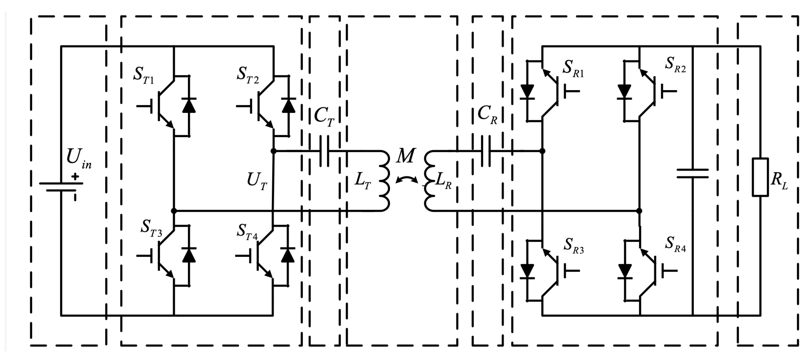
The topology of a loosely coupled WPT system is shown in Figure 1.

Figure 1.
The overall topology of the WPT system.
As shown in Figure 1, a WPT consists of seven parts: DC voltage input, transmitter side high-frequency inverter, transmitter side compensation capacitor, the magnetic coupling structure, receiver side compensation capacitor, receiver side rectifier with filter, and the load.
The high-frequency inverter of the transmitter side is a full-bridge inverter unit composed of four transistors. During operation, , and , conduct alternately to generate a high-frequency square wave voltage. Through a resonance circuit with compensation capacitors, a sinusoidal alternating current of the same frequency is generated on the transmitter coil. The power is transmitted to the receiver coil wirelessly through the high-frequency alternating magnetic field. After a rectifier and filter capacitor, a stable DC voltage is transmitted to the load side.
The relationship between the transmitter and receiver sides’ current and voltage is described with Equation (1).
The magnetic coupling k between the transmitter and receiver coils is defined as
Thus, the transmitted power on the load side () and the system’s overall efficiency () are functions related to the coupling coefficient (or mutual inductance).
where the value of the mutual inductance is most important in the WPT design procedure. It is decided by the electromagnetic character of the magnetic coupler. The design procedure of the magnetic resonance coupler is discussed in the following section.
3. FEM-Based Electromagnetic Model of the Magnetic Resonance Coupler
The magnetic coupler is the core device of a WPT system. The system efficiency and operational performance are determined by the design of the magnetic coupler. Three geometry types of magnetic couplers are commonly applied for WPT design in EV applications: namely, circular coils, rectangular coils, and double-D coils. In this section, 3D models of the three geometries mentioned above types are built for analyses with the finite element method (FEM). The simulation results on magnetic flux density under various axial intervals between coils are shown. The variations of mutual inductance and magnetic coupling k under misalignment are explored.
3.1. FEM Analysis of Maximum Flux Density
The physical parameters for circular, rectangular, and double-D coils follow the same constraints to ensure a fair comparison. The Litz wire diameters, number of turns, and the arrangements of the ferrite for three geometries are set to be the same. A current supply of 30 A is applied to the cross-section of each coil in the FEM. Detailed information about them is shown in Table 2.

Table 2.
The parameters for all three coil geometries.
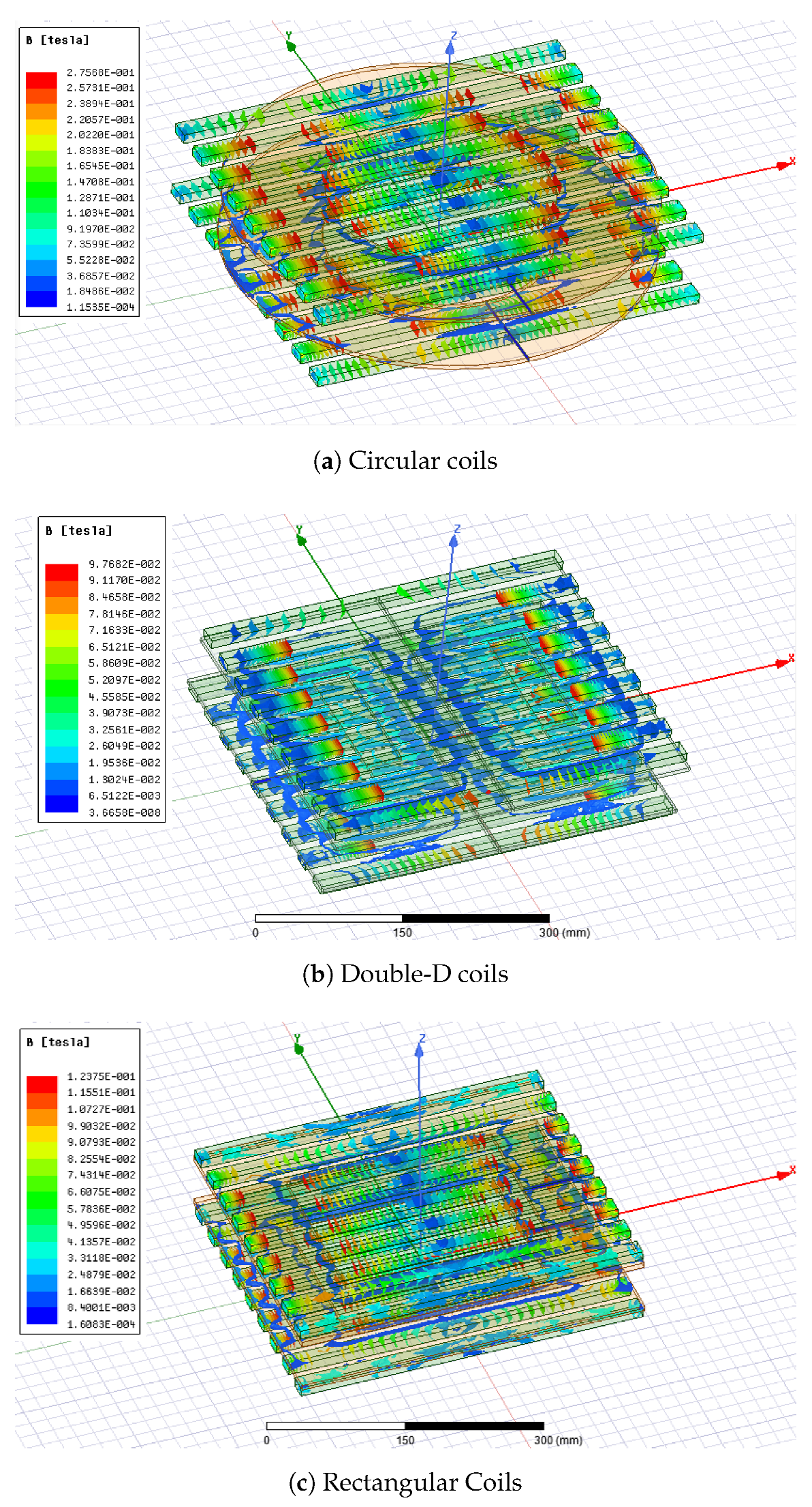
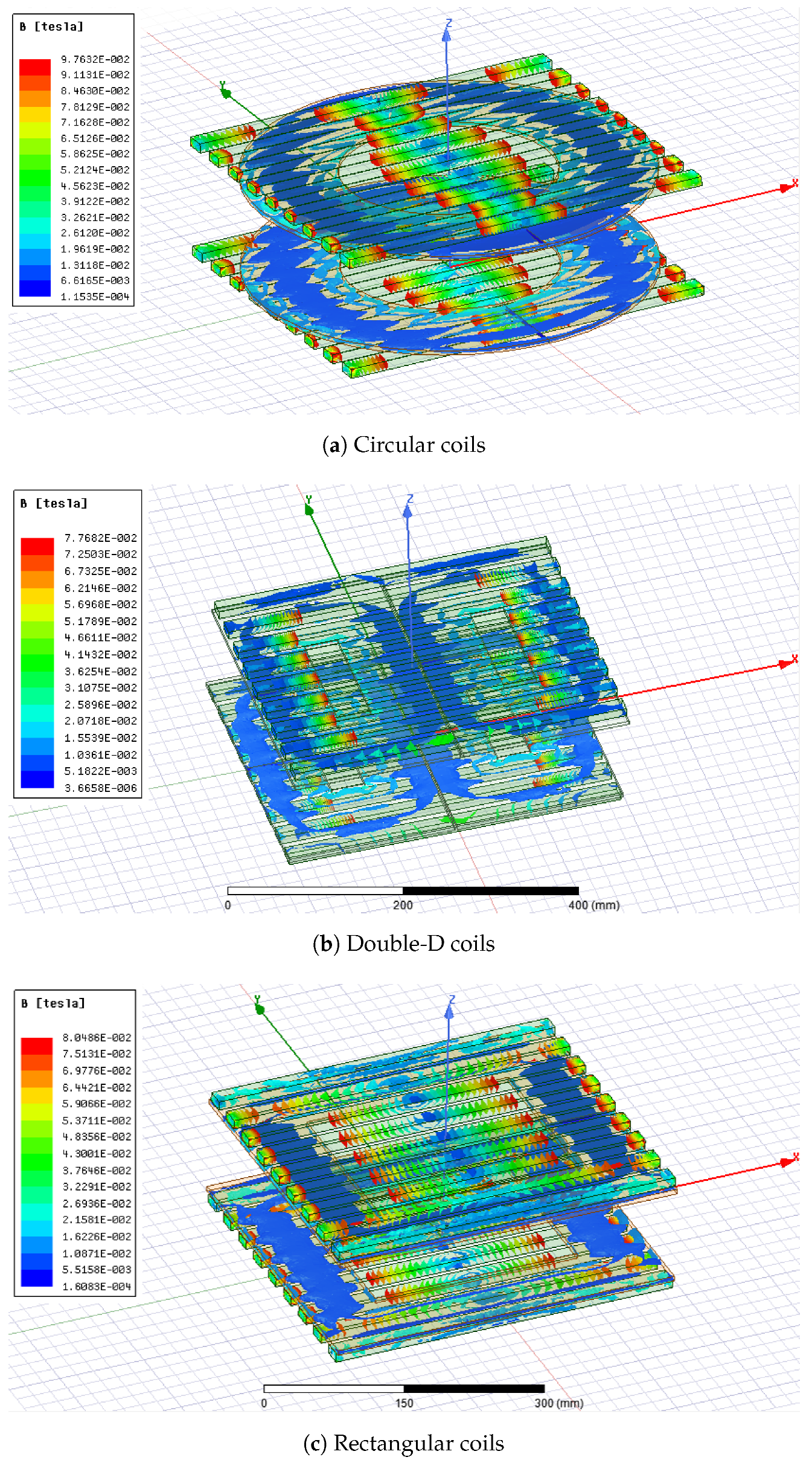
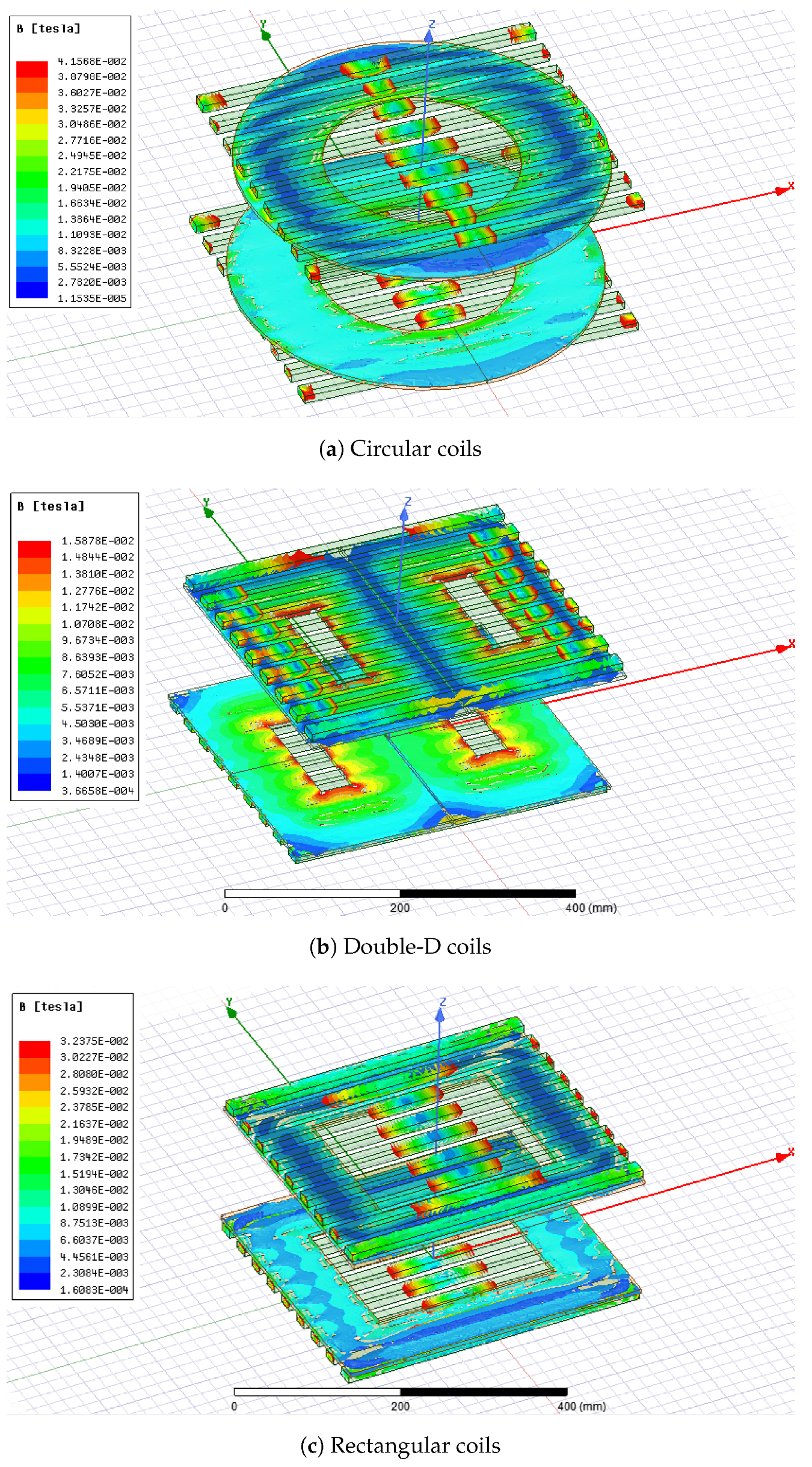
The FEM result of the magnetic field of various coil geometries is shown in Figure 2, Figure 3 and Figure 4. Figure 2 shows the magnetic flux density when the axial interval between the transmitter and receiver coil is 50 mm. In the 50 mm condition, the magnetic flux has primarily surrounded the coil in all three geometries. The circular coil has the biggest maximum magnetic flux density. The value is T. The magnetic flux density for rectangular and double-D coils is smaller than the circular coil. Their values are T and T, respectively. The simulation results for the 100 mm axial interval cases are shown in Figure 3. In that case, the circular coil still has the biggest maximum magnetic flux density of T. The value for the rectangular coil is T, while the value for the double-D coil is T. The simulation results for the 150 mm axial interval cases are shown in Figure 4. The result for the circular coil is T, while for the rectangular coil, it is T. For the double-D coil, the maximum flux density is T. As the axial interval increases, the maximum flux density point has moved from the centre of the full double-D coil to the center of the individual “D” in the coil.

Figure 2.
Three-dimensional magnetic field distribution in three coil geometries with 50 mm axial interval.

Figure 3.
Three-dimensional magnetic field distribution in three coil geometries with 100 mm axial interval.

Figure 4.
Three-dimensional magnetic field distribution in three coil geometries with 150 mm axial interval.
3.2. Magnetic Coupling with Various Axial Intervals
The FEM simulation results in Figure 2, Figure 3 and Figure 4 revealed that the maximum flux density has a negative correlation with the axial interval between transmitter and receiver coils.
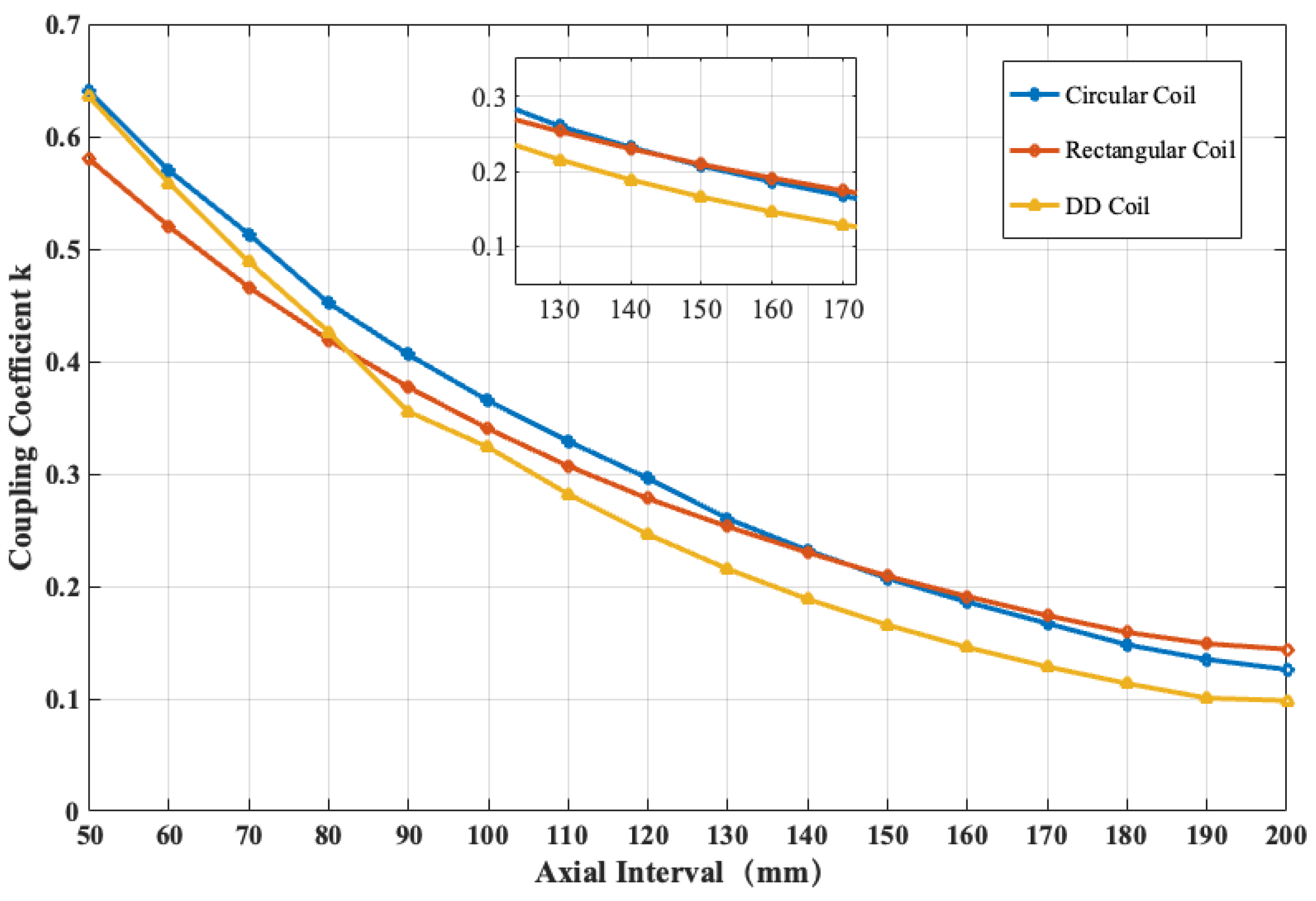
The coupling coefficient is defined as Equation (2). The coupling coefficient’s changing pattern is more important in a WPT system’s numerical design. The relationship between the magnetic coupling and the coils’ axial interval is explored in this part. The coils are aligned with their center but with various axial intervals. The simulation results are shown in Figure 5.

Figure 5.
Magnetic coupling variation of coils under different axial intervals.
It is shown that the circular coil has the highest coupling coefficient from the axial interval of 50 mm to 80 mm, while the value for the rectangular coil is the lowest. When the axial spacing increased from 80 mm to 150 mm, the coupling coefficient of the double-D coil dropped dramatically, and the values for circular and rectangular coils were similar. When the axial spacing is between 150 mm and 200 mm, the coupling coefficient of the rectangular coil is the highest. In contrast, the coupling coefficient of the double-D coil becomes the lowest, and the coupling coefficient of the circular coil is slightly lower than the rectangular one.
The rectangular coil is the least sensitive to the change in axial interval. On the other hand, the double-D coil is most sensitive to the axial interval change, which may result from its less concentrated topology, where the magnetic flux is separated into two parts. In practical applications of WPT, large transmission distances are sometimes inevitable in design. One should consider the potential change in the axial interval.
3.3. Magnetic Coupling under Coil Misalignment
This part explores the conditions of coupling coefficient changes with transmitter and receiver coil misalignment. The simulation results for all three geometries with a misalignment distance from zero to 240 mm are given. For the circular coils, the definition of a misalignment interval is the horizontal interval between the transmitter and receiver. Thus, there is only one possible misalignment direction. As the length and width of the rectangular and double-D coils are different, both directions are tested. The 3D models of rectangular and double-DD coils are shown in Figure 6, with the definition of the X–Y direction marked on the figure.

Figure 6.
Coil modeling and direction definitions.
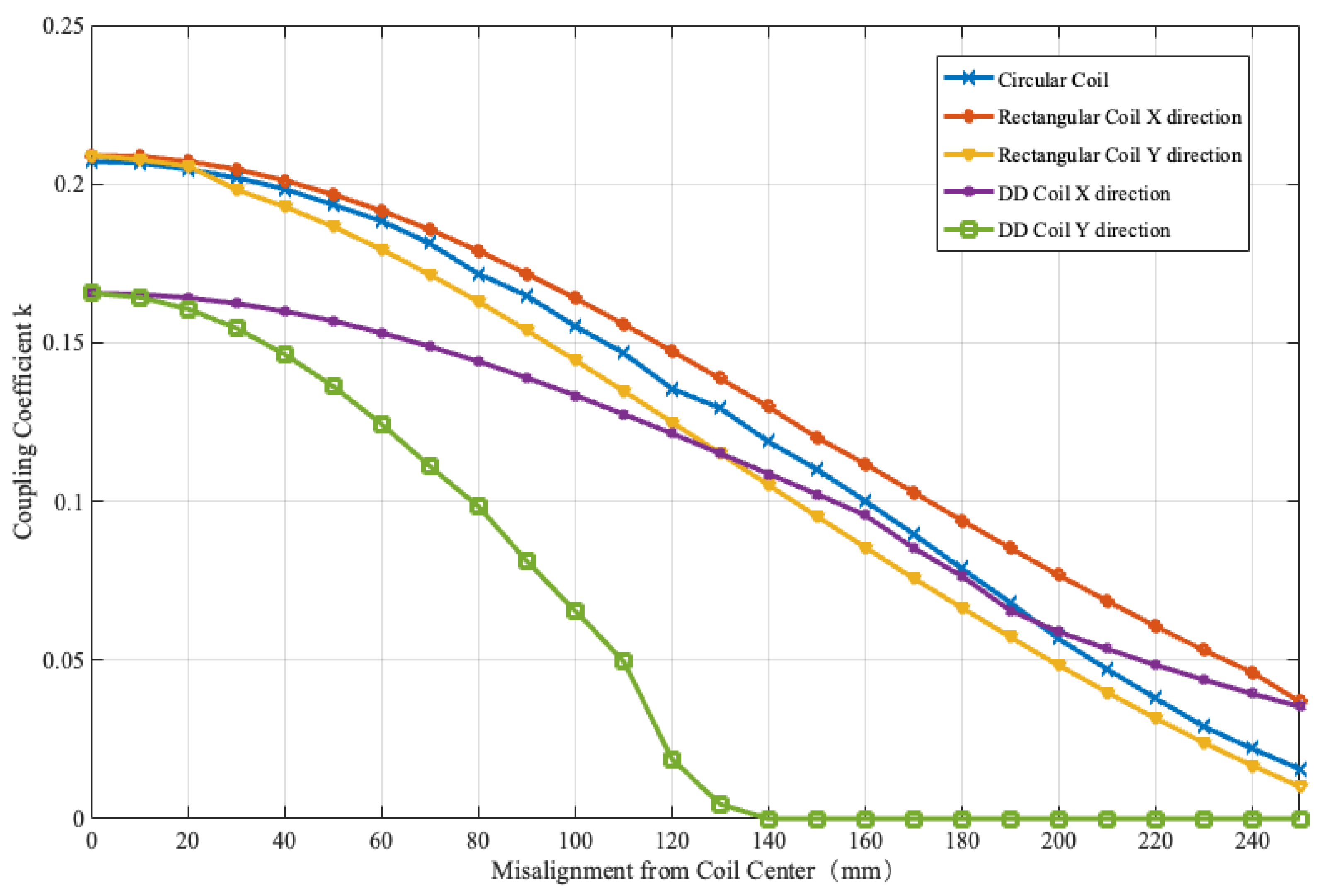
All the results are tested under an axial interval of 150 mm. The simulation results are shown in Figure 7.

Figure 7.
Magnetic coupling variation of coils under different misalignments.
According to Figure 7, the changing patterns of the coupling coefficient for circular and rectangular coils share some similarities. They start from the same point of . The decrease ratio for both coils is decent. At the maximum distance of 240 mm in this simulation, the final value of the circular coil is between the value of the rectangular coil in the X and Y directions. For the double-D coil, the decrease rate in the X direction is the fastest among all five sets of simulations. The value drops to 0 at mm. Meanwhile, its decrease rate in the Y direction is slowest. Although the coupling coefficient for the DD coil is smaller at the zero misalignment point, it exceeds the circular coil at the misalignment distance of 190 mm. The double-D coil geometry is an ideal option in applications where the misalignment direction is specific.
However, in the WPT system design in this study, the axial interval for the transmission and receiver coil is 140 mm. The simulation results of Figure 5 and Figure 7 show that the rectangular coil has the most significant overall coupling coefficient under various misalignment conditions. Thus, it is selected as the target geometry topology.
3.4. Magnetic Coupling with Various Coil Covering Ratios
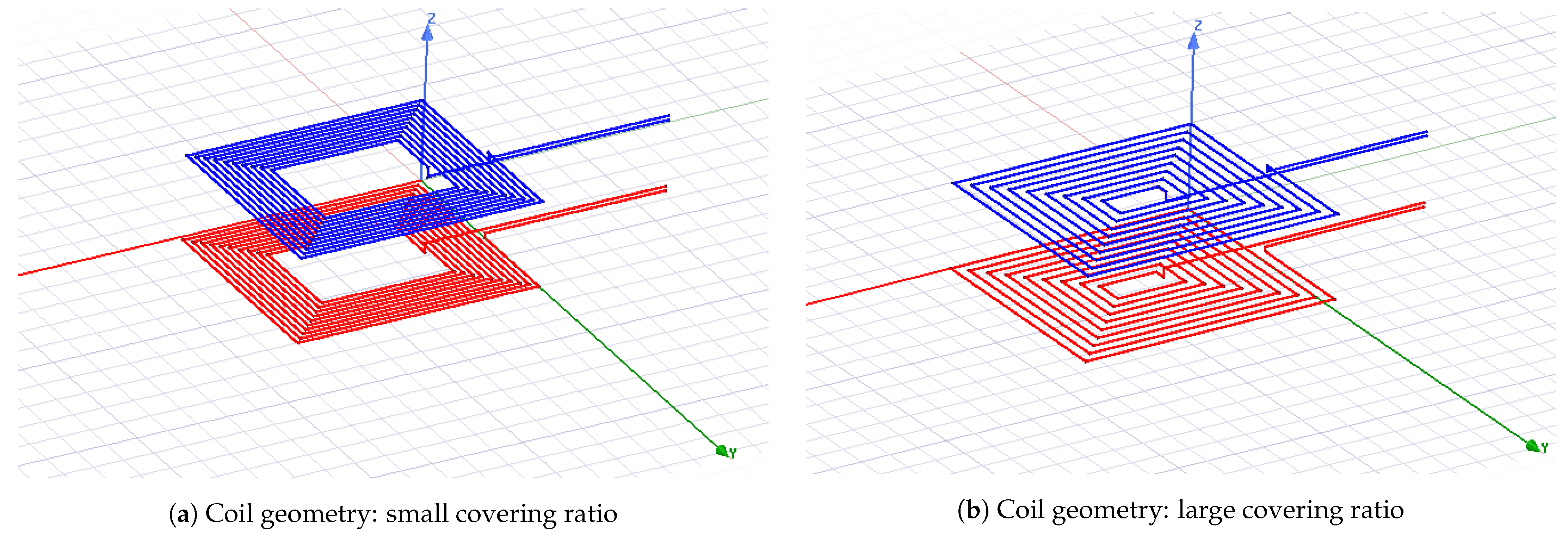
The physical character of a rectangular coil is also affected by its coverage ratio. For a rectangular coil with fixed width a, length b, and number of turns n, we denote the gap between wires as p. The coverage ratio is defined as Equation (4).
The case of a small is shown in Figure 8a, while the case of a large is shown in Figure 8b. A comparison of the effect of various covering ratios on the magnetic coupling is made to find the optimal coverage ratio.

Figure 8.
Coil geometry of various covering ratios.
The simulation is carried out on the rectangular coil. The detailed information for the Maxwell simulation is shown in Table 3.

Table 3.
Parameters for the rectangular coil for covering ratio simulation.
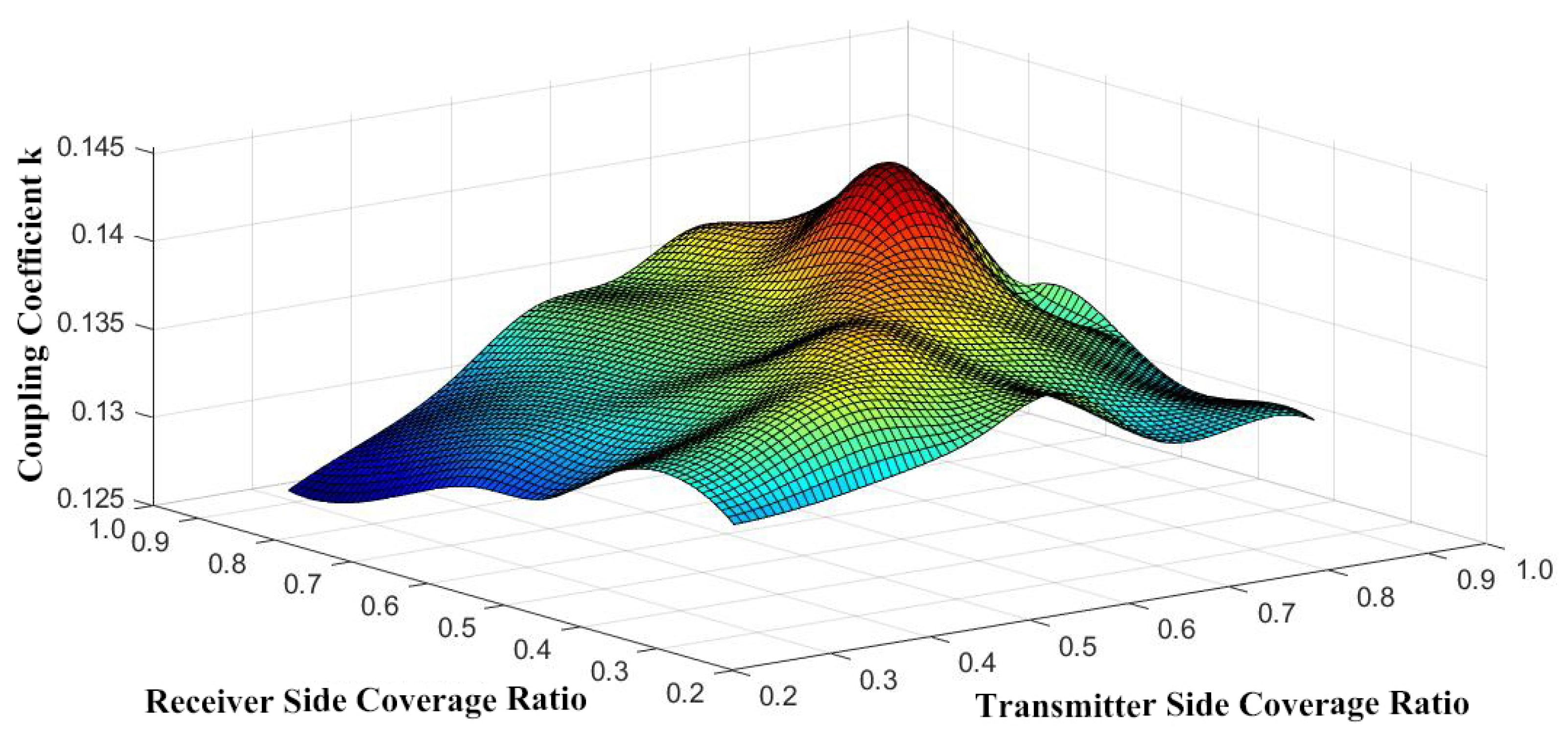
The summary of the simulation result is shown in Figure 9. It is observed that when the of the receiver coil is fixed, the coupling coefficient k increases first and then decreases with the increase of the transmitter coil . A similar pattern is observed for the receiver coil regarding the transmitter side.

Figure 9.
Magnetic coupling variation under various covering ratios.
The maximal coupling coefficient is found when the coverage ratio at both sides is , and the maximum coupling coefficient k is 0.14536.
3.5. The Design of Ferrite Structure
The mutual inductance for coils without ferrite material cannot satisfy the requirement of high power transmission within the required size constraint. As a result, the design of high-permeability ferrite material placed beneath the coils is essential.
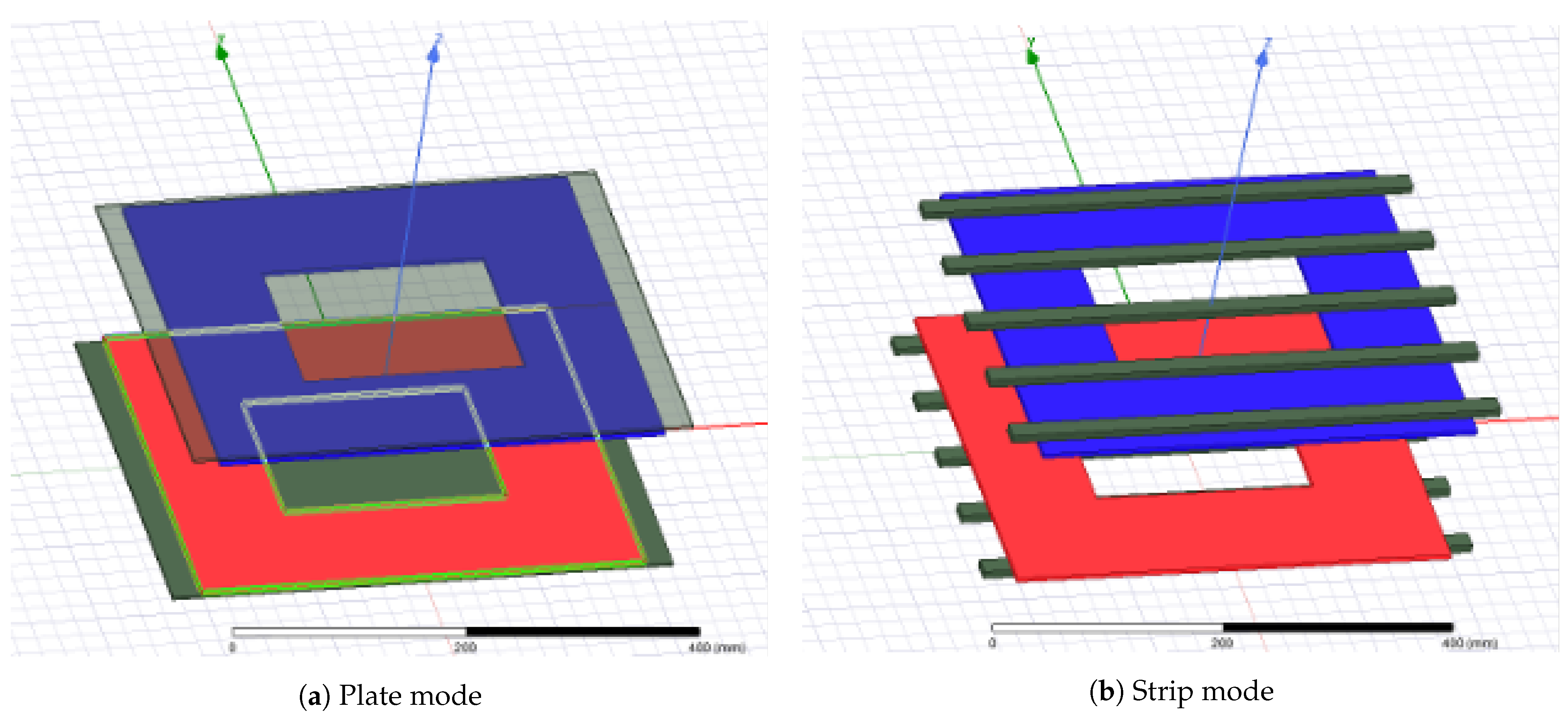
This study explores both the plate and strip ferrite structures’ effects. The FEM analysis for both structures is carried out using Ansys Maxwell software. The 3D models are shown in Figure 10.

Figure 10.
Plate ferrite vs. strip ferrite.
The size parameter setting in the simulation is listed in Table 4.

Table 4.
Parameter settings for ferrite structure simulation.
In this study, the size of the individual strip ferrite is fixed at mm considering manufacturing progresses. Only the difference in strip number is discussed. The simulation result is shown in Table 5.

Table 5.
Simulation results of various ferrite structures.
A plate ferrite with a thickness of 3 mm has a similar weight to the array of 8 strips (+2.5%). In the meantime, the coupling coefficient is slightly higher (+3.3%). However, a large thin ferrite plate is fragile and expensive to manufacture in industrial applications. When the thickness of the plate is increased to 5 mm, the total mass is significantly increased (+66.7%), but the improvement in coupling coefficient is limited (+3.9%).
It is observed that as the number of ferrite strips increases, the coupling coefficient increases slowly. In a compromise with the coupling coefficient and the weight constraints on the hardware application, an array of 5 strips is selected in this study. The coupling coefficient is .
3.6. Summary on Magnetic Coupling Mechanical Structure Design
In this section, a comprehensive investigation is performed regarding the electromagnetic design of the magnetic coupling structure of a WPT system following the physical constraints of an IWM system. Based on the FEM results, a rectangular coil with ferrite in a strip array is selected for the final design. The parameters of the designed magnetic coupling structure are listed in Table 6.

Table 6.
Mechanical design of the magnetic coupler.
4. Circuit Modeling and System Analysis
In the WPT system, many parameters change dynamically during operation. An optimized WPT system should maximize the transmission power or transmission efficiency.
In the WPT application for IWM, the mutual inductance and the system load are two main parameters that change frequently. In the case of IWM, the change of mutual inductance frequently occurs since the position between the transmitter and receiver coils frequently changes. This is very different from the popular wireless charging environment. On the other hand, the load for the WPT system is the wheel-side battery and the IWM itself. When driving, the WPT load is affected by torque demand, road conditions, and environmental factors such as temperature.
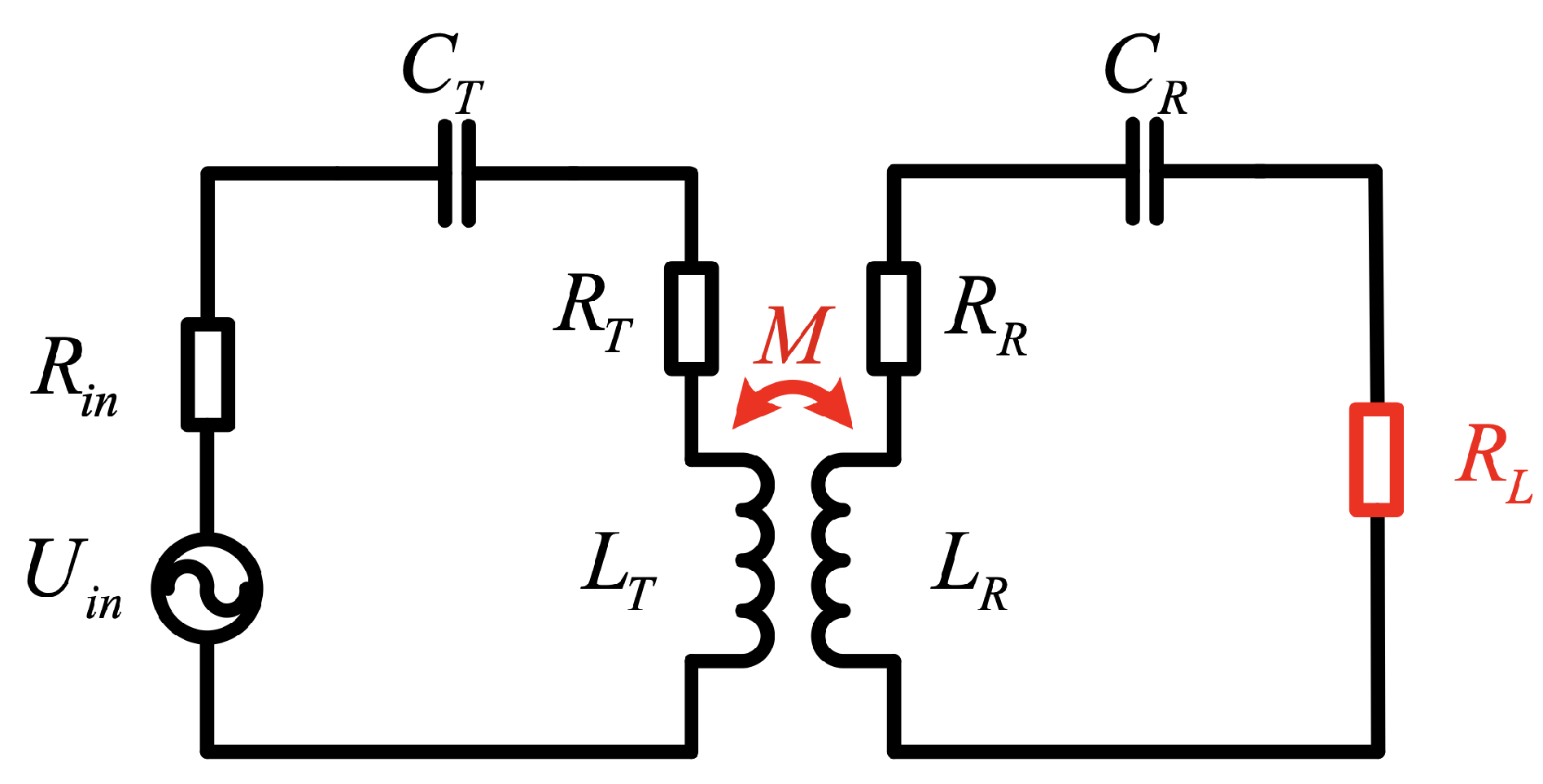
The system topology is shown as Figure 11.The internal resistance of the power supply at the input end of the system, the inductances , of the transmitting and receiving coils, the internal resistances , , and the resonant compensation capacitors , on the transmitting and receiving sides are determined parameters, and these parameters remain constant during the actual operation of the WPT system. Coil mutual inductance M and load impedance are dynamically changing parameters that change dynamically when the system is running, with the power supply internal resistance, and with the system frequency .

Figure 11.
Mutual inductance and load .
The current for the transmitter side () and receiver side is calculated as
The power on the receiver side is further calculated as
The system overall efficiency is calculated as
Influence of Dynamic Parameters
As introduced in the former section, the mutual inductance and the load are two main parameters that frequently change in an IWM–WPT system. In this part, their influences on the overall efficiency and transmitted power are discussed. The parameters applied for numerical analysis are listed in Table 7.

Table 7.
Electrical parameters of the designed WPT system.
According to engineering constraints, the maximum misalignment of the transmitter and receiver coils is defined as 25% of the horizontal height of the magnetic coupler. Thus, the variation interval for the mutual inductance is achieved with a FEM simulation. The values are listed in Table 8. The equivalent load resistance is set to a wider interval to emulate the actual working condition of an IWM.

Table 8.
The variation interval of and .
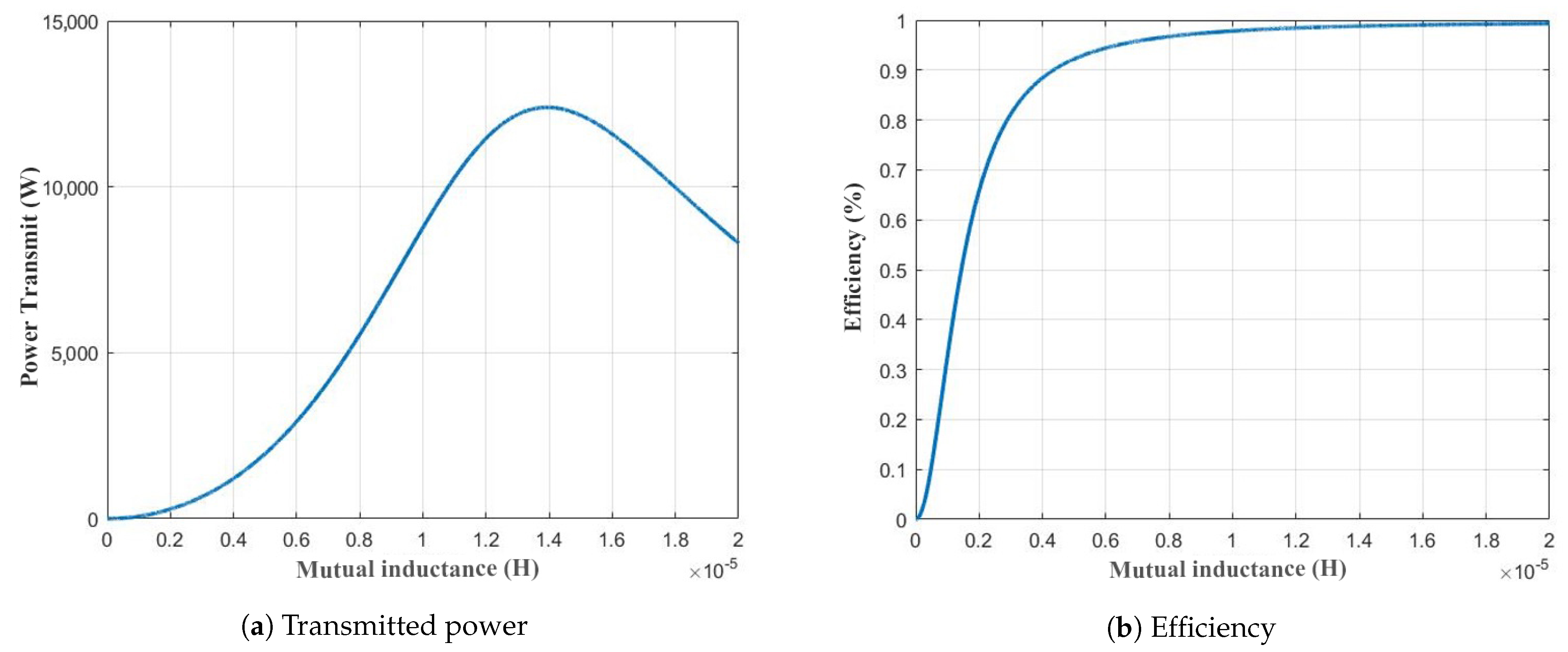
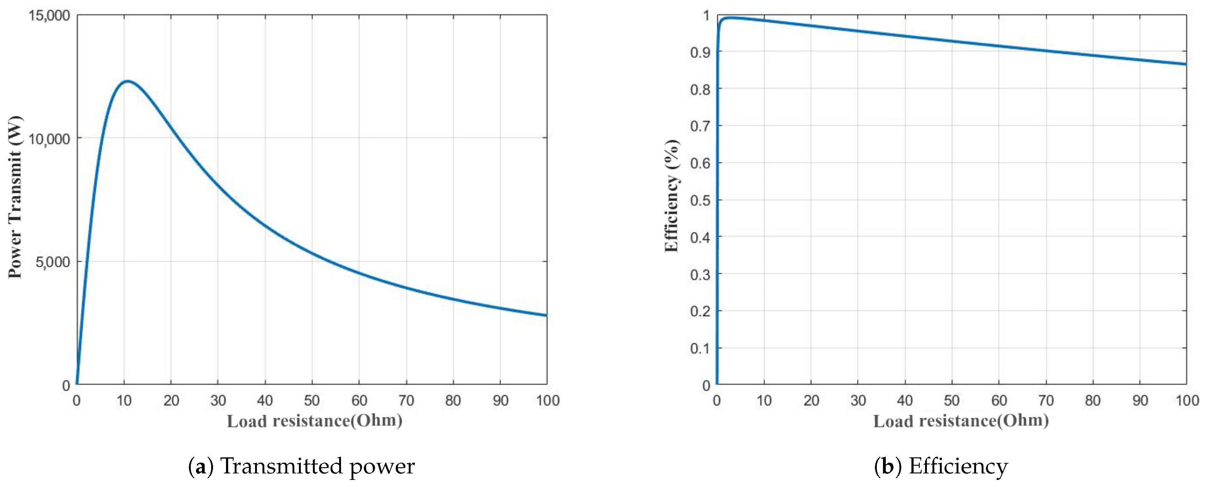
MATLAB software is used to conduct numerical calculation analysis and draw the transmission efficiency and power transmit curves of the WPT system when the dynamic parameters change, as shown in Figure 12 and Figure 13, respectively.

Figure 12.
The affect of various mutual inductance.

Figure 13.
The effects of various load resistances.
It is observed from Figure 12a that with the increase of the mutual inductance, the equivalent impedance of the system changes, and the power transmitted by the system would first increase and then decrease. From Figure 12b, the system efficiency increases with the increase of mutual inductance. However, the increasing rate becomes smaller as the mutual inductance grows. When the mutual inductance is above 10 µH, i.e., when the coupling coefficient is above 0.2, the system can reach a considerably high transmission efficiency of over 95%.
Figure 13 is the system transmission power and efficiency change curve with various load conditions. From Figure 13a, it can be seen that with the increase of the load equivalent resistance, the transmission power of the WPT system first increases and then decreases. The system transmits maximum power when the load is . It can be seen from Figure 13b that with the dynamic load change, the WPT system has been in a resonance state, and the electric energy is efficiently transmitted through the resonance coupler, i.e., the transmitter and receiver coils. The system transmission efficiency has been maintained in a high range until it suddenly decreases dramatically when the load is reduced to a particular value at around zero. It is assumed that this drop point is affected by the coil’s self-resistance.
5. Experiment Validation
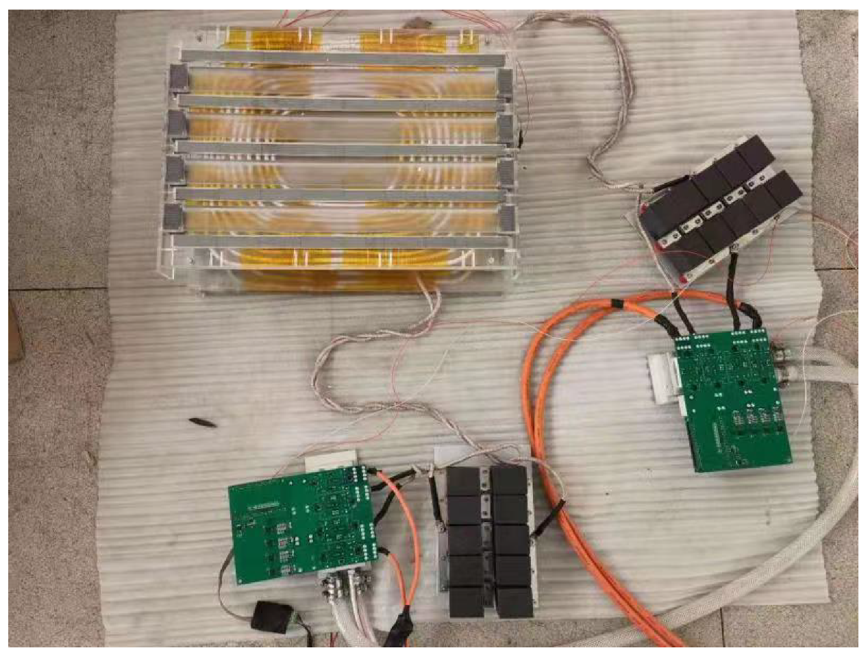
The designed WPT system is further verified with a full-scale prototype. The prototype’s mechanical and electrical parameters strictly follow the calculation and design in Section 2 and Section 3. The photo of the whole system is as shown in Figure 14.

Figure 14.
WPT system assembly.
5.1. Magnetic Coupling Structure
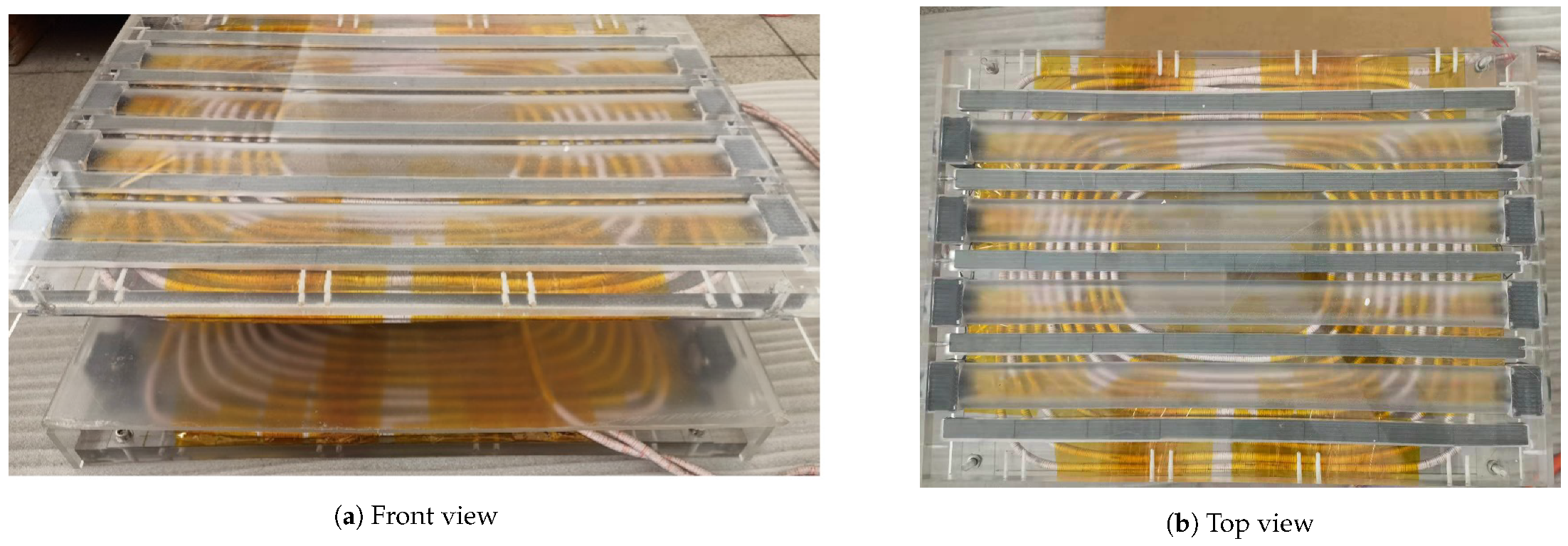
The prototype of the designed magnetic coupling structure is shown in Figure 15. The ferrite strips with a length of 480 mm in the design are fragile and complicated to manufacture. In this prototype, the ferrite strips consist of 8 ferrite strips of 60 mm in length each.

Figure 15.
Hardware photo of the magnetic coupling prototype.
The WPT system is designed to work under the frequency of 90 kHz. The coils are made with Litz wire to alleviate the skin effect caused by high frequency. The Litz wire applied has 1000 enamel-insulated wires with 0.1 mm diameter each. A translucent holder for the ferrite strips is designed with Polymethyl methacrylate (PMMA) material. Eight fans of 5 W each are installed along both sides of the ferrites for cooling purposes.
The self and mutual inductance of the magnetic coupling structure are measured by an LCR meter. We define the bottom coil as the transmitter and the top coil as the receiver. The measured values are listed in Table 9, with the inductance achieved from the FEM as a comparison.

Table 9.
Measured values of the magnetic coupler prototype.
5.2. Capacitors and Inverters
According to the measured inductance of the magnetic coupler prototype, the resonance capacitor parameter is designed as Equation (8).
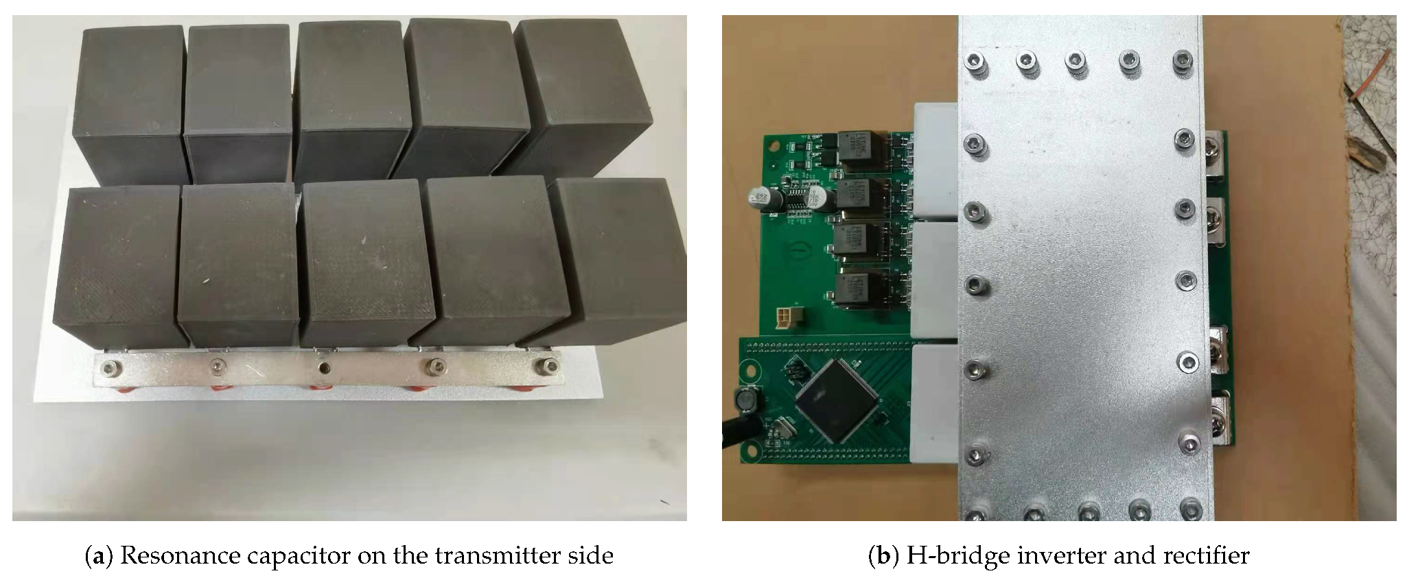
The capacitor module “ANWO SCM-3000-0.024-U5” is applied to this experiment. The capacitance of an individual capacitor is 0.024 µF. To meet the capacitance requirement as a resonance capacitor, 10 modules are applied and connected in a 5-parallel and 2-series way (shown in Figure 16a). In this way, the capacitance of the resonance capacitor module is 60 nF, while the voltage tolerance is over 3000 V. It is suitable for the designed WPT system.

Figure 16.
Capacitors and inverters.
The photo of the power electronic devices and the controller is shown in Figure 16b. The devices on the transmitter side and the receiver side are the same. The module uses “F4-23MR12W1M1B11” MOSFET from “Infineon”, the drain–source voltage is 1200 V, and the DC drain current is 50 A. The same power electric module as Figure 16b is applied as a rectifier on the receiver side. An electrolytic capacitor with a rated voltage of 1200 V and a capacitance of 220 µF is applied as the capacitor filter.
5.3. Experiment Results
5.3.1. Efficiency Test
The system input voltage is 300 V, and the system input current reading on the DC power source is A. Thus, the input power is calculated as kW. The output voltage at the DC load is 330 V, with a current of A, the power output is calculated as kW, and the system DC–DC efficiency can reach 90.2%.
5.3.2. Test under Misalignment and Load Changes
In the real-world case of an IWM–WPT system, the magnetic coupler’s performances under sudden load change and coupler misalignment are very important. In this part, the proposed IWM–WPT system is tested under such conditions.
For the misalignment test, the rectangular coil has moved 40 mm in the width direction (X direction in Figure 6b). The coupling coefficient measurement has changed from to after the change.
The test load uses a power DC load with variable resistance. In the load change test, the resistance has changed from to . Thus, the load is increased.
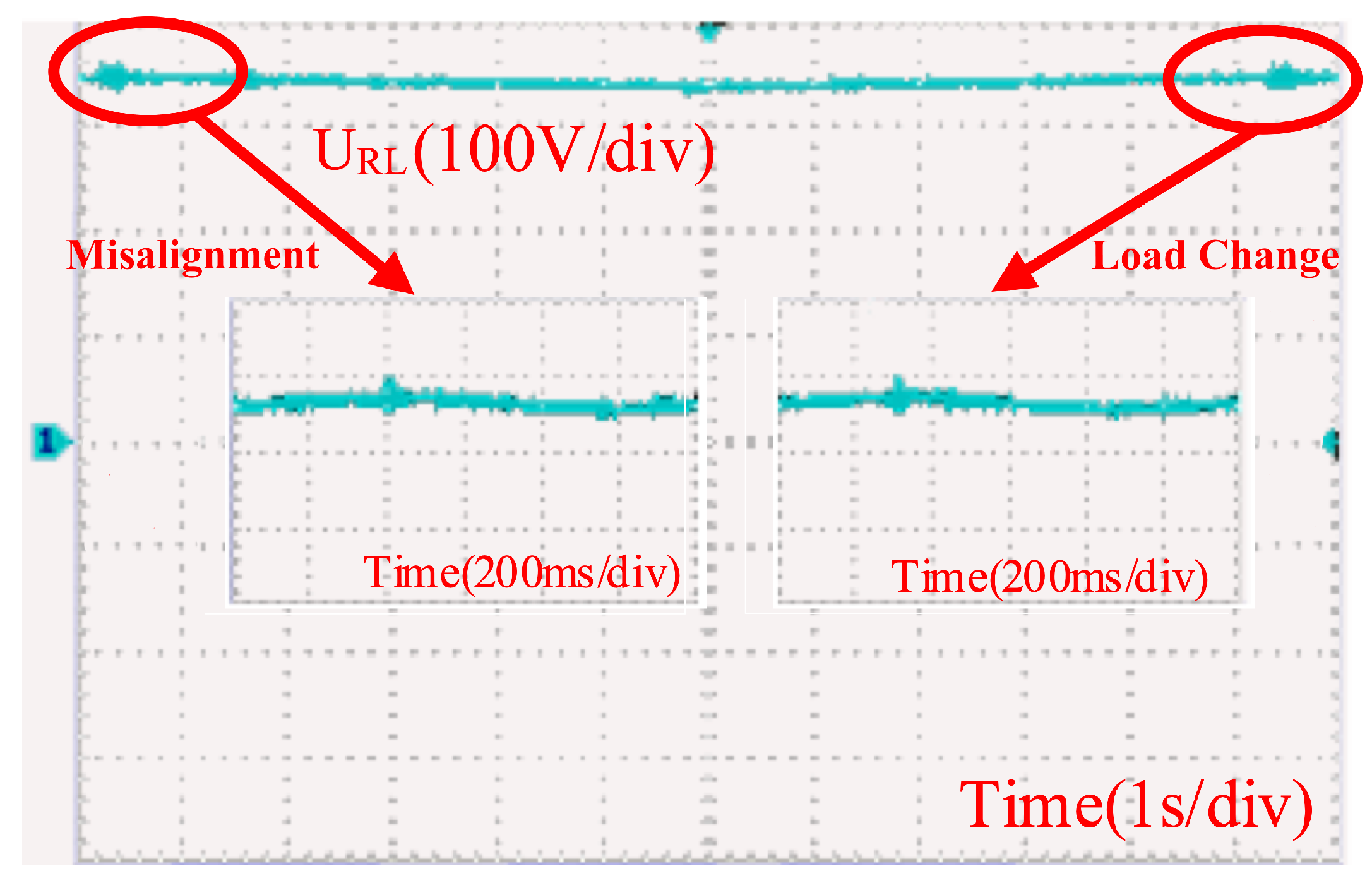
The voltage changes under load change and misalignment condition are shown in Figure 17, where is the rectified voltage on the DC load. The normal value of is constant at 330 V—the same as the design constraints in Table 1. The misalignment of coils and load change event occurred as shown at the beginning and end of Figure 17, respectively. The zoomed-in view shows that the voltage variations in both situations are minimal.

Figure 17.
Receiver voltage change.
The inverter output voltage on the transmitter side is shown in Figure 18. The operation frequency of the system is fixed at 90 kHz, while the dead-time setting in all three conditions is fixed at s. In normal operation, the system duty cycle is about . When the coils are under misalignment, the duty cycle increases to . When the load changes, the duty cycle increases to .

Figure 18.
Transmitter-side inverter output voltage.
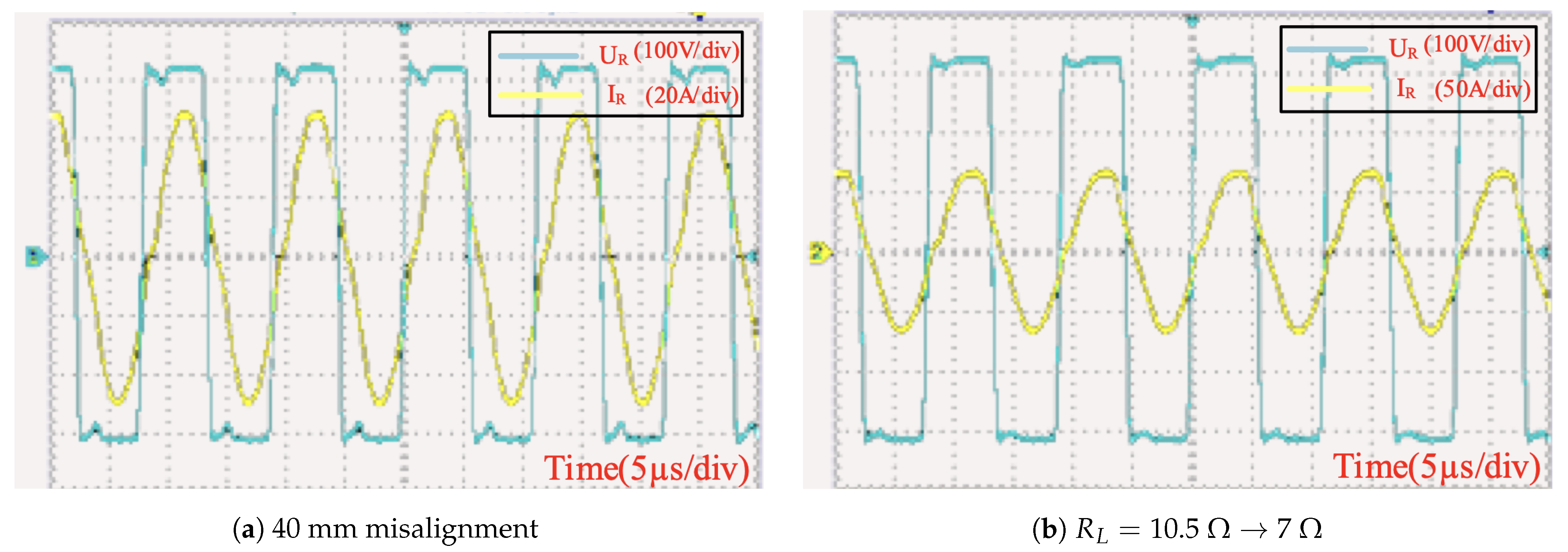
The experiment results of the WPT system receiver side outputs are shown in Figure 19. In Figure 19, the misalignment is 40 mm, the output voltage is 330 V, and the current peak is about 45 A (Figure 19a). After the load resistance is changed from to , the input voltage remains the same. The current increases to 65 A (Figure 19b). It is also observed in the figures that the series–series compensation network has the character of retaining the phase difference between voltage and current against load change.

Figure 19.
Receiver-side current and voltage.
6. Conclusions
This paper introduces the complete modeling procedure of a WPT system for the IWM application. The design notably illustrates two scenarios in IWM–WPT applications: coil misalignment and load change.
Misalignment between transmitter and receiver coils would affect the mutual inductance. This paper considers this influence in the design process of the magnetic resonance coupler by modeling and comparing the performance of three popular coil geometries. The FEM simulation results show that the rectangular coil has the best performance against coil misalignment regarding the coil size and interval constraints. Other essential designing aspects such as ferrite shape and coil coverage ratio are also discussed. Finally, a detailed list of parameters for an ideal magnetic coupler is presented.
Next, the influence of coil misalignment and load change on the system is explored. Following the system electrical parameters, numerical analyses of mutual inductance vary from 4 µH to 20 µH, and load equivalent resistance changes from to are provided.
Finally, the experiment results of a full-scale prototype are presented. The prototype follows the design parameters strictly, and the measured values of the inductance are very close to those found from the FEM. The experiment result shows that the designed WPT system successfully transmits over 10 kW of power between coil intervals of over 140 mm. The DC–DC efficiency is 90.2%. The output voltage is stable under 40 mm coil misalignment and over 50% load change scenarios, which proves that the designed WPT system is suitable for IWM applications.
Author Contributions
Conceptualization, Y.Z.; Methodology, J.Z., X.Z. and S.Z.; Software, J.Z.; Investigation, J.Z. and S.Z.; Writing—original draft, J.Z.; Writing—review & editing, J.Z., X.Z. and Y.Z.; Supervision, X.Z. and Y.Z.; Project administration, J.Z. and Y.Z.; Funding acquisition, Y.Z. All authors have read and agreed to the published version of the manuscript.
Funding
This work is supported by the National Key Research and Development Program of China (2021YFB2500900) and in part by the National Natural Science Foundation of China (51775039).
Acknowledgments
The authors would like to thank the reviewers for their corrections and helpful suggestions.
Conflicts of Interest
The authors declare no conflict of interest. The funders had no role in the design of the study; in the collection, analyses, or interpretation of data; in the writing of the manuscript; or in the decision to publish the results.
Abbreviations
The following abbreviations are used in this manuscript:
| DD | Double D |
| EV | Electric vehicle |
| FEM | Finite element method |
| IWM | In-wheel-motor |
| LCR meter | Inductance, capacitance, and resistance meter |
| MCRWPT | Magnetically coupled resonance wireless power transfer |
| PMMA | Polymethyl methacrylate |
| WPT | Wireless power transfer |
References
- Tesla, N. The transmission of electrical energy without wires. Electr. World Eng. 1904, 1, 21–24. [Google Scholar]
- Hui, S. Planar wireless charging technology for portable electronic products and Qi. Proc. IEEE 2013, 101, 1290–1301. [Google Scholar] [CrossRef]
- Patil, D.; Mcdonough, M.K.; Miller, J.M.; Fahimi, B.; Balsara, P.T. Wireless power transfer for vehicular applications: Overview and challenges. IEEE Trans. Transp. Electrif. 2017, 4, 3–37. [Google Scholar] [CrossRef]
- Ho, J.S.; Kim, S.; Poon, A.S. Midfield wireless powering for implantable systems. Proc. IEEE 2013, 101, 1369–1378. [Google Scholar] [CrossRef]
- Detka, K.; Górecki, K. Wireless Power Transfer: A Review. Energies 2022, 15, 7236. [Google Scholar] [CrossRef]
- Zhang, Z.; Pang, H.; Georgiadis, A.; Cecati, C. Wireless power transfer: An overview. IEEE Trans. Ind. Electron. 2018, 66, 1044–1058. [Google Scholar] [CrossRef]
- Wang, C.; Xu, W.; Zhang, C.; Wang, M.; Wang, X. Microwave wireless power transmission technology index system and test evaluation methods. EURASIP J. Adv. Signal Process. 2022, 2022, 16. [Google Scholar] [CrossRef]
- Zhang, Q.; Fang, W.; Liu, Q.; Wu, J.; Xia, P.; Yang, L. Distributed laser charging: A wireless power transfer approach. IEEE Internet Things J. 2018, 5, 3853–3864. [Google Scholar] [CrossRef]
- Dang, K.; Zhang, J.; Zhou, H.; Huang, S.; Zhang, T.; Bian, Z.; Zhang, Y.; Wang, X.; Zhao, S.; Wei, K.; et al. A 5.8-GHz high-power and high-efficiency rectifier circuit with lateral GaN Schottky diode for wireless power transfer. IEEE Trans. Power Electron. 2019, 35, 2247–2252. [Google Scholar] [CrossRef]
- Coca, E. Wireless Power Transfer: Fundamentals and Technologies; BoD–Books on Demand: Norderstedt, Germany, 2016. [Google Scholar]
- Lu, F.; Zhang, H.; Mi, C. A review on the recent development of capacitive wireless power transfer technology. Energies 2017, 10, 1752. [Google Scholar] [CrossRef]
- Covic, G.A.; Boys, J.T. Inductive power transfer. Proc. IEEE 2013, 101, 1276–1289. [Google Scholar] [CrossRef]
- Geng, Y.; Li, B.; Yang, Z.; Lin, F.; Sun, H. A high efficiency charging strategy for a supercapacitor using a wireless power transfer system based on inductor/capacitor/capacitor (LCC) compensation topology. Energies 2017, 10, 135. [Google Scholar] [CrossRef]
- Kurs, A.; Karalis, A.; Moffatt, R.; Joannopoulos, J.D.; Fisher, P.; Soljacic, M. Wireless power transfer via strongly coupled magnetic resonances. Science 2007, 317, 83–86. [Google Scholar] [CrossRef] [PubMed]
- Liu, X.; Hui, S. Optimal design of a hybrid winding structure for planar contactless battery charging platform. IEEE Trans. Power Electron. 2008, 23, 455–463. [Google Scholar]
- Luo, Z.; Wei, X. Analysis of square and circular planar spiral coils in wireless power transfer system for electric vehicles. IEEE Trans. Ind. Electron. 2017, 65, 331–341. [Google Scholar] [CrossRef]
- Ridge, A.; Ahamad, K.K.; McMahon, R.; Miles, J. Development of a 50 kW wireless power transfer system. In Proceedings of the 2019 IEEE PELS Workshop on Emerging Technologies: Wireless Power Transfer (WoW), London, UK, 18–21 June 2019; pp. 406–409. [Google Scholar]
- Lau, K. Comparative Study of Different Coil Geometries for Wireless Power Transfer. Ph.D. Thesis, Universiti Teknologi PETRONAS, Seri Iskandar, Malaysia, 2016. [Google Scholar]
- Wen, H.; Zhang, C. Investigation on transmission efficiency for magnetic materials in a wireless power transfer system. In Proceedings of the 2015 IEEE 11th International Conference on Power Electronics and Drive Systems, Sydney, Australia, 9–12 June 2015; pp. 249–253. [Google Scholar]
- Ahmad, A.; Alam, M.S.; Chabaan, R. A comprehensive review of wireless charging technologies for electric vehicles. IEEE Trans. Transp. Electrif. 2017, 4, 38–63. [Google Scholar] [CrossRef]
- Liu, C. Emerging electric machines and drives-An overview. IEEE Trans. Energy Convers. 2018, 33, 2270–2280. [Google Scholar] [CrossRef]
- Sato, M.; Yamamoto, G.; Gunji, D.; Imura, T.; Fujimoto, H. Development of wireless in-wheel motor using magnetic resonance coupling. IEEE Trans. Power Electron. 2015, 31, 5270–5278. [Google Scholar] [CrossRef]
- Jiang, C.; Chau, K.T.; Lee, C.H.; Han, W.; Liu, W.; Lam, W. A wireless servo motor drive with bidirectional motion capability. IEEE Trans. Power Electron. 2019, 34, 12001–12010. [Google Scholar] [CrossRef]
- Wang, H.; Chau, K.; Lee, C.H.; Cao, L.; Lam, W.H. Design, Analysis, and Implementation of Wireless Shaded-Pole Induction Motors. IEEE Trans. Ind. Electron. 2020, 68, 6493–6503. [Google Scholar] [CrossRef]
- Jiang, C.; Chau, K.; Liu, C.; Han, W. Design and analysis of wireless switched reluctance motor drives. IEEE Trans. Ind. Electron. 2018, 66, 245–254. [Google Scholar] [CrossRef]
- Colussi, J.; Re, R.; Guglielmi, P. Modelling and Design of a Coils Structure for 100 kW Three-Phase Inductive Power Transfer System. Energies 2022, 15, 5079. [Google Scholar] [CrossRef]
- Yang, Y.; Cui, J.; Cui, X. Design and analysis of magnetic coils for optimizing the coupling coefficient in an electric vehicle wireless power transfer system. Energies 2020, 13, 4143. [Google Scholar] [CrossRef]
Disclaimer/Publisher’s Note: The statements, opinions and data contained in all publications are solely those of the individual author(s) and contributor(s) and not of MDPI and/or the editor(s). MDPI and/or the editor(s) disclaim responsibility for any injury to people or property resulting from any ideas, methods, instructions or products referred to in the content. |
© 2023 by the authors. Licensee MDPI, Basel, Switzerland. This article is an open access article distributed under the terms and conditions of the Creative Commons Attribution (CC BY) license (https://creativecommons.org/licenses/by/4.0/).

