Article

Research on Air Gap Magnetic Field Characteristics of Trapezoidal Halbach Permanent Magnet Linear Synchronous Motor Based on Improved Equivalent Surface Current Method

School of Mechatronic Engineering, Xi’an Technological University, Xi’an 710025, China
*
Author to whom correspondence should be addressed.
Energies 2023, 16(2), 793; https://doi.org/10.3390/en16020793
Submission received: 11 December 2022 / Revised: 31 December 2022 / Accepted: 9 January 2023 / Published: 10 January 2023

Abstract

:
Accurate analysis of the air gap magnetic field is the focus of research in the field of precision permanent magnet linear synchronous motors. In this paper, the two-dimensional air gap magnetic field of a secondary trapezoidal Halbach permanent magnet array coreless permanent magnet linear synchronous motor (PMLSM) was taken as our research object. On the basis of the equivalent surface current method, we proposed an improved equivalent analytical algorithm with a trapezoidal side length unit. The equivalent analytical model of the magnetic induction vector of the two-dimensional air gap was established, and the air gap magnetic field of the trapezoidal Halbach array coreless PMLSM was calculated. At the same time, we analyzed the influence of the bottom angle α of a trapezoidal permanent magnet equivalent width coefficient αw, pole height coefficient αh, and air gap height coefficient αg on the amplitude (Bpeak) and total harmonic distortion (THDB) of the central magnetic field in the air gap. The results show that α and αw have a significant influence on the Bpeak and THDB of the central magnetic field air gap. With the synergy of α and αw, we identified the “flux convergence” effect, which makes the maximum range of Bpeak α > 90° and αw < 0.5. We also found the “equilateral” effect, which causes the minimum region of THDB to change linearly. The calculation results of the improved equivalent surface current analytical model established in this paper agree with those verified by the finite element method. The calculation is convenient, and the accuracy of the result is high. This research provides a new method for analyzing the air gap magnetic field of a permanent magnet with a nonrectangular cross-section and lays a theoretical foundation for optimizing the PMLSM pole model.

1. Introduction

PMLSMs have the advantages of a simple structure, large thrust density ratio, high efficiency, and accurate positioning, among others. It is increasingly used in precision and ultraprecision servo drive systems [1,2,3]. The coreless PMLSM has zero slot effect, zero positioning force, and smooth motion because it does not affect the slot and end effect. Because of the unique structure of coreless PMLSMs, the motor thrust is low. The currently established method for increasing the motor thrust uses a Halbach array. However, the shape and arrangement of permanent magnets have a greater impact on the air gap magnetic field of coreless PMLSMs. The distribution of the air gap magnetic field plays a decisive role in the strength of the motor’s thrust fluctuation [4,5]. Therefore, accurate analysis of the air gap magnetic field of coreless PMLSMs and the study of the Bpeak change and THDB of the air gap central magnetic field with Halbach array permanent magnet structure are of great interest in the PMLSM research.
At present, the numerical method represented by the finite element method is most frequently used to calculate complex boundaries, multiple media, and nonlinear problems. However, the preprocessing and calculation of the finite element method is time-consuming and generally used to verify electromagnetic performance after determining various size parameters. Some scholars have studied the air gap magnetic field using the equivalent magnetization, magnetic circuit, magnetic network, and surface current methods. Krop et al. calculated the no-load air gap magnetic field of a PMLSM using an equivalent magnetization method. By optimizing the shape and size of the permanent magnet, the sinusoidal distribution of the no-load air gap magnetic field of the motor was improved [6,7,8]. This method applies only to the solution of the electromagnetic field of a regularly shaped magnet whose boundary is parallel to the coordinate axis; the medium must be uniform, and the constraint condition that the magnetization direction is completely parallel to the direction of the coordinate system must be satisfied. Shei et al. used the equivalent magnetic circuit method to divide the magnetic field to be solved into several independent elements and calculate the magnetic conductivity of each element. They connected the nodes to form a magnetic network model in order to calculate the magnetic circuit and compare the calculation results in the finite element method [9,10]. The method is challenging when dealing with small structures. For example, when modeling the motor’s magnetic field, it is necessary to consider the small changes in the structure of the magnetic network caused by the changes in the primary and secondary relative positions. Liu et al. divided the motor into several independent units—magnetic fields—with uniform medium and regular geometry to calculate the equivalent magnetic conductivity. Because of the similarities between the magnetic and the electrical networks, the magnetic network is calculated by the node method, and the distribution of air gap magnetic density is obtained [11,12]. The method is problematic in solving the magnetic conductivity of adjacent nodes, as the amount of data calculated before and after the nodes move is large, and the calculation model lacks universality.
The equivalent surface current method is effective for calculating the magnetic field of a permanent magnet. The method treats the interior of the permanent magnet as a vacuum, and the magnetic field generated by the permanent magnet is equivalent to the magnetic field generated by its surface current layer. The method does not consider the complex calculation inside the magnet but converts the complex-shaped magnet into the current layer magnetic field calculation on its corresponding surface, effectively improving the calculation accuracy. Lee used the equivalent surface current method to analyze and calculate the PMLSM air gap magnetic field of the trapezoidal Halbach permanent magnet array and obtained the trapezoidal bottom angle that maximizes the motor thrust [13]. Xue et al. combined the equivalent surface current method with the subregion model and the magnetic field superposition principle and divided the permanent magnet motor into two subregion models for the analytical calculation of its magnetic field [14]. However, the calculation required to conduct the permanent magnet’s equivalent processing is extensive, resulting in the low analytical accuracy of the air gap magnetic field. Sun et al. also used the equivalent surface current method to treat the permanent magnet equivalently [15,16,17].
Some scholars have studied a permanent magnet linear synchronous motor with a rectangular permanent magnet structure. Boduroglu proposed three new coreless PMLSMs with a rectangular permanent magnet arrangement; analyzed the back EMF, air gap magnetic induction strength, and THDB of the motor; and experimentally verified the motor thrust and thrust fluctuation [18]. Ma proposed a single-layer concentric armature winding structure and analyzed and verified the secondary magnetic field composed of rectangular permanent magnets in the motor [19]. It can be seen from the above literature review that most research is focused on rectangular permanent magnets. The design scheme of trapezoidal permanent magnets changes the right-angle structure of traditional rectangular permanent magnets, resulting in the need to reconsider the influence of trapezoidal bottom angles in calculating the air gap magnetic field. Research on the influence of trapezoidal bottom angles on the Bpeak and THDB of magnetic fields in the air gap center of permanent magnet arrays whose bottom angle is not equal to 90° still needs to be completed. In addition, the analytical calculation method of the air gap magnetic field is greatly influenced by the geometric shape of the permanent magnet. When its shape is irregular and the magnetization direction is complex, the difficulty of using the traditional equivalent surface current method to calculate the air gap magnetic field is particularly evident; the method cannot reflect the internal characteristics of the real air gap magnetic field.
To sum up, in this paper, we establish an improved equivalent analysis algorithm based on the principle of the equivalent surface current method, with the trapezoidal side-length unit, in order to accurately calculate the air gap magnetic field of the trapezoidal Halbach permanent magnet linear synchronous motor and reveal the influence of the trapezoidal bottom angle α on the Bpeak change and THDB of the central air gap magnetic field. We study the bottom angle α of a trapezoidal permanent magnet, the equivalent width coefficient αw, the pole height coefficient αh, the influence of the air gap height coefficient αg on the Bpeak of the air gap’s center magnetic field, and the THDB.

2. Model of Improved Equivalent Analytical Algorithm

The trapezoidal Halbach array coreless PMLSM model studied in this paper is shown in Figure 1. In Figure 1a, the primary is the armature winding, and the secondary is the trapezoidal permanent magnet array. The trapezoidal permanent magnet array is mounted on the back yoke. The secondary structures on both sides of the motor are symmetrical and orderly. The difference between the magnetization directions of adjacent permanent magnets is 90°. Figure 1b is a two-dimensional structure diagram of the trapezoidal Halbach array coreless PMLSM model. The symmetrical Halbach array period is shown in the red box area in Figure 1b. The trapezoidal Halbach permanent magnet is symmetrical along the center of the vertically magnetized permanent magnet in a period. It is assumed that the vertically magnetized trapezoidal permanent magnet is the main magnetic pole, and the parallel magnetized trapezoidal permanent magnet is the auxiliary magnetic pole. In order to facilitate the establishment of the model, the derivation shown below sets the absolute coordinate system xoy based on the geometric center of the main magnetic pole.

3. Improved Equivalent Analytical Algorithm Modeling and Calculation Results

Assume the two-dimensional magnetic field of the air gap of the motor is as follows:
  • The secondary array of the motor is infinite along the z-axis;
  • The secondary magnetization of the motor is uniform;
  • The motor yoke is made of aluminum. In the calculation, the air, aluminum, and magnet permeability are taken as vacuum permeability.

3.1. Improved Equivalent Surface Current Method

By Biot–Savart’s Law:
d B = μ 0 4 π I d l × e r r 2
where e r is the unit vector, μ0 = 4π × 10−7 is the permeability in a vacuum, and r is the vector diameter from the source point (i.e., any point on I) to the p(x, y).
On the basis of the principal coordinate system established in Figure 1, take the horizontal left magnetized magnetic pole as an example and set a relative coordinate system xtotyt of each side of the left magnetized magnetic pole in the Halbach permanent magnet array period, as shown in Figure 2a. The center of the side length is ot, yt coincides with the side length, the included angle with M is an acute angle αvi, and xt is perpendicular to the side length, as shown in Figure 2b. Since the magnetizing direction of the magnetic pole is horizontal to the left, its surface current is composed of four sides (I, II, III, IV). Side IV is the equivalent of the current inflow, and the other three sides are the equivalent of the current outflow. Figure 2c shows the included angle αv1 between side length I and the magnetizing direction.
After the relative coordinate system xtotyt of any edge in Figure 2b is established, the magnetic field generated by the surface current edge I in the air gap magnetic field to any point p(xt, yt) in the air gap magnetic field can be obtained from Equation (1) and Figure 2c, as shown in Equation (2):
B i x t ( x t , y t , α v i , L ) = s i g n ( I ) M μ 0 cos α v i 4 π ln ( y t + L i / 2 ) 2 + x t 2 ( y t L i / 2 ) 2 + x t 2 B i y t ( x t , y t , α v i , L ) = s i g n ( I ) M μ 0 cos α v i 2 π [ arctan ( y t L i / 2 x t ) arctan ( y t + h / 2 x t ) ]
Sign (I) is a symbolic function, and the surface current I that flows out of the paper is +1; otherwise, it is −1. I is the serial number of the current side.
According to coordinate transformation, in the absolute coordinate system xoy, there are:
{ x t = ( x x 0 t ) cos α + ( y y 0 t ) sin α y t = ( x x 0 t ) sin α + ( y y 0 t ) cos α
Subsuming Equation (3) into Equation (2) to obtain the basic mathematical model of magnetic field calculation in an absolute coordinate system with side length as the unit is shown in Equation (4):
B i x t ( x , y , x 0 t , y 0 t , α v i , L i , α i ) = s i g n ( I ) M μ 0 cos α v i 4 π ln ( ( x x 0 t ) sin α i + ( y y 0 t ) cos α i + L i / 2 ) 2 + ( ( x x 0 t ) cos α i + ( y y 0 t ) sin α i ) 2 ( ( x x 0 t ) sin α i + ( y y 0 t ) cos α i L i / 2 ) 2 + ( ( x x 0 t ) cos α i + ( y y 0 t ) sin α i ) 2 B i y t ( x , y , x 0 t , y 0 t , α v i , L i , α i ) = s i g n ( I ) M μ 0 cos α v i 2 π ( arctan ( y y 0 t ) cos α i L i ( x x 0 t ) sin α i ( x x 0 t ) cos α i + ( y y 0 t ) sin α i arctan ( y y 0 t ) cos α i + L i ( x x 0 t ) sin α i ( x x 0 t ) cos α i + ( y y 0 t ) sin α i )
where αi is the angle between the relative coordinate and the absolute coordinate, (x0t, y0t) is the origin coordinate of the migration coordinate system, and Li is the side length of the calculated surface current.
When Equation (4) is introduced into Equation (3), the magnetic induction vector of the ith equivalent current edge in the absolute coordinate system at p(x, y) can be obtained, as shown in Equation (5):
{ B i x ( x , y , x i , y i , α v i , L i , α i ) = B i x t ( x , y , x i , y i , α v i , L i , α i ) cos α i B i y t ( x , y , x i , y i , α v i , L i , α i ) sin α i B i y ( x , y , x i , y i , α v i , L i , α i ) = B i x t ( x , y , x i , y i , α v i , L i , α i ) sin α i + B i y t ( x , y , x i , y i , α v i , L i , α i ) cos α i
Equations (3)–(5) calculate only the magnetic field generated by a single side length of the magnetic pole.
Assume that the included angle between the side close to the air gap center and the trapezoidal waistline is the bottom angle. For the trapezoidal Halbach permanent magnet array, the trapezoidal bottom angle is divided into 0 ≤ α ≤ 90° and 90° ≤ α ≤ 180°, as shown in Figure 3a,b. In Figure 3, the y-axis is the symmetrical center of the main magnetic pole, the x-axis is the center line of the air gap, h is the height of the permanent magnet, g is the height of the air gap, τ is the length of the magnetic pole distance, and the equivalent width w is the width of the main magnetic pole waistline.
For the universal research method, the model parameters are treated as dimensionless, and the feature length τ = 1 is introduced. The following three dimensionless pole structure coefficients can be obtained: for the equivalent width coefficient of trapezoidal magnet αw, take αw = w/τ; for the height coefficient of trapezoidal magnet αh, take αh = h/τ; and for air gap height coefficient αg, take αg = g/τ.
Figure 3 shows that the bilateral Halbach array of a single period has 24 sides in total. Therefore, from Equation (5) and the relationship between the coordinates αvi, Li, αi, and (xi, yi) of the midpoint of each current side, it can be shown that the magnetic induction vector generated by the trapezoidal Halbach permanent magnet array to p(x, y) in the air gap magnetic field is:
B x ( x , y ) = i = 1 24 B i x ( x , y , x i , y i , α v i , L i , α i ) B y ( x , y ) = i = 1 24 B i y ( x , y , x i , y i , α v i , L i , α i )
It can be seen from Figure 3 and Equation (6) that xi, yi, αvi, Li, and αi can be replaced by the four basic parameters α, αw, αh, and αg, and their expression is shown in Equation (7). For example, {± (τ − 0.5αw), ± τ, ± 0.5αw} is a set of xi, which takes αw as the variable.
{ x i ( α w ) { ± ( τ 1 2 α w ) , ± τ , ± 1 2 α w } ; x i , j = { x i ± 2 j τ } ; y i ( α g , α h ) { ± 1 2 α g , ± 1 2 ( α g + α h ) , ± ( 1 2 α g + α h ) } ; L i ( α w , α h , α ) { τ α w ± α h tan α , α h 1 + ( 2 / tan α ) 2 } ; α i ( α ) { ± ( π 2 + α ) , ± ( π 2 α ) , ± π 2 } ; ( 0 α π 2 ) α v i ( α ) { 0 , α , π 2 α } ; i = 1 , 2 , ...... , 24 j = 1 , 2 , ...... ,
To sum up, on the basis of the improved equivalent surface current method proposed by Equation (5), in this paper, first, the edges of each trapezoidal permanent magnet in the trapezoidal Halbach permanent magnet array are calculated equivalently. Then, the transformation relationship between the local and the global coordinate systems and the superposition principle is used to superimpose the magnetic fields generated by all the surface currents and finally obtain the complete and accurate air gap magnetic field distribution.

3.2. THDB Calculation Method

In this paper, the total harmonic distortion THDB [20] of the magnetic induction vector at the center of the air gap is taken as the characteristic quantity of the magnetic induction vector waveform sine at the center of the air gap:
T H D B = 1 B 1 n = 1 B 2 n + 1 2
where B2n+1 is the odd harmonic amplitude of the air gap magnetic density and B1 is the amplitude of the air gap magnetic density fundamental wave.
The amplitude of the magnetic induction vector at the center of the air gap in Equation (8) can be calculated by the Fourier transform of discrete periods.

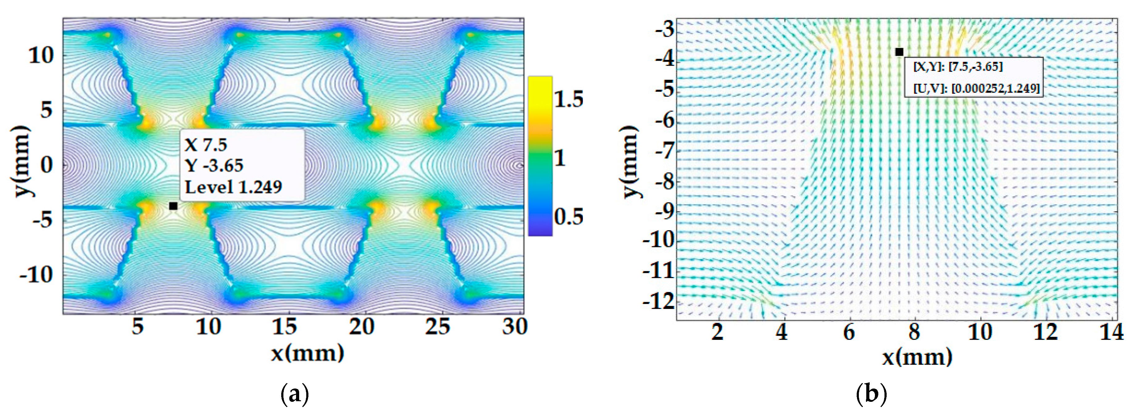
3.3. Calculation Results and Finite Element Verification

To verify the correctness of the improved equivalent surface current method, this paper takes the trapezoidal Halbach permanent magnet array model established in Figure 3 as an example and applies Equations (5)–(7) to analyze the By of the air gap’s center in the trapezoidal Halbach permanent magnet array model, where the bottom angle α is equal to 70° and 110°, respectively. The calculation results were also validated by the finite element method. The parameters of the trapezoidal Halbach permanent magnet array are shown in Table 1, and the calculation results are shown in Figure 4.
In Figure 4, when α = 70°, the Bpeak of By equals 0.7162 T. When α = 110°, the Bpeak of By is equal to 0.7367 T. The improved equivalent surface current method established in this paper and the finite element method have the same calculation results for the air gap magnetic field. The waveforms of the air gap magnetic density all show sinusoidal characteristics. The calculation results of the two methods deviate only slightly in the local waveform. With the simulation results as the benchmark, the maximum relative error is 0.031%.

4. Analysis of the Influence of Trapezoidal Bottom Angles α and αw, αh, and αg on the Air Gap Magnetic Field

On the basis of Figure 2 and Figure 3 as well as Equations (5)–(7), this section analyzes the influence of the changes in the bottom angles α and αw, αh, and αg on the air gap magnetic field in the ladder-type Halbach permanent magnet array model. The section explores the influence of various factors on the maximum value of the air gap central magnetic field amplitude Bpeak and the minimum value of the total harmonic distortion THDB. To ensure the universality of the calculation results, the following calculation parameters were selected: τ = 1, 60° ≤ α ≤ 120°, 0.3 ≤ αw ≤ 0.7, 0.3 ≤ αh ≤ 0.7, and 0.5 ≤ αg ≤ 0.9 (see Table 2 for detailed calculation and analysis scheme).

4.1. The Influence of α and αw on the Bpeak(α, αw) and THDB(α, αw) of Air Gap Central Magnetic Field

Bottom angles α and αw are variables with different αh and αg as parameters; the variation rules of the calculated air gap center magnetic field Bpeak(α, αw) and THDB(α, αw) are shown in Table 3. In the calculation area, Bpeak(α, αw) has a maximum point in the area of α > 90° and αw < 0.5, the relative change rate of Bpeak(α, αw) is about 2%, and the change rate near the maximum is lower. THDB(α, αw) have multiple minimum points, and the distribution of the minimum points changes linearly with the α and αw. It can be seen from Table 3 that increasing or decreasing αw has a significant influence on the distribution of the minimum of THDB(α, αw). The αh value affects the trend of the distribution of the minimum of THDB(α, αw) but does not change the shape of the distribution map of the minimum of THDB(α, αw). The αg value does not affect the trend of the distribution of the minimum of THDB(α, αw) but changes the shape of the distribution map of the minimum of THDB(α, αw).
In the PMLSM design, it is generally required that the thrust is large and the fluctuation is small; that is to say, the Bpeak is maximum and the THDB is minimum. It can be seen from Table 3 that under the coupling effect of the trapezoidal magnet bottom angle α and the three pole structure parameters αw, αh, and αg, αw has the strongest influence on the Bpeak and THDB, while αh and αg have only monotonic influence on the Bpeak and THDB. The higher αh is, the greater the air gap magnetic field strength is. However, when αh > 0.75, the enhancement of the air gap magnetic field strength is significantly slowed down. The smaller αg is, the greater the air gap magnetic field strength is, but the reduction range of αg is restricted by the thickness of the primary coil; αh and αg have little effect on the air gap central magnetic field THDB. The accurate analysis of the influence mechanism of α and αw on the Bpeak and THDB of the air gap central magnetic field is the basis for the correct selection of the trapezoidal magnet’s structural parameters.

4.2. Analysis of Influence Mechanism of α and αw on the Bpeak and THDB of Air Gap Central Magnetic Field

According to the analysis in Table 3, αw is the most significant factor affecting the Bpeak and THDB among the four structure parameters. The maximum Bpeak of the air gap center magnetic field is in the area where α > 90° and αw < 0.5, and the minimum area of the THDB changes linearly. This section was divided into three angles of α = 75°, 90°, and 105° taken as the calculation observation points with αw = 0.4, αh = 0.55, αw = 0.5, and τ = 15 mm. The improved equivalent surface current method was used to calculate and analyze the magnetic field distribution in the air gap–magnet yoke area and analyze the α and αw influence of on the Bpeak and THDB of the air gap center magnetic field. The calculation results are shown in Figure 5, Figure 6 and Figure 7, respectively. Figure 5a, Figure 6a and Figure 7a show the distribution of magnetic induction vector |B| in a period, and Figure 5b, Figure 6b and Figure 7b show the localized view of magnetic induction vector B.
It can be seen from Figure 5, Figure 6 and Figure 7 that if the auxiliary magnetic pole is magnetized transversely, the magnetic induction vector acts on the side of the main magnetic pole, thus strengthening the magnetic field intensity in the main magnetic pole, resulting in the effect that the magnetic field intensity inside the main magnetic pole is greater than that inside the auxiliary magnetic pole. Comparing the magnetic induction vector inside the main magnetic pole and the auxiliary magnetic pole in Figure 5a, Figure 6a and Figure 7a, it is found that when αw < 0.5, the magnetic field intensity inside the main magnetic pole is significantly higher than that inside the auxiliary magnetic pole, which constitutes the “flux convergence” effect of the magnetic induction vector. When αw is unchanged, α > 90° is conducive to the formation of “flux convergence” effect on the geometric structure when the magnetic induction vector in the main magnetic pole enters the air gap magnetic field. Compared with the observation points shown in Figure 5b, Figure 6b and Figure 7b, it is evident that the magnetic induction vector of the main magnetic pole is further improved.
In Figure 5, Figure 6 and Figure 7, the |B| value on the center line of the air gap changes periodically with its adjacent magnetic poles. The maximum or minimum value of |B| is obtained at the central position of the main magnetic pole, and |B| = 0 at the central position of the auxiliary magnetic pole. It can be seen from the periodic characteristics of harmonics that when the side lengths of the adjacent main and auxiliary magnetic poles at the air gap side are essentially the same, the THDB is smaller (referred to as the “equilateral” effect), achieving the standard sinusoidal waveform. Table 3 shows that when the side-length ratio of the adjacent air gap between the main and the auxiliary magnetic poles changes by one because of the shift in αh, it corresponds to the specific αh. When THDB reaches the minimum value, the side lengths of the main and the auxiliary magnetic poles in the adjacent air gap are not strictly equal.
The calculation results of the Bpeak and THDB of the center magnetic field of the air gap are shown in Table 4. When α = 105°, the magnetic induction vector in the main magnetic pole enters the air gap magnetic field to form a “flux convergence” effect in the geometric structure, and the magnetic induction vector of the main magnetic pole is the largest. When α = 75°, the side lengths of the main magnetic pole and the auxiliary magnetic pole near the air gap are approximately equal and the “equilateral” effect is noticeable, then the THDB is minimal.

5. Conclusions

In this paper, the characteristics of the air gap magnetic field of the coreless PMLSM of a trapezoidal Halbach array are studied on the basis of an improved equivalent surface current method. The main conclusions are as follows:
  • We present an improved equivalent surface current analytical algorithm for calculating the coreless PMLSM air gap magnetic field of a two-dimensional Halbach permanent magnet array, with the polygon side length as the element. This algorithm can fully reflect the internal characteristics of the real air gap magnetic field, and the calculation results are completely consistent with those of the finite element method, effectively proving the correctness of the new method;
  • Under the coupling effect of the bottom angle α of the trapezoidal magnet, αw, αh, and αh, αw is the most influential factor affecting the Bpeak and THDB among the three magnetic pole structure parameters, and αh and αg have only a monotonic effect on the Bpeak and THDB;
  • The maximum Bpeak value of the central magnetic field air gap is around α > 90° and αw < 0.5, and the minimum value of the THDB of the central magnetic field of the air gap changes linearly;
  • In the Halbach layout of the magnetic pole array, the “flux convergence” effect and the “equilateral” effect are the main factors influencing the area of the maximum Bpeak and the area of the minimum THDB.

Author Contributions

Conceptualization, B.L. (Bo Li), J.Z., X.Z., and H.D.; methodology, B.L. (Bo Li); software, J.Z.; validation, B.L. (Bo Li), J.Z., X.Z., and H.D.; formal analysis, B.L. (Bo Liu); investigation, B.L. (Bo Li); resources, H.D.; data curation, X.Z.; writing—original draft preparation, B.L. (Bo Li); writing—review and editing, B.L. (Bo Li); visualization, B.L. (Bo Liu); supervision, J.Z.; project administration, B.L. (Bo Liu) and J.Z.; funding acquisition, H.D. All authors have read and agreed to the published version of the manuscript.

Funding

This research was supported by the Natural Science Basic Research Plan in Shaanxi Province of China (2021JM-428), the Scientific Research Program Funded by Shaanxi Provincial Education Department (20JC016), the Xi’an Science and Technology Plan Project (22GXFW0048), the President Fund of Xian Technology and Business College (21YZZ04), and the Natural Science Basic Research Plan in Shaanxi Province of China (2023-JC-QN-0502).

Data Availability Statement

Not applicable.

Conflicts of Interest

The authors declare no conflict of interest.

References

  1. Baloch, N.; Khaliq, S.; Kwon, B. A high force density HTS tubular Vernier machine. In Proceedings of the IEEE International Magnetics Conference, Dublin, Ireland, 24–28 April 2017. [Google Scholar]
  2. Zhang, C.; Zhu, J.; Han, X. Rotor strength analysis of high-speed surface mounted permanent magnet rotors. Proc. CSEE 2016, 32, 4719–4727. [Google Scholar]
  3. Yao, Y.; Lu, Q. Comparative study of E-core and C-core modular PM linear machines with different slot/pole combinations. In Proceedings of the IEEE International Magnetics Conference, Dublin, Ireland, 24–28 April 2017. [Google Scholar]
  4. Wang, K.; Sun, H.; Zhang, L. An overview of rotor pole optimization techniques for permanent magnet synchronous machines. Proc. CSEE 2017, 37, 7304–7317. [Google Scholar]
  5. Tang, X.; Wang, X.; Sun, S. Analytical analysis and study of reduction methods of cogging torque in line-start permanent magnet synchronous motors. Proc. CSEE 2016, 36, 1395–1403. [Google Scholar]
  6. Krop, D.C.J.; Lomonova, E.A.; Vandenput, A.J.A. Application of Schwarz-Christoffel mapping to permanent magnet linear motor analysis. IEEE Trans. Magn. 2008, 44, 352–359. [Google Scholar] [CrossRef] [Green Version]
  7. Lee, J.H.; Song, J.Y.; Kim, D.W. Particle swarm optimization algorithm with intelligent particle number control for optimal design of electric machines. IEEE Trans. Ind. Electron. 2018, 65, 1791–1798. [Google Scholar] [CrossRef]
  8. Song, J.; Dong, F.; Zhao, J. An efficient multi-objective design optimization method for PMSLM based on extreme learning machine. IEEE Trans. Ind. Electron. 2019, 66, 1001–1011. [Google Scholar] [CrossRef]
  9. Sheikh-Ghalavand, B.; Vaez-Zadeh, S.; Hassanpour, I.A. An improved magnetic equivalent circuit model for iron-core linear permanent-magnet synchronous motors. IEEE Trans. Magn. 2010, 46, 112–120. [Google Scholar] [CrossRef]
  10. Du, Y.; Cheng, M.; Chau, K.T. Design and analysis of a new linear primary permanent magnet vernier machine. Trans. China Electrotech. Soc. 2012, 27, 22–30. [Google Scholar]
  11. Liu, G.; Jiang, S.; Zhao, W. Modular reluctance network simulation of a linear permanent-magnet vernier machine using new mesh generation methods. IEEE Trans. Ind. Electron. 2017, 64, 5323–5332. [Google Scholar] [CrossRef]
  12. Asfirane, S.; Hlioui, S.; Amara, Y. Global quantities computation using mesh-based generated reluctance networks. IEEE Trans. Magn. 2018, 54, 7002304. [Google Scholar] [CrossRef]
  13. Lee, M.G.; Gweon, D.G. Optimal design of a double-sided linear motor with a multi-segmented trapezoidal magnet array for a high precision positioning system. J. Magn. Magn. Mater. 2004, 281, 336–346. [Google Scholar] [CrossRef]
  14. Xue, Z.; Li, H.; Zhou, Y. Analytical prediction and optimization of cogging torque in surface-mounted permanent magnet machines with modified particle swarm optimization. IEEE Trans. Ind. Electron. 2017, 64, 9795–9805. [Google Scholar] [CrossRef]
  15. Sun, M.; Tang, R.; Han, X. Analysis and modeling for open circuit air gap magnetic field prediction in axial flux permanent magnet machines. Proc. CSEE 2018, 38, 1525–1533. [Google Scholar]
  16. Zhou, Y.; Lu, H.; Meng, G. Analytical calculation of magnetic field and cogging torque in surface-mounted permanent magnet machines accounting for any eccentric rotor shape. IEEE Trans. Ind. Electron. 2015, 62, 3438–3447. [Google Scholar] [CrossRef]
  17. Wu, L.; Yin, H.; Wang, D. A nonlinear subdomain and magnetic circuit hybrid model for open-circuit field prediction in surface -mounted PM machines. IEEE Trans. Energy Convers. 2019, 34, 1485–1495. [Google Scholar] [CrossRef]
  18. Deng, C.; Ye, C.; Yang, J. A Novel Permanent Magnet Linear Motor for the Application of Electromagnetic Launch System. IEEE Trans. Appl. Supercond. 2020, 30, 4902005. [Google Scholar] [CrossRef]
  19. Boduroglu, A.; Demir, Y. A Novel Track Structure of Double-Sided Linear PM Synchronous Motor for Low Cost and High Force Density Applications. IEEE Trans. Magn. 2021, 57, 8201305. [Google Scholar] [CrossRef]
  20. Ma, W.; Xi, L.; Zhang, Y. Design and comparison of linear induction motor and superconducting linear synchronous motor for electromagnetic launch. In Proceedings of the International Symposium on Linear Drives for Industry Applications, Wuhan, China, 1–3 July 2021. [Google Scholar]
Figure 1. Topology of coreless PMLSM for trapezoidal Halbach permanent magnet array: (a) topology diagram of motor structure, and (b) schematic diagram of the two-dimensional structure of trapezoidal Halbach permanent magnet array.
Energies 16 00793 g001
Figure 2. Schematic diagram of improved equivalent analytic algorithm modeling with trapezoidal side length as a unit: (a) horizontal left magnetization, (b) relative coordinate system established by side length, and (c) angle αv1 between side I and the magnetizing direction.
Energies 16 00793 g002
Figure 3. Analytical model of the modified equivalent surface current method for trapezoidal Halbach permanent magnet array: (a) 0 < α < 90° and (b) 90° < α < 180°.
Energies 16 00793 g003
Figure 4. Comparison of the improved equivalent surface current method and the finite element method results for the single-period air gap’s center magnetic field: (a) α = 70°, and (b) α = 110°.
Energies 16 00793 g004
Figure 5. Distribution diagram of air gap magnetic field (α = 75°): (a) distribution cloud diagram of |B| and (b) localized view of magnetic induction vector B.
Energies 16 00793 g005
Figure 6. Distribution diagram of air gap magnetic field (α = 90°): (a) distribution cloud diagram of |B| and (b) localized view of magnetic induction vector B.
Energies 16 00793 g006
Figure 7. Distribution diagram of air gap magnetic field (α = 105°): (a) distribution cloud diagram of |B| and (b) localized view of magnetic induction vector B.
Energies 16 00793 g007
Table 1. Structural parameters of THPMA.
SymbolQuantityValue
wthe equivalent width of a trapezoidal permanent magnet4.8 mm, 10.2 mm
hheight of trapezoidal permanent magnet9 mm
τpole pitch15 mm
gair gap height9 mm
Mmagnetization1.05 × 10 6 A/m
μ0permeability4π × 10−7 T·m/A
αbottom angle of trapezoidal70°, 110°
Table 2. Analysis scheme of the objective function and calculation parameters.
Objective FunctionCalculation Parameters
Bpeak(α, αw)
THDB(α, αw)
αg = 0.5αh = 0.5
αg = 0.5αh = 0.3
αh = 0.7
αh = 0.5αg = 0.3
αg = 0.7
Table 3. Analysis of the influence rule of α and αw on Bpeak(α, αw)and THDB(α, αw) of the central magnetic field of the air gap.
Calculation ParametersBpeak(α, αw)THDB(α, αw)
αh = 0.5, αg = 0.5
(Basic type,
Bpeak(α, αw) has a maximum value area, and the minimum value area of THDB is linear.)
Energies 16 00793 i001Energies 16 00793 i002
αh = 0.3, αg = 0.5Energies 16 00793 i003Energies 16 00793 i004
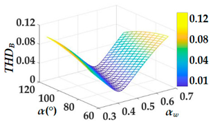
αh = 0.7, αg = 0.5
(The difference in αh affects the Bpeak and THDB trends.)
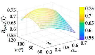
Energies 16 00793 i005Energies 16 00793 i006
αh = 0.5, αg = 0.3Energies 16 00793 i007Energies 16 00793 i008
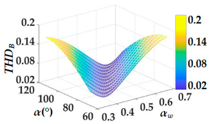
αh = 0.5, αg = 0.7
(The difference in αg affects the steepness of Bpeak and THDB.)
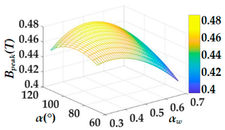
Energies 16 00793 i009Energies 16 00793 i010
Table 4. Calculation results of the Bpeak and THDB of the central magnetic field in the air gap.
αBpeak (T)THDB
75°0.87540.0136
90°0.90270.0475
105°0.92050.0687
Disclaimer/Publisher’s Note: The statements, opinions and data contained in all publications are solely those of the individual author(s) and contributor(s) and not of MDPI and/or the editor(s). MDPI and/or the editor(s) disclaim responsibility for any injury to people or property resulting from any ideas, methods, instructions or products referred to in the content.

