1. Introduction
Fresnel lenses are considered a promising option for solar energy concentration, due mainly to their low manufacturing cost and low weight, which promote mass production and modularity. Although the fundamental aspects have been presented previously in the literature [
1,
2,
3], there are still open issues, related not only to the design of the lens, but also the operational characteristics of integrated Fresnel lens collector-receiver devices [
4,
5,
6,
7,
8,
9].
A Fresnel lens is typically designed by cutting a parabola into small segments, otherwise referred to as “grooves” or “facets”, and these segments are translated onto a horizontal plane. This plane can represent the front or the back side of the lens; in most cases, it represents the back side, in order to avoid blocking of rays and weathering [
10,
11]. Compared to those refracted by the parabola, the rays refracted by the segments, even though they are not focused on a single point, but rather on a region, provide better concentration on the receiver and produce reduced longitudinal spherical aberration. Considering aberration in particular, spherical grooves can also be utilized towards its mitigation, while secondary optical elements are often incorporated with the aim of increasing optical efficiency and incident flux uniformity on the receiver [
12,
13,
14,
15].
Fresnel lenses are traditionally employed in applications involving the temperature increase in an HTF that passes through a piping system while receiving the incident flux. Zhai et al. [
16] studied a linear Fresnel lens collector used for concentrating solar power and increasing the temperature of water flowing through an evacuated tube. The experimental results indicated that a thermal efficiency of 50% could be achieved for the maximum inlet temperature tested, which remained below 100 °C due to it being the boiling temperature of water. Based on a simplified model, in which water was replaced with a synthetic oil, they concluded that changing the dimensions of the lens could result in similar values of energy efficiency for inlet temperatures equal to 200 °C. Lin et al. [
17] investigated the optical and thermal performances of a Fresnel lens collector combined with four different types of cavity. Heat loss measurements and predictions of a computational thermal model showed that, for a range of temperatures between 90 and 150 °C, the most efficient configurations involved triangular and the rectangular cavity receivers, which were able to reach efficiencies close to 70% and 60%, respectively. Point-focus Fresnel lens collectors, combined with a variety of coiled-tube cavity receivers, were studied by Xie et al. [
18,
19]. Analytical, computational, and experimental analysis was performed to assess the efficiency and the heat removal factor of various configurations for inlet temperatures ranging between 100 and 350 °C. The highest efficiency—reported to be close to 90%—was achieved when using the receiver with a conical cavity. Coiled-tube receivers with cylindrical, upright conical and inverted conical shapes were also investigated as independent systems, i.e., without a collector subsystem, by Awasthi et al. [
20]. Computational and experimental results for increased temperature, decreased pressure, and the Nusselt number have been reported for a range of mass flow rates. Heat transfer rates were discussed in relation to the heat transport area and the topology of the secondary flow within coils. The performance of a U-shaped solar energy collector was studied on the basis of experiments and computational modeling by Hussain and Lee [
21]. In this case, Fresnel lenses were utilized to concentrate the solar power at specific locations on the tubing, at which solar cells were placed. A parametric study was performed with the aim of identifying the optimum volumetric flow rate of HTF with respect to the increase in temperature, as well as the electrical and thermal power produced [
22]. Perhaps one of the most relevant studies in the literature with respect to the geometry considered in the present work is that presented by Xu et al. [
23]. Although they focused on a hybrid—not on a purely thermal—module, and used water for the HTF, meaning that the maximum temperatures were lower compared to those considered in the present work, that study presented a systematic assessment of the efficiency of the thermal component and the temperature increase as a function of inlet water temperature and mass flow rates.
Good reviews of receiver configurations widely used for thermal and photovoltaic applications can be found in [
24,
25]. However, our review of the literature showed that the assessment of the energy efficiency of purely thermal devices on the basis of systematic study of the effects of the design parameters, including the geometry, flow and thermal characteristics of the collector, along with possible alternatives that might potentially lead to improved energy performance, needs to be further extended. In this sense, the present study aims towards a parametric investigation of the operational characteristics of the collector, providing a contribution to the design of a specific device, either as an integrated unit or as a component of a modular configuration that, through the inter-connection of multiple units, might be capable of meeting thermal loads over a large capacity range.
In the present work, the performance of a small-scale solar energy concentrating device is studied, consisting of a Fresnel lens concentrator combined with a thin, flat-plate receiver with cylindrical channels carrying the HTF. The study includes the development of an MCRT model for the prediction of the values of optical efficiency of and incident flux to the receiver that fit the dimensions of the flat plate after refraction, as well as a CFD model for predicting the thermal efficiency of the device. The energy efficiency of the whole system is presented as a function of the inlet fluid temperature and the mass flow rate, which varies due to the different velocities imposed at the inlet, the change in the diameter of the cylindrical channels, and the overall size of the receiver. Scenarios under investigation also include the utilization of a selective coating on the absorbing surface of the receiver and the incorporation of an evacuated glass envelope, a configuration regarded as promising in high-solar-ray concentration systems, owing to the reduction in the amount of convection losses to the ambient.
The paper is structured as follows: First, a description of the physical model of the system is given. The design of the Fresnel lens is analyzed, and the equations used for the alignment of the grooves as a function of the distance from the focal point of the lens are reviewed. The details of the optical and thermal models are then presented. In the results section, the energy efficiency, the energy loss, and the energy absorbed by the HTF are discussed over a range of fluid temperatures and mass flow rates. The results are presented first for the reference scenario, for which solar radiation is concentrated to a rectangular receiver with a size of 10 cm with five cylindrical channels with diameters of 10 mm. Then, the results obtained for the alternative scenarios, which include the utilization of a selective coating on the top surface of the receiver, instead of painting it black, as initially considered, increasing the diameter of the channels to 15 mm, increasing the whole receiver size to 20 cm, and finally, utilizing a glass envelope in front of the top surface of the receiver, are reported. In all of these cases, the results are presented in combination with the benefits of utilizing the selective coating on the upper surface of the receiver. In the last section, the most important findings of the work are summarized.
2. Computational Modeling
2.1. Review of Fresnel Lens Equations
A typical Fresnel lens used for the collection of solar energy for thermal energy applications is presented in
Figure 1. The lens is designed as a thin flat sheet, consisting of concentric zones, accurately engraved on the initial flat surface. The size of the plate is equal to the lens diameter,
D. Solar rays vertically penetrate the front surface of the lens, change direction due to refraction from the back side, and, following a path dictated by the well-known Snell’s law, they are concentrated on the upper, absorbing surface of the receiver, at a distance
f, the focus of the lens. Concentrated solar power, in the form of heat, is conducted through the solid material of the receiver, and then it is transferred through conduction and convection to the HTF.
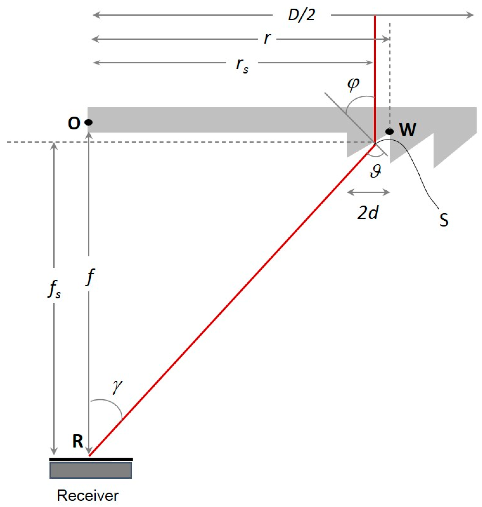
Typically, the design of the lens aims to: (i) achieve efficient concentration of solar power on the absorbing surface of the receiver; (ii) have a small depth of the prisms formed by the series of grooves at the back side of the lens, in order to diminish the amount of energy that is absorbed by the glass; (iii) optimize the weight and the material used for the lens; and (iv) eliminate solar power losses due to total reflection-related effects. With respect to the geometrical formulation,
Figure 2 is used for the estimation of the orientation of each groove in order for the solar rays that are refracted by the center of the groove to be directed to the focal point of the lens.
Rays arrive vertically with respect to the front (up) side of the lens, while they leave with the angle
φ, the angle between the line normal to the groove face and the horizontal line. Following Snell’s law, the refraction angle
θ is estimated using Equation (1):
With
rs and
fs being the horizontal and vertical distance between the “exit” point of the ray, S, and the focus, the following relationships can be used for the estimation of the angle
φ [
26]:
Angle
φ is a function of the location of point S, so that different angles can be estimated for the different points lying on the same groove. Since angle
φ is unique for the groove, it must be calculated based on a reference point, i.e., the center, and in this way, rays refracted by different points of the groove will follow parallel trajectories as they move towards the focus. This is the main source of aberration effects, which are dependent on the width of the groove and can be assumed to be insignificant in the case of very small groove sizes. For a groove length equal to 2
d, angle
φ is estimated using Equation (4):
The design of the lens is based on the following procedure:
- i.
Initially, the dimensions of the lens and the grooves width are defined, so that the distances of the centers of the grooves from the central symmetry axis can be estimated. The locations of the edges of the grooves are estimated by r = D/2 − i(2d), where i is the number of grooves moving towards the central axis.
- ii.
For every point W, angle
φ is calculated by utilizing Equation (4). The solution of this equation involves an iterative procedure. Assuming that groove semi-width w is very low compared to
f and, in most cases,
r, a simplified form of the equation can be utilized, i.e.,
- iii.
The calculations are repeated so that the orientation of the grooves moving towards the central axis is estimated until r ≤ 2d.
The combination of the angle
φ with the groove semi-width w is adequate to define the location and the orientation of the grooves. The most important limitation of the design is related to total reflection effects [
26]. With the aim of eliminating those effects, angle
θ should be kept lower that
π/2, otherwise:
Bearing in mind that the largest angles
φ are related to the outer edges of the lens, for
r = D/2, Equations (5) and (6) can be combined in order to estimate the (
D/
f)
max values, for which total reflection is eliminated.
Figure 3 illustrates the corresponding values as a function of the refractive index,
n, of the material used for the lens.
2.2. Physical Model
The Fresnel lens is grooved on a flat plate with dimensions 1 × 1 m
2. It produces a circular optical spot. Lens design is based on the equations described in the previous section, for a focus distance, lens diameter, and groove width of 1.2 m, 1 m and 5 mm, respectively. The lens material is a polymethyl methacrylate (PMMA), with a typical refractive index of
n = 1.49. The receiver is a perforated rectangular plate of steel with a size of 10 cm. The plate is drilled, and five cylindrical channels with a diameter of 10 mm are used for carrying the HTF. The upper surface of the receiver is located 1.08 m below the lens. This distance is somewhat lower than that of the focal point, since the aim is not to collect solar power at a single point, but rather to adjust the location of the receiver so that the optical spot is extended within its size boundaries. The dimensions of the receiver and the diameter of the channels are such that a significant amount of solar energy is first concentrated on the upper surface, and then is absorbed by the HTF. A black-painted absorbing surface is initially considered for the upper surface of the receiver. In order to simulate flow and thermal transport at medium temperatures, Therminol 66 with temperature-dependent properties is considered as the HTF [
27].
The initial geometry of the collector described above was defined by a preliminary study, performed in collaboration with a private industrial company aiming to develop the prototype and is considered to be the base-case scenario of the present work. The criteria involved the desired size of the collector that could ensure small weight, modularity, and flexibility, but also stability and robustness, considering also the adjustment of the support and the tracking mechanism. In the present work, the scenarios examined are used to analyze the means of improvement of the energy performance of the collector. These include the dimensions of the cylindrical channels and the entire receiver, whereby, in order for the optical spot to cover the upper surface of the receiver, the latter must be sized accordingly, a selective coating must be utilized instead of a black-painted surface, and the use of an outer glass cover could potentially contribute to a reduction in thermal losses to the ambient.
The scenarios examined in the present work involve two main receiver configurations, presented in
Figure 4. The first is based on a simple rectangular-shaped receiver with its upper surface exposed to the ambient. The second includes an outer glass surface above the upper surface of the receiver, while between the upper surface of the receiver and the glass, an evacuated space is considered. In this way, convection losses from the upper surface of the receiver are negligible, and only thermal radiation exchange occurs between this surface and the inner surface of the glass envelope. Convection and thermal radiation losses to the ambient are, in this case, considered to originate from the glass, instead of the solid steel.
In terms of heat transport, considering the first geometry, incident flux strikes the upper surface of the receiver and thermal power is transferred by conduction though the plate and then, through convection to the HTF. The temperature increase on the upper surface of the receiver causes energy losses, which are transferred to the ambient through convection and radiation. Considering the second geometry, the amount of the incident flux to the receiver is lower, since part of the energy is reflected and transmitted through the glass, while a small amount of it is also absorbed by the glass. Thermal power is then conducted through the plate before transferred to the HTF. Thermal radiation exchange occurs between the upper surface of the receiver and the inner surface of the glass while in this case, energy losses to the ambient are related to the glass, rather than the steel, temperature. In both the above scenarios, a selective coating is optionally applied to the upper surface of the plate. The low emissivity value of the coating is expected to contribute to the minimization of the energy losses to the ambient. The optical properties of the collector are summarized in
Table 1.
2.3. Optical Model
Based on the geometry of the physical model, an optical model was developed in SolTrace [
28]. SolTrace has been widely used for modeling incident flux distribution for a range of concentrated solar flux configurations [
29,
30,
31,
32]. Before its incorporation in the present work, SolTrace’s results were validated using Jeter’s measurement on parabolic trough collectors [
33]. SolTrace’s scripting environment was used to design a Fresnel lens by applying the series of grooves according to the equations presented in the previous paragraphs. Then, the refraction and convolution of rays towards the focal point of the lens were simulated by applying ray tracing. A pillbox distribution was used for the sun shape, while an optical error of 1.5 mrads was used for slope errors [
34].
A representation of the optical cone formed behind the lens is presented in
Figure 5. This figure was produced by utilizing planes as virtual stages at various locations below the lens. Since visualization is based on surface reconstruction by utilizing the rays that strike the various stages, a reversed cone is produced, having its top on the focal point of the lens. The number of rays that strike the receiver is used for the estimation of the incident flux distribution to the upper surface of the receiver. In the present work, simulations were performed for 3 million sun rays refracted by the lens. The uncertainty of the average flux that was estimated by SolTrace was less than 5%, while the successful rays ratio converged to 10
−4. A sensitivity study on the number of rays showed that further increase in the number of rays does not affect the results. An indicative incident flux distribution to the receiver for the reference is presented in
Figure 6.
2.4. Fluid–Thermal Model
The fluid–thermal model was developed in Ansys CFX [
35]. The governing equations include the mass, momentum, and energy conservation for the fluid (f) and the solid (s) phases. For the geometry and flow conditions examined in the present work, the Reynolds number ranged between 700 and 12,000. When the flow was considered turbulent based on the critical Reynolds number (2300) that was estimated by the inlet velocity, diameter and viscosity value for the specific inlet temperature, the standard k-epsilon model with typical constant values was used to resolve turbulent components. A scalable wall function was also utilized, which allowed arbitrary mesh refinement close to the walls independently of the Reynolds number of the fluid flow [
35].
Energy equation (fluid regions):
Energy equation (solid region):
Turbulent kinetic energy:
Turbulence dissipation rate:
The turbulent viscosity,
μt, is estimated as a function of production and dissipation rate, i.e.,
Τhe production of the turbulent kinetic energy,
Pk, is defined by
Four different configurations were developed for modeling the fluid flow and the heat transfer through the receiver. The first two, based on the simple geometry, where the upper surface of the receiver was, in the first case, considered to be painted black, while in the second it was a selective coating with different reflectivity and absorptivity values. Two additional configurations were based on a more complex geometry, where an outer glass surface was applied with the aim of reducing the energy losses to the ambient. In this case, to, a black-painted surface and a selective coating were considered for the upper surface of the receiver. In the case where the receiver was a simple perforated rectangular plate with micro-channels, six computational sub-domains were formed to represent the solid phase of the steel plate and each of the five channels which carried the HTF. Conduction was only solved in the solid phase, while in the fluid domains, the full set of Navier–Stokes and energy equations with convection terms was solved. The following zone properties and boundary conditions were applied to the model:
- i.
Solid plate: The plate was supposed to be made of steel. Steel properties are given as a function of temperature. Regarding, in particular, thermal conductivity, for a range between 100 and 200 °C, a representative value lies close to 50 W/m K. Adiabatic conditions were imposed at the back side and the peripheral walls. The non-uniform incident flux that was predicted by optical modeling was applied to the outer surface of the plate. A total heat transfer coefficient, given as a function of the temperature, was used for the estimation of both convection and radiation losses to the ambient;
- ii.
Heat transfer fluid (HTF): The heat transfer fluid was Therminol oil, with temperature-dependent thermal properties [
27]. At the inlet of the cylindrical channels, a uniform velocity was specified, with values varying between 0.25 and 1 m/s. Medium levels of turbulence, i.e., 5%, were applied to the inlet velocity. A zero-gradient condition was imposed at the outlet. In order to assess the performance of the system at the range of medium temperatures, uniform temperature values at the inlet varied between 100 and 200 °C.
When an outer glass surface and vacuum between the glass and the upper surface of the steel plate were considered, two additional computational domains were added. As for the boundary conditions concerning the HTF, these were similar to those used for the previous model. For the solid phase, due to the change in geometry, the boundary conditions were modified while additional boundary conditions were applied to the two domains used for the vacuum and the outer glass:
- i.
Solid plate: The upper surface of the plate was set as an interface, combined with a non-uniform incident flux, estimated by the product of the incident flux calculated by the optical model and the transmissivity of the glass. Adiabatic conditions were imposed at the back and the peripheral sides;
- ii.
Vacuum: Air at very low pressure was used to simulate the medium of the domains between the plate and the glass. The peripheral surfaces were considered to be adiabatic, while the upper and lower surfaces were interfaces, which ensured the conservation of energy through the boundaries;
- iii.
Glass envelope: The domain was characterized as solid glass with temperature-dependent thermal properties. The lower surface of the domain was set as interface. For the upper surface, a heat transfer coefficient as a function of the glass temperature was added as a user function. Regarding thermal radiation transport within the space between the upper surface of the plate and the inner glass surface, a surface-to-surface exchange was defined. Emissivity values were assigned to the inner surface of the glass envelope and the outer surface of the absorber, where the selective coating was located. The corresponding values were 0.15 and 0.93, respectively.
As already mentioned, a temperature-dependent heat transfer coefficient was applied as a parametric user function to account for both convection and thermal radiation from the receiver upper surface to the ambient. Considering thermal radiation, the flux is calculated by applying the well-known law of Boltzmann. The radiation heat transfer coefficient,
hrad, is estimated based on the known flux and the temperature difference between the solid surface and the ambient:
On the other hand, the natural convection coefficient,
hconv, was calculated based on the Rayleigh and the Nusselt numbers with temperature-dependent air viscosity,
ν, and thermal diffusivity [
36]:
In the above equation,
l is a characteristic length given by the ratio of the rectangular area of the upper surface of the receiver to the perimeter. For a given Rayleigh number, the Nusselt number that relates to the heat transfer coefficient is then calculated as:
The total heat transfer coefficient is finally calculated by the sum of the above coefficients.
The results of the heat transfer produced by the set of equations described above for the black-painted absorbing surface as well as the selective coating are presented in
Figure 7.
For the geometry of the reference scenario, a three-dimensional unstructured mesh of about 600,000 cells was used. Local refinement using layers inside and outside the walls of the cylindrical channels was applied. A parametric study based on the number of cells was performed. The results showed that for 20% finer meshes for the solid and fluid domains, the difference on the temperatures at the upper surface of the receiver and the outlets of the channels were less than 0.1 °C. The grid used for the simulations of the scenarios, i.e., without the outer glazing, is presented in
Figure 8, while representative contours of the temperature distribution on the top surface of the flat plate receiver, the temperature distributions at the central plane of the cylindrical channels and at two cross-sections, located 0.025 and 0.075 m from the inlets, are presented in
Figure 9.
CFX incorporates a pseudo-transient approach in a collocated grid towards convergence to the final, steady-state solution. In the present formulation, upwind schemes were used for the spatial discretization of the advection terms of the momentum and energy equations. Convergence criteria regarding the maximum and the RMS residuals of the momentum and the energy equation were set to 10−5. In addition, a 10−4 convergence criterion was applied to the imbalance of the energy equation at each of the individual domains of the computational model.
The computational model was validated by applying a uniform heat flux on the top surface of the receiver and comparing Nusselt number values produced by the present model to those produced by one of the most recent analytical expressions for uniformly heated pipe flow, for Reynolds numbers between 4000 and 12,000 [
37]. The results are presented in
Figure 10. Considering CFX results, the Nusselt number was estimated by the mean heat flux coefficient of the central cylindrical channel of the receiver and temperature dependent thermal properties, calculated at the mean Therminol temperature. The plot indicates relative deviations ranging between 20% and 1.2% for the lower and higher Reynolds numbers, respectively, which can be considered reasonable, taking into account the differences between the present geometry and that of the heated pipe flow.
3. Results and Discussion
The results presented in the following section refer to a range of scenarios described in the previous paragraphs. The results of the reference scenario are presented first, followed by those for the three alternative configurations, described in
Section 2.4. The performance of the system for the various conditions examined is characterized by the energy efficiency, which is defined by the ratio of the energy flux absorbed by the HTC to the incident flux on the surface of the lens. The absorbed energy is estimated by the difference between the incident flux to the receiver and the thermal losses from the receiver that are estimated by the optical and the CFD model, respectively. Due to the different absorptivity and emissivity values, the presence of the coating is expected to help reducing the thermal radiation to the ambient. Since, as will be shown, the coating affects substantially the energy efficiency, results obtained with its inclusion are also presented for all of the alternative configurations subsequently examined. Those include a receiver with cylindrical channels of larger diameter compared to the reference case, a receiver with larger overall dimensions, located at a distance such that the entire optical spot covers its surface and finally, a configuration equipped with an outer glass surface and vacuum between the upper surface of the receiver plate and the glass cover.
3.1. Reference Scenario
Results for the energy efficiency, energy loss and the area-weighted temperature of the upper surface of the receiver for the reference scenario are presented in
Figure 11A(a–c). The results are produced for inlet velocities varying between 0.1 and 1 m/s and inlet temperatures varying from 100 to 200 °C.
For the lower inlet velocities, it is interesting to note that the energy efficiency is significantly lower for fluid with lower inlet temperatures (
Figure 11A(a)). This trend is unlike what would be normally expected, since lower fluid temperatures lead, in general, to lower heat losses, and thus higher energy efficiencies [
24]. The low energy efficiency observed for the specific conditions can be explained by the weak heat transfer rate from the absorber to the fluid, which is a result of two different types of limitations: those associated with the weak heat transfer at the fluid–solid interface due to the low fluid velocity; and those related to the low overall thermal capacity of the fluid flow within the receiver. The amount of energy that is not transferred to the fluid does, in this way, contribute to the increase in the temperature of the receiver, before being ejected to the ambient as convection and thermal radiation losses. The results for the higher velocities, i.e., U = 0.75 and 1 m/s, indicate a different trend, although with no significant variations with different inlet temperatures. In this case, the increase in fluid temperature leads to slightly lower energy efficiency values, since energy losses increase, as expected, with temperature. The results indicate that the efficiency increases with the fluid velocity, but for the higher velocities examined, the values appear to reach a limit, and the curves tend to coincide. The above findings can also be justified based on the temperature distributions of the upper surface of the receiver (
Figure 11A(c)). As previously described, the lower fluid inlet velocities result in higher surface temperatures, and therefore, more significant losses. As for the effect of inlet temperature, for the lower velocities, the higher inlet temperatures lead to lower surface temperatures and thermal losses. With increasing inlet velocities, this trend is gradually reversed, albeit to a lesser extent. By summarizing the results of the reference scenario, and attempting to define the most efficient operational conditions of the system, it can be concluded that the latter are associated with inlet velocities greater than 0.75 m/s. For the specific velocity, the energy efficiency reaches values of around 0.8, without being substantially affected by the changes in the fluid temperature at the inlet. For further increase in velocity values, the gains in energy efficiency are not important.
3.2. Utilization of Selective Surface on the Upper Surface of the Receiver
The corresponding results for energy efficiency, energy losses and temperature in the case in which a selective coating is applied on the top surface of the receiver are presented in
Figure 11B(a–c), respectively. The trends characterizing the above variables are similar. Energy efficiency reaches and overcomes a value of 0.8 for velocities between 0.5 and 1 m/s. As expected, the utilization of the coating has a substantial effect on the reduction of energy losses; however, based on the relative increase in the energy efficiency for the various inlet velocities, indicatively estimated to be lower than 5% for U = 1 m/s and HTF inlet temperature 150 °C, it can be stated that the utilization of the coating is beneficial at temperatures close to 200 °C, and mostly for the lower inlet velocities examined.
3.3. Effect of Channel Diameter
In this section, the efficiency and the temperature of a receiver with channels of greater diameter than the reference configuration, i.e., 15 instead of 10 mm, are presented. The aim is to evaluate the effect of using a larger area for transferring heat to the HTF, considering in particular the low efficiency values reported when employing low velocities in the reference scenario. It should be noted that the velocity values are kept the same, and thus the overall mass flow rate in this case is accordingly higher.
The results are presented in
Figure 12A,B for the case of the black-painted upper surface and when using a selective coating on the upper surface of the receiver, respectively. The energy efficiency and the average temperature of the upper surface of the receiver for two different fluid velocities, i.e., U = 0.5 and 0.75 m/s, are presented compared to those in the reference scenario. The results at higher velocity, i.e., U = 1 m/s, are characterized by similar trends, although they are not presented in the plots. However, since the increase in the efficiency with the velocity is small in this range, the differences produced by the utilization of channels with larger diameters are less pronounced.
As expected, the larger area available for energy transfer to the HTF has a positive effect on the efficiency of the receiver. The increase in the efficiency is a result of the increase in the energy absorbed by the fluid, which is further supported by the increase in the Reynolds number owing to the increase in the channel diameter. Thus, a smaller amount of energy is available for increasing the temperature of the receiver, and due to the upper surface of the receiver having a lower temperature, the amount of energy loss also is also reduced.
Comparing the efficiency of the collectors with the black-painted surface and the selective coating, similar trends can be observed along with a slight systematic increase in values. Regarding surface temperature, when the selective surface is applied, higher values are to be expected, since the lower emissivity value of the coating limits energy losses to the ambient through radiation; thus, a greater amount of energy is available to heat the receiver.
Increasing the effective heat transfer surface area is considered a common practice in achieving increased efficiency in heat exchanging devices. However, in some cases, modifications influence the hydraulic equilibrium through the increase in the friction factor of the flow within the channel, leading to a significant drop in pressure. To evaluate the overall result, a Performance Evaluation Criterium (PEC) was used, defined as the ratio of the relative effect of change in heat transfer rate to the change in the friction factor. In addition, when comparing arrangements that differ in terms of both heat transfer and hydraulic configurations, the Thermal Performance Factor (TFP) was used, as defined by Equation (20) [
38,
39]:
where the dominator represents the PEC of the reference configuration, i.e., in the present calculations, the one with the smaller channel diameter.
The TPF values for two different temperatures and velocities, as well as for the black-painted receiver and that with the selective coating, are presented in
Table 2. The results verify that the receiver with the larger channels was characterized by a better overall performance, since all of the values presented here are greater than one. The most important benefits appear to be produced with lower mass flow rates (U = 0.5 m/s). When the selective coating is used for the receiver, the values stand close to each other, indicating that the benefits of the channels that were larger in diameter were similar, compared to the reference configuration.
3.4. Effect of Receiver Size
The results of scenarios involving a receiver with larger dimensions, i.e., 20 × 20 cm
2 instead of 10 × 10 cm
2, are presented in
Figure 13A. The energy efficiency, the energy losses and the receiver surface temperature of the reference configuration are also included in the plots. For the larger receiver, ten rather than five cylindrical channels with diameters of 10 mm are used for carrying the HTF, while inlet velocities are adjusted to maintain the mass flow rates, compared to those used for the original receiver dimensions.
The aim is to evaluate the potential of using a more compact configuration, which can be produced by reducing the distance between the lens and the receiver. Due to the smaller distance between the lens and the receiver, the degree of solar power concentration is smaller, and thus lower receiver temperatures are expected to occur, while, on the other hand, larger surface areas are available for heat exchange between the receiver plate and the HTF. In addition, by maintaining the mass flow rate, the Reynolds number of the flow is reduced, thus leading to lower heat transfer rates. Since the parameters described above affect the performance of the receiver in different manners, it was considered that their effect on the efficiency deserved a more detailed analysis.
Figure 13A(a) clearly shows that, despite the larger area available for heat transfer to the heat transfer fluid, the efficiency of the larger receiver reaches lower values compared to the reference case. The effect becomes more important for higher HTF temperatures; the relative reduction approaches 20% for 200 °C for both flow rates. In this case, a larger amount of energy loss is ejected to the ambient, due to the larger surface of the receiver, as indicated in
Figure 13A(b).
Figure 13A(c) reveals that, in this case, energy losses are not correlated with temperature. Even though the temperatures of the top surface of the receiver reaches lower values for the case of the larger receiver, the larger area is primary responsible for the increase in energy losses compared to the reference case, and eventually the decrease in energy efficiency, as previously described.
The corresponding results for the device with the larger receiver, considering the configuration with the selective coating, are presented in
Figure 13B(a–c). Similar observations to those discussed previously can be made. Perhaps the most interesting result is that related to the energy losses, which are reduced by 50% compared to those produced for the black-painted surface. However, since the amount of energy losses is particularly small in absolute values, only a slight increase in energy efficiency is observed compared to the reference configuration.
3.5. Utilization of an Outer Glass Surface and Vacuum
In this section, the effect of the glass envelope combined with an evacuated space between the upper surface of the receiver’s plate and the glass is reported. The results of energy efficiency, energy losses, i.e., the sum of optical and heat losses, and energy absorbed by the heat transfer fluid are presented in
Figure 14A(a–c). The corresponding results when a selective coating is used instead of the black-painted top surface of the receiver are also presented in
Figure 14B(a–c). Results involving two different mass flow rates, based on velocities of 0.5 and 1 m/s, are reported.
The utilization of glass envelopes is considered a standard strategy aiming to minimize convection losses and increase the energy efficiency of solar power receivers. However, when the amount of energy losses is particularly small, the transmissivity and the reflectivity of the glass reduces the amount of energy reaching the receiver. In this way, the benefits in terms of energy efficiency are not always those expected.
The plots indicate that when the outer glass envelope is used, the energy efficiency of the system decreases in all of the cases examined. The reduction is more important for U = 1 m/s, for which it reaches a maximum value of 5.5% when the inlet HTF temperature at the inlet is 125 °C. For a black-painted receiver surface, as well as for the selective coating, it is interesting to note that the incorporation of the glass leads to higher energy losses, and thus lower absorbing energy. Since the utilization of the glass leads to the opposite direction with respect to the improvement of the energy performance of the collector, a more detailed analysis of the losses, including optical ones, was attempted. This analysis showed that the major factor of losses is, indeed, optical ones, and not those produced by convection or thermal radiation. This statement can furthermore be supported by pointing out the particularly small differences in the results of energy losses reported for the black-painted surface and the selective coating, combined with the glass envelope.

 and
and 


