Article

A Hybrid Master–Slave Control Strategy for Multiple Distributed Generators in Microgrid

1
State Grid Beijing Electric Power Research Institute, Beijing 100075, China
2
Research and Development Department, TEMSTEC (Pvt) Ltd., Wah Cantt 47040, Pakistan
*
Author to whom correspondence should be addressed.
Energies 2023, 16(2), 968; https://doi.org/10.3390/en16020968
Submission received: 19 November 2022 / Revised: 28 December 2022 / Accepted: 4 January 2023 / Published: 15 January 2023
(This article belongs to the Topic Power Electronics Converters)

Abstract

:
The problem of insufficient regulation ability in isolated microgrid operations in traditional master–slave control is targeted in this research. A hybrid master–slave control strategy is proposed to operate multiple distributed generators (DGs) in a microgrid with alleviated regulation characteristics. Firstly, a virtual synchronous generator control is adopted in the master DG to provide voltage and frequency support for the system; however, the lack of participation of the slave DG control in traditional PQ droop control in the system regulation makes a master DG susceptible to any load variation. The problem is resolved by proposing an improved droop control strategy, which ensures that the slave DG has similar output droop characteristics as the master DG and thus can respond to system load disturbances alongside the master DG. Secondly, virtual coordinate transformation and virtual impedance control are introduced to realize the decoupling and precise distribution of output power of multiple DGs. Finally, a simulation and experimental platform for a multi-DGs parallel system are established to verify the effectiveness of the proposed strategy.

1. Introduction

With the rapid development of alternate energy power generation technology, microgrids that integrate distributed generators (DGs) such as wind turbines, photovoltaics, and energy storage have received extensive attention [1]. The grid-connected renewable energy generation is a flexible and reliable power electronic equipment for a microgrid, which helps to avoid the negative impact of the randomness and fluctuation of distributed power output on the power grid along with the improved energy utilization rate [2,3]. However, it is difficult to coordinate and control the output power among multiple power sources when the microgrid operates on an island. The realization of the coordinated control of multiple DGs in the microgrid is a significant guarantee to achieve the continuous and stable operation of the microgrid; while ensuring the high reliability of the system [4,5].
The control strategies of microgrid island operation are mainly divided into master–slave control [6] and peer-to-peer control [7]. Master–slave control refers to the difference between the master DG and the slave DG when the multi-power island is running. The master power supply adopts constant voltage source control to provide voltage and frequency support for the slave DG. The slave DGs can realize constant output power according to the external voltage–frequency reference irrespective of the number of slave DGs connected in parallel [8]. Therefore the master–slave control has a high dependency on the capacity of the master power supply; as a result, the regulation ability of the system is insufficient. To overcome the weak regulation capacity of a single master DG an adaptive power regulation mode was proposed to adjust the power output of the main control power supply by sacrificing part of the voltage and frequency amplitude [9]. The control solves the problem of a small adjustment ability of a single master DG device in traditional master–slave control. The effectiveness of the master–slave coordinated control strategy is verified in the simulation and experimental results in [10]. However, the single master DG has limited improvement effect on the system regulation ability and poor dynamic response effect. Expanding the master DG to several levels is proposed [11]. Based on introducing the improved droop control strategy, the power output of the master DG is coordinated to ensure the system’s long-term stable operation and the microgrid’s improved regulation ability. However, this method did not propose an improvement for the control structure of the master DG, and the power quality of the system was poor. Peer-to-peer control refers to the equal status of all DGs in the isolated microgrid operation. The constant voltage source control is adopted in the control structure, which can realize the “plug and play” control of multiple DGs [12]. A peer-to-peer control structure based on a traditional droop control strategy is proposed to adjust the power output of multiple DGs [13]. An improvement of the sharing of active and reactive power of the islanded microgrid based on load voltage control is proposed in [14]. However, the control structure is relatively complex and the system operation economy is poor. In [15], the operation economy of master–slave control strategy and peer-to-peer control strategy under the microgrid with the same load capacity is analyzed. The island operation simulation of the microgrid based on peer-to-peer control was established, and the improved droop control strategy was used to adjust the power output [16]. The precise power distribution was achieved by dynamically shifting the droop curve, but the control structure was relatively complex. The peer-to-peer control realizes power balance output based on the differential adjustment of multiple DGs but cannot recognize the economic operation of fluctuating power sources.
At present, the related problems of the control strategy of multiple DGs during the islanding operation of the microgrid have not been fully solved. It is difficult to balance the economy of microgrid island operation with the simplicity of the control structure. Compared with peer-to-peer control, master–slave control has a simple structure and is easily applied to the microgrid on a large scale. However, the traditional master–slave control strategy has some shortcomings, such as weak regulation ability and low reliability of local load power supply. To solve this problem, the paper proposes a hybrid master–slave control strategy for multiple DGs in a microgrid based on improved droop control to improve the shortcomings of the traditional master–slave control strategy, such as weak regulation ability and low reliability of local load power supply. The main contributions of this paper are summarized as follows:
(1)
For the slave DG using traditional PQ control, an improved droop control strategy is introduced to ensure that the slave DG has a droop output characteristic and can respond to load disturbances with the master DG. The master DG is controlled by a virtual synchronous generator (VSG) to provide voltage and frequency support for the power system.
(2)
Virtual coordinate transformation and virtual impedance control are introduced to realize decoupling and accurate distribution of output power of multiple DGs in a low-voltage microgrid.
The structure of this paper is as follows. In Section 2, the control structure of the master–slave microgrid is analyzed. Then, in Section 3, under the background of parallel operation of multiple DGs, virtual coordinate transformation and virtual impedance control are introduced. Moreover, the effectiveness of the proposed control strategy is verified by simulation and experiment results in Section 4 and Section 5, respectively. Finally, the conclusions are drawn in Section 6.

2. Topological Structure and Control Principle of Multi- DGs Hybrid Master–Slave Control

2.1. The Topology of the Multi-DGs Hybrid Master–Slave Control

The topology of the multi-DGs hybrid master–slave control studied in this paper is shown in Figure 1.
The three power sources (DG1, DG2, and DG3) supply power to the local or common load through their respective voltage source converters. The DC side is replaced by a voltage source udci(i = 1, 2, 3), and the AC side output realizes power transmission through the line impedance and switches after filtering out the high harmonics through the LC filter. A virtual synchronous generator controls DG1 as the master DG to provide voltage and frequency reference for the system. DG2 and DG3 are controlled by improved inverted droop control as the slave DG, which has droop regulation characteristics based on constant power output. The parameters of the slave DG are set in the same way to reflect the system regulation ability of the hybrid master–slave control structure.

2.2. Virtual Synchronous Generator Control

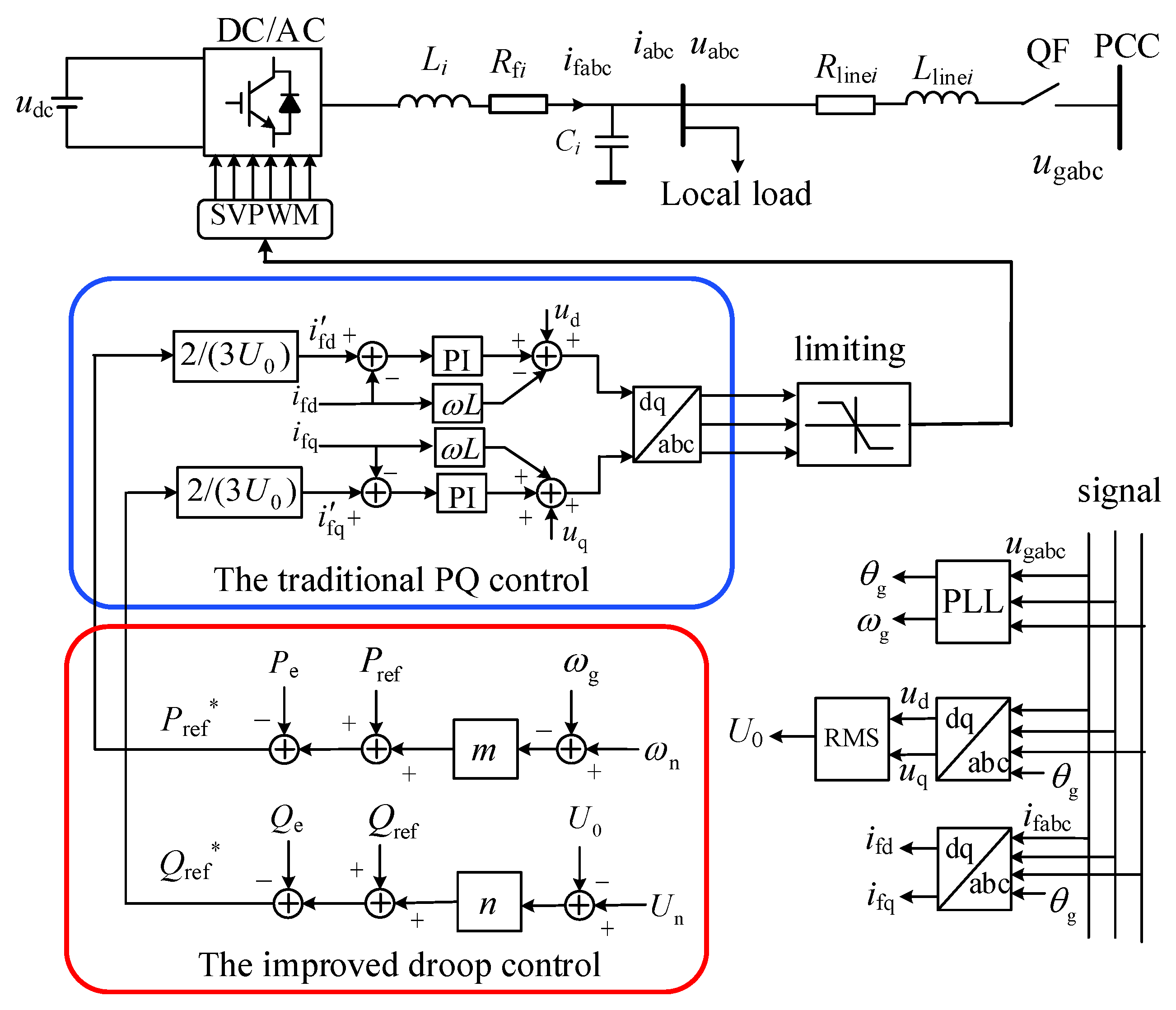
The power outer loop control structure of the master DG adopts a virtual synchronous generator, and the inner loop consists of voltage and current double-loop control. The detailed design of the outer and inner control loop of the master DG is shown in Figure 2. Where, the abc and dq modules represent the coordinate transformation of the system. Assuming the polar logarithm of the synchronous generator is one, and the mechanical angular velocity is consistent with the electrical angular velocity, the mathematical model of the VSG control loop can be expressed as follows:
{ J d ω d t = P ref ω n P e ω n D p ( ω ω n ) K d E d t = ( Q ref Q e ) + D q ( U n U 0 ) θ = ω dt  
In the formula: Pref and Qref are the given values of VSG active power and reactive power, respectively; Pe and Qe are the active and reactive power output by the VSG after the low-pass filter; Dp and Dq are the active frequency droop coefficient and reactive voltage droop coefficient; w and wn are the VSG output angular frequency and system rated angular frequency, respectively; E and θ are the potential amplitude and phase of the VSG control output, respectively; Un and U0 are the rated voltage amplitude and output voltage amplitude, respectively; J is the virtual moment of inertia; K is the equivalent inertia coefficient.

2.3. Improved Droop Control

To avoid the insufficient regulation ability of traditional master–slave control structures caused by a large-scale load disturbance, resulting in frequency and voltage sags, an improved droop control strategy based on traditional PQ droop control is proposed. It operates on a principle of synchronous generator’s primary regulation control and sets references accordingly. The slave DG also has the droop adjustment characteristic along with the master DG for regulating the power output, maintaining the load power balance, and ensuring the local load’s high-reliability power supply. The expression of the droop characteristic relationship between the active power and reactive power output from the slave DG is as follows:
{ ( ω n ω g )   m = P ref P e ( U n U 0 )   n = Q ref Q e
{ m = P max P e ω n ω gmax n = Q max Q e U n U 0 max
In the formula: ωg and U0 are the output angular frequency and voltage amplitude of the slave DG; m and n are the primary frequency modulation and voltage regulation coefficient of the slave DG, respectively; Pmax and Qmax are the maximum active power and reactive power output of the slave DG; ωgmax and U0max are the maximum value of the reference angular frequency and the maximum value of the reference voltage amplitude. The specific control structure is shown in Figure 3, where Pref* and Qref* are the reference value of the improved droop output active and reactive power.

3. Precise Power Distribution for Multi-DGs Hybrid Master–Slave Control

3.1. Virtual Coordinate Transformation

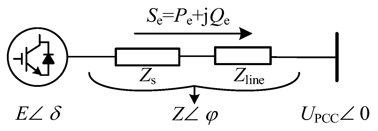
The schematic diagram of DG output power is shown in Figure 4, where: Eδ is the internal potential of the equivalent output of DG; Zs is the equivalent internal impedance; Zφ is the equivalent output impedance; UPCC∠0 is the voltage of the common connection point.
When considering the line impedance difference, the output power expression of DG is:
{ P e = 3 U PCC Z [ ( E U PCC ) cos φ + E δ sin φ ] Q e = 3 U PCC Z [ ( E U PCC ) sin φ E δ cos φ ]
When φ = π/2, the output power expression can be equivalent to:
{ P e = 3 U PCC E δ / Z Q e = 3 U PCC ( E U PCC ) / Z
It can be seen from the above formula that when the equivalent output impedance is inductive, the active power output Pe depends on phase δ, and the reactive power output Qe depends on the voltage deviation (E-UPCC), which meets the requirements of VSG or improved droop control. However, when φ ≠ π/2, the adjustment of DG output Pe and Qe will affect both the frequency and voltage amplitude, and there is a coupling relationship between power control. Therefore, when Z is not purely inductive, using VSG control or improving the droop control strategy will increase the power coupling and deteriorate the system’s stability.
Some experts proposed virtual coordinate transformation to solve the microgrid’s power coupling problem. It transforms the output power Pe and Qe into virtual power for system control [6]. The coordinate transformation matrix TPQ is:
[ P e Q e ] = [ sin φ cos φ cos φ sin φ ] [ P e Q e ] = T P Q [ P e Q e ]
Substituting (6) into (4), the following formula can be derived.
{ P e = 3 U PCC E δ / Z Q e = 3 U PCC ( E U PCC ) / Z
It can be seen from (7) that the one-to-one correspondence between virtual active power Pe’ and phase angle δ, virtual reactive power Qe’ and voltage deviation (E-UPCC) can be achieved through the coordinate transformation matrix TPQ, and then power decoupling is completed. Reference [6] gives a block diagram of virtual power decoupling control based on VSG control, which this paper will not repeat. The block diagram of the improved droop control based on virtual coordinate transformation is shown in Figure 5.

3.2. Virtual Impedance Control

The multi-DGs master–slave hybrid control in low-voltage microgrids also needs to solve the problem of accurate power distribution. Taking the dual-DGs parallel system in Figure 6 as an example, the effect of load power distribution between the master DG and the slave DG is analyzed.
When the system is in steady-state operation, the active power-frequency and reactive power-voltage control equations of the master DG and the slave DG are as follows:
{ D p ω n ( ω n ω A ) = P ref 1 P e 1 m ( ω n ω gB ) = P ref 2 P e 2
{ D q ( U 0 A U n ) = Q ref 1 Q e 1 n ( U n U 0 B ) = Q ref 2 Q e 2
Since the steady-state frequency is a global variable and remains equal everywhere, therefore setting ωgB = ωA, after sorting out the active power-frequency control equation, the following formula can be obtained.
D p ω n ( P ref 2 P e 2 ) = m ( P ref 1 P e 1 )
It can be seen from (10) that the distribution of load active power is only related to control parameters Dp and m when the droop coefficients Dp and m are set according to the capacity ratio so that the precise control of load active power can be achieved.
However, the voltage is not a global variable and is closely related to the line impedance, U0AU0B. The precise control of reactive power cannot be achieved by setting the control parameters. Aiming at the reactive power distribution error between DGs, virtual impedance control is introduced to account for the difference in line impedance, and then equivalent line impedance matching is achieved [17]. After introducing virtual impedance control, the voltage expression on the output side of the power supply is as follows:
{ U 0 A = U PCC + I 1 ( Z line 1 + Z v 1 ) U 0 B = U PCC + I 2 ( Z line 2 + Z v 2 )
After sorting out the reactive power-voltage control equation, the following derivation formula can be obtained.
n ( Q ref 1 Q e 1 ) = D q ( Q ref 2 Q e 2 )
From (12), it can be obtained that the reactive power distribution of multiple DGs can be precisely controlled after the introduction of virtual impedance control. When the system parameters are set in proportion to the capacity, the precise distribution of the reactive power of the common load can be achieved.

4. Simulation Results

To verify the effectiveness of the proposed control strategy, a multi-DGs parallel system platform, as shown in Figure 1, is built on Matlab/Simulink. DG1 is the master DG (Se1 = 10 kVA), which VSG controls; DG2 and DG3 are slave DG, which adopt improved droop control. The capacity ratio is 2:1:1 (Se2 = 5 kVA, Se3 = 5 kVA), and the specific simulation parameter settings are shown in Table 1.
To highlight the advantages of the multi-DGs hybrid master–slave control strategy proposed in this paper, it is compared with the traditional master–slave control strategy. The simulation duration is 4 s, and the operating conditions are set as follows. The common load (4 kW + j4 kVar) is initially supplied by the three DGs operating in parallel, and the slave DG adopts the traditional PQ control. When t = 0.5 s, the load suddenly increases; the common load changes to (6 kW + j5 kVar). When t = 1 s, the common load increases again and changes to (8 kW + j6 kVar). When t = 1.5 s, the slave DG adopts the improved droop control. When t = 2.1 s, the common load is put into (2 kW + 1 kVar). When t = 3 s, DG3 exits and DG1 and DG2 share the common load.
The schematic diagram of the multi-DGs master–slave hybrid control simulation output curve is shown in Figure 7. From Figure 7a,b, it can be seen that when VSG control + traditional PQ control is used, the slave DG only maintains a constant power output of 1 kW + 1 kVar, and does not participate in the regulating common load and the master DG fully bore the additional load. After implementing the proposed droop control strategy, the output power of master DG and slave DG meets the capacity setting of 2:1:1. When the load surge disturbance occurs, the slave DG output power supply also increases as per the capacity setting, thus achieving accurate power distribution and enhancing the regulation ability of the system. When the DG3 exits, the remaining power supplies can independently adjust the power output to ensure the high-reliability power supply of the load and the adjustment process is smooth.
Figure 7c,d are the waveforms of the output voltage and current of DG1. The analysis shows that the long-term stable operation of multiple DGs in a microgrid can be achieved when the proposed hybrid master–slave control strategy is applied in a microgrid.
Figure 7e,f are the waveforms of RMS voltage and system frequency at the common connection point. By comparing and analyzing the voltage and frequency changes of 2 kW + 1 kVar common connection points with load disturbance, it can be seen that when traditional PQ control is adopted, the voltage and frequency sags of the system are large, and the power quality is poor. However, with the introduction of improved droop control, the slave DG can also participate in the load power regulation of the system at the same time, reducing the voltage and frequency sags. The steady-state values of UPCC and output frequency are shown in Table 2. When t = 1.5 s, the slave DG applies the improved droop control strategy to participate in the system power output, and the ∆UPCC and ∆f are increased by 2.11 and 0.09, respectively. The comparative analysis shows that the system’s power quality is significantly improved when the control strategy proposed in this paper is adopted.

5. Experimental Results

The two-machine parallel experimental platform shown in Figure 8 is an example of experimental verification. Its experimental parameters are as follows. Vdc = 800 V; L = 0.6 mH; C = 15 uF; Zline1 = 0.2 + j0.3Ω; Zline2 = 0.3 + j0.4Ω; J = 0.15 (kg·m2); Zv2 = 0.1 + j0.2Ω; Dp = 4.4 or 8.8 (W/Hz); kf = 1.38 (kW/Hz); Dq = 0.4 or 0.8 (kVar/V); ku = 0.4 (kVar/V); Se1 = 10 (kVA); Se2 = 10 or 5 (kVA). Its switching frequency is 5 kHz. To verify the effectiveness of the proposed control strategy and parameter settings, local load-throwing and cutting experiments are conducted for different capacity DGs.

5.1. Two DG Capacity According to 1:1 Configuration

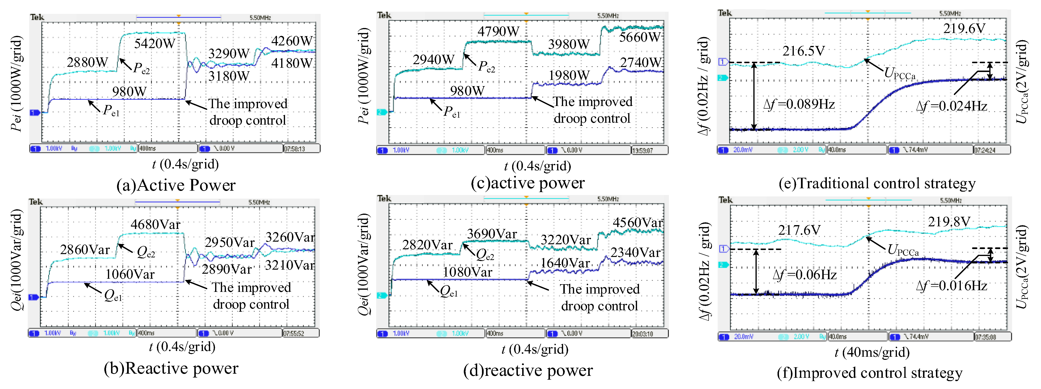
Figure 9a,b shows the power output waveforms when two DGs of the same capacity are operated in parallel. Initially, the two DGs use VSG control and PQ control to supply the local load of 4 kW + 4 kVar. A load surge of 2.5 kW + 2 kVar occurs at 1 s, switching traditional PQ control to improved droop control at 2 s, and the load increases to 8.5 kW + 6.5 kVar at 3 s. From the analysis of Figure 9a,b, it can be seen that when VSG control and traditional PQ control are used, the slave DG maintains a constant power output of 1 kW + 1 kVar and does not participate in system frequency regulation. The master DG fully assumes the remaining load. With the improved droop control strategy, the two DGs can realize power output according to the capacity ratio, and the load power equalization effect is remarkable. From the analysis of Figure 9c,d, it can be seen that similar to the parallel condition of DG with the same capacity, the slave DG with traditional PQ control maintains constant power output during load disturbance and does not participate in the load regulation of the system. When the slave DG applies the improved droop control strategy, it can increase the relevant output power according to the set capacity ratio, rather than maintain a constant.

5.2. Two DG Capacity According to 2:1 Configuration

Figure 9c,d shows the power output waveforms when two DGs of 2:1 capacity are operated in parallel. A 2 kW + 1 kVar load surge disturbance occurs at 1 s, and a 2.5 kW + 2 kVar surge disturbance occurs at 3 s. The rest of the experimental conditions are consistent with the parallel operation of the DG of the same capacity. With the introduction of the improved droop control strategy, the output power of the master DG and the slave DG meets the capacity setting of 2:1. The slave DG can also increase the corresponding power according to the capacity setting when a sudden load disturbance occurs, thus avoiding the phenomenon of voltage and frequency overrun caused by the load fluctuation borne by the master DG. The DG output power distribution results under different operating conditions are shown in Table 3 below. The analysis shows that the improved droop control strategy proposed in this paper can accurately realize the accurate control of the power between the master DG and the slave DG. It is consistent with the theoretical analysis results.
Figure 9e,f shows the common connection point’s voltage and frequency output waveforms when two DGs of 2:1 capacity are operated in parallel. A comparative analysis of voltage and frequency variations at the common connection point for load disturbance occurs at 1 kW + 1 kVar. When the disturbance of common load suddenly decreases, the values of ∆Upcca and frequency ∆f using improved droop control is 0.2 and 0.008 higher than that using traditional droop control, respectively. It can be seen that when traditional PQ control is adopted, the load fluctuations corresponding to two parallel DGs are all borne by the master DG, the voltage and frequency dips of the system are large, and the power quality is poor. With the introduction of improved droop control, the slave DG can also participate in the load power regulation of the system at the same time, facilitate the voltage and frequency dips of the system and increases the reliability of the local load power supply. In conclusion, the experimental results are consistent with the simulation results, which verifies the effectiveness of the improved droop control strategy.

6. Conclusions

The slave DG based on the traditional PQ control cannot participate in the system power regulation when running in parallel with the master DG, and the power quality is poor. In this paper, a master–slave hybrid control strategy for multiple power supplies in the islanding mode of the microgrid is proposed. The improved droop control method based on traditional PQ control is constructed to introduce the droop characteristics to the slave DG, which enables the slave DG to participate in the power control along with the master DG. The precise distribution of multiple DGs is accomplished by realizing virtual coordinate transformation and virtual impedance control. The simulation and experimental results verify the effectiveness of the proposed control strategy, which gives the slave DG a certain capacity for load regulation. It provides a new idea for multi-type DG parallel operation and high-reliability power supply of local loads.

Author Contributions

Y.C.: conceptualization, methodology, writing, software. J.L.: conceptualization and investigation. Y.W.: writing, reviewing, editing, and revising. M.S.: writing, reviewing, editing, and revising. W.X.: writing, reviewing, editing, and revising. All authors have read and agreed to the published version of the manuscript.

Funding

The authors gratefully thank the financial support of the State Grid Beijing Electric Power Company Science and Technology Project, China (520223220001).

Conflicts of Interest

The authors declare no conflict of interest.

References

  1. Zhang, G.D.; Wang, Z.Y.; Iu, H.C.; Chen, S.Z.; Ye, Y.M.; Zhang, B.; Zhang, Y. Unique modular structure of multi-cell high-boost converters with reduced component currents. IEEE Trans. Power Electron. 2017, 33, 7795–7804. [Google Scholar] [CrossRef]
  2. Elsaraf, H.; Jamil, M.; Pandey, B. Techno-economic design of a combined heat and power microgrid for a remote community in newfoundland Canada. IEEE Access. 2021, 9, 91548–91563. [Google Scholar] [CrossRef]
  3. Zhong, Q.C. Power-electronics-enabled autonomous power systems: Architecture and technical routes. IEEE Trans. Ind. Electron. 2017, 64, 5907–5918. [Google Scholar] [CrossRef]
  4. Yang, L.; Cao, T.; Cai, Z.; Xia, X.; Jia, C.; Dong, X.; Zhang, S. Stability analysis and robust control method for LCL-type three-phase four-wire split capacitor inverter considering zero-sequence loop. Electronics 2022, 11, 3286. [Google Scholar] [CrossRef]
  5. Chen, J.; Yue, D.; Dou, C.; Chen, L.; Weng, S.; Li, Y. A virtual complex impedance based P-V droop method for parallel-connected inverters in low-voltage AC Microgrids. IEEE Trans. Ind. Informat. 2021, 17, 1763–1773. [Google Scholar] [CrossRef]
  6. Yan, X.; Ma, H.; Jia, J.; Aslam, W.; Wang, C.; Zhang, S.; Liang, B. Precise reactive power-voltage droop control of parallel virtual synchronous generators that considers line impedance. Electronics 2021, 10, 1344. [Google Scholar] [CrossRef]
  7. Gupta, Y.; Chatterjee, K.; Doolla, S. A simple control scheme for improving reactive power sharing in islanded microgrid. IEEE Trans. Power Syst. 2020, 35, 3158–3169. [Google Scholar] [CrossRef]
  8. Li, T.; Wen, B.; Wang, H. A self-adaptive damping control strategy of virtual synchronous generator to improve frequency stability. Processes 2020, 8, 291. [Google Scholar] [CrossRef] [Green Version]
  9. Yan, X.; Wang, C.; Wang, Z.; Ma, H.; Liang, B.; Wei, X. A united control strategy of photovoltaic-battery energy storage system based on voltage-frequency controlled VSG. Electronics 2021, 10, 2047. [Google Scholar] [CrossRef]
  10. Qin, B.; Xu, Y.; Yuan, C.; Jia, J. A unified method of frequency oscillation characteristic analysis for multi-vsg grid-connected system. IEEE Trans. Power Deliv. 2021, 99, 279–289. [Google Scholar] [CrossRef]
  11. Fang, J.; Li, H.; Tang, Y.; Blaabjerg, F. Distributed power system virtual inertia implemented by grid-connected power converters. IEEE Trans. Power Electron. 2017, 33, 8488–8499. [Google Scholar] [CrossRef] [Green Version]
  12. Yang, L.Q.; Qiu, D.Y.; Zhang, B.; Zhang, G.D. High-performance quasi-z-source inverter with low capacitor voltage stress and small inductance. IET Power Electron. 2015, 8, 2331–2337. [Google Scholar] [CrossRef]
  13. Fang, J.; Li, X.; Li, H.; Tang, Y. Stability improvement for three-phase grid-connected converters through impedance reshaping in quadrature-axis. IEEE Trans. Power Electron. 2018, 33, 8365–8375. [Google Scholar] [CrossRef]
  14. Wu, H.; Ruan, X.; Yang, D.; Chen, X.; Zhao, W.; Lv, Z.; Zhong, Q.C. Small-signal modeling and parameters design for virtual synchronous generators. IEEE Trans. Ind. Electron. 2016, 63, 4292–4303. [Google Scholar] [CrossRef]
  15. Fang, J.; Zhang, R.; Li, H. Frequency derivative- based inertia enhancement by grid-connected power converters with a frequency-locked-loop. IEEE Trans. Smart Grid. 2019, 10, 4918–4927. [Google Scholar] [CrossRef]
  16. Dashtdar, M.; Nazir, M.S.; Bajaj, M.; Srikanth, G.B.; Hosseinimoghadam, S.M.S. Improving the sharing of active and reactive power of the islanded microgrid based on load voltage control. Smart Sci. 2022, 10, 142–157. [Google Scholar] [CrossRef]
  17. Zhou, X.; Tang, F.; Loh, P.C.; Jin, X.; Cao, W. Four-leg converters with improved common current sharing and selective voltage- quality enhancement for islanded microgrids. IEEE Trans. Power Deliv. 2016, 31, 522–531. [Google Scholar] [CrossRef]
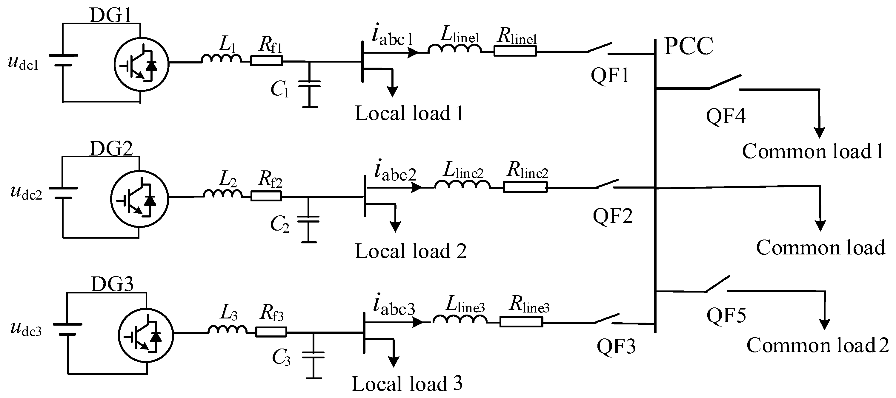
Figure 1. Topological structure diagram of multi-DGs hybrid master–slave control.
Energies 16 00968 g001
Figure 2. Control structure block diagram of virtual synchronous generator.
Energies 16 00968 g002
Figure 3. Control structure block diagram of improved droop control.
Energies 16 00968 g003
Figure 4. Schematic diagram of DG output power.
Energies 16 00968 g004
Figure 5. The block diagram of the improved droop control based on virtual coordinate transformation.
Energies 16 00968 g005
Figure 6. Equivalent schematic diagram of dual-DGs parallel system.
Energies 16 00968 g006
Figure 7. The diagram of the simulation result. (a) Active power output. (b) Reactive power output. (c) The A-phase output voltage of DG1. (d) The A-phase output current of DG1. (e) RMS of PCC. (f) Output frequency of the system.
Energies 16 00968 g007
Figure 8. The experimental platform of a two-machine parallel system.
Energies 16 00968 g008
Figure 9. Waveforms of experimental results. (a) Active power output waveform when capacity setting is 1:1. (b) Reactive power output waveform when capacity setting is 1:1. (c) Active power output waveform when capacity setting is 2:1. (d) Reactive power output waveform when capacity setting is 2:1. (e) Output voltage UPCCa and frequency ∆f with traditional control strategy. (f) Output voltage UPCCa and frequency ∆f with improved control strategy.
Energies 16 00968 g009
Table 1. System parameters.
ParameterValueParameterValue
udc1, udc2, udc3/(V)400Un/(V)220
L1, L2, L3/(mH)4ωn/(rad/s)314.16
J/(kg·m2)
Rf1, Rf2, Rf3/(Ω)
0.15
0.02
K/(Var/V)
C1, C2, C3/(uF)
0.1
10
m1, m2/(kW/Hz)
n1, n2/(kVar/V)
1.38
0.4
Dp/(W/Hz)
Dq/(kVar/V)
8.8
0.8
Rline1 + Xline1/(Ω)0.35 + j0.20Rv1 + Xv1/(Ω)0.35 + j0.3
Rline2 + Xline2/(Ω)0.6 + j0.15Rv2 + Xv2/(Ω)0.1 + j0.35
Rline3 + Xline3/(Ω)0.5 + j0.40Rv3 + Xv3/(Ω)0.2 + j0.1
Table 2. Steady-state value of UPCC and output frequency.
TimeUPCC/Vf/Hz∆UPCC/V∆f/Hz
0 ≤ t < 0.5219.9649.990.04-0.01
0.5 ≤ t < 1217.8249.92−2.14−0.07
1 ≤ t < 1.5215.6249.85−2.20−0.07
1.5 ≤ t < 2217.7349.942.110.09
2 ≤ t < 3216.8549.89−0.08−0.05
3 ≤ t < 4214.649.84−2.25−0.05
Table 3. DG output power distribution results.
Capacity
Settings
TimePei/(∑Pei)/%Qei/(∑Qei)/%Does It Meet the Settings
DG1DG2DG1DG2
1:10 ≤ t < 125.474.627.073.0No
1 ≤ t < 215.384.718.581.5No
2 ≤ t < 349.150.949.550.5Yes
3 ≤ t < 449.550.549.650.4Yes
2:10 ≤ t < 125.075.027.772.3No
1 ≤ t < 217.083.022.777.3No
2 ≤ t < 333.266.833.766.3Yes
3 ≤ t < 432.667.433.966.1Yes
Disclaimer/Publisher’s Note: The statements, opinions and data contained in all publications are solely those of the individual author(s) and contributor(s) and not of MDPI and/or the editor(s). MDPI and/or the editor(s) disclaim responsibility for any injury to people or property resulting from any ideas, methods, instructions or products referred to in the content.