
Influence of the Geometry of the Oxygen Removal Chamber on the Oxygen Concentration in a PEM Water Electrolysis System

Abstract
:1. Introduction
2. Numerical Condition and Methods
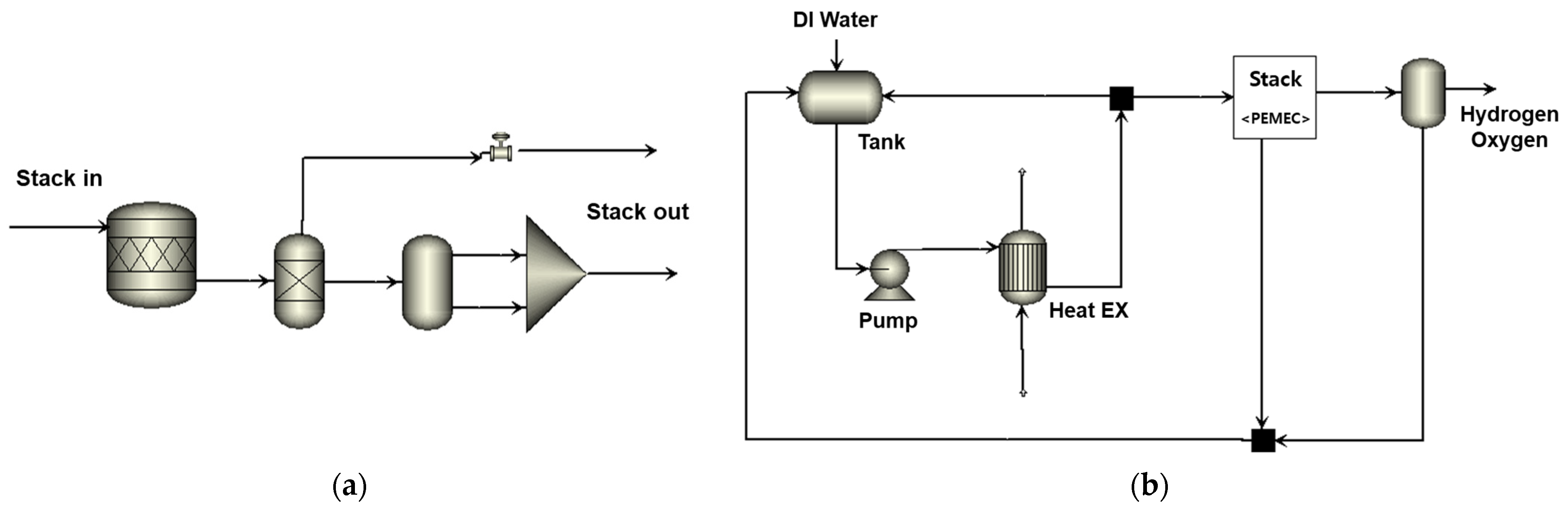
2.1. Process Analysis of the Electrolysis System
2.2. Physical Models and Numerical Methods
2.2.1. Governing Equation
2.2.2. Catalyst Reaction
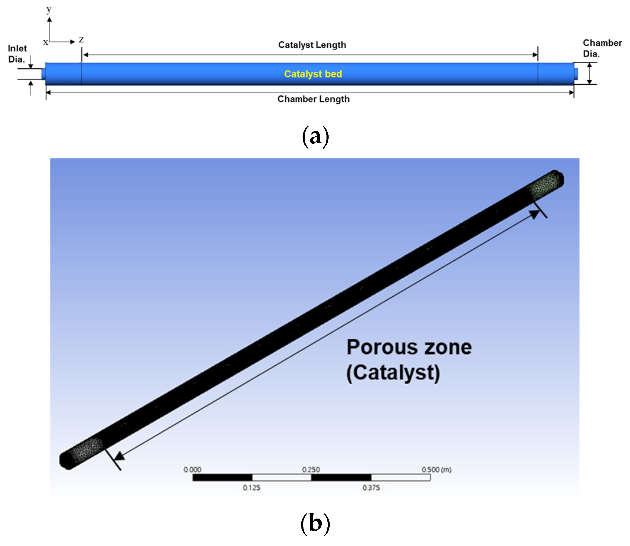
2.2.3. Geometric of the Oxygen Removal Chamber and Boundary Condition
3. Results and Discussion
3.1. Process Analysis of the Water Electrolysis System Using PEM
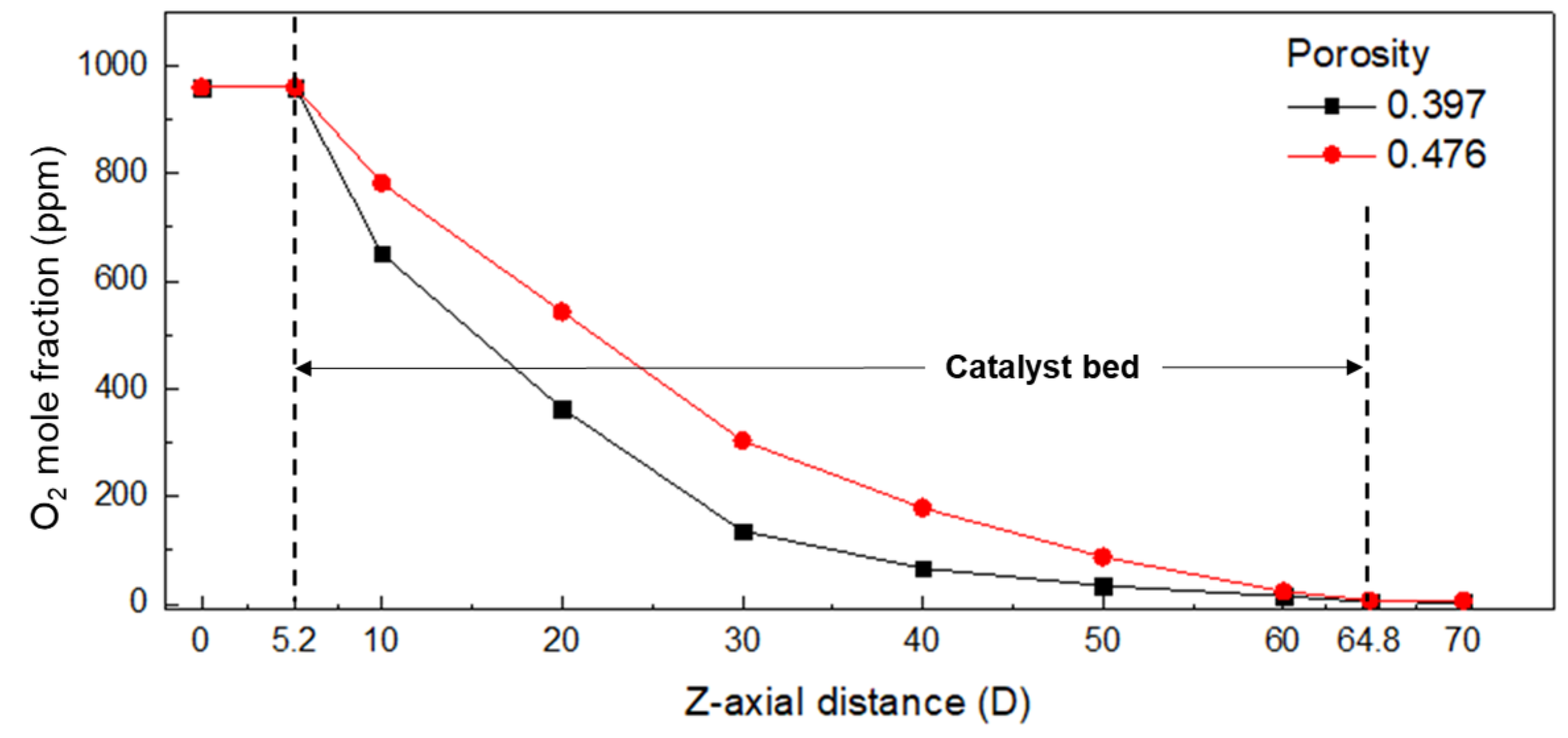
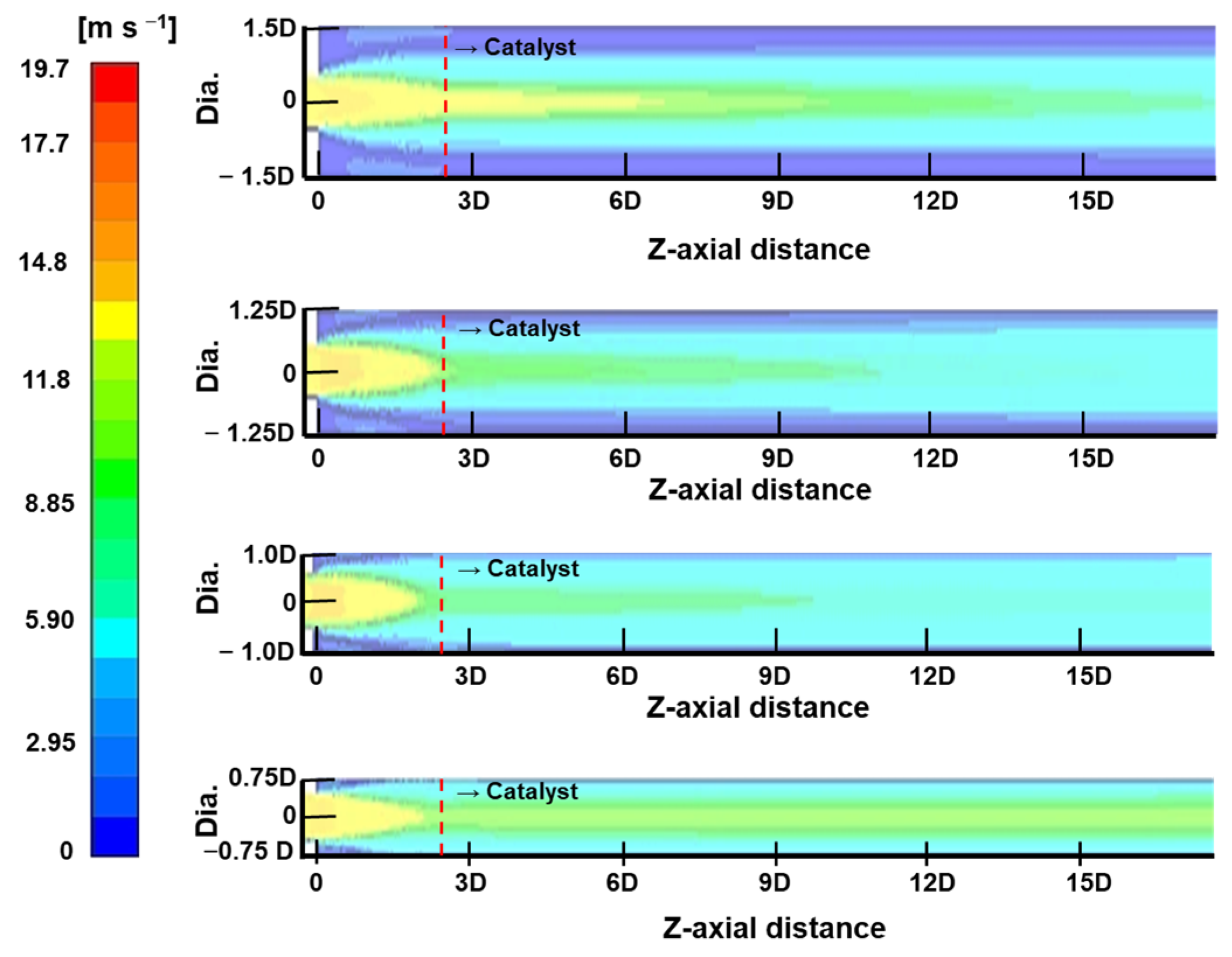
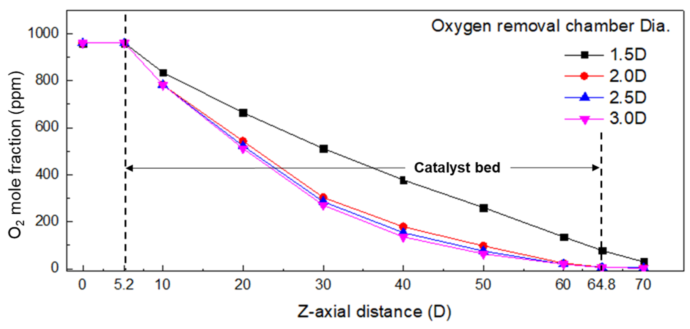
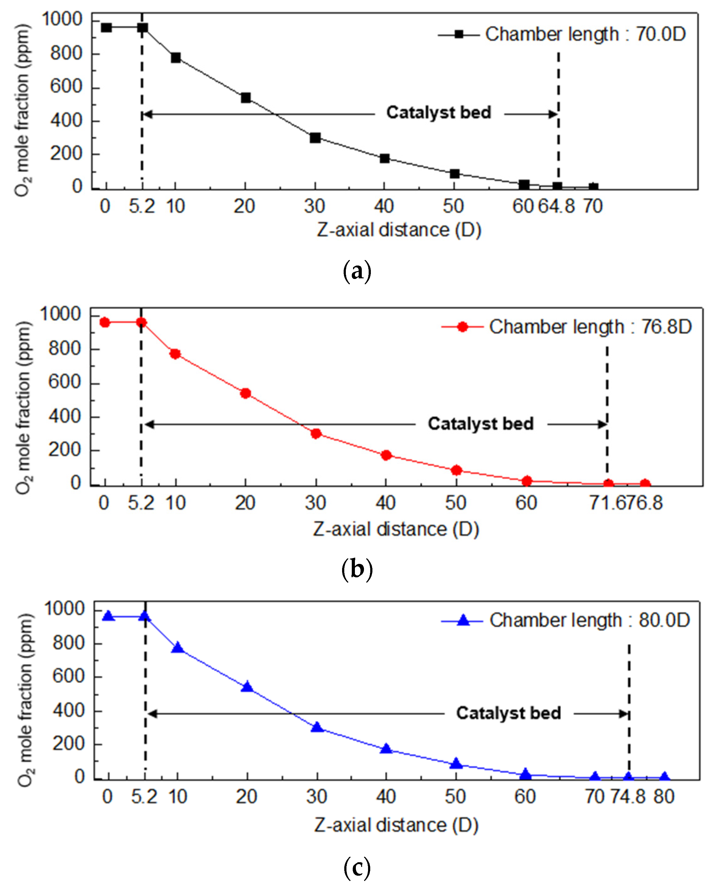
3.2. Effect of Geometry on the Oxygen Mole Fraction
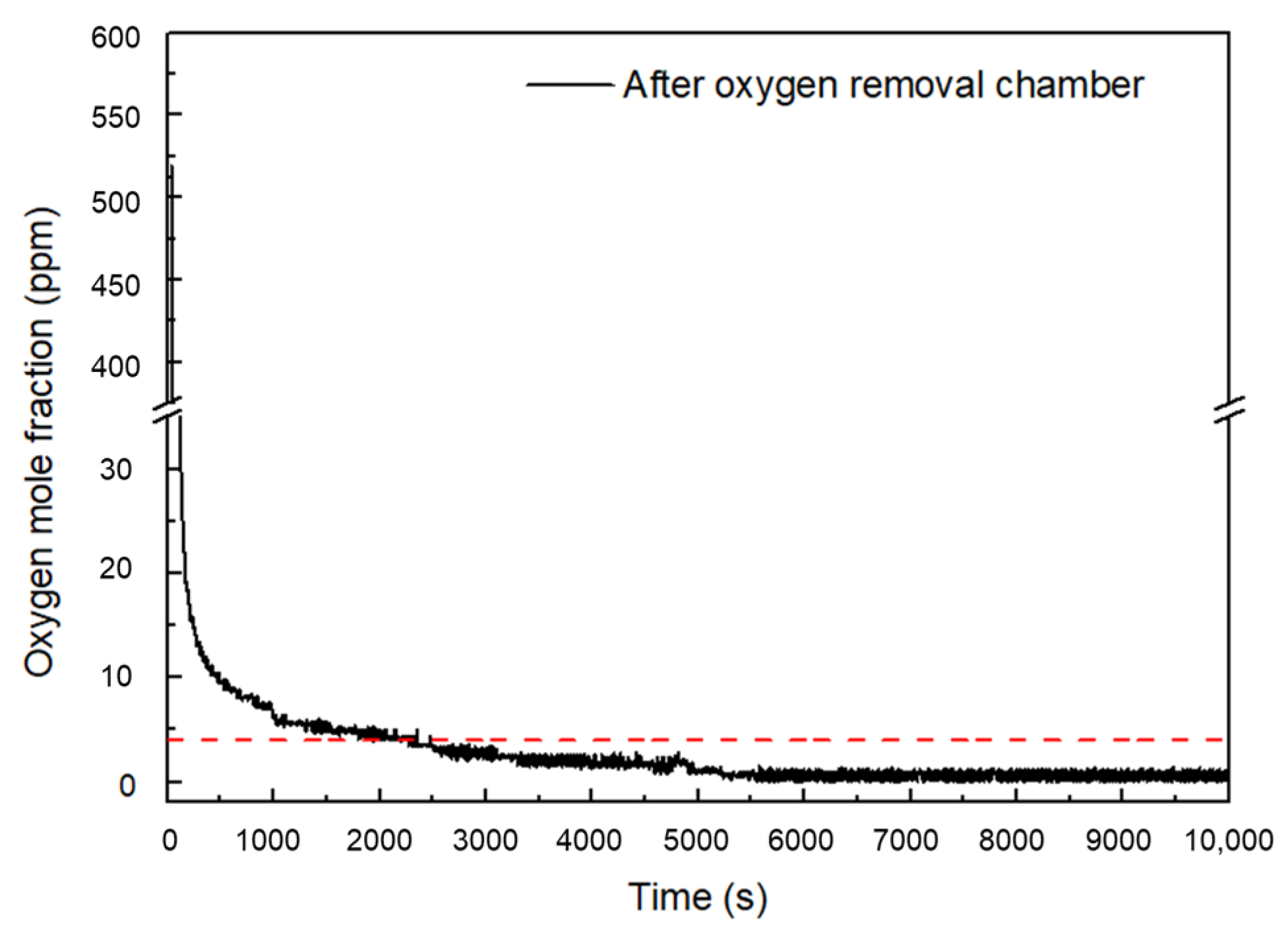
3.3. Verification of the Oxygen Removal Chamber Performance
4. Conclusions
Author Contributions
Funding
Data Availability Statement
Acknowledgments
Conflicts of Interest
References
- Schmidt, O.; Gambhir, A.; Staffell, I.; Hawkes, A.; Nelson, J.; Few, S. Future cost and performance of water electrolysis: An expert elicitation study. Int. J. Hydrogen Energy 2017, 42, 30470–30492. [Google Scholar] [CrossRef]
- Carmo, M.; Fritz, D.L.; Mergel, J.; Stolt, D. A comprehensive review on PEM water electrolysis. Int. J. Hydrogen Energy 2013, 38, 4901–4934. [Google Scholar] [CrossRef]
- Lee, H.; Lee, B.; Byun, M.; Lim, H. Economic and environmental analysis for PEM water electrolysis based on replacement moment and renewable electricity resources. Energy Conver. Manag. 2020, 224, 113477. [Google Scholar] [CrossRef]
- Nikolaidis, P.; Poullikkas, A. A comparative overview of hydrogen production processes. Renew. Sustain. Energy Rev. 2017, 67, 597–611. [Google Scholar] [CrossRef]
- Zhang, L.C.; Chen, H.; Hou, G.R.; Zhang, L.Z.; Li, Q.L.; Wu, Y.K.; Xu, M.; Bao, S.J. Puzzle-inspired carbon dots coupled with cobalt phosphide for constructing a highly-effective overall water splitting interface. Chem. Commun. 2020, 56, 257–260. [Google Scholar] [CrossRef]
- Du, Z.; Liu, C.; Zhai, J.; Guo, X.; Xiong, Y.; Su, W. A review of hydrogen purification technologies for fuel cell vehicles. Catalysts. 2021, 11, 393. [Google Scholar] [CrossRef]
- Clarke, R.E.; Giddey, S.; Badwal, S.P.S. Stand-alone PEM water electrolysis system for fail safe operation with a renewable energy source. Int. J. Hydrogen Energy 2010, 35, 928–935. [Google Scholar] [CrossRef]
- Gahleitner, G. Hydrogen from renewable electricity: An international review of power-to-gas pilot plants for stationary applications. Int. J. Hydrogen Energy 2013, 38, 2039–2061. [Google Scholar] [CrossRef]
- Ogunbode, C.A.; Doran, R.; Böhm, G. Exposure to the IPCC special report on 1.5 °C global warming is linked to perceived threat and increased concern about climate change. Clim. Chang. 2020, 158, 361–375. [Google Scholar] [CrossRef]
- Schröder, V.; Emonts, B.; Janßen, H.; Schulze, H.P. Explosion Limits of Hydrogen/Oxygen Mixtures at Initial Pressures up to 200 bar. Chem. Eng. Technol. 2004, 27, 847–851. [Google Scholar] [CrossRef]
- Schug, C.A. Operational characteristics of high-pressure, high-efficiency water-hydrogen-electrolysis. Int. J. Hydrogen Energy 1998, 23, 1113–1120. [Google Scholar] [CrossRef]
- Yasnev, I.M.; Mel’nichenko, A.N.; Gurskii, V.S. A cellular ceramic as a catalyst support for radiolytic gas recombination devices. Russ. J. Appl. Chem. 2020, 93, 927–932. [Google Scholar] [CrossRef]
- Ge, S.; Xinchun, L.; Weizhong, Q.; Wei, C.; Congyu, S.; Yongjun, S. Recombination of hydrogen and oxygen in fluidized bed reactor with different gas distributors. Energy Proc. 2012, 29, 552–558. [Google Scholar] [CrossRef]
- Ligen, Y.; Vrubel, H.; Girault, H. Energy efficient hydrogen drying and purification for fuel cell vehicles. Int. J. Hydrogen Energy 2020, 45, 10639–10647. [Google Scholar] [CrossRef]
- Haug, P.; Koj, M.; Turek, T. Influence of process conditions on gas purity in alkaline water electrolysis. Int. J. Hydrogen Energy 2017, 42, 9406–9418. [Google Scholar] [CrossRef]
- Lalik, E.; Kosydar, R.; Tokarz-Sobieraj, R.; Witko, M.; Szumełda, T.; Kołodziej, M. Humidity induced deactivation of Al2O3 and SiO2 supported Pd, Pt, Pd-Pt catalysts in H2 + O2 recombination reaction: The catalytic, microcalorimetric and DFT studies. Appl. Catal. A-Gen. 2015, 501, 27–40. [Google Scholar] [CrossRef]
- Kim, G.J.; Shin, J.H.; Chang, H.S. Study on the role of Pt and Pd in Pt-Pd/TiO2 bimetallic catalyst for H2 oxidation at room temperature. Int. J. Hydrogen Energy 2020, 45, 17276–17286. [Google Scholar] [CrossRef]
- Fan, X.; Yuan, W.; Zhang, D.H.; Li, C.M. Heteropolyacid-mediated self-assembly of heteropolyacid-modified pristine graphene supported Pd nanoflowers for superior catalytic performance toward formic acid oxidation. ACS Appl. Energy Mater. 2018, 1, 411–420. [Google Scholar] [CrossRef]
- Yang, Q.; Lin, H.; Wang, X.; Zhang, L.Y.; Jing, M.; Yuan, W.; Li, C.M. Dynamically self-assembled adenine-mediated synthesis of pristine graphene-supported clean Pd nanoparticles with superior electrocatalytic performance toward formic acid oxidation. J. Colloid. Interface Sci. 2022, 613, 515–523. [Google Scholar] [CrossRef]
- Kwon, S.; Eom, S.; Choi, G. Effects of Operating Conditions on the Oxygen Removal Performance of the Deoxo Chamber in the Water Electrolysis System. Energies 2023, 16, 6685. [Google Scholar] [CrossRef]
- Park, T.; Sung, Y.; Kim, T.; Lee, I.; Choi, G.; Kim, D. Effect of static mixer geometry on flow mixing and pressure drop in marine SCR applications. Int. J. Nav. Archit. 2014, 6, 27–38. [Google Scholar] [CrossRef]
- Sung, Y.; Choi, M.; Park, T.; Choi, C.; Park, Y.; Choi, G. Synergistic effect of mixer and mixing chamber on flow mixing and NOx reduction in a marine urea-SCR system. Chem. Eng. Process. Process Intensif. 2020, 150, 107888. [Google Scholar] [CrossRef]
- Chapman, D.L.; Gregory, G. The catalysis by palladium of the union of hydrogen and oxygen. Proc. R. Soc. Lond. A 1934, 147, 68–75. [Google Scholar]
- Adams, B.D.; Chen, A. The role of palladium in a hydrogen economy. Mater. Today 2011, 14, 282–289. [Google Scholar] [CrossRef]
- Völkening, S.; Bedürftig, K.; Jacobi, K.; Wintterlin, J.; Ertl, G. Dual-Path mechanism for catalytic oxidation of hydrogen on platinum surfaces. Phys. Rev. Lett. 1999, 83, 2672–2675. [Google Scholar] [CrossRef]
- Kramer, J.F.; Reihani, S.S.; Jackson, G.S. Low-temperature combustion of hydrogen on supported Pd catalysts. Proc. Combust. Inst. 2002, 29, 989–996. [Google Scholar] [CrossRef]
- Kwon, S.; Eom, S.; Yang, J.; Choi, G. Development of an In-House Code for Dry Tower of Heat Transfer Analysis in Hydrogen Purification System. Energies 2023, 16, 5090. [Google Scholar] [CrossRef]


| Reaction | Ai | Ei |
| Oads + Hads = OHads | 5.7 × 10²¹ | 45 |
| OHads + Hads = H2Oads (H2Ogas) | 5.7 × 10²¹ | 55 |
| Oxygen Removal Chamber | ||
|---|---|---|
| Diameter of inlet and outlet | D | |
| Chamber inner diameter | 1.5 D, 2.0 D, 2.5 D, 3.0 D | |
| Chamber length | 70 D, 76.8 D, 80 D | |
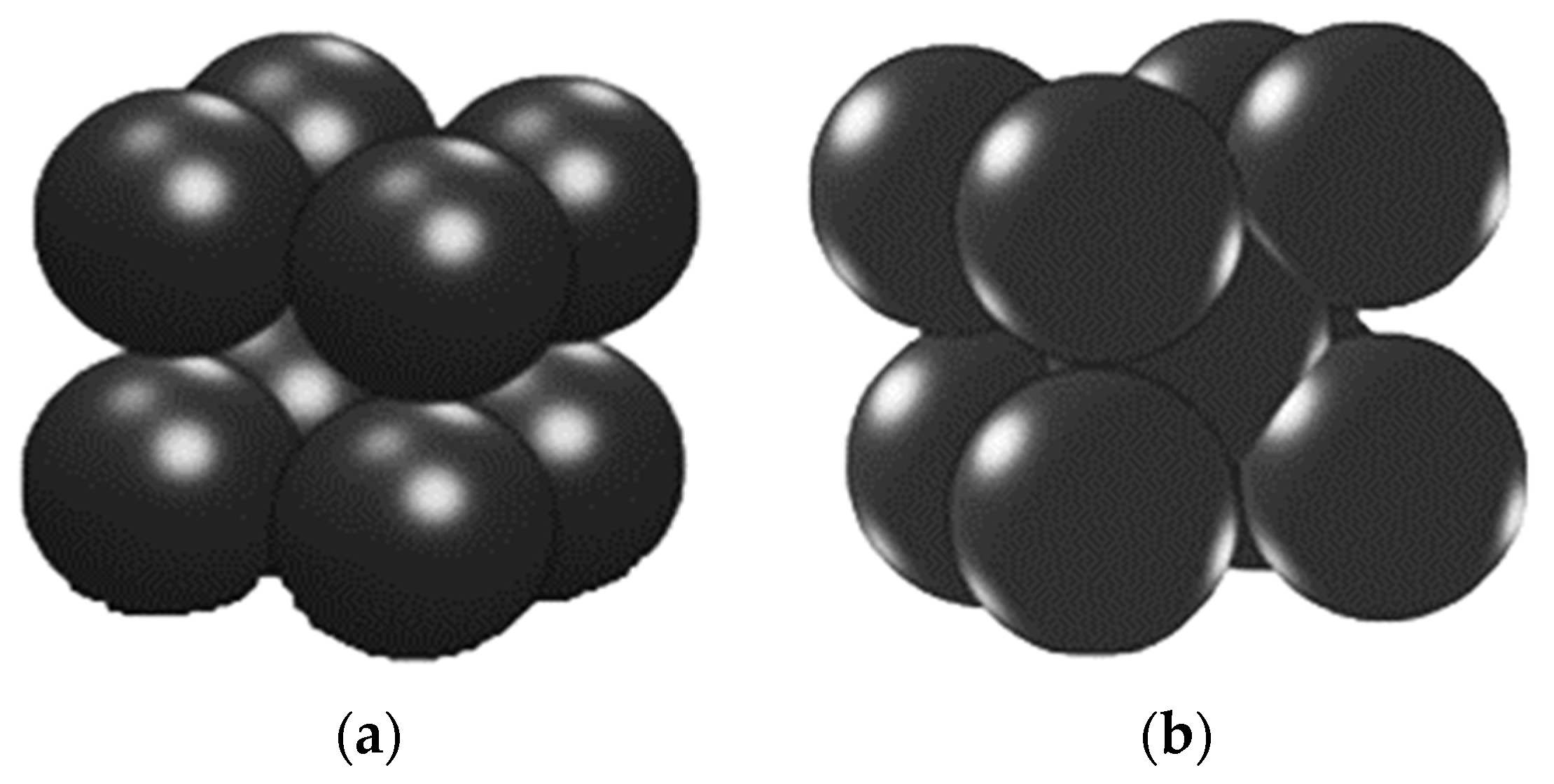
| Catalyst | Mean diameter [mm] | 3 |
| Porosity | 0.397, 0.476 | |
| Length | 25 D, 30 D, 33.2 D, 35 D | |
| Inlet flow [kg/h] | 1.25 | |
| Inlet temperature [°C] | 60 | |
| Pressure [bar] | 6.5 | |
| Stack Inlet | Stack Outlet | Oxygen Removal Chamber Inlet | ||
|---|---|---|---|---|
| Temperature | °C | 50.0 | 60.0 | 60.0 |
| Pressure | bar | 2.0 | 6.5 | 6.5 |
| Mass Flows | kg h−1 | 2337.14 | 35.09 | 1.25 |
| Volume Flow | m3 h−1 | 2.41 | 1.90 | 1.86 |
| Mole Flows | kmol h−1 | 129.73 | 2.38 | 0.505 |
| Mole Fractions | ||||
| H2O | 0.99999 | 0.79376 | 0.02654 | |
| H2 | 0.00000 | 0.20604 | 0.97250 | |
| O2 | 0.00001 | 0.00020 | 0.00096 | |
Disclaimer/Publisher’s Note: The statements, opinions and data contained in all publications are solely those of the individual author(s) and contributor(s) and not of MDPI and/or the editor(s). MDPI and/or the editor(s) disclaim responsibility for any injury to people or property resulting from any ideas, methods, instructions or products referred to in the content. |
© 2023 by the authors. Licensee MDPI, Basel, Switzerland. This article is an open access article distributed under the terms and conditions of the Creative Commons Attribution (CC BY) license (https://creativecommons.org/licenses/by/4.0/).
Share and Cite
Kwon, S.; Eom, S.; Choi, G. Influence of the Geometry of the Oxygen Removal Chamber on the Oxygen Concentration in a PEM Water Electrolysis System. Energies 2023, 16, 7119. https://doi.org/10.3390/en16207119
Kwon S, Eom S, Choi G. Influence of the Geometry of the Oxygen Removal Chamber on the Oxygen Concentration in a PEM Water Electrolysis System. Energies. 2023; 16(20):7119. https://doi.org/10.3390/en16207119
Chicago/Turabian StyleKwon, Sooin, Seongyong Eom, and Gyungmin Choi. 2023. "Influence of the Geometry of the Oxygen Removal Chamber on the Oxygen Concentration in a PEM Water Electrolysis System" Energies 16, no. 20: 7119. https://doi.org/10.3390/en16207119