Review

Recent Development of Heat Sink and Related Design Methods

School of Mechanical Engineering, Shanghai Jiao Tong University, Shanghai 200240, China
*
Author to whom correspondence should be addressed.
Energies 2023, 16(20), 7133; https://doi.org/10.3390/en16207133
Submission received: 4 July 2023 / Revised: 18 August 2023 / Accepted: 13 October 2023 / Published: 18 October 2023
(This article belongs to the Section J: Thermal Management)

Abstract

:
Heat sinks are vital components that dissipate thermal energy from high temperature systems, such as aero-space vehicles, electronic chips, and turbine engines. In the last few decades, considerable research efforts have been devoted to heat sinks to enhance heat dissipation, minimize temperature in the hot spot region, and reduce the temperature of hot section components. At present, the improvement of the thermal performance of heat sinks encounters many bottlenecks and demands the implementation of new designs, new materials, and flexible manufacturing. This study summarized the recent development of heat sinks over five years with a major review of heat transfer aspects, i.e., conduction, convection, radiation, phase change, and nanofluids technology, as well as perspectives in the aspect of structural design. The purpose of this work is to provide an overview of the existing studies that elevate the thermal performance of heat sinks and propose prospectives and suggestions for future studies.

1. Introduction

The development of the industry puts forward increasing demands for heat dissipation that can prolong the life of devices in different fields. Heat dissipation problems are a major obstacle to the advancement of multiple equipment, such as electronic chips, lithium-ion batteries, gas turbines, and spacecrafts, where thermal failure is one of the main forms of failure. Specifically, the temperature of the working substance in gas turbines has continuously increased over the last few decades. For gas turbine blade cooling, we need more efficient heat dissipation technologies. The working properties of lithium-ion battery are sensitive to temperature, which needs an effective heat dissipation system for long cycle life. Most of the heat generated by spacecraft must be dissipated into space through the approach of thermal radiation. Furthermore, improving radiation is the only way that we can manage the temperature without fluid convection. Under such conditions, heat convection is rather difficult, and radiation sometimes becomes essential. Industrial application shows that the heat flux of these equipment has reached 80–1000 W/cm2 [1], while the required operation life ranges from 5000 h to 20 years. Even more critical is the ambience condition of these high-temperature applications, which vary greatly from high vacuum to open atmosphere to narrow channels. Hence, much research has focused on the overall cooling performance of kinds of heat sinks by modifying the structure designs, which can enhance the flow turbulence so that the heat transfer coefficient can also be increased.
Generally, heat sink design is a multi-objective problem in pursuit of high heat transfer, low resistance, light weight, high compactness and high strength. At present, the improvement of the thermal performance of heat sinks encounters many bottlenecks and demands the implementation of new designs, new materials, and flexible manufacturing. Structure is a major concern among the design efforts of heat sinks. Evidenced by numerous studies, the elevation of the cooling performance of heat sinks was achieved by modifying the geometry, having the fluid flow influenced by the complex geometry.
The objective of this paper is to summarize different heat sinks, which are divided by the main heat transfer principles and the structure features, and to provide future research prospectives and suggestions for heat sink optimization by analyzing the remaining challenges. The structure of this review is shown in Figure 1.

Heat Transfer Principles in Heat Sinks

For different kinds of heat sinks, there are three essential heat transfer disciplines to govern the temperature filed inside the structures, which are respectively conduction, convection, and radiation. Heat flows among objects from the region with high temperature to that of low temperature, which is stipulated by the Second Law of Thermodynamics and is related to the temperature difference. These heat transfer disciplines prescribe the means by which heat dissipation studies can be considered.
Within a body containing temperature gradients inside, energy transfers from the high temperature region to the low temperature region, which is thermal conduction. The heat transfer flux is proportional to the temperature gradient to the normal direction; that is, q / A T / x . Then, the proportionality constant is introduced:
q = λ A T x
where q is the heat transfer flux, and T / x is the temperature gradient direction that the heat flows. The constant λ is the thermal conductivity; therefore, it is always positive and the inherent property of materials. Equation (1) is Fourier’s law of heat conduction [2].
For fluid flow, thermal conduction is not the only form of heat transfer due to the direct carriage and transportation of energy by mass, which is called thermal convection. If the convection originates from an external force, that is called forced convection. On the contrary, if the flow is induced by temperature gradient and density difference, it is named natural convection. We used the law of Newton cooling to describe the overall thermal convection effect:
q = h A ( T w T )
Both the temperature difference and the surface area A are related to the heat transfer flux that transfers energy between the static wall and fluid. h is the convection heat transfer coefficient, which is a positive constant [2]. Generally, h needs to be calculated by performing an experiment.
In addition, heat can be transferred through regions within a vacuum environment. The heat transfer approach mentioned is thermal radiation. It is different from the mechanisms that conduction and convection comply, which are material mediums that involve heat energy transfer. The thermodynamic rule indicates that a black body will emit heat energy at a rate proportional to the fourth power of the absolute temperature of the objects and is also related to its surface area:
q e m i t t e d = σ A T 4
where σ is the Stefan–Boltzmann constant and works as the proportionality constant [2].

2. Literature Review of Heat Transfer Studies on Heat Sinks

In this section, the contents are divided based on the main heat transfer principle used by the authors to optimize the capability of heat dissipation.

2.1. Heat Conduction Solutions for Heat Sinks

In the aspect of heat conduction, heat sinks prefer high conductivity to dissipate thermal energy from a heat source distantly. In most cases, the challenges in this aspect are not in the conductivity of the substrate materials but within the solid–solid surfaces. Due to the limitation of machining accuracy, the actual contact area between the heat source and the heat sink might only occur in some discrete local areas, which is much smaller than the macroscopic contact area [3]. The obstacle of heat transfer caused by the roughness between interfaces that affect heat conduction is called contact thermal resistance, which is defined as the additional resistance created by the shrinkage of the heat streamline caused by the contact gaps. Contact thermal resistance is one of the important indicators used to evaluate the heat transfer efficiency between contact interfaces, and it also affects the capacity to dissipate heat adversely. Generally, heat transfers from the heat source region to the base of heat sinks by way of conduction.
Reducing contact thermal resistance is a multidisciplinary cross-scale problem. A method used to achieve it is by filling materials with different thermal conductivities into the contact gaps. With the continuous emergence of research on contact thermal resistance in recent years, many researchers have carried out application results based on the existing studies in many fields, such as mechanical manufacturing, aero-space, and microelectronics. Yang Wang [3] studied the contact thermal resistance of a Press-Pack Insulated Gate Bipolar Transistor (IGBT) to optimize its heat dissipation. The simulation results, using the simplified model and the calculation model that introduced contact interface thermal resistance, were compared to verify that contact thermal resistance was the bottleneck of IGBT heat dissipation, and pressure was the factor that affects contact thermal resistance. Contact thermal resistance was reduced by filling a thin layer of graphene into the contact interface, thereby enhancing the longitudinal heat dissipation of the Press-Pack IGBT.

2.2. Heat Convection Solutions for Heat Sinks

Since most of the current heat sinks realize their heat dissipation function by means of liquid cooling or air cooling, convective heat transfer is a major principle used when designing heat sinks. Based on the specific driving force of convection, heat sinks can be further classified into natural convection heat sinks, forced convection heat sinks, phase transition heat sinks, and heat sinks that use nanofluids.

2.2.1. Natural Convection Heat Sinks

Natural convection heat dissipation is a passive cooling thermal management technique that is frequently used for electronic element cooling. Passive cooling schemes do not need external power sources to drive the various working substances. Instead, the fluid flows though the heat sinks according to the effect of uneven fluid density caused by buoyant force or gravity force. Concerning devices cooled by natural convection heat sinks, recent studies focused closely on the optimization of fins [4]. The main objectives used to improve natural convection heat sinks include overcoming internal flow defects that cannot entrain more airflow into the straight fin channels, enhancing fluid turbulence, and uniformizing the heat sink temperature.
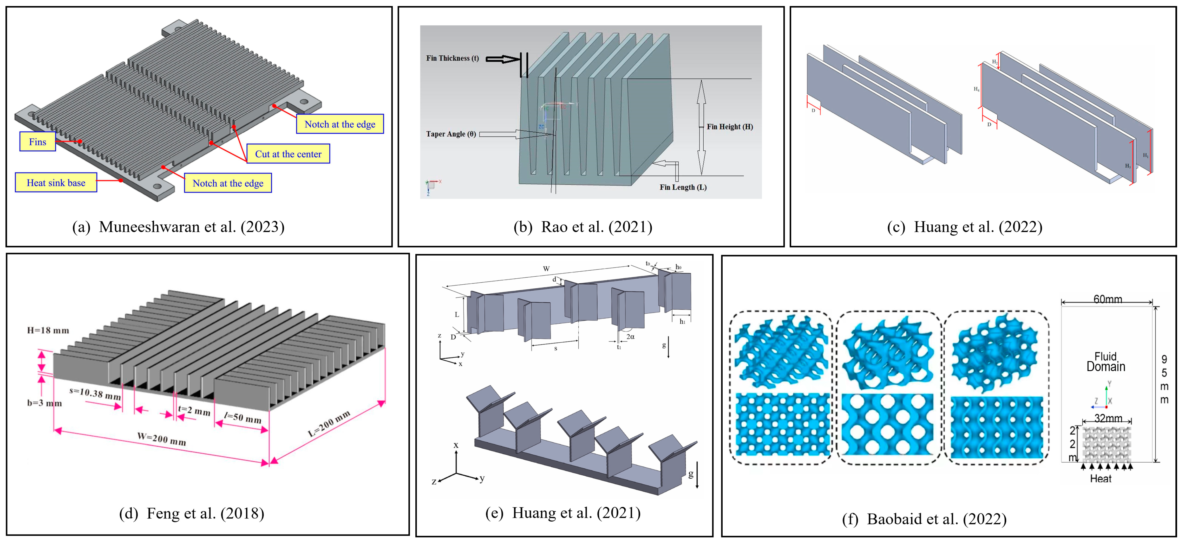
The papers reviewed in this section focus on the shape optimization and configuration optimization of heat sinks. Muneeshwaran et al. [5] found that air entered from the sideward region of the natural convection heat sinks without penetrating deeper inside the channels. In fact, most of the air entered from the sideward region of the straight fins heat sink, flowed bypassing the heat sink, and did not actively participate in heat transfer, which limited its ability to improve heat transfer performance by just improving the fin dimensions and orientations. They proposed a novel inward notched fin design with a portion of fins cut at the center region of the heat sink to induce more airflow into the plate heat sink and concentrated their study on fin height and fin spacing, as shown in Figure 2a. According to their analysis of the numerical simulation results, they obtained a configuration of the heat sink used in the natural convection occasion that had a higher heat transfer coefficient and lower thermal resistance. Rao et al. [6] proposed a tapered fin configuration to improve maximum heat transfer with a decrease in thermal resistance, as shown in Figure 2b. They analyzed tapered angles of 1°, 2°, and 3°. In their experiment, the base of the heat sink was heated with power ranging from 5 to 80 W. The results showed that a larger tapered angle did not make the heat dissipation better because of the air stagnation at the fins origin. The overall heat transfer coefficient of the tapered fin heat sink significantly increased compared to that of the normal straight fins. Huang et al. [7] changed the shift displacement of the fins that were fixed on the heat sink so that the thermal boundary layers among the fins were reconstructed. The novelty and originality of their study were that they combined previous heat dissipation technologies with straight-fin heat sinks used in natural convection situations, in which the shift of the displacement and height of the fins were considered as the design variables simultaneously. According to a comparison of three straight-fin heat sink models, including the novel structure, depicted in Figure 2c, numerical results indicated that the displacement of fins was more decisive in contrast to fin height for minimizing the base surface temperature. Feng et al. [8] designed a cross-fin heat sink including a series of long fins and short fins that were arranged perpendicularly to enhance the heat transfer capability of a natural convection heat sink, as shown in Figure 2d. Numerical simulations considered natural convection and thermal radiation, and they were validated by experiments. The results showed that cold air could reach all of the short-fin channels, which formed an impinging-like flow towards channel end walls, making the cross-fin heat sink better in heat transfer enhancement.
Since the recent revolution in additive manufacturing, researchers have investigated complex geometries that were hard to manufacture by conventional manufacturing methods in the past, such as the branched fin structure and triply periodic minimal surface (TPMS) cellular structure. Huang et al. [9] numerically and experimentally investigated an optimization problem. They designed a natural convection Y-shape-shifted heat sink, as shown in Figure 2e. The objective of their work was to design the fin parameters, such as optimal fin stem height, fin branch length, branching angle, and shift distance of the fins, under some given conditions to minimize the temperature of the base surface and to enhance the cooling performance. The results verified the validity of the optimized geometry of the Y-shape-shifted heat sink. Baobaid et al. [10] investigated three kinds of heat sinks with TPMS bases, which were, respectively, Diamond-Solid, Gyroid-Solid, and Gyroid-Sheet, as shown in Figure 2f. The experiment was performed in a natural convection environment under different enclosure types. According to a comparison of TPMS-based heat sinks with a common pin-fin heat sink under the same experiment conditions, they found that TPMS heat sinks have the proportion of 35–50% improvement in thermal performance for higher effective thermal conductivity. Generally, the air temperature is considered to be a normal atmospheric temperature, and the heat transfer coefficient of natural convection is low. Therefore, the experiment’s setup of the above references had an input heating power of less than 80 W in order to avoid the excessive temperature of electronic devices. The average heat transfer coefficient of these experiment was lower than 15(W/m2·K).

2.2.2. Forced Convection Heat Sinks

Forced convection heat dissipation is a positive cooling thermal management technique used in devices with high heat fluxes, which requires external power sources to drive the working substances. It is realized by forcing the substances to pass through high temperature components and deliver the excessive heat [11]. Due to the faster velocity of flow aroused by the external power source, the active cooling technique obtained higher heat transfer coefficients under the heat dissipation situations. Hence, forced convection heat sinks are frequently used in electronic components. In the papers mentioned in this section, the heating power of the experiment section ranges from 33 W to 1000 W, with the usage of forced convection cooling technology, and the heat transfer flux ranges from 25 to 400 (W/cm2·K).
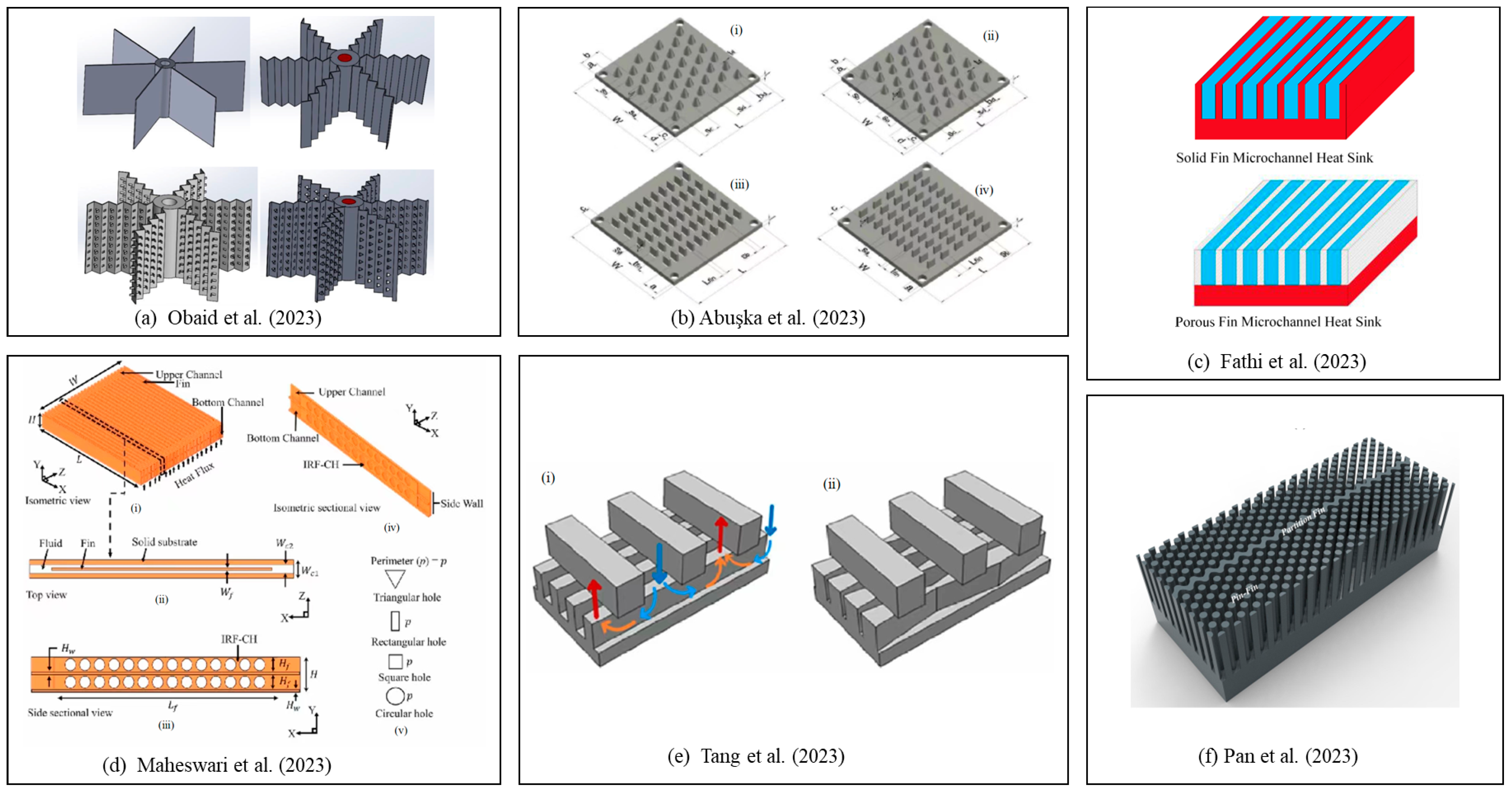
Finned heat sinks are the main subject of this field. Positions, shapes, fitted directions, and lengths of the fin are the variables used to optimize forced convection heat sinks. Obaid et al. [12] proposed four fin configurations under mixed-convection situations. The fin configurations were, respectively, flat fins, corrugated fins, corrugated fins with rectangular perforations with ribs, and corrugated fins with triangle perforations with ribs, as shown in Figure 3a. The numerical simulation showed an enhancement of low voltage sources compared to the traditional flat plate heat sink fins. They concluded that the proposed fin configurations dissipated more heat energy than the traditional ones. Fins with a rectangular perforation and with a ribbed triangular perforation were recommended because they performed better in heat dissipation and had the least amount of weight. Abuşka et al. [13] studied conical pin-fin heat sinks with staggered conical pin fins and modified the staggered conical pin-fin fin placements of their thermo-hydraulic performance, and they compared the heat sinks with cross-cut pin-fin-oriented parallel pin fins and perpendicular cross-cut pin fins to the airflow and a flat heat sink, as shown in Figure 3b. They considered inline and staggered placements, without modifying the staggered placement. The simulation results revealed that the modified staggered conical pin fins had a significantly lower thermal resistance and higher thermohydraulic performance and was preferable to staggered models. The experimental study also indicated that the optimization of the fin height and various aspect ratios could be a potential perspective for the field of heat dissipation in the future.
Microchannel is another category of the research of heat sinks. The working liquid flows through microchannels and then takes away heat from the surface that was heated by high temperature sources; therefore, the microchannel heat sinks improve cooling effectiveness significantly. Microchannel heat sinks have been widely used as efficient heat dissipation devices that have high heat flux thermal management. Fathi et al. [14] noticed that porous fins reduced the pressure drop penalty when used for microchannel heat sinks with straight plate fins. Hence, porous fins have the potential to be an integral part in microelectronic cooling systems. They replaced solid fins with porous fins, as shown in Figure 3c, by comparing different channel heights of microchannels, and they reached the conclusion that porous-fin microchannels outperformed solid-fin microchannels at small channel heights. However, high channel heights resulted in low effective thermal conductivity, and porous fins were not able to dissipate heat effectively. Maheswari et al. [15] studied double-layer microchannel heat sinks and made efforts to enhance the thermal performance of the new designs, which needed a lower coolant flow rate to realize heat dissipation compared with single-layer microchannel heat sinks. The diagram of modified heat sinks is shown in Figure 3d. The numerical results confirmed that modified double-layer microchannel heat sinks had a significant overall thermal performance compared to conventional design. They also analyzed the influence of intermediate rectangular fins placed in the channel and those with different shape holes cut in the fins. It was found that heat sinks with circular and triangular holes consistently had superior heat transfer performance compared to the other two types of holes among all the considered cases.
Manifold microchannel heat sinks (MMCHS) are the representative evolution of normal microchannel heat sinks. The manifold is positioned perpendicular to the microchannel and serves as a diverter for cooling air and forms a number of inlets and exits, which not only increases the heat transfer surface area but also significantly reduces temperature variation. The studies on the performance of MMCHS can be divided into two main categories, the dimensions of important parameters and the layout of the manifold. Tang et al. [16] combined two enhancement methods of diverging/converging channels and proposed a novel type of MMCHS with these two geometric characteristics. They explored key parameters using numerical simulations, which were the inlet/outlet ratios of the manifold and channel, as shown in Figure 3e. The results showed that a moderately diverging manifold layout and a converging channel layout, respectively, have the best enhancement effect on heat transfer for the given pumping power because they better reduced thermal resistance compared to the homogeneous structure. The novel configuration was also superior to the original one in terms of temperature uniformity. Pan et al. [17] proposed a pin-fin staggered manifold microchannel heat sink, in which pin fins were staggered on the plate, and two adjacent rows of pin fins connected to form a wall fin, which was considered the partition fin. In order to further enhance thermal performance, they designed a staggered divider plate, as shown in Figure 3f. The results showed that the pin-fin staggered manifold microchannel heat sink performed better than pin-fin manifold microchannel heat sinks and rectangular manifold microchannel heat sinks regarding heat transfer capability, and they resulted in a more uniform surface temperature.

2.3. Radiation Solutions for Heat Sinks

Due to the vacuum environment in outer space, convection becomes nearly impossible for heat dissipation. Under such situations, the heat generated by the components of spacecraft is conducted by the parts in contact with each other, and then, most of it is transferred into space through thermal radiation [18]. The heat transfer area and the emitted electromagnetism of heat sinks are the major metrics of radiative heat sinks. At present, mass and volume of the heat sinks used in spacecrafts are large, having an adverse influence on the overall layout of spacecrafts and the total launch weight.
Existing studies indicate that establishing a concavo-convex microstructure on the heat transfer surface can enhance the radiation efficiency to increase the surface area. Zhao et al. [18] proposed three types of microstructures to increase the radiant heat flow rate per unit mass of the fins on the base of the idea mentioned, and the structures are shown in Figure 4a. The experiment simulated the space environment, the ambient temperature was 3 K, the initial temperature of the fins was 293.17 K, and the emissivity setup was for 0.85. The effects of the configuration parameters were analyzed to evaluate the improvement of heat dissipation performance, such as microstructure height, top angle, heat source spacing, and environment temperature. It was found that, with a microstructure thickness to fin substrate thickness ratio in a certain range, the radiation heat dissipation of the optimized fin was greater than that of the flat plate. Kuji et al. [19] studied a high-efficiency radiator that used thermal radiation as the main principle of heat dissipation at the target operating temperature. They fabricated a hybrid design with periodic V-grooves on an aluminum surface and a type of submicron periodic microstructure, as shown in Figure 4b. The results revealed that the hybrid structure exhibited higher emissivity across the entire measured wavelength range. Wang et al. [20] studied a heat sink with fins working in a thermoelectric conversion system, shown in Figure 4c. The heat dissipation, involving the radiation heat transfer on the fin surface and the electrical performance of the thermoelectric system, was investigated and tested in the experiment. According to the experiment and numerical simulation, changing fin parameters could influence the extent of the radiation heat exchange between fins and the external environment. The results showed that the radiation heat transfer was mainly determined by the angle factors of different fin surfaces. Furthermore, the larger heat transfer area had the better heat dissipation effect.
This part displays heat sinks used in outer space, in which thermal radiation works as the main approach to achieve heat dissipation. Due to the consideration of cost and the vacuum environment, the challenge of thermal radiation heat sinks is to lighten the weight of cooling systems on the basis of designing or adding novel structures.

2.4. Phase Change Heat Sinks

A new type of passive thermal management technology that uses phase change materials (PCM) has aroused widespread attention from many researchers in recent years. The goals of studying phase change material are to solve the thermal runaway propagation suppression of thermal management systems and to further improve the heat dissipation performance.
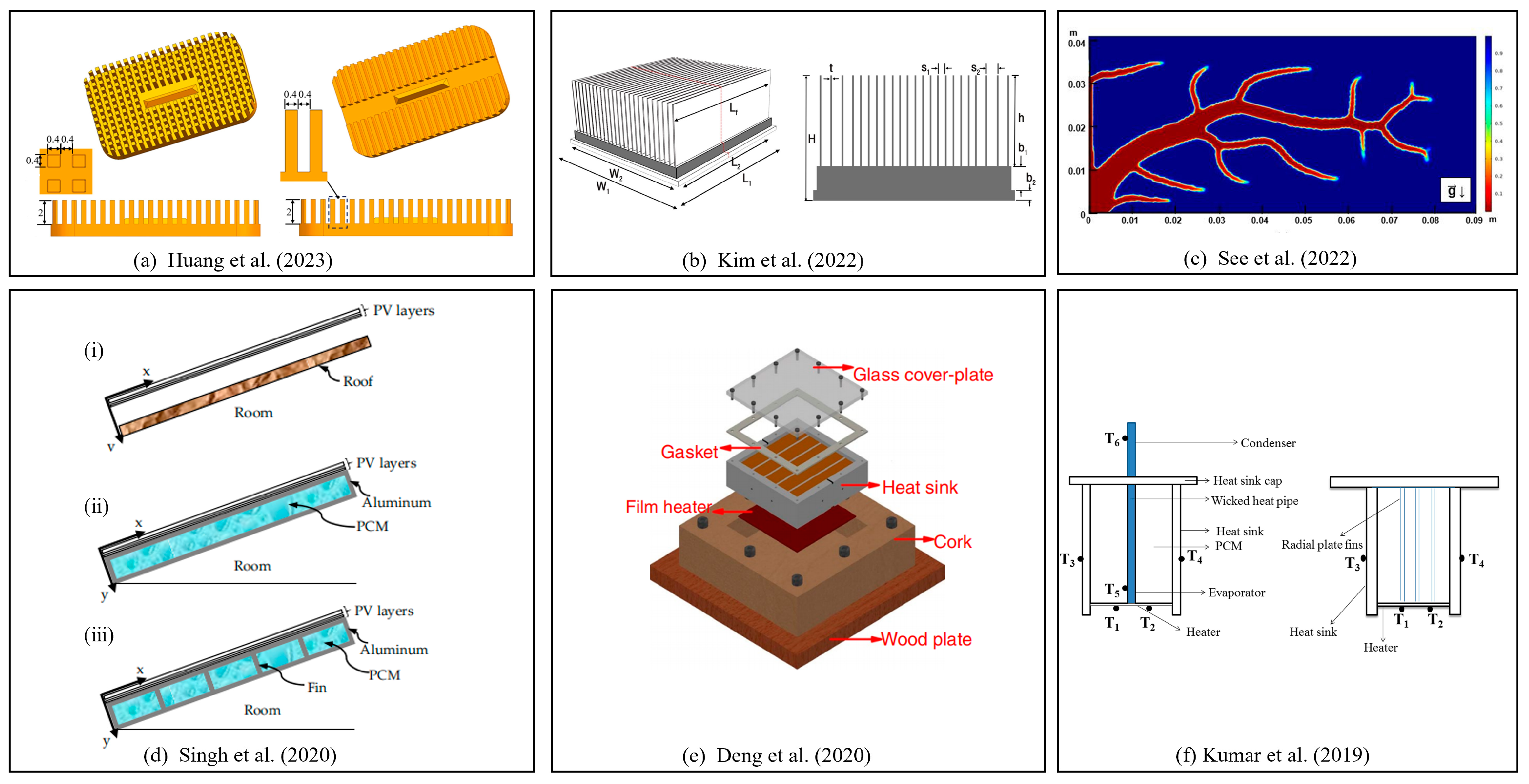
Huang et al. [21] proposed a radial micro pin-fin heat sink combining both the merits of the micro pin-fin structure and the central inlet jet configuration, as depicted in Figure 5a. Flow boiling experiments with ammonia were investigated in a wide range of conditions, including the influence of the heat and mass fluxes, saturation temperature, inlet condition, and pressure drop values. Ammonia, due to its favorable thermodynamic properties, was selected as the working substance, and flow boiling experiments with ammonia were conducted in various conditions. The results verified the promising cooling performance of the radial micro pin-fin heat sink among the devices with high temperature hot spots. Kim et al. [22] proposed a novel heat sink by combining modified designs and using integrated fins filled by phase change material. The proposed scheme was fabricated by embedding the phase change materials to the base plate of the heat sink, as depicted in Figure 5b. In order to minimize the increase of the thermal resistance of the base plate by embedding PCM, the circular hole arrays were fabricated in an aluminum base plate, and phase change composites with paraffin in copper foams were installed within the circular holes. The results indicated the promising application of the embedded PCM for high thermal conductivity. See et al. [23] utilized a PCM interspersed through a finned structure to improve the cooling capacity of the heat sinks with a topology optimization method. The generation of the topology-optimized structure is shown in Figure 5c. The optimized PCM-based heat sink enhanced the heat conduction of the fin structures and improved convection. The results showed that the natural convection topology-optimized heat sink could maintain a low temperature of the base surface. Singh et al. [24] conducted an investigation of finned PCM heat sinks, aiming at the improvement of photovoltaic (PV) cooling capacity. They proposed three polycrystalline silicon-based roof-integrated PV systems, consisting of reference PV panels, the PCM container integrated at the back of the panel, and the PV integrated with PCM and fins. The structures are depicted in Figure 5d. The results showed that the PCM heat sink could reduce the peak temperature. Deng et al. [25] investigated the configuration optimization for phase change material-based heat sinks, and the configurations of the fins are shown in Figure 5e. They analyzed the dynamic temperature response and the melting front evolution in heat sinks and found that the addition of fins enhanced the heat dissipation capability of PCM-based heat sinks. Compared to the heat sink with a cavity, the melting rate was faster and the temperature distribution was more uniform. Kumar et al. [26] conducted an investigation considering a PCM heat sink with embedded radial plate fins and studied the effect of different fill ratios of PCM in the pipe. The settlement of equipment is shown in Figure 5f. The heat sink without PCM was considered the base line, while the charging and discharging cycles were quantified by enhancement and reduction ratios, respectively, in terms of time to reach a certain temperature. It was proven that the heat pipe enhanced the charging and discharging performances of PCM at all fill ratios and all power values by comparing it with a heat sink with embedded radial fins. This investigation shows the potential to use the latent heat of PCM in heat sinks with symbiotically joined heat pipes.
Generally, different phase change materials have different phase transition temperatures and latent heat capacities and are suitable for different applications, resulting in significant differences in the experimental or simulated heating temperature, rated power, heat fluxes, and other parameters. In this section, PCM heat sinks show better thermal performance in the field of electronic chips because phase change materials have the capacity to use sensible heat as well as latent heat energy, which make them ideal cooling schemes for a local hot pot with a high heat flux. Meanwhile, the need for a good sealing environment for PCM heat sinks shows remaining challenges that researchers need to perform further studies so that PCM heat sinks can be used in more complex situations.

2.5. Nanofluid Heat Sinks

Previous studies have found that convective heat transfer using mixed nanofluids can significantly improve heat transfer performance. Nanofluid is a suspension formed by adding solid particles of nanometer size to a convective heat transfer working fluid. Due to the collision between nanoparticles and the surrounding environment, the development of the boundary layer is disrupted, and the interaction between mixed fluid nanoparticles improves the heat transfer coefficient of the cooling fluid, resulting in the enhancement of the thermal performance of the fluid. Therefore, it has become a promising design scheme for heat sinks. However, the further study of nanofluid needs to consider all different parameters, since the cooling effects of nanofluid are the comprehensive effect of gravity, buoyancy, the Brownian motion of nanoparticles, the friction factor, viscous dissipation effects, and Lorentz force in the magnetic field, with fluid divided into Newtonian nanofluid and non-Newtonian nanofluid [27,28].
Designing nanofluid heat sinks is an effective way to enhance heat transfer performance by improving fluid characteristics. At present, research on nanofluids includes adding different nanoparticle materials (including chemically stable metals, metal oxides, and various forms of carbon) to the base fluid, nanoparticle size, the volume fraction of nanoparticles, and nanofluid inlet velocity. According to past research, combining nanofluids as cooling media with microchannels can obtain better heat dissipation capabilities than single-phase cooling fluid.
Wang et al. [29] focused on the heat transfer characteristics with different concentrations (0.001 vol%, 0.01 vol%, and 0.1 vol%) of Al2O3–H2O nanofluids, which were used as cooling fluids in parallel flat minichannels. They studied the irreversible process result of the pressure drop and temperature difference, while entropy generation was applied to analyze the thermal performance of nanofluid heat dissipation systems. In the experiment section, the Al2O3–H2O nanofluids flowed through 11 rectangular cross-section parallel flat tube minichannels steadily. According to the experiment, the transition point from laminar to turbulent flow was confirmed; heat transfer improved with the increment of nanofluid concentration, which indicated low-concentration Al2O3–H2O nanofluids; and it showed better heat dissipation performance under low flow resistance. Azodinia et al. [27] studied Al2O3–H2O nanofluids with the volume fraction of nanoparticles varying from 0% to 3% flowing in a microchannel with a bump, and they assessed particle concentration, slip flow, and the Reynolds number. In the test section, a circle bump was designed in the center of the microchannel with a half millimeter. According to computational results, the heat transfer effect of Al2O3–H2O nanofluids was better than that of the pure base fluid. Al-Rashed et al. [28] investigated CuO nanoparticles, which are non-Newtonian nanofluids, in an offset strip-fin microchannel heat sink, the structure of which is shown in Figure 6. The objectives of their study were to optimize the strip fin geometry and to study the influence of Reynolds number variation and the concentration of CuO nanoparticles. The simulation results indicated that a high concentration of nanoparticles enhanced the heat transfer capability of the nanofluid, the strip fins increased the disturbance, and the high Reynolds number also improved the heat transfer efficiency. Mansouri et al. [30] explored hybrid nanofluids by comparing the thermal performance of graphene oxide (GO)–gold/water and GO/water nanofluid that is used in cooling computers’ CPU. According to the experiment and curve fitting method, the hybrid nanofluids, GO–gold/water, have a greater potential to be applied in cooling systems. Kumar et al. [31] investigated the particle ratio of hybrid nanofluids in a minichannel heat sink, with the mixing ratios being, respectively 5:0, 4:1, 3:2, 2:3, 1:4, and 0:5. The experiment tested different inlet temperatures by focusing on Nusselt number, pressure drop, and friction factor. The results revealed that the hybrid nanofluid mixture ratio had a significant effect on heat transfer and pressure drop, and the mixture ratio around 3:2 was best.

3. Literature Review of Structure Designs and Optimization Approaches

This section groups publications based on the types of structures in heat sinks. The utilization of different kinds of structures usually aims to achieve the better function of heat dissipation, to sustain variable application situations, to meet economic requirements, or to reduce device weights. There are multiple ways to optimize the structure of heat sinks, such as adding surface features, modifying the fin shapes, changing the internal structure of microchannels, filling lattice structures in heat sinks, etc.

3.1. Surface Features

Interrupting the fluid inside heat sinks with surface features is an effective way to improve the thermal performance. This category of heat sink structures usually has a major disturbance on the boundary layers in side cooling channels, while its influence on the main stream channel flow is minor. Previous studies on surface features mainly concern the characteristics of the friction factor and heat transfer.
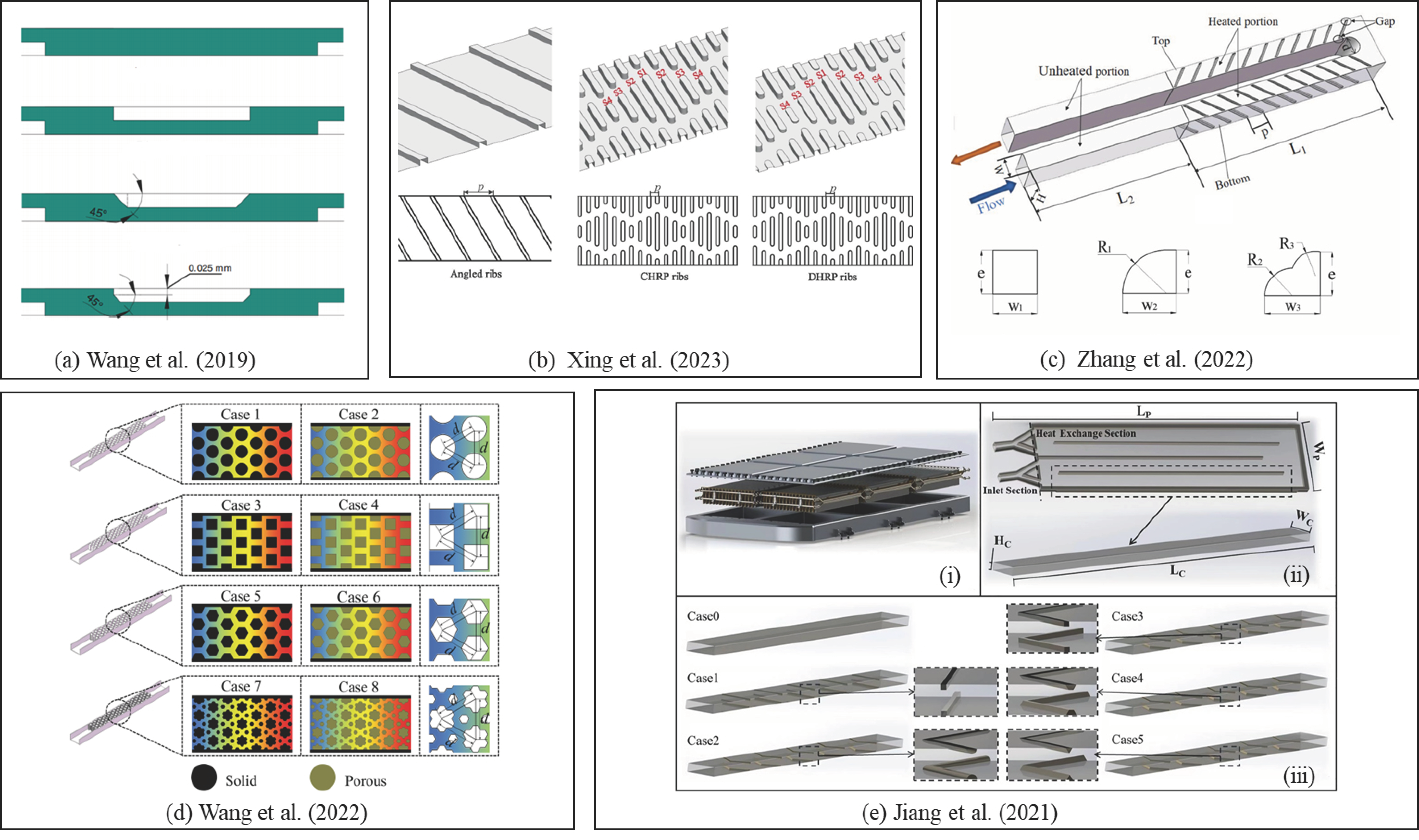
Wang et al. [32] numerically investigated the fully developed laminar flow in a microchannel heat sink with interrupted ribs. They compared four kinds of IMCHS with no ribs, rectangle ribs, triangle ribs, and trapezoid ribs to analyze the factors that may be helpful to enhance heat dissipation, as shown in Figure 6a. In addition, the effect of rib chamfer was also discussed. The results revealed that IMCHS with ribs significantly increased local heat transfer and friction performance on the windward side of the ribs, which proved that IMCHS with ribs could enhance the heat dissipation. Xing et al. [33] designed discrete rib structures on the basis of bionic sharkskin scales with a rhombus-shaped pattern inside the channel for gas turbine, as shown in Figure 6b. For steam and air-cooling systems, decreasing the height of the bionic ribbed channel consistently displayed the best performance. This is because decreasing the height reduced the flow resistance compared to rhombus-shaped ribs with a constant height. The results showed that it was better to design more complex structures and smaller-sized ribs for cooling systems. Zhang et al. [34] proposed a novel rib that had a petal-cross section in order to study a two-pass internal cooling channel for a gas turbine blade, as shown in Figure 6c. Compared to the normal square shape and a-quarter-cylinder shape rib under the identical cross-sectional area and rib height, the numerical simulation results demonstrated that ribs with curved surfaces, including a-quarter-cylinder ribs and petal-shaped ribs, effectively increased the mixture of fluid with temperature difference, therefore enhancing the heat dissipation in the microchannel. Wang et al. [35] proposed four shapes of ribs inspired by the fantastic features of honeycomb in nature to overcome the drawbacks, which are found in complex rib structures in microchannels, of making the friction factor increase and needing higher pumping power. The regular-shaped rib, hierarchical honeycomb-shaped rib, circular-shaped rib, square cross-section-shaped rib, and ribs of all shapes were, respectively, filled with solid media and porous media, as shown in Figure 6d. The results indicated that the comprehensive performance can be significantly promoted at different levels using porous ribs. In order to lower the pump power consumption for the battery cooling systems, Jiang et al. [36] considered the rectangular channel of the liquid cold plate, aiming to study the flow and heat transfer characteristics of adding V-shaped ribs with different cross-sections. The structure is shown in Figure 6e. The results revealed that the heat transfer efficiency of the V-shaped ribbed channel was higher than that of the smooth channel when using pump power consumption as the baseline, and it had a smaller heat flux.
The heat sinks are grouped on the basis of novel surface feature design. It is indicated that adding a microstructure on the surface of heat sinks, which have fluid flow on them, can complicate flow features with lower pressure loss. Moreover, surface feature structures increase the heat transfer area to a certain extent. Therefore, this kind of optimization for heat sinks can work in both natural and forced convection thermal management.

3.2. Fins

Fins are another commonly used structure type in heat sinks. Compared to surface features, fins are usually large internal features in cooling channels, which cause significant 3D vortices and mixing inside heat sinks. These structures are usually presented as extruded geometries.
Rinawa et al. [37] explored three varieties of fins, namely fins with a rectangular cross section, multiple steps, and multiple steps with dimples, as shown in Figure 7a. According to the investigation, fins with round dimples had a higher efficiency than the three other structures because the temperature difference and heat transfer coefficient were greater. In addition, the results showed that the wake region was condensed, and the drag was elevated in fins with dimples, which increased the time of interaction among the high-temperature fins and the ambient air so that the overall performance improved. Micro pin-fin heat sinks and microchannel pin-fin heat sinks are effective cooling management methods. Chiu et al. [38] proposed a heat sink with a variable density pin-fin configuration to investigate the flow characteristics, as well as heat transfer, which aimed to solve the temperature non-uniformity of chips in electronic devices. They studied three types of arrangements, respectively, staggered, convergent, and convergent-divergent types, as shown in Figure 7b. According to the numerical simulation, because the flow mixing in the heat sink with a convergent-divergent fin arrangement was more than enough with the staggered arrangement, the proposed structure had a lower effective thermal resistance than the other form. It also revealed that the parameter of pin density arrangement was an important factor for improving the temperature uniformity of heated surface. Saravanan et al. [39] investigated the combined effect of a pin fin and microchannel heat sink. They proposed a microchannel heat sink with square pin fins and one with circular pin fins. The structure is shown in Figure 7c. The results showed that, compared to pin fin heat sinks in terms of heat transfer enhancement, the hybrid structure heat sink could be a significantly better alternative for electronic devices.
The usage of fins is an effective technique in natural convection heat dissipation engineering applications. Rath et al. [40] conducted numerical simulations to explore the implications and performance of wavy longitudinal fins over straight longitudinal fins for heat dissipation augmentation in natural convection; the structure is shown in Figure 7d. It was noted that wavy fins intensified the thermo-buoyant flow and augmented the heat dissipation from the fin surface at certain ranges of the pertinent parameters. The results showed that, at a higher number, wavy fins outperformed straight fins. Karlapalem et al. [41] studied the effect of a multiple-branch structure under laminar natural convection in three different orientations. The novelty and originality of this study were that it considered the effects of asymmetry and different orientations. The directions of gravity and its action along the length of the fins are shown in Figure 7e. According to the investigation, fins with two, three, or more branches in three different orientations were determined to have the best configuration to maximize heat dissipation in the cases of vertical-base horizontal fins, vertical-base vertical fins, and horizontal-base vertical fins. The investigation of fin designs formed the basis for testing other natural convection applications, in which conventional straight fins or other kinds of branching fins are used.
Similar to surface features, fins enhance the disturbance so that the heat sinks with pin fins or plate fins also show higher convection heat transfer coefficients. At present, there are many designs for finned heat sinks, including new fin structures and different configurations. However, further exploration is needed to develop quantitative design conclusions for pin fins and straight fins, respectively.

3.3. Microchannels

Microchannel heat sinks are a commonly used type of heat dissipation device, in which the coolant flows through channels with a very short height. This type of heat sink usually deals with heat dissipation problems within a very limited space, and the hydraulic diameter ranges from 1 to 1000 microns [42].
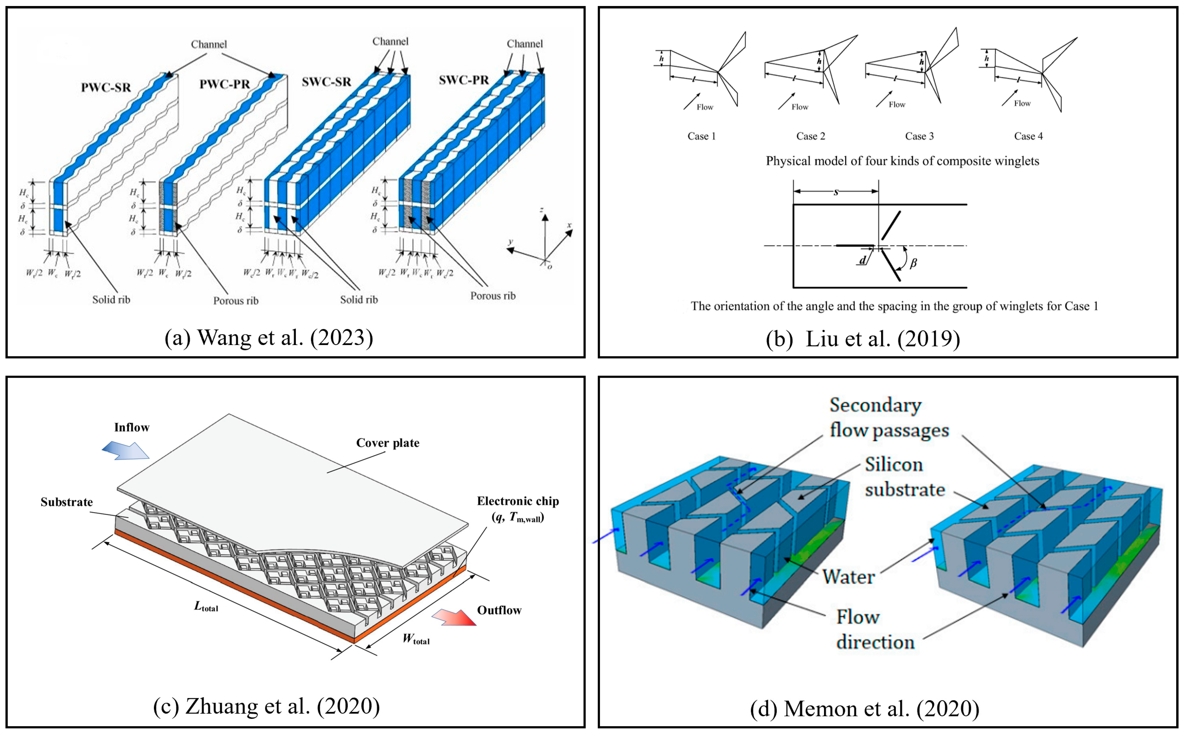
Wang et al. [43] compared and optimized two wavy configurations in double-layered microchannel heat sinks with parallel and symmetric wavy porous fins. The novelty of this research is that their work was based on a synergistic design concept. For a wavy two-layered microchannel heat sink, they proposed the porous-fin design to replace the solid fins to improve the cooling performance. Four designs, including a symmetric configuration with solid ribs, a symmetric configuration with porous ribs, a parallel configuration with solid ribs, and a parallel configuration with porous ribs, were investigated, as shown in Figure 8a. The results represented overall superiority of pressure drop reduction, heat transfer enhancement, and cooling uniformity improvement. Liu et al. [44] numerically investigated a channel with delta winglet vortex generators arranged to cause large-scale vortices because winglet vortex generators can introduce vortices by increasing fluid friction and separation so that the heat transfer is enhanced. They arranged four different combinations of delta winglet cases and studied the parameters of the layout to explore their heat dissipation and flow performance. The structure of four cases and the configuration of winglets are shown in Figure 8b.
Zhuang et al. [45] proposed a microchannel heat sink that designed the distribution of multiple rhombus fractal-like units in the microchannel, with the objective to lower the pump power, and the design scheme was validated by experiments. The new architecture was inspired by the bionic structure of a branching vessel tree structure, which has a high-efficiency for mass transport in human bodies, as shown in Figure 8c. The advantage of this heat sink lies in its potential capability to improve the cooling efficiency by reducing the pump power. More branching channels led to the increase of the total channel cross-section area so that it could diminish the frictional pressure drop, thereby reducing pump power. The results indicated that the fractal-like units may effectively improve the cooling efficiency. Memon et al. [46] studied the effect of secondary flow in two different microchannel heat sink designs, as shown in Figure 8d. The results showed that the I-type inlet-outlet configuration performed better than that of the C-type and Z-type. The heat sinks with secondary flow enhanced heat absorption and temperature uniformity on the base plate, especially at higher flow rates. The studies provided a performance benchmark for similar studies involving secondary flow. Gilmore et al. [47] generated novel MMCHS structures for devices that may have high heat fluxes by applying topology optimization within a multi-objective three-dimensional conjugate heat transfer model. They considered three optimization cases by using flow and heat transfer models, in which they, respectively, only considered the liquid portion of the microchannel without heat transfer and that with heat transfer. Their study optimized the topology of MMCHS, aiming to exhibit the possibility of significant performance enhancement with this design direction and process.
Microchannel heat sinks are the most widely used, especially in compact electronic devices. Table 1 summarizes all the microchannel heat sinks in this review, with the information of author, study methods, and main structure features. There are various microchannel heat sinks used in different situations. Among them, hydraulic diameter, channel cross-section shape, and channel wall structure features are the main design parameters that need further studies, and the usage of additive manufacturing is a remaining challenge. The mass production of complex structures is impossible for the current microfabrication techniques, but it may generalize with the development of manufacturing techniques, especially additive manufacturing.

3.4. Latticework

Latticework is a type of periodic 3D cellular structure that can be used for heat transfer enhancement as well as structural support. Among various latticework structures, emerging kind of cellular materials are the triply periodic minimal surfaces (TPMS). TPMS are mathematically defined and have various surfaces with complex topology methods that are divided into several interlocked and connected domains.
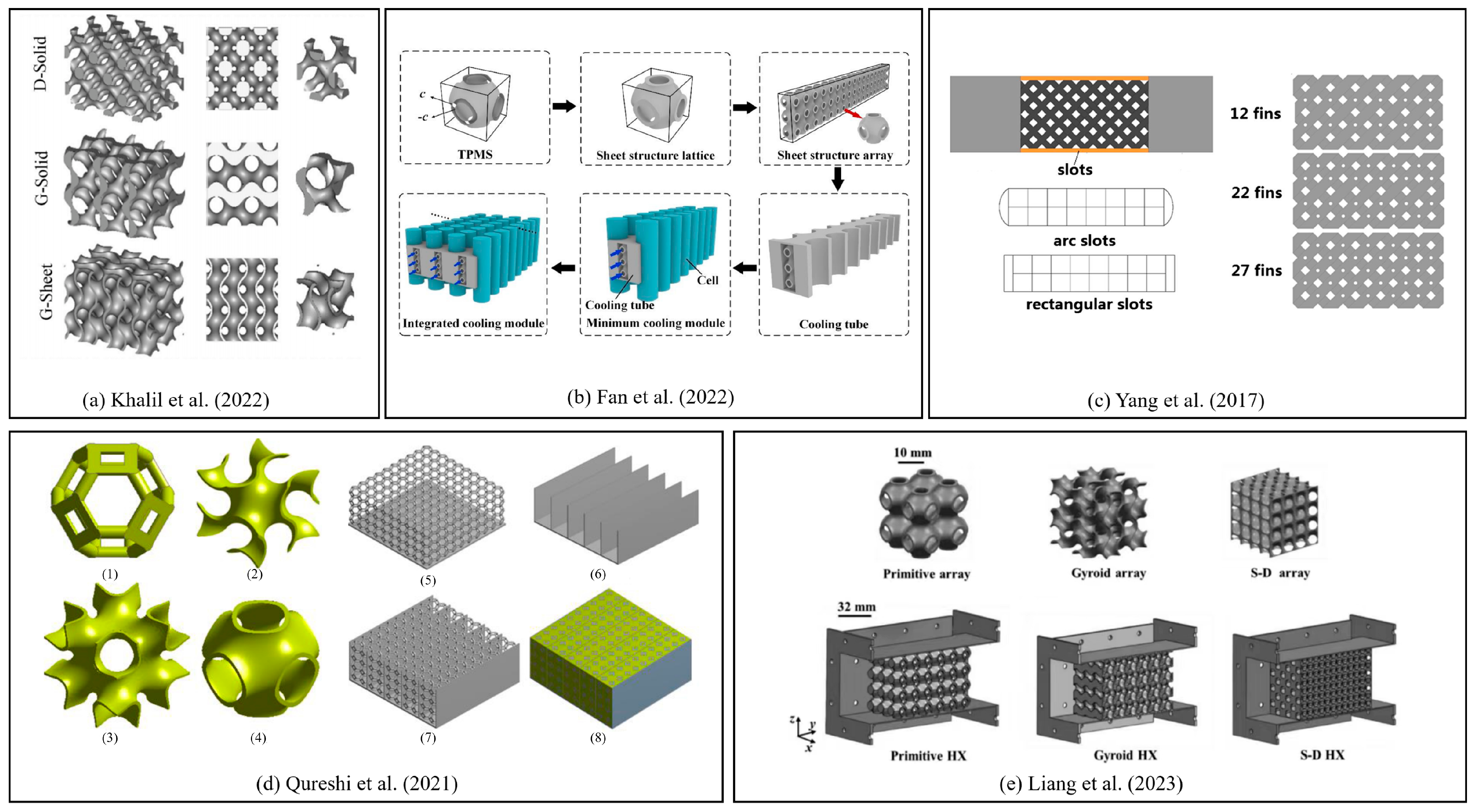
Khalil et al. [50] designed TPMS heat sinks based on the idea of similar porosity. Friction factors and pressure drops were investigated in an airflow channel. Additionally, a validated numerical model was utilized to explore the thermal performance using the areal convection heat transfer coefficient ( h A ), thermal resistance ( R t h ), Nusselt number ( N u ), thermal efficiency ( η ), and Colburn -factor. The structure of TPMS is shown in Figure 9a. According to numerical simulation results, because of the lowest surface area and largest pore size, the hydrodynamic characteristics were studied with an airflow channel and then verified by a numerical model. The results showed that form drag dominates pressure drop in a certain number range. Fan et al. [51] designed the liquid-cooled battery thermal management system based on the TPMS sheet structure for the objective of improving heat dissipation efficiency, as shown in Figure 9b. TPMS generated a smooth and continuous surface with a large surface area, which can enhance heat convection among fluid–solid interfaces. Due to the simulation, the TPMS-based sheet structure in their study significantly improved the heat transfer capability of the liquid-cooled battery thermal management system. Bu et al. [52] investigated hybrid structures of the latticework channel and slots or pin fins experimentally and numerically used for turbine blade cooling. The modified structure is shown in Figure 9c. By studying the effects of slot width, slot shape, pin fin diameter, and the configuration of latticework channels, it was found that slot reduced overall heat transfer and controlled pressure drop. On the contrary, pin fins increased these indexes. The thermal performance and heat transfer uniformity of the latticework channel could be markedly improved with the hybrid structures. Qureshi et al. [53] proposed three TPMS-based foams in a finned metal foam PCM system, and they were compared with that of the conventional metal foam, as Figure 9d depicts. The results indicated that the convective heat transfer performance of TPMS foams might be due to their cell architecture, as other input variables were kept the same. The significance of this investigation is that the application of TPMS foams in thermal energy storage systems and thermal management systems can be promising. Liang et al. [54] combined additive manufacturing and bionic structures and proposed three novel cross-flow metal heat sinks based on TPMS topology, as shown in Figure 9e. The design, fabrication, flow characteristics, and heat transfer performance of novel heat sinks were studied. The results showed that the flow path between the fluids increased due to the large-scale bifurcation flow and strong flow mixing. In contrast, the fluid flow in the conventional heat sinks has a limitation of improving heat transfer performance for the basically straight form. This structure provides a cooling scheme suited for high-Reynolds-number scenarios in aerospace applications or new energy thermal cycles.
This design combines traditional convection heat transfer with additive manufacturing, which can produce complicated TPMS structure to improve heat dissipation. This type of heat sink shows great potential under higher heat dissipation requirements.

3.5. Bionic Design

Bionic designs are also of great interest for heat sink investigators. This type of geometry is usually obtained through the observation of natural objects or bios. With a similar mechanism of heat transfer, mass transfer, or fluid control, the observed geometric features can be introduced to heat sink designs to enhance heat transfer as well as to reduce pressure drop. Such bionic concepts are achieved via shape imitation or growth rule simulations.
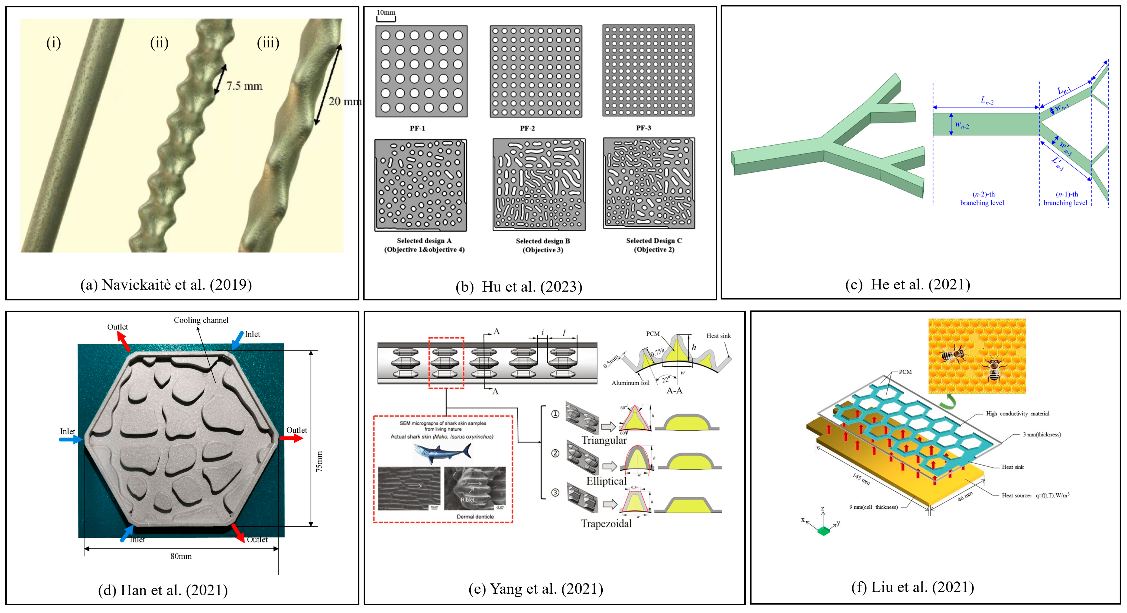
Navickaitè et al. [55], inspired by vascular heat exchangers in fish, such as tuna and opah, designed double-corrugated tube geometry for improving heat transfer with the effect of lower pressure drop. The structure and sizes of the tubes are decided by Equation (4) [55], which is developed from the tubes with an elliptical cross section:
x = R 2 A R ( s i n ( 2 π p z ) ) + R 2 y = R 2 A R ( s i n ( 2 π p z ) ) + R 2
where AR is the aspect ratio. They studied five ellipse-based tubes with varying corrugation severity and period that emulated blood vessels of fish by using additive manufacturing technology, as shown in Figure 10a. The proposed flow cross-section constantly changed along the flow path in order to continuously break up the thermal boundary layer. The double-corrugated tubes demonstrated superior thermal and global thermo-hydraulic efficiency compared to the control samples of elliptical axis tubes.
Hu et al. [56] converted the complex design heat transfer region into an overall description of 18 parameters, taking advantage of the self-organization generation equations. Equation (5) [56] was used to develop material distribution by introducing a constant into the self-organized growth equation:
f t = f ( 1 f ) f 2 f + c
where f represents phase field. They also developed a non-gradient multi-objective algorithm to optimize the topology parameters. Figure 10b shows the novel design. The results showed that the selected self-organized structure decreased the pressure drop and temperature variance, with an increase of only 3% solid volume compared to the pin-fin design. Furthermore, the optimized structures could provide a heat dissipation option with lower pressure and a more uniform temperature field. Duan et al. [48] proposed an alternative design with a double-layer Y-shaped bionic microchannel heat sink. Equation (6) [48] defines the bifurcation parameters as follows:
L i L i 1 = n 1 2 ,   L ( i + 1 ) 1 + L i + 1 L i 1 + L i = n 1 2 ,   D i + 1 D i = n 1 3 ,
where D i and D i 1 represent the ith hydraulic diameter and the ith hydraulic diameter of the bifurcation channel; L i is the length of the ith straight microchannel; and L i 1 is the ith length of the bifurcation channel. They drew the conclusion that the double-layer Y-shaped bionic microchannel with counterflow configuration exhibited better thermal performance than that of the rectangular straight microchannel. Therefore, this research shows great application potential for high-flow-rate cooling situations. He et al. [49] proposed the bionic Y-shaped fractal design and theoretically analyzed its thermal performance, as depicted in Figure 10c. According to their study, the optimal designs of symmetrical and asymmetrical fractal network heat sinks were obtained by the multi-objective optimization of the genetic algorithm. The results showed that the bionic Y-shaped fractal heat sinks decreased thermal resistance, and the pressure dropped. Increasing fractal number will effectively improve thermal performance, which indicates a further issue to discuss.
Han et al. [57] applied the topology optimization method to the bionic domain to generate two topological designs under two objectives and compared them to a conventional spider web heat sink. One objective was to minimize the temperature difference and pressure drop, and the other was to minimize the average temperature and pressure drop. They used three staggered inlets and outlets based on the spider web shape to create a uniform bottom surface temperature, as shown in Figure 10d. The topological heat sink was superior in the aspects of flow and thermal performance, thereby reducing the temperature of heat sinks. Yang et al. [58] proposed a novel heat sink inspired by a shark-skin microstructure to apply in a battery thermal management system, which was combined with axial air cooling and PCM. The new design process is shown in Figure 10e. There are a number of regularly arranged and hollow-raised structures on the surface of the shark-skin bionic heat sink, with phase change material filled in the cavities of these structures. Compared to the normal case, the cooling performance of the bionic heat sink was enhanced significantly, and the filling of PCM in the cavities of bionic structures improved the temperature consistency of the battery module. Liu et al. [59] investigated biomimetic honeycomb fins for heat transfer. The cooling system was composed of a PCM with a bionic honeycomb fin, and the pores of the fins with surrounding blanks were filled with a PCM. The entire cooling system is shown in Figure 10f. According to their numerical results, the PCM cooling system with a biomimetic honeycomb fin could reduce the battery operating temperature and increase the temperature uniformity of the PCM in the thickness direction.

4. Recommendations

Over the last few decades, substantial efforts have already been devoted to the improvement of heat sinks. Structure design played an important role in this evolution route, while its future potential remains. We can observe from history that the geometries of heat sinks have evolved from regular and simple features to those that are combined, complex, and bionic. It shows a strong trend that heat sink geometries shall go further beyond the imagination of human brains and even beyond existing mathematic concepts. With this expectation, self-organized geometries, fractal geometries, topologic optimized geometry, and iterative geometries could become the new future of heat sinks.
Besides the prospectives of heat sink geometries, it is still worth noting that the objectives of heat sink designs shall encounter emphasis on multi-objective optimization. Designs will receive the optimization of heat dissipation capability as well as temperature uniformity, pressure drop, weight, volume, and even manufacturability. This embodies the high extent of synergy between the flow fields, temperature fields, and geometries. The many goals for the design of heat sinks require us to utilize more advanced mathematical tools and manufacturing techniques to aid the design. Deep-learning and intelligent optimization algorithms could serve as good options for the future.

5. Conclusions

In this review, recent research efforts on heat sinks were summarized and analyzed. The extensive results were collected selectively from the last five years. The heat sink designs with different heat transfer rules and types of structure designs were covered. The conclusions are shown as follows:
  • The heat sinks following the principle of natural convection are mostly designed with a fin structure, since this kind of structure is a simple and effective method for passive cooling techniques. For heat sinks with pin fins, changing the pin-fin arrangement can increase the heat dissipation. For conventional heat sinks with straight ribs, adding miniature structures to the surface of the straight ribs or changing the straight ribs to curved ones exhibited a significant improvement in cooling temperature. Researchers combined empirical formulas and existing studies to optimize the parameters that have an influence on fluid flow when designing fins.
  • Most heat sinks use positive cooling management, which obeys the rule of forced convection. Introducing TPMS to microchannel heat sinks and designing manifold microchannel heat sinks are promising techniques in terms of improving heat dissipation. The generation of TPMS is based on different optimized algorithms and formulas, and these core formulas can be the focus of further research in the future.
  • Bionic structures accompanying topology optimization methods represented significant cooling effects, as well as the uniformity of temperature and low-pressure drops in heat sinks. This type of geometry could be a good research direction for the future.

Author Contributions

Investigation, J.L.; writing—original draft preparation, J.L.; writing—review and editing, L.Y.; supervision, L.Y. All authors have read and agreed to the published version of the manuscript.

Funding

This work is supported by the Shanghai Natural Science Foundation No. 22ZR1434400.

Data Availability Statement

Data are available upon request.

Conflicts of Interest

The authors declare no conflict of interest.

Nomenclature

q Heat flow density (W/m2)
A Heat transfer area (m2)
T Temperature (K)
x ,y,zCoordinates axis (m)
h Heat transfer coefficient (W/m2·K)
T w Temperature on the wall (K)
T Temperature of the fluid (K)
R t h Thermal resistance (K/W)
h A Area convection heat transfer coefficient (W/K)
N u Nusselt number
R e Reynolds number
Greek symbols
λ Heat transfer rate (W/m·K)
σ Blackbody radiation constant (W/(m2·K4))
ε Emissivity
η Thermal efficiency index
Abbreviations
HSHeat sinks
IGBTInsulated Gate Bipolar Transistor
MCHSMicrochannel heat sink
IMCHSInterrupted Microchannel heat sink
MMCHSManifold microchannel heat sink
PCMPhase change material
PVPhotovoltaic
IMCHSInterrupted microchannel heat sinks
TPMSTriply periodic minimal surfaces
MHDMagnetohydrodynamics
GOGraphene oxide
MWCNTMulti-walled carbon nanotube
CNTCarbon nanotube

References

  1. Du, P.; Zhou, Z.Q. Research progress of microchannel cooling technology for high-density microsystems. Microelectron. Comput. 2023, 1, 87–96. (In Chinese) [Google Scholar]
  2. Holman, J.P.; Lloyd, J. Heat Transfer, 10th ed.; McGraw-Hill Higher Education: New York, NY, USA, 2010; pp. 1–13. [Google Scholar]
  3. Wang, Y. Thermal Resistance Modeling and Heat Dissipation Improvement of Press-Pack IGBT. Master’s Thesis, Chong Qing University, Chongqing, China, 2021. (In Chinese). [Google Scholar]
  4. Zhang, K.; Liu, H.; Du, F.; Chen, X.; Li, B.; Hong, J. MMC-based heat sink topology optimization design for natural convection problems. Int. J. Therm. Sci. 2023, 192, 108376. [Google Scholar] [CrossRef]
  5. Muneeshwaran, M.; Tsai, M.K.; Wang, C.C. Heat transfer augmentation of natural convection heat sink through notched fin design. Int. Commun. Heat Mass Transf. 2023, 142, 106676. [Google Scholar] [CrossRef]
  6. Rao, A.K.; Somkuwar, V. Heat transfer of a tapered fin heat sink under natural convection. Mater. Today Proc. 2021, 46, 7886–7891. [Google Scholar] [CrossRef]
  7. Huang, C.-H.; Chen, W.-Y. A natural convection horizontal straight-fin heat sink design problem to enhance heat dissipation performance. Int. J. Therm. Sci. 2022, 176, 107540. [Google Scholar] [CrossRef]
  8. Feng, S.; Shi, M.; Yan, H.; Sun, S.; Li, F.; Lu, T.J. Natural convection in a cross-fin heat sink. Appl. Therm. Eng. 2018, 132, 30–37. [Google Scholar] [CrossRef]
  9. Huang, C.-H.; Chen, L. An optimized natural convection Y-shape-shifted heat sink design problem. Case Stud. Therm. Eng. 2021, 28, 101520. [Google Scholar] [CrossRef]
  10. Baobaid, N.; Ali, M.I.; Khan, K.A.; Al-Rub, R.K.A. Fluid flow and heat transfer of porous TPMS architected heat sinks in free convection environment. Case Stud. Therm. Eng. 2022, 33, 101944. [Google Scholar] [CrossRef]
  11. Krstic, M.; Pantic, L.; Djordjevic, S.; Radonjic, I.; Begovic, V.; Radovanovic, B.; Mancic, M. Passive cooling of photovoltaic panel by aluminum heat sinks and numerical simulation. Ain Shams Eng. J. 2023, 102330. [Google Scholar] [CrossRef]
  12. Obaid, A.J.; Hameed, V.M. An experimental and numerical comparison study on a heat sink thermal performance with new fin configuration under mixed convective conditions. South Afr. J. Chem. Eng. 2023, 44, 81–88. [Google Scholar] [CrossRef]
  13. Abuşka, M.; Çorumlu, V. A comparative experimental thermal performance analysis of conical pin fin heat sink with staggered and modified staggered layout under forced convection. Therm. Sci. Eng. Prog. 2023, 37, 101560. [Google Scholar] [CrossRef]
  14. Fathi, M.; Heyhat, M.M.; Targhi, M.Z.; Bigham, S. Porous-fin microchannel heat sinks for future micro-electronics cooling. Int. J. Heat Mass Transf. 2023, 202, 123662. [Google Scholar] [CrossRef]
  15. Maheswari, A.; Prajapati, Y.K. Thermal performance enhancement and optimization of double-layer microchannel heat sink with intermediate perforated rectangular fins. Int. J. Therm. Sci. 2023, 185, 108043. [Google Scholar] [CrossRef]
  16. Tang, K.; Lin, G.; Guo, Y.; Huang, J.; Zhang, H.; Miao, J. Simulation and optimization of thermal performance in diverging/converging manifold microchannel heat sink. Int. J. Heat Mass Transf. 2023, 200, 123495. [Google Scholar] [CrossRef]
  17. Pan, Y.H.; Zhao, R.; Nian, Y.L.; Cheng, W.L. Numerical study on heat transfer characteristics of a pin–fin staggered manifold microchannel heat sink. Appl. Therm. Eng. 2023, 219, 119436. [Google Scholar] [CrossRef]
  18. Zhao, Y.; Song, Y.; Zhuang, N.; Zhao, H.; Tang, X. Optimization design of surface microstructure of high-efficiency space radiation heat dissipation fins. Ann. Nucl. Energy 2023, 182, 109590. [Google Scholar] [CrossRef]
  19. Kuji, C.; Ishii, M.; Yoshikawa, R.; Mizutani, M.; Soyama, H. Fabrication of temperature-selective thermal radiation surfaces utilizing surface texturing. Precis. Eng. 2023, 82, 1–9. [Google Scholar] [CrossRef]
  20. Wang, X.; Deng, W.; Tang, X.; He, H. Experiment and simulation study on the specification parameters of finned heat sink for thermoelectric system in consideration of radiation among fins. Int. J. Therm. Sci. 2023, 185, 108097. [Google Scholar] [CrossRef]
  21. Huang, Y.; Yang, Q.; Miao, J.; Tang, K.; Zhao, J.; Huang, J.; Guo, Y. Experimental investigation on flow boiling characteristics of a radial micro pin–fin heat sink for hotspot heat dissipation. Appl. Therm. Eng. 2023, 219, 119622. [Google Scholar] [CrossRef]
  22. Kim, S.; Heu, C.; Mok, J.; Kang, S.-W.; Kim, D.R. Enhanced thermal performance of phase change material-integrated fin-type heat sinks for high power electronics cooling. Int. J. Heat Mass Transf. 2022, 184, 122257. [Google Scholar] [CrossRef]
  23. See, Y.; Ho, J.; Leong, K.; Wong, T. Experimental investigation of a topology-optimized phase change heat sink optimized for natural convection. Appl. Energy 2022, 314, 118984. [Google Scholar] [CrossRef]
  24. Singh, P.; Khanna, S.; Newar, S.; Sharma, V.; Reddy, K.S.; Mallick, T.K.; Becerra, V.; Radulovic, J.; Hutchinson, D.; Khusainov, R. Solar Photovoltaic Panels with Finned Phase Change Material Heat Sinks. Energies 2020, 13, 2558. [Google Scholar] [CrossRef]
  25. Deng, Z.; Zhang, C.; Sun, Q.; Wu, L.; Yao, F.; Xu, D. Experimental study on melting performance of phase change material-based finned heat sinks by a comprehensive evaluation. J. Therm. Anal. Calorim. 2020, 144, 869–882. [Google Scholar] [CrossRef]
  26. Kumar Marri, G.; Balaji, C. Experimental and Numerical Investigations on a Phase Change Material Based Heat Sink with Symbiotically Joined Heat Pipe. Heat Transf. Eng. 2019, 42, 23–40. [Google Scholar] [CrossRef]
  27. Azodinia, M.; Mudabbir, M.; Karimipour, A. Numerical investigation of two-phase Al2O3 nanofluid in a microchannel equipped with bump through slip flow. Eng. Anal. Bound. Elem. 2023, 155, 1028–1034. [Google Scholar] [CrossRef]
  28. Al-Rashed, A.A.; Shahsavar, A.; Entezari, S.; Moghimi, M.A.; Adio, S.A.; Nguyen, T.K. Numerical investigation of non-Newtonian water-CMC/CuO nanofluid flow in an offset strip-fin microchannel heat sink: Thermal performance and thermodynamic considerations. Appl. Therm. Eng. 2019, 155, 247–258. [Google Scholar] [CrossRef]
  29. Wang, H.; Pang, M.; Diao, Y.; Zhao, Y. Heat transfer characteristics and flow features of nanofluids in parallel flat minichannels. Powder Technol. 2022, 402, 117321. [Google Scholar] [CrossRef]
  30. Mansouri, R.; Pourrajab, R.; Behbahani, M.; Daneh-Dezfuli, A. Evaluating the convective heat transfer of graphene oxide–gold hybrid nanofluid flow in CPU. J. Therm. Anal. Calorim. 2023, 148, 5765–5776. [Google Scholar] [CrossRef]
  31. Kumar, V.; Sarkar, J. Particle ratio optimization of Al2O3-MWCNT hybrid nanofluid in minichannel heat sink for best hydrothermal performance. Appl. Therm. Eng. 2019, 165, 114546. [Google Scholar] [CrossRef]
  32. Wang, W.; Li, Y.; Zhang, Y.; Li, B.; Sundén, B. Analysis of laminar flow and heat transfer in an interrupted microchannel heat sink with different shaped ribs. J. Therm. Anal. Calorim. 2019, 140, 1259–1266. [Google Scholar] [CrossRef]
  33. Xing, J.; Han, S.; Song, Y.; An, N.; Zhou, L.; Li, L.; Zhang, H.; Du, X. Improving internal cooling performance of turbine blade with steam in channel with rhombus-patterned biomimetic ribs: A numerical investigation. Therm. Sci. Eng. Prog. 2023, 40, 101789. [Google Scholar] [CrossRef]
  34. Zhang, Q.; Wang, T.; Hou, Q.; Song, K.; Hu, W.; Wu, X. Thermal hydraulic performance augmentation by petal-shaped ribs in a two-pass cooling channel. Case Stud. Therm. Eng. 2022, 40, 102542. [Google Scholar] [CrossRef]
  35. Wang, M.; Zhang, W.; Xin, G.; Li, F.; Pu, J.H.; Du, M. Improved thermal–hydraulic performance of a microchannel with hierarchical honeycomb porous ribs. Can. J. Chem. Eng. 2022, 101, 1083–1094. [Google Scholar] [CrossRef]
  36. Jiang, W.; Zhao, J.; Rao, Z. Heat transfer performance enhancement of liquid cold plate based on mini V-shaped rib for battery thermal management. Appl. Therm. Eng. 2021, 189, 116729. [Google Scholar] [CrossRef]
  37. Rinawa, M.L.; Chauhan, P.; Sharma, R.; Poonia, A.; Singh, H.K.; Sharma, A.K.; Subbiah, R. Numerical investigation of modified fin shapes for the improved heat transfer. Mater. Today Proc. 2022, 62, 1854–1860. [Google Scholar] [CrossRef]
  38. Chiu, H.-C.; Youh, M.-J.; Hsieh, R.-H.; Jang, J.-H.; Kumar, B. Numerical investigation on the temperature uniformity of micro-pin-fin heat sinks with variable density arrangement. Case Stud. Therm. Eng. 2023, 44, 102853. [Google Scholar] [CrossRef]
  39. Saravanan, V.; Umesh, C.K. Numerical comparison for thermo-hydraulic performance of pin fin heat sink with micro channel pin fin heat sink. Sadhana 2018, 43, 100. [Google Scholar] [CrossRef]
  40. Rath, S.; Siddhartha Dash, S.K. Thermal performance of a radial heat sink with longitudinal wavy fins for electronic cooling applications under natural convection. J. Therm. Anal. Calorim. 2022, 147, 9119–9137. [Google Scholar] [CrossRef]
  41. Karlapalem, V.; Dash, S.K. On the enhancement of natural convection heat transfer with multi-branching fins. Int. J. Therm. Sci. 2023, 183, 107868. [Google Scholar] [CrossRef]
  42. Yin, H.B.; Gao, X.N. Status and Progress of Electronic Cooling Technologies. Guangdong Chem. Ind. 2013, 40, 67–68. (In Chinese) [Google Scholar]
  43. Wang, S.-L.; An, D.; Yang, Y.-R.; Zheng, S.-F.; Wang, X.-D.; Lee, D.-J. Heat transfer and flow characteristics in symmetric and parallel wavy microchannel heat sinks with porous ribs. Int. J. Therm. Sci. 2023, 185, 108080. [Google Scholar] [CrossRef]
  44. Liu, H.-L.; Fan, C.-C.; He, Y.-L.; Nobes, D.S. Heat transfer and flow characteristics in a rectangular channel with combined delta winglet inserts. Int. J. Heat Mass Transf. 2019, 134, 149–165. [Google Scholar] [CrossRef]
  45. Zhuang, D.; Yang, Y.; Ding, G.; Du, X.; Hu, Z. Optimization of Microchannel Heat Sink with Rhombus Fractal-like Units for Electronic Chip Cooling. Int. J. Refrig. 2020, 116, 108–118. [Google Scholar] [CrossRef]
  46. Memon, S.A.; Cheema, T.A.; Kim, G.M.; Park, C.W. Hydrothermal Investigation of a Microchannel Heat Sink Using Secondary Flows in Trapezoidal and Parallel Orientations. Energies 2020, 13, 5616. [Google Scholar] [CrossRef]
  47. Gilmore, N.; Timchenko, V.; Menictas, C. Manifold microchannel heat sink topology optimisation. Int. J. Heat Mass Transf. 2021, 170, 121025. [Google Scholar] [CrossRef]
  48. Duan, Z.; Xie, G.; Shen, H.; Wang, C.C. Thermal performance and entropy generation of single-layer and double-layer constructal Y-shaped bionic microchannel heat sinks. Int. J. Energy Res. 2021, 45, 9449–9462. [Google Scholar] [CrossRef]
  49. He, Z.; Yan, Y.; Feng, S.; Yang, Z.; Zhang, L.; Zhang, Z. Multi-objective optimizations on thermal and hydraulic performance of symmetric and asymmetric bionic Y-shaped fractal networks by genetic algorithm coupled with CFD simulation. Int. Commun. Heat Mass Transf. 2021, 124, 105261. [Google Scholar] [CrossRef]
  50. Khalil, M.; Ali, M.I.H.; Khan, K.A.; Abu Al-Rub, R. Forced convection heat transfer in heat sinks with topologies based on triply periodic minimal surfaces. Case Stud. Therm. Eng. 2022, 38, 102313. [Google Scholar] [CrossRef]
  51. Fan, Z.; Gao, R.; Liu, S. A novel battery thermal management system based on P type triply periodic minimal surface. Int. J. Heat Mass Transf. 2022, 194, 123090. [Google Scholar] [CrossRef]
  52. Bu, S.; Yang, L.; Qiu, H.; Luan, Y.; Sun, H. Effect of sidewall slots and pin fins on the performance of latticework cooling channel for turbine blades. Appl. Therm. Eng. 2017, 117, 275–288. [Google Scholar] [CrossRef]
  53. Qureshi, Z.A.; Elnajjar, E.; Al-Ketan, O.; Abu Al-Rub, R.; Al-Omari, S.B. Heat transfer performance of a finned metal foam-phase change material (FMF-PCM) system incorporating triply periodic minimal surfaces (TPMS). Int. J. Heat Mass Transf. 2021, 170, 121001. [Google Scholar] [CrossRef]
  54. Liang, D.; Shi, C.; Li, W.; Chen, W.; Chyu, M.K. Design, flow characteristics and performance evaluation of bioinspired heat exchangers based on triply periodic minimal surfaces. Int. J. Heat Mass Transf. 2023, 201, 123620. [Google Scholar] [CrossRef]
  55. Navickaitė, K.; Mocerino, A.; Cattani, L.; Bozzoli, F.; Bahl, C.; Liltrop, K.; Zhang, X.; Engelbrecht, K. Enhanced heat transfer in tubes based on vascular heat exchangers in fish: Experimental investigation. Int. J. Heat Mass Transf. 2019, 137, 192–203. [Google Scholar] [CrossRef]
  56. Hu, K.; Lu, C.; Yu, B.; Yang, L.; Rao, Y. Optimization of bionic heat sinks with self-organized structures inspired by termite nest morphologies. Int. J. Heat Mass Transf. 2023, 202, 123735. [Google Scholar] [CrossRef]
  57. Han, X.-H.; Liu, H.-L.; Xie, G.; Sang, L.; Zhou, J. Topology optimization for spider web heat sinks for electronic cooling. Appl. Therm. Eng. 2021, 195, 117154. [Google Scholar] [CrossRef]
  58. Yang, W.; Zhou, F.; Chen, X.; Zhang, Y. Performance analysis of axial air cooling system with shark-skin bionic structure containing phase change material. Energy Convers. Manag. 2021, 250, 114921. [Google Scholar] [CrossRef]
  59. Liu, F.; Wang, J.; Liu, Y.; Wang, F.; Yang, N.; Liu, X.; Liu, H.; Li, W.; Liu, H.; Huang, B. Performance analysis of phase change material in battery thermal management with biomimetic honeycomb fin. Appl. Therm. Eng. 2021, 196, 117296. [Google Scholar] [CrossRef]
Figure 1. The framework of the entire review and the application of heat sinks.
Energies 16 07133 g001
Figure 2. (a) The notched fin natural convection heat sink with an opening in the center region; (b) the tapered fin heat sink; (c) the designs of shift displacement of the fins of the heat sink; (d) the cross-fin heat sink; (e) the novel design of Y-shape-shifted heat sinks; (f) heat sinks of Diamond-Solid, Gyroid-Solid, and Gyroid-Sheet, showing both isometric and side view [5,6,7,8,9,10].
Energies 16 07133 g002
Figure 3. (a) The newly designed heat sink configurations; (b) conical pin-fin heat sinks of (i) staggered conical pin fins, (ii) modified staggered conical pin fins, its conical pin-fin arrangement facing the airflow direction is different from (i), (iii) parallel orientation cross-cut pin fins, and (iv) perpendicular cross-cut pin fins; (c) microchannel structures with solid fins and porous fins; (d) schematic of the novel microchannel heat sink (i) from an isometric view, (ii) from the top view of a single channel, (iii) with an intermediate rectangular fin with circle holes, (iv) from an isometric view of an intermediate rectangular fin with circle holes, and (v) with different types of holes made in the fin; (e) typical MMCHS and diverging/converging MMCHS, blue arrow is the inflow and red arrow is outflow; (f) pin fins and a partition fin [12,13,14,15,16,17].
Energies 16 07133 g003
Figure 4. (a) Three types of microstructures and flat fins; (b) (i) reference sample, (ii) surface with a periodic microstructure with pitch width in the optical wavelength range, (iii) sub-micrometer microstructure fabricated on a flat plate, (iv) surface with structure, and (iii) on top of structure (ii); (c) thermoelectric generator and the arrangement of thermoelectric legs [18,19,20].
Energies 16 07133 g004
Figure 5. (a) Microchannel with a square micro pin-fin structure and with a rectangular micro pin-fin structure; (b) modified fin-type heat sink; (c) topology-optimized solutions of θ with a temperature of 1 K; (d) (i) photovoltaic (PV) panel system, (ii) PV-phase change material (PCM) panel system, (iii) PV-finned PCM (FPCM) panel system; (e) PCM-based heat sink; (f) positions of the thermocouples on the heat sink configurations, heat sink with a heat pipe, and it with radial plate fins [21,22,23,24,25,26].
Energies 16 07133 g005
Figure 6. (a) Interrupted microchannel heat sink with four interrupted shape ribs; (b) detailed rib structures; (c) two-pass channel and a square rib, a-quarter-cylinder rib, and a petal-shaped rib; (d) microchannels with different configurations; (e) schematic of (i) a battery thermal management system based on a V-shaped rib cold plate, (ii) a cold plate with a rectangular flow channel, and (iii) a rectangular flow channel with a straight rib and V-shaped ribs [32,33,34,35,36].
Energies 16 07133 g006
Figure 7. (a) Three-dimensional representation of fins; (b) micro pin-fin arrangement with a diameter of 500: staggered type, convergent type, and convergent-divergent type; (c) top view of a single element micro channel heat sink with square pin fins and circular pin fins; (d) schematic of an isometric view of a longitudinal wavy finned radial heat sink; (e) schematic of multibranching fins: (i) vertical-base horizontal fins, (ii) vertical-base vertical fins, and (iii) horizontal-base vertical fins, the arrows indicate the direction of gravity [37,38,39,40,41].
Energies 16 07133 g007
Figure 8. (a) Two-layered microchannel heat sink with wavy walls: the parallel configuration and the symmetric configuration with solid ribs, and the parallel configuration and the symmetric configuration with porous ribs; (b) model of four kinds of composite winglets and the orientation of the angle and the pacing in the group of winglets; (c) microchannel heat sink with rhombus fractal-like units; (d) close-up view of the regular trapezoidal secondary flow, and close-up view of the parallel secondary flow [43,44,45,46].
Energies 16 07133 g008
Figure 9. (a) Isometric view, front view, and corresponding unit cell of the TPMS heat sinks; (b) analysis model of the TPMS-based battery thermal management system; (c) latticework channels with slots or pin fins; (d) foams used in this study and the three configurations; (e) 2 × 2 × 2 TPMS test array, and sectional view in the middle yz-plane of each TPMS heat sink [50,51,52,53,54].
Energies 16 07133 g009
Figure 10. (a) The 3D printed tubes: (i) the straight reference tube, (ii) double-corrugated tube with AR = 2.0 and p = 7.5 mm, (iii) double-corrugated tube with AR = 2.2 and p = 20.0 mm; (b) geometry structure of pin-fin heat sinks and optimized self-organization heat sinks; (c) the generalized bionic Y-shaped fractal networks; (d) the experimental heat sink; (e) the structure diagram of bionic heat sinks and the battery module; (f) phase change material battery cooling system with a biomimetic fin [49,55,56,57,58,59].
Energies 16 07133 g010
Table 1. The microchannel heat sinks in this review are listed.
The AuthorStudy MethodsHeat Sinks Design Features
Fathi et al. [14]Simulation methodHeat sinks with parallel solid fins and porous fins.
Maheswari et al. [15]Simulation methodDouble-layer MCHS with different holes cut in the fins.
Tang et al. [16]Simulation methodApplied diverging/converging channels to the typical microchannel structure.
Pan et al. [17]Simulation methodA pin-fin staggered MMCHS.
Azodinia et al. [27]Simulation methodTwo-phase Al2O3 nanofluid flow in a microchannel.
Al-Rasheda et al. [28]Simulation methodNon-Newtonian water-CMC/CuO nanofluid flow in an offset strip-fin microchannel heat sink.
Mansouri et al. [30]Experimental methodHybrid nanofluid containing graphene oxide (GO)-gold/water and GO/water nanofluid in cooling a computer’s CPU.
Saravanan et al. [39]Simulation methodCombined the structure of square and circular pin fins to the MMCHS.
Wang et al. [43]Simulation methodDouble-layered MMCHS with parallel and symmetric wavy porous fins.
Liu et al. [44]Simulation and experimental methodsDelta winglet generators inserted in a rectangular microchannel.
Zhuang et al. [45]Simulation and experimental methodsA novel structure of MCHS with rhombus fractal-like units.
Memon et al. [46]Simulation methodIntroduced secondary flow channels to the walls between adjacent mainstream microchannels.
Gilmore et al. [47]Simulation methodApplied topology optimization to design a multi-objective 3D conjugate heat transfer model.
Duan et al. [48]Simulation methodA Y-shaped bionic MMCHS.
He et al. [49]Simulation methodA bionic Y-shaped fractal heat sink obtained by the multi-objective optimization of the genetic algorithm.
Disclaimer/Publisher’s Note: The statements, opinions and data contained in all publications are solely those of the individual author(s) and contributor(s) and not of MDPI and/or the editor(s). MDPI and/or the editor(s) disclaim responsibility for any injury to people or property resulting from any ideas, methods, instructions or products referred to in the content.