Article

P-Doped Modified Porous Carbon Derived from ZIF-8 for Enhanced Capacitive Performance

School of Electric Power, Civil Engineering and Architecture, Shanxi University, Taiyuan 030006, China
*
Author to whom correspondence should be addressed.
Energies 2023, 16(21), 7232; https://doi.org/10.3390/en16217232
Submission received: 8 September 2023 / Revised: 9 October 2023 / Accepted: 20 October 2023 / Published: 24 October 2023

Abstract

:
Porous carbon materials derived from ZIF-8 have attracted extensive research attention on account of their large surface area, tunable mesoporosity and abundant nitrogen content. However, directly carbonized ZIF-8 usually suffers from a low electronic conductivity, poor wettability and relatively low mesoporosity, which severely restricts their capacitive performance. Herein, P-doped modified carbon materials derived from ZIF-8 (ZPCs) were synthesized by using nontoxic phytic acid as a phosphorus source, followed by carbonization at high temperature. Benefiting from its relatively high specific surface area of 911.7 m2 g−1 and higher ratio of mesopores, as well as N, O and P doping, ZPC-1000 delivers the largest specific capacity, up to 219.4 F g−1 at 1 A g−1, among the prepared samples and an outstanding cycle span, retaining 100% capacity after 2000 cycles at 5 A g−1. In this work, we highlight the strategy of constructing a synergistic effect between high mesoporosity and heteroatom doping, which can greatly boost the capacitive performance of carbon materials.

1. Introduction

Supercapacitors are one of the most attractive devices for energy storage since they possess an excellent power density, fast charge/discharge speed, flexible operating temperatures and stable cycle life. Thus, they have been identified as the optimal choice to span the gap between traditional capacitors and rechargeable batteries [1,2,3,4]. Generally, depending on the charge storage mechanism, supercapacitors can be divided into three categories: electric double layer capacitors (EDLCs), pseudocapacitors and hybrid supercapacitors [3,5]. Pseudocapacitors store charge based on the fast and reversible faradaic reaction with electron transfer, while EDLCs utilize electrostatic adsorption at the electrode–electrolyte interface [1,3]. In addition, hybrid supercapacitors, with the combined features of EDLCs and pseudocapacitors, mainly depend on a capacitor-type electrode, such as various carbon materials or polymers, and a battery-type electrode, including alkali metals or multivalent metals, to store electrical charge [5,6,7,8]. Although pseudocapacitors possess the merit of a high specific capacitance, they always suffer a low power density due to the relatively slow dynamic process of the faradaic reaction [3]. By contrast, EDLCs motivate widespread concerns owing to their greater cyclic stability [5]. In nature, electrode materials determine the charge storage mechanism and the electrochemical performance of supercapacitors. Various carbon-based materials, including carbon nanotubes [9], graphene [10], activated carbon [11] and carbon fiber [12] are usually employed as electrode materials in EDLCs, which benefit from their unique properties, such as abundant availability, cost-effectiveness, excellent stability, environmental friendliness and good electrical conductivity [13].
Recently, porous carbon derived from metal organic frameworks (MOF) such as ZIF-8 have been commonly utilized as supercapacitor electrode materials, since they can inherit the merits of MOF, including a huge surface area, high nitrogen content and tunable porous structure [3,14], and have a great advantage as candidates over other materials for improving capacitive performance. In particular, nitrogen doping can ameliorate the conductivity and surface wettability of carbon materials and induce extrinsic pseudocapacitance [15,16]. For instance, Lin’s group reported that the flexible supercapacitor assembled with carbonized ZIF-8 showed a potential window of 0.8 V and a high specific capacitance of 214.8 F g−1 at 20 mV s−1 [17]. Moreover, open-door nanoporous carbon was fabricated by the pyrolysis of salt-filled ZIF-8 and showed a capacitance value of 574.9 F g−1 at 0.5 A g−1 [18]. However, ZIF-8 derived carbon materials generally show a relatively low electronic conductivity, bad wettability and poor pore accessibility, which are not conducive to ion transfer and diffusion [17,18,19]. More significantly, the inherently microporous structure originating from ZIF-8 leads to the low utilization efficiency of the microporous surface and is further reflected in the inability to retain a high specific capacitance at a high sweep rate [20]. An effective strategy to modify porous carbon to enhance the capacitive performance involves two approaches. On the one hand, increasing mesoporosity in activated carbon can facilitate the entrance and diffusion of electrolyte ions through the pores. For instance, MOFs@Wood-derived composites were synthesized and delivered a high specific capacitance of 12.52 F/cm2 [19]. To construct a 3D interconnected architecture, ZIF-8 was grown on the surface of melamine foam and the as-obtained PNC/CF achieved a high energy density and superior cycling stability [14]. On the other hand, the incorporation of another heteroatom into the carbon framework, such as P, O and S, can form a coupling effect between heteroatoms and further improve the physicochemical characteristics of carbon materials [21]. Theoretically, inducing P into a carbon skeleton can effectively enhance the charge delocalization or asymmetric spin density and thereby boost the electrochemical supercapacitive performance [21]. For example, N, P co-doped carbon nanosheets were fabricated using NH4H2PO4 as the co-dopant and showed a high specific capacitance (314 F g−1) and outstanding rate capability [22]. Likewise, N, P co-doped porous carbon with a high specific area of 1635 m2 g−1 displayed a high capacitive performance of 490 F g−1 and an extraordinary cycle life [23].
In this work, with phytic acid as a phosphorus source, a P-doped modified porous carbon derived from ZIF-8 (ZPC) was fabricated by the carbonization of ZIF-8 under high temperature. The carbonization temperature is a decisive factor in constructing a mesoporous structure and introducing a heteroatom into a carbon skeleton. Owing to its relatively high specific surface area of 911.7 m2 g−1, high ratio of mesopores and multi-heteroatom doping, the optimal ZPC-1000 electrode exhibits a substantial specific capacitance (219.4 F g−1) and long durability.

2. Materials and Methods

2.1. Materials

Zinc nitrate (Zn(NO3)2·6H2O, LOT: Z833285), 2-methylimidazole (C4H6N2, LOT: M813135), phytic acid (C6H18O24P6, LOT: P816021) and potassium hydroxide (KOH) were purchased from Shanghai Macklin Biochemical Co., Ltd. (Shanghai, China) Acetylene black and polytetrafluoroethylene (PTFE, 60%) were obtained from Aladdin Chemical Reagent Co., Ltd., Shanghai, China.

2.2. Preparation of P-Doped Modified Porous Carbon Derived from ZIF-8 (ZPC)

In detail, zinc nitrate (5 mmol) and 2-methylimidazole (50 mmol) were dissolved in deionized water (20 mL) separately and stirred for 30 min at room temperature. Then, phytic acid (50 μL) was added into the mixed solutions. After stirring for 6 h, the resulting product was washed repeatedly with deionized water and then dried at 60 °C for 12 h. The as-prepared product was subsequently carbonized at 700, 800, 900 and 1000 °C for 2 h in N2 atmosphere, respectively. Finally, the obtained samples were denoted as ZPC-700, ZPC-800, ZPC-900 and ZPC-1000, respectively. Additionally, ZC-1000 was obtained by the direct pyrolysis of ZIF-8 at 1000 °C.

2.3. Characterization

X-ray diffraction (XRD) was executed using a Brucker Advance D8 diffractometer with Cu Kα irradiation (λ = 1.5418 Å). Raman spectra of ZPCs samples were collected by Raman spectrometer (Thermofisher Dxr2xi, Thermo Fisher Scientific, Waltham, MA, USA) with a 532 nm laser source. The microstructure and surface morphology of ZPCs samples were characterized by field-emission scanning electron microscopy (FESEM, ThermoFisher Quattro S, Thermo Fisher Scientific, Waltham, MA, USA) and a transmission electron microscope (TEM, JEM-2100F, JEOL, Tokyo, Japan). The nitrogen adsorption–desorption tests were implemented on a Micromeritics ASAP 2460 volumetric adsorption analyzer. The specific surface area (SBET) was obtained by the Brunauer–Emmett–Teller (BET) method and the pore size distribution was estimated by the Barrett–Joyner–Halenda (BJH) method. The total pore volume (Vt), mesoporous volume (Vmeso) and microporous volume (Vmicro) were analyzed by density functional theory (DFT). The elemental compositions of ZPCs samples were investigated by X-ray photoelectron spectroscopy (Thermo Fisher Scientific K-alpha, Thermo Fisher Scientific, Waltham, MA, USA) with Al Kα irradiation.

2.4. Electrochemical Measurements

The capacitive performance of the ZPCs samples was evaluated using a three-electrode CHI760E electrochemical workstation (Chenhua, Shanghai, China) in 6 M KOH. The Pt sheet and Hg/HgO electrode were used as counter and reference electrodes, respectively. The working electrode was fabricated by mixing ZPCs samples, PTFE and acetylene black in a mass ratio of 7.5:1:1.5, dissolving the mixture in ethanol and then casting the slurry on nickel foam (1 × 1 cm2). After drying, the pasted electrodes were pressured for 5 min under 10 MPa pressure. The loading mass of the active materials is around 6 mg. The cyclic voltammetry (CV) curve was measured at increasing scan rates with the voltage ranging from −1 to 0 V. A galvanostatic charging–discharging (GCD) curve was measured at various current densities over a voltage of −1 to 0 V. Cyclic stability was assessed via a charge–discharge test at 5 A g−1. An electrochemical impedance spectroscopy (EIS) of the ZPCs samples was conducted within a frequency range from 10−2 to 105 Hz.
The specific capacitance C (F g−1) of electrodes can be calculated according to the following equation [24,25]:
C = I × t V × m
where I (A) is the discharge current, ∆t (s) represents the discharge time, ∆V (V) refers to the discharge voltage range and m is the mass of the active material.

3. Results

3.1. Morphological and Structural Characterization

Figure 1a,b are the FESEM images of ZC-1000 and ZPC-1000, respectively. The morphology of the ZC-1000 sample is an irregular block shape. On the contrary, the ZPC-1000 sample with the addition of phytic acid exhibits an interconnected network of particles whose pore channels facilitate the transfer and diffusion of ions; this improves the electrochemical performance. In Figure 1c,d, the randomly distributed worm-like structure observed in TEM images reveals the existence of amorphous carbon in ZPC-1000. The crystalline structure of the ZPCs samples was examined via XRD in Figure 1e. In the XRD patterns, two broad peaks corresponding to the 002 and 100 diffractions of graphitic carbon (JCPDS No. 41-1487) were observed at around 25° and 43°, confirming the amorphous nature of the synthesized carbon materials [26,27].
Based on Scherrer’s formula [28,29], the calculated crystalline sizes are 3.68, 3.41, 3.65, 3.8 and 3.62 nm for ZC-1000, ZPC-700, ZPC-800, ZPC-900 and ZPC-1000, respectively. Obviously, the relatively small crystalline size of ZPC-1000 indicates a higher degree of disorder, which is attributed to heteroatom doping [4]. As the carbonization temperature increases, the peak centered at 25° shifts to the low angle region, demonstrating more defects and a higher degree of graphitization [16,30,31]. The disorder degree of the ZPCs samples can be further analyzed using the Raman spectrum. As presented in Figure 1f, the two prominent peaks centered at 1350 cm−1 and 1590 cm−1 are assigned to the D and G bands of carbon, respectively [32]. The D band corresponds to the defective carbon of turbostratic carbon layers, while the G-band represents the C–C bond stretching vibrations originating from the sp2 hybrid carbon atoms [33]. The ID/IG is usually utilized to estimate the defect degree. The calculated ratio of ID/IG for ZC-1000, ZPC-700, ZPC-800, ZPC-900 and ZPC-1000 are 0.85, 0.74, 0.89, 0.83 and 0.85, respectively. ZPC-700 shows the smallest ID/IG value among these samples, which might be attributed to its dense poreless structure. Compared to ZPC-700, the higher ID/IG values of ZPC-800, ZPC-900 and ZPC-1000 reflect the existence of more defects and more pores in their carbon frameworks, which favor the diffusion of ions and an increase in the abundance of adsorption sites. Additionally, the ID/IG ratio of ZC-1000 is very close to that of ZPC-1000, confirming the influence of activating temperature on the formation of lattice disorder in carbon materials.
To analyze the surface elemental composition of ZPCs samples, XPS measurement was carefully carried out (Figure 2, Table S1 and Figures S1–S4). The N 1s, O 1s and P 2p peaks can be observed in the XPS survey spectrum of the ZPC-1000 sample (Figure 2a), confirming that N, O and P were smoothly introduced into the carbon skeleton of ZPC-1000. As summarized in Table S1, all samples contain a small amount of Zn, which is probably due to the fact that Zn is not completely volatilized during the carbonization process. The elemental contents of N, O, P and Zn for ZPCs samples significantly decreased as the carbonization temperature increased, verifying that the unstable functional groups of samples gradually decompose under high-temperature conditions. The C 1s peak of ZPC-1000 can be fitted into five peaks approximately centered at 284.8, 285.5, 286.7, 289.0 and 291 eV (Figure 2b), which are related to the C–C/C=C, C–N/C–P, C–O, C=O and π−π* groups, respectively [34,35]. Figure 2c displays the N 1s spectrum of ZPC-1000; the peaks at 398.5, 400.09 and 400.9 eV are assigned to pyridinic N, pyrrolic N and quaternary N, respectively [36]. In fact, the electrical conductivity of carbon materials is effectively enhanced by quaternary N, causing an acceleration of charge transfer kinetics, while pyridinic N and pyrrolic N can increase the surface pseudocapacitance [23,37]. Likewise, the O 1s XPS spectrum exhibits three fitted peaks at 531.3 eV (C=O), 532.3 eV (C–OH) and 533.8 eV (C–O) (Figure 2d), which are beneficial for the reduction in the interface resistance and for the efficient diffusion of electrolyte ions [31]. The P 2p spectrum of ZPC-1000 in Figure 2e demonstrates two types of phosphorus-containing functional groups: P–C (132.8 eV) and P–O (134.0 eV) [23], which can enhance the surface wettability of activated carbon and decrease the charge transfer resistance [38]. Based on the above analysis, N, O and P co-doping would be favorable to modify the surface characterization of porous carbon and thus boost the electrochemical capacitive performance of ZPCs electrodes. Additionally, when the carbonization temperature rises from 700 °C to 1000 °C, the surface carbon contents of ZPCs as obtained via XPS significantly increase (Figure 2f), implying the better conductivity and enhanced capacitive performance of ZPC-1000.
To further evaluate the porous characteristics of the ZPCs samples, the N2 adsorption–desorption isotherms are collected as displayed in Figure 2g. The ZPC-700 sample displays an extremely low N2 adsorption capacity, verifying its nonporous structure. Compared to ZPC-700, the other samples have the composite isotherms of type Ⅰ and Ⅳ. Additionally, these isotherms rise sharply at a low pressure of P/P0 < 0.05 and exhibit an obvious hysteresis loop at medium pressure (P/P0 > 0.45), illustrating the coexistence of micropore and mesopore structures [37,38]. In ZPC-900, the isotherms show a slight rise at high pressure (P/P0 > 0.9), signifying the existence of a small number of macropores [37,38]. As listed in Table 1, ZPC-700 shows an extremely small SBET of 55.4 m2 g−1, in line with its nonporous character. At an elevated carbonization temperature, the SBET of samples exhibits a tendency to increase (Table 1). Of note, the SBET of ZPC-900 (698.8 m2 g−1) is slightly smaller than that of ZPC-800 (836.1 m2 g−1) as a result of the collapse of micropores at a high temperature [33,39]. When the temperature increased to 1000 °C, ZPC-1000 possessed the highest SBET of 911.7 m2 g−1, which may be due to the reformation of new micropores and mesopores [40]. Meanwhile, ZC-1000 also has a similar SBET (891.7 m2 g−1) to ZPC-1000, which is testament to the vital role of the carbonization temperature. Obviously, in Figure 2h, there are hardly any pores for ZPC-700, in accordance with its low N2 adsorption capacity. In ZPC-800, the presence of an evident peak located at 60 nm reveals macropores, resulting in a larger avenge pore size of 5.29 nm (Table 1). Apart from ZPC-700, other samples present a multiscale porous structure consisting of micropores and mesopores. In general, the micropores make a more significant contribution to enlarging SBET and enhancing the charge storage capability; meanwhile, the presence of mesopores can provide a smooth charge transfer channel for ions and therefore facilitate ion diffusion [37,38,41]. In particular, the proper ratio of mesopores to micropores has a crucial influence on the transport of electrons [31], which is likely to determine the specific capacity of a carbon electrode. To assess the role of mesoporosity, the relative proportions of mesopores and micropores are summarized in Figure 2i. Evidently, ZPC-1000 has a comparatively larger pore volume and the highest ratio of mesopore to micropore, which benefit the ion transport rate and ameliorate the capacitive performance of carbon materials.

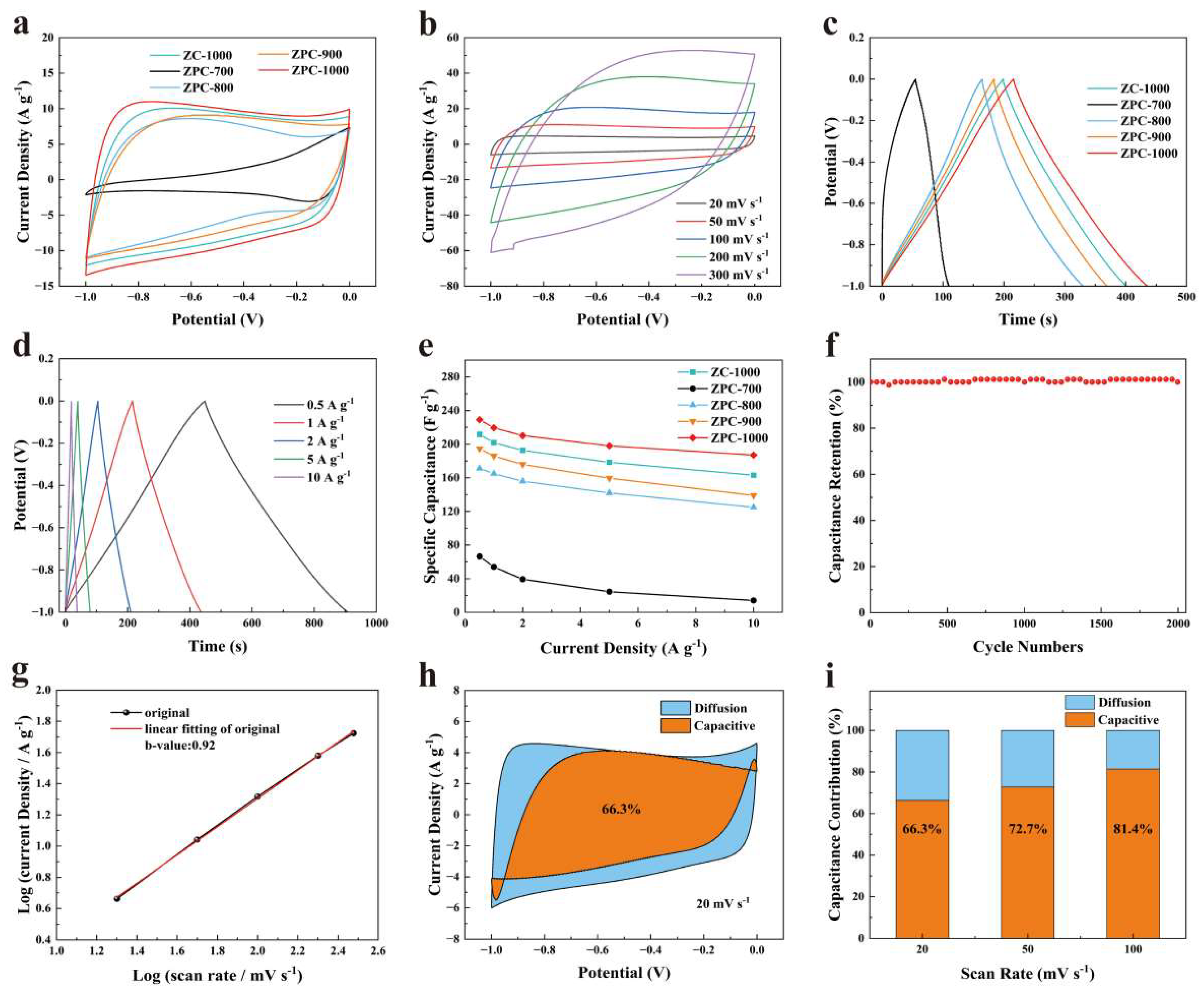
3.2. Electrochemical Performance of ZPCs

Figure 3a displays the CV curves of the ZPCs samples tested at 50 mV s−1. Obviously, the smallest CV integral area for ZPC-700 presents a poor charge storage capacity, which results from its low SBET and dense structure. Compared with ZPC-700, the CV curves of other samples show a similar near-rectangular shape, suggesting typical EDLC behaviors. The relative areas enclosed by the CV curves are 15.8, 3.46, 12.3, 13.5 and 18.0 for ZC-1000, ZPC-700, ZPC-800, ZPC-900 and ZPC-1000, respectively. Obviously, the values of the areas gradually increase as the carbonization temperature increases from 700 °C to 1000 °C, and the area of ZC-1000 is much larger than that of ZPC-900, which ascertains the impact of carbonization temperature in elevating SBET and creating hierarchical porosity. In comparison, ZPC-1000 possesses the largest area enclosed by the CV curve (Figure 3a and Figure S5), demonstrating its superior surface capacitance, which is ascribed to its higher SBET, high proportion of mesopores and characteristic of N, O and P co-doping. Moreover, as depicted in Figure 3b and Figure S6, compared to other samples, ZPC-1000 exhibits a quasi-rectangular-shaped CV curve without obvious deviation at elevated scanning rates, thereby confirming its favorable rate performance and fast charge transfer capability [42]. Meanwhile, the areas of the CV curves show an increasing tend with increments in scan rates. These test results ascertain excellent fast response and rate capabilities, which are due to abundant mesopores and surface heteroatom doping [31]. Moreover, the GCD curves of ZPCs samples in Figure 3c show symmetric triangular shapes with slight deformation, also suggesting EDLC behaviors [19,33]. Obviously, the discharge times of the ZPCs increase with the increasing carbonization temperature. Among them, ZPC-1000 has the longest discharge time, signifying its most superior reversible capacitance, in accordance with the CV test results. According to the GCD curves, the specific capacitances calculated based on Equation (1) are 201.8, 54, 165, 185.9 and 219.4 F g−1 for ZC-1000, ZPC-700, ZPC-800, ZPC-900 and ZPC-1000 at 1 A g−1, respectively. Particularly, ZPC-900, which has lesser SBET and heteroatom contents in comparison with ZPC-800, instead exhibits a higher electrochemical performance, which may be due to its better electrical conductivity thanks to its high graphitization [43]. This high specific capacitance value reported for ZPC-1000 is competitive with that recently reported for carbon materials derived from ZIF-8 (Table 2). As mentioned previously, the ZPC-1000 sample exhibited the optimal capacity due to its larger SBET and high ratio of mesopores to micropores, which provides active sites for ion adsorption and accelerates ion diffusion and transport. N, O and P doping can also enhance the electrical conductivity and surface hydrophily of ZPC-1000, and thus make a vital contribution to elevating its specific capacitance. Moreover, the lower charge transfer and diffusive resistance of ZPC-1000 are beneficial for reducing transfer barriers and therefore boosting the electrochemical performance of activated carbon (Figure S7).
As shown in Figure 3d, as the current density was raised to 10 A g−1, the discharge time decreased continuously, as diffusing into the internal space of pores at a high current density is very difficult for electrolyte ions [52]. However, even at 10 A g−1, the triangular shape of the GCD curve for ZPC-1000 stays unchanged, confirming its ideal capacitive behavior and outstanding rate performance [53]. Furthermore, the calculated specific capacitance of ZPCs samples is presented in Figure 3e. The capacitance retention of 81.66% for ZPC-1000 is better than that for ZC-1000 (77.07%), ZPC-700 (21.05%), ZPC-800 (72.99%) and ZPC-900 (71.47%), further verifying its excellent rate capability performance. The electrochemical stability of ZPC-1000 was measured over 2000 cycles at 5 A g−1 (Figure 3f). After 2000 cycles, its specific capacitance retention stays at 100%, demonstrating the excellent cycling performance of ZPC-1000 and its great potential for application as a supercapacitor.
To estimate the effects of porous structure on the electrochemical kinetics of the charge/discharge mechanism, the relationship of current density (i) and scan rate (v) can be inferred according to Equations (2) and (3) [45,54].
i = a v b
l o g ( i ) = l o g ( a ) + b l o g ( v )
where a and b are adjustable parameters. A b value of 0.5 represents a diffusion-controlled process; otherwise, the b value approaches 1, indicating a surface-controlled charge storage mechanism [10,54]. As illustrated in Figure 3g, the calculated b value of ZPC-1000 is 0.92, indicating that the charge storage process may be governed by a surface-controlled mechanism. According to the Dunn method [54,55], the total charge may be separated into surface-controlled electrical double-layer capacitance and diffusion-controlled pseudocapacitance. The contribution of surface-controlled capacitance can be further determined using the following equation [54,55]:
i = a 1 v + a 2 v 1 / 2
where a1v and a2v1/2 represent the capacitive and diffusion contributions, respectively. Here, a1 and a2 are constants, and can be obtained on the basis of Equation (5).
i / v 1 / 2 = a 1 v 1 / 2 + a 2
In Figure 3h, for ZPC-1000, the surface-controlled capacitance (orange regions) is 66.3% of the total capacitance at a low scan rate of 20 mV s−1, demonstrating a surface-controlled mechanism, which is induced by its hierarchical porosity and heteroatoms doping. Furthermore, the percentage surface capacitance increases from 66.3% to 81.4% as the scan rate is increased, suggesting the better ion storage capacity of ZPC-1000 [56]. In fact, at a high scan rate, it is difficult for electrolyte ions to penetrate into micropores, and the surface capacitive behavior is mainly determined by the adsorption of ions on mesoporous surfaces, thus resulting in a reduction in diffusion-controlled capacitance [57].

4. Conclusions

In summary, P-doped modified porous carbon derived from ZIF-8 (ZPCs) with a high mesoporosity, heteroatom co-doping of N, O, and P and a large SBET of 911.7 m2 g−1 was synthesized via the carbonization of ZIF-8 with the addition of phytic acid. The obtained activated carbon displays a relatively high specific capacitance of 219.4 F g−1 at 1A g−1, which can potentially compete with most porous carbon materials derived from ZIF-8. Moreover, the capacitance retention of the ZPC-1000 sample may reach 100% after 2000 cycles. With the merits of high mesoporosity and heteroatom doping of N, O and P, the prepared ZPCs may be a competitive candidate for use as an electrode material.

Supplementary Materials

The following supporting information can be downloaded at: https://www.mdpi.com/article/10.3390/en16217232/s1, Table S1: The surface elemental composition of all samples calculated using XPS results; Figure S1: (a–d) C 1s, N 1s, O 1s and P 2p XPS spectra of ZPC-700; Figure S2: (a–d) C 1s, N 1s, O 1s and P 2p XPS spectra of ZPC-800; Figure S3: (a–d) C 1s, N 1s, O 1s and P 2p XPS spectra of ZPC-900; Figure S4: (a–c) C 1s, N 1s and O 1s XPS spectra of ZC-1000; Figure S5: (a) The CV curve of bare nickel foam at a scan rate of 50 mV s−1. (b) The comparison of CV curves for ZPC-1000 and bare nickel foam at the same scan rates; Figure S6: (a–d) The CV curves of ZPC-700, ZPC-800, ZPC-900 and ZC-1000 at different scan rates; Figure S7: Nyquist plots of all samples.

Author Contributions

Conceptualization, C.G. and G.L.; methodology, C.G. and G.L.; resources, C.G.; data analysis, C.G., G.L. and Y.W.; formal analysis, C.G. and J.W.; funding acquisition, C.G., X.W. and Y.N.; writing—original draft, C.G.; supervision, X.W., Y.N. and J.W. All authors have read and agreed to the published version of the manuscript.

Funding

This research was supported by Scientific and Technological Innovation Programs of Higher Education Institutions in Shanxi (STIP), grant number 2021L014, and the Shanxi Applied Basic Research Program, grant numbers 20210302124126 and 202103021223031.

Data Availability Statement

Not applicable.

Conflicts of Interest

The authors declare no conflict of interest.

References

  1. Mohanty, A.; Jaihindh, D.P.; Fu, Y.P.; Senanayak, S.P.; Mende, L.S.; Ramadoss, A. An extensive review on three dimension architectural metal-organic frameworks towards supercapacitor application. J. Power Sources 2021, 488, 229444. [Google Scholar] [CrossRef]
  2. Peng, Y.; Xu, J.; Xu, J.M.; Ma, J.; Bai, Y.; Cao, S.; Zhang, S.T.; Pang, H. Metal-organic framework (MOF) composites as promising materials for energy storage applications. Adv. Colloid Interfac. 2022, 307, 102732. [Google Scholar] [CrossRef] [PubMed]
  3. Khokhar, S.; Anand, H.; Chand, P. Current advances of nickel based metal organic framework and their nanocomposites for high performance supercapacitor applications: A critical review. J. Energy Storage 2022, 56, 105897. [Google Scholar] [CrossRef]
  4. Dar, M.A.; Dinagaran, S.; Govindarajan, D.; Ahamed, S.R.; Habib, F.; Siva, C.; Moholkar, A.V.; Ahmad, Z.; Yatoo, M.A. Snx-0MnxS nanomaterial based electrodes for future-generation supercapacitor and data storage devices. J. Alloys Compd. 2023, 958, 170523. [Google Scholar] [CrossRef]
  5. Lokhande, P.E.; Kulkarni, S.; Chakrabarti, S.; Pathan, H.M.; Sindhu, M.; Kumar, D.; Singh, J.; Kumar, A.; Mishra, Y.K.; Toncu, D.C.; et al. The progress and roadmap of metal-organic frameworks for high-performance supercapacitors. Coord. Chem. Rev. 2022, 473, 214771. [Google Scholar] [CrossRef]
  6. Gao, X.; Wu, H.Y.; Su, C.; Lu, C.M.; Dai, Y.H.; Zhao, S.Y.; Hu, X.Y.; Zhao, F.J.; Zhang, W.; Parkin, I.P.; et al. Recent advances in carbon-based nanomaterials for multivalent-ion hybrid capacitors: A review. Energy Environ. Sci. 2023, 16, 1364. [Google Scholar] [CrossRef]
  7. Vlad, A.; Singh, N.; Rolland, J.; Melinte, S.; Ajayan, P.M.; Gohy, J.F. Hybrid supercapacitor-battery materialsfor fast electrochemical charge storage. Sci. Rep. 2014, 4, 4315. [Google Scholar] [CrossRef]
  8. Du, W.; Bai, Y.L.; Xu, J.Q.; Zhao, H.B.; Zhang, L.; Li, X.F.; Zhang, J.J. Advanced metal-organic frameworks (MOFs) and their derived electrode materials for supercapacitors. J. Power Sources 2018, 402, 281–295. [Google Scholar] [CrossRef]
  9. Zhu, S.; Chang, Y.Z.; Hou, W.J.; Li, Y.P.; Ni, J.F.; Han, G.Y. Molten-salt directed mesopore engineering of carbon nanotubes for energetic quasi-solid-state supercapacitors. Carbon 2022, 200, 75–83. [Google Scholar] [CrossRef]
  10. Khan, M.S.; Jhankal, D.; Shakya, P.; Sharma, A.K.; Banerjee, M.K.; Sachdev, K. Ultraslim and highly flexible supercapacitor based on chemical vapor deposited nitrogen-doped bernal graphene for wearable electronics. Carbon 2023, 208, 227–237. [Google Scholar] [CrossRef]
  11. Zhang, W.; Li, W.X.; Li, S. Molten salt assisted self-activated carbon with controllable architecture for aqueous supercapacitor. J. Mater. Sci. Technol. 2023, 156, 107–117. [Google Scholar] [CrossRef]
  12. Zhou, L.F.; You, X.Y.; Wang, L.J.; Qi, S.J.; Wang, R.C.; Uraki, Y.; Zhang, H.J. Fabrication of graphitized carbon fibers from fusible lignin and their application in supercapacitors. Polymers 2023, 15, 1947. [Google Scholar] [CrossRef] [PubMed]
  13. Escobar, B.; Martinez-Casillas, D.C.; Perez-Salcedo, K.Y.; Rosas, D.; Morales, L.; Liao, S.J.; Huang, L.L.; Shi, X. Research progress on biomass-derived carbon electrode materials for electrochemical energy storage and conversion technologies. Int. J. Hydrogen Energy 2021, 46, 26053–26073. [Google Scholar] [CrossRef]
  14. Shi, C.J.; Li, S.; Pan, Y.; Guo, L.; Wang, Y.Z. Self-standing porous N doped carbon/carbon foam for high-performance supercarpacitor. Diam. Relat. Mater. 2020, 110, 108138. [Google Scholar] [CrossRef]
  15. Zhang, H.R.; Wang, Z.X.; Li, X.X.; Zhu, M.X.; Zhou, J.P. A flake-like N, O co-doped hierarchical porous carbon derived from chitin with enhanced supercapacitance. J. Alloys Compd. 2022, 924, 166534. [Google Scholar] [CrossRef]
  16. Hsiao, Y.J.; Lin, L.Y. Efficient pore engineering in carbonized zeolitic imidazolate Framework-8 via chemical and physical methods as active materials for supercapacitors. J. Power Sources 2021, 486, 229370. [Google Scholar] [CrossRef]
  17. Xue, C.F.; Zhao, W.; Zhang, Q.; Wang, J.X.; Wei, Y.Y.; Lv, K.; Wu, T.; Lin, Y.; Li, X.H.; Hao, X.G. From salt-filled ZIF-8 to open-door nanoporous carbon with optimized pore system for electrochemical supercapacitor with enhanced energy density. J. Energy Storage 2022, 51, 104421. [Google Scholar] [CrossRef]
  18. Yang, L.Y.; Feng, Y.; Yu, D.B.; Qiu, J.H.; Zhang, X.F.; Dong, D.H.; Yao, J.F. Design of ZIF-based CNTs wrapped porous carbon with hierarchical pores as electrode materials for supercapacitors. J. Phys. Chem. Solids 2019, 125, 57–63. [Google Scholar] [CrossRef]
  19. Zhang, W.J.; Li, M.; Zhong, L.; Huang, J.L.; Liu, M. A family of MOFs@Wood-Derived hierarchical porous composites as freestanding thick electrodes of solid supercapacitors with enhanced areal capacitances and energy densities. Mater. Today Energy 2022, 24, 100951. [Google Scholar] [CrossRef]
  20. Han, B.; Cheng, G.; Zhang, E.Y.; Zhang, L.J.; Wang, X.K. Three dimensional hierarchically porous ZIF-8 derived carbon/LDH core-shell composite for high performance supercapacitors. Electrochim. Acta 2018, 263, 391–399. [Google Scholar] [CrossRef]
  21. Gopalakrishnan, A.; Badhulika, S. Effect of self-doped heteroatoms on the performance of biomass-derived carbon for supercapacitor applications. J. Power Sources 2020, 480, 228830. [Google Scholar] [CrossRef]
  22. Li, G.F.; Li, Y.W.; Chen, X.F.; Hou, X.Y.; Lin, H.T.; Jia, L.S. One step synthesis of N, P co-doped hierarchical porous carbon nanosheets derived from pomelo peel for high performance supercapacitors. J. Colloid Interface Sci. 2022, 605, 71–81. [Google Scholar] [CrossRef]
  23. Wang, L.L.; Li, X.J.; Huang, X.; Han, S.; Jiang, J.B. Activated green resources to synthesize N, P co-doped O-rich hierarchical interconnected porous carbon for high-performance supercapacitors. J. Alloys Compd. 2021, 891, 161908. [Google Scholar] [CrossRef]
  24. Zhang, X.; Zhao, M.; Chen, Z.J.; Yan, T.; Li, J.L.; Ma, Y.Q.; Ma, L. The application of biomass-based carbon materials in flexible all-solid supercapacitors. J. Mater. Sci. Mater. Electron. 2022, 33, 15422–15432. [Google Scholar] [CrossRef]
  25. Wang, B.; Li, Y.G.; Gu, Z.J.; Wang, H.D.; Liu, X.F.; Li, S.P.; Chen, X.X.; Liang, X.H.; Jiang, Z.X.; Ogino, K.; et al. Synthesis and design of biomass-derived heteroatom-doped hierarchical porous carbon systems for high-voltage supercapacitors. Fuel Process. Technol. 2023, 247, 107776. [Google Scholar] [CrossRef]
  26. Gopalakrishnan, A.; Badhulika, S. From onion skin waste tomulti-heteroatom self-doped highly wrinkled porous carbon nanosheets for high-performance supercapacitor device. J. Energy Storage 2021, 38, 102533. [Google Scholar] [CrossRef]
  27. Wu, S.M.; Feng, C.X.; Fan, B.B.; Li, Y.H.; Wang, H.; Zhou, Y.M. N/O/P co-doped hierarchical porous graphitic carbon materials for high-rate supercapacitors. J. Alloys Compd. 2022, 899, 163282. [Google Scholar] [CrossRef]
  28. Manzoor, A.; Afzal, A.M.; Umair, M.; Ali, A.; Rizwan, M.; Yaqoob, M.Z. Synthesis and characterization of Bismuth ferrite (BiFeO3) nanoparticles by solution evaporation method. J. Magn. Magn. Mater. 2015, 393, 269–272. [Google Scholar] [CrossRef]
  29. Balmuchu, S.P.; Radhika, E.; Dobbidi, P. The impact of oxygen partial pressure in modifying energy storage property of lanthanum doped multiferroic bismuth ferrite thin films deposited via pulsed laser deposition. J. Energy Storage 2023, 71, 108179. [Google Scholar] [CrossRef]
  30. Gao, Y.; Wang, J.M.; Huang, Y.; Zhang, S.; Zhang, S.; Zou, J.H. Rational design of N-doped porous biomass carbon nanofiber electrodes for flexible asymmetric supercapacitors with high-performance. Appl. Surf. Sci. 2023, 638, 158137. [Google Scholar] [CrossRef]
  31. Wang, J.M.; Huang, Y.; Han, X.P.; Li, Z.Y.; Zhang, S.; Zong, M. A flexible Zinc-ion hybrid supercapacitor constructed by porous carbon with controllable structure. Appl. Surf. Sci. 2022, 579, 152247. [Google Scholar] [CrossRef]
  32. Zhu, Y.W.; Li, Z.W.; Tao, Y.J.; Zhou, J.H.; Zhang, H.Y. Hierarchical porous carbon materials produced from heavy bio-oil for high-performance supercapacitor electrodes. J. Energy Storage 2022, 47, 103624. [Google Scholar] [CrossRef]
  33. Xi, Y.L.; Cao, J.M.; Li, J.Z.; Zhang, P.; Zhu, Y.K.; Han, W. High-rate supercapacitor based on 3D hierarchical N-doped porous carbon derived from sustainable spongy cornstalk pith. J. Energy Storage 2021, 37, 102470. [Google Scholar] [CrossRef]
  34. Liu, H.L.; Xie, Y.X.; Li, J.X.; Sun, Z.J.; Liu, J.B.; Moon, K.S.; Lu, L.S.; Chen, Y.; Tang, Y.; Chen, X.; et al. Laser-induced nitrogen-self-doped graphite nanofibers from cyanate ester for on-chip micro-supercapacitors. Chem. Eng. J. 2021, 404, 126375. [Google Scholar] [CrossRef]
  35. Ren, G.Y.; Li, Y.N.; Chen, Q.S.; Qian, Y.; Zheng, J.G.; Zhu, Y.A.; Teng, C. Sepia-derived N, P co-doped porous carbon spheres as oxygen reduction reaction electrocatalyst and supercapacitor. ACS Sustain. Chem. Eng. 2018, 6, 16032–16038. [Google Scholar] [CrossRef]
  36. Wang, M.; Yang, J.; Jia, K.L.; Liu, S.Y.; Hu, C.; Qiu, J.S. Boosting supercapacitor performance of graphene by coupling with nitrogen-doped hollow carbon frameworks. Chem. Eur. J. 2020, 26, 2897–2903. [Google Scholar] [CrossRef]
  37. Teng, W.L.; Zhou, Q.Q.; Wang, X.K.; Che, H.B.; Du, Y.C.; Hu, P.; Li, H.Y.; Wang, J.S. Biotemplating preparation of N,O-codoped hierarchically porous carbon for high-performance supercapacitors. Appl. Surf. Sci. 2021, 566, 150613. [Google Scholar] [CrossRef]
  38. Ma, Y.; Wu, D.L.; Wang, T.; Jia, D.Z. Nitrogen, phosphorus co-doped carbon obtained from amino acid based resin xerogel as efficient electrode for supercapacitor. ACS Appl. Energy Mater. 2020, 3, 957–969. [Google Scholar] [CrossRef]
  39. Wang, Y.; Qiao, M.F.; Mamat, X. Nitrogen-doped macro-meso-micro hierarchical ordered porous carbon derived from ZIF-8 for boosting supercapacitor performance. Appl. Surf. Sci. 2021, 540, 148352. [Google Scholar] [CrossRef]
  40. Jiang, X.C.; Guo, F.Q.; Jia, X.P.; Zhan, Y.B.; Zhou, H.M.; Qian, L. Synthesis of nitrogen-doped hierarchical porous carbons from peanut shell as a promising electrode material for high-performance supercapacitors. J. Energy Storage 2020, 30, 101451. [Google Scholar] [CrossRef]
  41. Liao, H.X.; Zhong, L.S.; Deng, Y.T.; Chen, H.N.; Liao, G.H.; Xiao, Y.H.; Cheng, B.C.; Lei, S.J. A systematic study on Equisetum ramosissimum Desf. derived honeycomb porous carbon for supercapacitors: Insight into the preparation-structure-performance relationship. Appl. Surf. Sci. 2023, 623, 157010. [Google Scholar] [CrossRef]
  42. Chao, Y.Z.; Chen, S.B.; Xiao, Y.C.; Hu, X.J.; Chen, H.Q.; Xin, S.X.; Bai, Y.B. Ordinary filter paper-derived hierarchical pore structure carbon materials for supercapacitor. J. Energy Storage 2021, 35, 102331. [Google Scholar] [CrossRef]
  43. García-Dalí, S.; Quílez-Bermejo, J.; Castro-Gutierrez, J.; Baccile, N.T.; Izquierdo, M.; Celzard, A.; Fierro, V. Green and easy synthesis of P-doped carbon-based hydrogen evolution reaction electrocatalysts. Carbon 2023, 212, 118154. [Google Scholar] [CrossRef]
  44. Shang, Z.; An, X.Y.; Liu, L.Q.; Yang, J.; Zhang, W.; Dai, H.Q.; Cao, H.B.; Xu, Q.L.; Liu, H.B.; Ni, Y.H. Chitin nanofibers as versatile bio-templates of zeolitic imidazolate frameworks for N-doped hierarchically porous carbon electrodes for supercapacitor. Carbohyd. Polym. 2021, 251, 117107. [Google Scholar] [CrossRef]
  45. Long, Y.Y.; An, X.Y.; Zhang, H.; Yang, J.; Liu, L.Q.; Tian, Z.J.; Yang, G.H.; Cheng, Z.B.; Cao, H.B.; Liu, H.B.; et al. Highly graphitized lignin-derived porous carbon with hierarchical N/O co-doping “core-shell” superstructure supported by metal-organic frameworks for advanced supercapacitor performance. Chem. Eng. J. 2023, 451, 138877. [Google Scholar] [CrossRef]
  46. Hou, Y.N.; Zhao, Z.B.; Yu, Z.F.; Zhang, S.; Li, S.F.; Yang, J.; Zhang, H.; Liu, C.; Wang, Z.Y.; Qiu, J.S. Microporous MOFs engaged in the formation of nitrogen-doped mesoporous carbon nanosheets for high-rate supercapacitors. Chem. Eur. J. 2018, 24, 2681–2686. [Google Scholar] [CrossRef]
  47. Zhang, D.X.; Qin, T.H.; Wu, S.W.; Guo, X.G.; Wang, C.J.; Xiang, Q. Nafion-assisted electrophoretic deposition of ZIF-8 derivative N-doped porous carbon coating as high-performance supercapacitor electrode. Mater. Lett. 2022, 323, 132579. [Google Scholar] [CrossRef]
  48. Wang, D.H.; Chen, Y.; Wang, H.Q.; Zhao, P.H.; Liu, W.; Wang, Y.Z.; Yang, J.L. N-doped porous carbon anchoring on carbon nanotubes derived from ZIF-8/polypyrrole nanotubes for superior supercapacitor electrodes. Appl. Surf. Sci. 2018, 457, 1018–1024. [Google Scholar] [CrossRef]
  49. Zhang, D.L.; Zhang, J.H.; Pan, M.D.; Wang, Y.; Sun, T. Necklace-like C-ZIF-8@MWCNTs fabricated by electrochemical deposition towards enhanced supercapacitor. J. Alloys Compd. 2021, 853, 157368. [Google Scholar] [CrossRef]
  50. Wang, M.X.; Zhang, J.; Yi, X.B.; Zhao, X.F.; Liu, B.X.; Liu, X.C. Nitrogen-doped hierarchical porous carbon derived from ZIF-8 supported on carbon aerogels with advanced performance for supercapacitor. Appl. Surf. Sci. 2020, 507, 145166. [Google Scholar] [CrossRef]
  51. Jiao, S.S.; Li, C.; Zhang, Y.W.; Gao, J.Y.; Li, Z.J.; Liu, K.; Wang, L. ZIF-8-templated synthesis of core-shell structured IPOP@MOF hybrid-derived nitrogen-doped porous carbon for efficient oxygen reduction electrocatalysis and supercapacitor. Electrochim. Acta 2023, 441, 141817. [Google Scholar] [CrossRef]
  52. Jiao, S.H.; Yao, Y.T.; Zhang, J.L.; Zhang, L.Q.; Li, C.W.; Zhang, H.X.; Zhao, X.; Chen, H.L.; Jiang, J.C. Nano-flower-like porous carbon derived from soybean straw for efficient N-S co-doped supercapacitors by coupling in-situ heteroatom doping with green activation method. Appl. Surf. Sci. 2023, 615, 156365. [Google Scholar] [CrossRef]
  53. Sun, J.Q.; Zhang, J.; Shang, M.G.; Zhang, M.N.; Zhao, X.F.; Liu, S.J.; Liu, X.C.; Liu, S.; Yi, X.B. N, O co-doped carbon aerogel derived from sodium alginate/melamine composite for all-solid-state supercapacitor. Appl. Surf. Sci. 2023, 608, 155109. [Google Scholar] [CrossRef]
  54. Li, D.P.; Sun, Q.; Zhang, Y.M.; Dai, X.Y.; Ji, F.J.; Li, K.K.; Yuan, Q.H.; Liu, X.J.; Ci, L.J. Fast and stable K-ion storage enabled by synergistic interlayer and pore-structure engineering. Nano Res. 2021, 14, 4502–4511. [Google Scholar] [CrossRef]
  55. Wei, Q.L.; Li, Q.D.; Jiang, Y.L.; Zhao, Y.L.; Tan, S.S.; Dong, J.; Mai, L.Q.; Peng, D.L. High-Energy and high-power pseudocapacitor-Battery hybrid sodium-ion capacitor with Na+ intercalation pseudocapacitance anode. Nano-Micro Lett. 2021, 13, 55. [Google Scholar] [CrossRef]
  56. Mo, F.; Wu, X.L. MgO template-assisted synthesis of hierarchical porous carbon with high content heteroatoms for supercapacitor. J. Energy Storage 2022, 54, 105287. [Google Scholar] [CrossRef]
  57. Das, S.K.; Pradhan, L.; Jena, B.K.; Basu, S. Polymer derived honeycomb-like carbon nanostructures for high capacitive supercapacitor application. Carbon 2023, 201, 49–59. [Google Scholar] [CrossRef]
Figure 1. FESEM images of (a) ZC-1000 and (b) ZPC-1000. (c,d) HR-TEM images of ZPC-1000. (e) XRD patterns and (f) Raman spectrum of all samples.
Energies 16 07232 g001
Figure 2. (a) XPS full-range spectrum, (be) C 1s, N 1s, O 1s and P 2p spectra of ZPC-1000. (f) Carbon content in different samples according to XPS analysis. (g) N2 adsorption–desorption isotherms and (h) pore size distribution curves of all samples. (i) comparison of microporous volume and mesoporous volume for all samples.
Energies 16 07232 g002
Figure 3. (a) CV curves of ZPCs samples at 50 mV s−1. (b) CV curves of ZPC-1000 at 20, 50, 100, 200 and 300 mV s−1. (c) GCD curves of ZPCs samples at 1 A g−1. (d) GCD curves of ZPC-1000 at 0.5, 1, 2, 5 and 10 A g−1. (e) Specific capacitances of ZPCs samples. (f) Cycling stability of ZPC-1000 at 5 A g−1. (g) The linear relationships between log(i) and log(v) used to determine the b value of ZPC-1000. (h) Capacitive contribution (orange regions) and diffusion contribution (blue regions) of ZPC-1000 at 20 mV s−1. (i) The capacitance contribution of ZPC-1000 at 20, 50 and 100 mV s−1.
Energies 16 07232 g003
Table 1. Textural properties, the ID/IG and specific capacitance of ZPCs samples.
SampleSBET
(m2 g−1)
Vt
(cm3 g−1)
Vmeso
(cm3 g−1)
Vmicro
(cm3 g−1)
D
(nm)
ID/IGSpecific Capacitance
at 1 A g−1 (F g−1)
ZC-1000891.70.3230.0320.2892.270.85201.8
ZPC-70055.40.0460.04303.480.7454
ZPC-800836.10.4260.0590.3235.290.89165
ZPC-900698.80.2880.00260.2833.510.83185.9
ZPC-1000911.70.3740.110.262.310.85219.4
Table 2. Summary of the capacitive performance of recently reported porous carbon derived from ZIF-8.
SampleSBET (m2 g−1)Heteroatom TypesElectrolyteSpecific CapacitanceRef.
GPNC1089N, O6 M KOH198 F g−1 (1 A g−1)[36]
NPC-900876N, O6 M KOH130 F g−1 (1 A g−1)[44]
K1:1GC-EHL3@ZIF-82307.3N, O6 M KOH248.7 F g−1 (1 A g−1)[45]
NMCS-81937N, O6 M KOH219 F g−1 (1 A g−1)[46]
Nafion-assisted EPD--6 M NaOH233.6 F g−1 (1 A g−1)[47]
PC-CNTs659.5N, O6 M KOH210 F g−1 (1 A g−1)[48]
C-ZIF-8@MWCNTs1063.2N, O1 M H2SO4216.3 F g−1 (1 A g−1)[49]
ZCCA composite3075.49N, O2 M KOH228 F g−1 (1 A g−1)[50]
PNC/C475.10N, O6 M KOH240.1 F g−1 (1 A g−1)[14]
NC-900929.54N, O6 M KOH225 F g−1 (1 A g−1)[51]
ZPC-1000911.7N, O, P6 M KOH219.4 F g−1 (1 A g−1)This work
Disclaimer/Publisher’s Note: The statements, opinions and data contained in all publications are solely those of the individual author(s) and contributor(s) and not of MDPI and/or the editor(s). MDPI and/or the editor(s) disclaim responsibility for any injury to people or property resulting from any ideas, methods, instructions or products referred to in the content.

