Article

Electrically Heated High-Temperature Thermal Energy Storage with Dual Operating Modes: From Concept to Validation

Institute of Engineering Thermodynamics, German Aerospace Center (DLR), 70569 Stuttgart, Germany
*
Author to whom correspondence should be addressed.
Energies 2023, 16(21), 7344; https://doi.org/10.3390/en16217344
Submission received: 13 September 2023 / Revised: 17 October 2023 / Accepted: 26 October 2023 / Published: 30 October 2023
(This article belongs to the Section D: Energy Storage and Application)

Abstract

:
The expansion of renewable energy sources and sustainable infrastructures for the generation of electrical and thermal energies and fuels increasingly requires efforts to develop efficient technological solutions and holistically balanced systems to ensure a stable energy supply with high energy utilization. For investigating such systems, a research infrastructure was established within the nationally funded project Energy Lab 2.0 including essential components for generation, conversion and storage of different energy sources. One element includes a thermal energy storage (TES) system based on solid materials, which was supplemented by an electrically heated storage component. Hereby, the overall purpose is to efficiently generate and store high-temperature heat from electrical energy with high specific powers during the charging period and provide thermal energy during the discharging period. Today’s solutions focus on convective electrical heating elements, creating, however, two major challenges for large-scale systems: limited load gradients due to existing systemic inertias and limited operating temperatures of 700 °C in the MW scale. To overcome such restrictions, a novel electrically heated storage component with dual operating modes was developed. The central component of this solution is a ring-shaped honeycomb body based on an SiC ceramic with electrical heating registers on the inside and outside. This configuration allows, in storage operation, instantaneous direct heating of the honeycomb body via thermal radiation. At the end of systemic start-up procedures, an operational change toward a convective heating system takes place, whereby the high-temperature heat previously stored is transferred to downstream components. The simulation studies performed for such a component show, for both operating modes, high operating temperatures of over 800 °C with simultaneous high electrothermal efficiencies of up to 90%. Experimental investigations on a 100 kW scale at the DLR test facility HOTREG in Stuttgart confirmed the feasibility, performance and good agreement with simulation results for a selected honeycomb geometry with a mass of 181 kg. With its successful testing and good scalability, the developed component opens up high use case potentials in future Power-to-Heat-to-Power applications, particularly for Brayton process-based Carnot batteries and adiabatic compressed air energy storage systems.

1. Introduction

The secure, affordable and sustainable energy supply of the future will be largely determined by the efficient conversion of primary, predominantly renewable energy sources to secondary energy sources such as electricity, heat and fuels as well as their efficient use. To investigate future solution options, the nationally funded project Energy Lab 2.0 has realized an energy research infrastructure that contains essential components for the generation, conversion and storage of various energy carriers [1]. The resulting laboratory contains, among other things, a 1 MW photovoltaic, a 1 MW gas turbine and a 1 MWh Li-ion battery storage system as well as systems for methanation and for synthesis of kerosene, each in the power range of 100 kW, and a 400 kW PEM electrolysis system for the production of hydrogen.
In addition, the thermal energy storage HOTREG [2,3] of DLR in Stuttgart was integrated at the system level as an external test facility, in which heat storage at temperatures of up to 850 °C can be investigated. Here, the storage of the high-temperature heat takes place in solids [4,5] such as ceramic bricks, honeycomb bodies or natural stones, whereby a storage capacity of up to 1.5 MWh is achieved. The storage inventory cyclically absorbs heat in direct contact with a gaseous heat transfer medium during charging and releases it again during discharging to the heat transfer medium. Air serves as the heat transfer medium and is adjustable over a wide operating range in terms of temperature, pressure and mass flow rates.
Such solid-based thermal energy storage systems also play a central role—in addition to the activities within the Energy Lab 2.0 project—in efficiency improvements and flexibilization of conventional [6,7] and solar thermal power plants [8,9] as well as in industrial processes [10,11]. In addition, these thermal storage options are key requirements in large-scale electrical energy storage systems to achieve high efficiencies. Typical applications for this can be found in adiabatic compressed air energy storage power plants [12,13] and Brayton process-based Carnot batteries [14,15].
To improve the flexibility and cost efficiency of such thermal energy storage systems as well as for the electrification of conventional power plants and industrial processes, high-temperature power-to-heat (PtH) extensions [16,17,18] are being investigated, which allow higher storage densities, defossilization and improved systemic dynamics through the additional integration of heat during the charging period. Key requirements for this are PtH operating temperatures above 700 °C, high load gradients and performance capabilities of the PtH technology and an efficient coupling between generation and storage of the high-temperature heat.
PtH integration options considered so far envisage hereby convectively operated heating systems upstream of the thermal energy storage system. Here, the generation of electric heat is usually based on conductive processes [19] with metallic heating wires embedded in a ceramic structure. However, due to the associated thermal resistances and especially for MW-scale applications, the operating temperature for such convective heating systems is limited to temperatures of 700 °C maximum due to lifetime restrictions [20,21]. New heating concepts based on inductive processes [22,23] enable significant leaps in both operating temperature and heating power compared to commercial solutions, but are still associated with a large R&D requirement.
Regardless of the heating technology, however, existing systemic inertias or start-up procedures during cyclic operation limit the achievable systemic load gradients for a convective integration of electric heat, although the heating systems themselves exhibit significantly higher dynamics. Fast and powerful systemic integration of electric heat based on current convective heating systems is, therefore, limited, which means that the expected benefits of using PtH extensions at the system level cannot be fully realized. New solutions to high-temperature-capable PtH extensions are, therefore, needed.
To overcome such limitations of convective heating systems and to increase the operating temperatures above 700 °C compared to today’s commercially available MW-scale solutions, a novel electrically heated storage component was developed, constructively implemented and experimentally tested as part of the Energy Lab 2.0 project. The central feature of the developed component is the direct heating of a ceramic storage body via internal high-temperature radiant heaters, which enables electrical heating and systemic power integration even without convective operation. At the same time, the concept also allows operational flexibility by using as convective heating system. Thus, with this component, high systemic dynamics through dual operational mode are reached while simultaneously enabling high operating temperatures of over 800 °C through a combination of commercially available radiant heaters with thermally efficient SiC ceramic storage materials that are also transferable to MW-scale due to their good scalability.

2. High-Temperature Electrically Heated Thermal Energy Storage with Dual Operating Modes

The core idea of the electrically heated storage component is based on dual operating modes in order to enable high systemic load gradients during integration of electrical energy and thus to circumvent dependencies due to existing inertias or start-up procedures within the overall system. This is achieved by using electrical energy at the beginning directly for heating ceramic honeycombs via thermal radiation, detached from systemic start-up procedures. Thus, this operating mode allows the direct generation of electrical heat with high load gradients while the overall system is brought to its nominal operating state with lower load gradients. At the end of the start-up procedures of the overall system, an operational change in the electrically heated storage component takes place: then, analogous to previous approaches, it is used as an electric heating system, whereby the high-temperature heat generated and stored previously is convectively transferred to downstream components, for example, a solid-media heat storage device with high storage capacity. For reaching high performances of such a component, three central aspects must be fulfilled: high heat transfer areas and operating temperatures for thermal radiation as well as suitable ceramic materials with high thermal conductivities and specific storage capacities.
The electrically heated storage component itself is based on an annular ceramic honeycomb body, which is heated via thermal radiation by an inner and outer heating registers and is bounded by surrounding thermal insulation. During the convective operating mode, the gaseous heat transfer medium flows through the inner area of the honeycomb body from below, receiving heat from the surrounding ceramic structure. An SiC ceramic was selected as storage material here due to its significantly higher operating temperatures compared to metallic options and high thermal conductivity compared to alternative ceramic options. A schematic diagram of the concept with central geometrical values and heat transport paths in relation to the modelling equations is shown in Figure 1.
The conductively operating heating registers consist of axially arranged heating wires or rods that transfer the generated high-temperature heat via radiation directly to the environment. In contrast to today’s MW-scale conductive heating systems, higher surface temperatures are thus usable, since thermal resistances are eliminated compared to the embedded structures. In addition to the typically used metallic heating materials, electrically conductive ceramic materials are also suitable here and are used as a heating rod option within industrial furnace applications with operating temperatures above 1000 °C and are characterized by high durability [24,25].
In order to identify favored design solutions for such a component with dual operating modes, three central requirements have to be met: efficient heating of the annular honeycomb structure via thermal radiation in the first operating mode, simultaneously high thermal efficiency during convective heat transport in the second operating mode, and operating temperatures of over 700 °C.

3. Modelling

The simulation studies of the electrically heated storage concept are based on transient, rotationally symmetric 2d models in the axial (z) and radial (r) direction of the surrounding thermal insulation and the annular honeycomb structure. The cylindrical thermal insulation (I) with temperature (T) is modeled as a solid body [26], and the honeycomb body itself as a porous medium [27] with a void fraction ( ε ) and a specific surface (aV), distinguishing between the solid (S) and fluid (F) phases. A transient modelling of the inner (i) and outer (o) heating register was omitted here due to negligible masses of the heating wires or rods compared to the thermal insulation and honeycomb. In total, this results in three transient balance equations, one for the thermal insulation (Equation (1)), one for the solid (Equation (2)) and one for the fluid phase (Equation (3)) of the porous body.
ρ I c I T I t = λ I 2 T I z 2 + λ I 2 T I r 2 + 1 r T I r
1 ε ρ S c S T S t = λ S 2 T S z 2 + λ S 2 T S r 2 + 1 r T S r + k a V T F T S
ε ρ F c F T F t + v T F z = λ F 2 T F z 2 + λ F 2 T F r 2 + 1 r T F r + k a V T S T F
The overall heat transfer coefficient k is calculated according to Hausen [28], as defined in Equation (4),
1 k = 1 α + l c λ S ϕ ;   with   ϕ = f τ , l c , λ S , ρ S , c S
and includes the temporal ( τ ) averaged heat resistance inside the solid phase with characteristic length (lc) as well as the velocity (v) dependent heat transfer coefficient of the fluid (α) for the investigated channel-shaped honeycombs [29]. Additionally, material properties such as the density ρ , the specific heat capacity c and the thermal conductivity λ are needed.
Adiabatic boundary conditions were applied at the axial (z) boundaries (Equation (5)), with the inlet temperature TF-in (Equation (6)) specified at z = 0 on the fluid side.
T S z z = 0 = T I z z = 0 = T S z z = L = T I z z = L = T F z z = L = 0
T F z = 0 = T F i n
The implementation of the heating registers with their respective heating temperatures (TPtH) takes place within the radial (r) boundary conditions of the thermal insulation and the ceramic honeycomb. Here, the model integration assumes cylindrical and transparent heating surfaces. This results in a homogeneous heat radiation density from the heating system to the surroundings and a feedback-free heat transport. In fact, the heating registers themselves consist of several heating wires or rods, resulting in locally cyclically fluctuating power densities and radiation-related interactions with the surroundings. Due to the relatively high number of heating wires or rods and their simultaneous low degrees of coverage to surrounding structures, the assumptions made are considered a solid starting point in a first step.
In addition to the resulting model–technical correlations, the radiation heat exchange between thermal insulation and ceramic honeycomb body as well as convective heat losses ( α W ) to the surroundings according to [30] were considered. The radial boundary conditions are shown in Equations (7)–(12).
λ S A 2 T S r r = R 2 = C I A 1 T P t H , i 4 T S 4
T F r r = R 2 = 0
λ S A 3 T S r r = R 3 = C I I A 4 T P t H , o 4 T S 4 + C I I I A 5 T I 4 r = R 5 T S 4
T F r r = R 3 = 0
λ I A 5 T I r r = R 5 = C I V A 4 T P t H , o 4 T I 4 + C V A 3 T S 4 r = R 3 T I 4
λ I T I r r = R 6 = α W T U T I
The parameters CI to CV, based on the formulation expressed in Equation (13), represent the radiation exchange coefficients,
Q ˙ = C A T i 4 T j 4 ;   with   C = f R i , R j , L , σ , β
whereby the geometric arrangement was taken into account in addition to the Stefan–Boltzmann constant ( σ ) and the emission coefficients ( β ). For the cylindrical structures with surfaces Ai as a function of Ri and L (see Figure 1) used here, these geometry-dependent parameters were determined according to [31].
Within the simulation model, the local heating temperatures (TPtH) were iteratively determined at each time step using the specified heating power of the inner (Pi) and outer (Po) heating registers. In addition, an electrical power control was implemented for the inner and outer heating registers, which results in a uniform reduction of the electrical heating power when a permitted maximum heating temperature (TPtH,max) is exceeded.
The partial differential Equations (1)–(3) as well as the boundary Equations (5)–(12) are discretized in space by the finite-difference method, and the resulting set of differential algebraic equations are solved temporally with a commercial simulation tool (Matlab R2020a).

4. Results

On the basis of the electrothermal model, extensive simulation studies were performed on relevant influencing variables of the electrically heated storage component with dual operating modes. The overall purpose was to identify geometry configurations that achieve efficient heating of the annular honeycomb structure via thermal radiation, simultaneously high thermal efficiency during convective heat transport and operating temperatures of over 700 °C. Central results for this are presented in Section 4.1. To confirm the feasibility and to validate the models, a design solution was constructively implemented and integrated within the existing HOTREG test infrastructure. Key insights on this as well as on experimental results are summarized in Section 4.2.
The results presented here are based on specifications for the existing test infrastructure HOTREG (Table 1) in terms of electrical power and operating parameters.
Temperature-averaged material data was used within the simulation studies. For calcium silicate-based thermal insulation these were determined according to [32], for the SiC ceramic according to [33] and for the heat transfer medium air according to [34].

4.1. Simulation Results

The overall purpose of the simulation studies was to identify geometry configurations that achieve efficient heating of the annular honeycomb structure in both operating modes and, at the same time, reach high operating temperatures of over 700 °C. In addition to the test infrastructure-related specifications (Table 1), further geometric and heating-related variables were specified in the context of this publication to enable a comparative evaluation of different design solutions. A summarization of these can be found in Table 2.
In addition, two further specifications were applied here: the radial position of the inner and outer heating registers and their respective electrical heating power. Thus, with the aim of generating the largest possible heating surface, the radial positions of both heating registers were defined with a fixed distance of 0.01 m from the inner radius of the annular honeycomb body (R2R1) or of the thermal insulation (R5R4), respectively. The distribution of the total electrical heating power to the inner and outer heating registers was implemented proportionally to the inner and outer surface of the annular honeycomb body in order to achieve radially constant heat flux densities.
The results presented below are based on simulation studies of the three remaining central geometry variables: the heat-transferring specific surface (aV), the void fraction (ε) and the inner radius (R2) of the annular honeycomb body. Central results for the first operating mode—electrical heating via thermal radiation—are described in Section 4.1.1 and for the subsequent second operating mode—electrical heating via thermal radiation with simultaneous convective flow—in Section 4.1.2.

4.1.1. Operating Mode I

The objective of the simulation studies was to identify geometry configurations that enable effective heating of the annular ceramic SiC honeycomb body via thermal radiation with high heating powers over a large period of time during the first operating mode. Such design solutions are associated with high storage densities or temperatures, achieve high-performance electric heat generation and coupling and thus enable the overarching systemic benefits in terms of cost efficiency and dynamics.
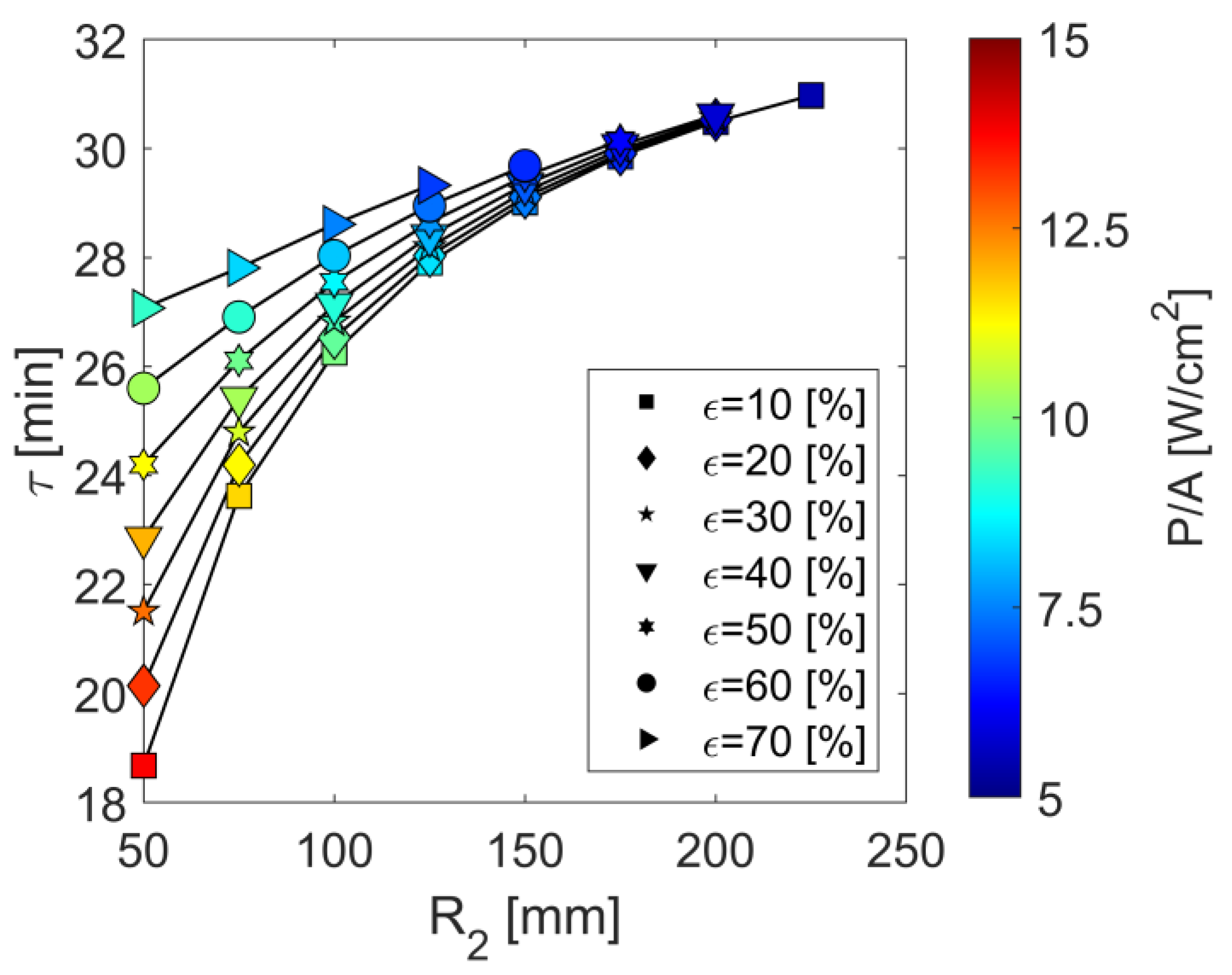
Simulations included variation studies in terms of void fraction (ε) and inner radius (R2). Effects of different specific surfaces (aV) are only marginally present for this operating mode and are, therefore, not presented. For each geometry configuration, the transient heating processes were performed with the maximum heating power of 100 kW specified in Table 1. The simulations were terminated as soon as the heating power dropped below 95 kW due to the implemented heating power control, when the permitted maximum heating temperature (TPtH,max) was exceeded. Results on charging durations (τ) are shown in Figure 2.
The results show that charging durations of up to 31 min are achievable for a given storage mass of 180 kg, whereby these are associated with larger inner radii (R2) and increasing void fractions (ε). The reason for this is increasing heat-absorbing surfaces, which lead, in the annular honeycomb body, to lower heating power densities (P/A) and thus to lower excess temperatures in the areas close to the heating registers. Due to design restrictions considering the limited radial space, higher inner radii are increasingly only achievable with geometry configurations with a lower void fraction of the annular honeycomb body.
Further relevant results regarding the generated and stored electric heat (QS) related to the electric work as well as the achieved maximum temperatures ( T ¯ S ) are summarized in Table 3.
As can be seen, geometric design solutions with achievable charging durations of 30 min are associated with averaged temperature differences inside the inventory body of 803 °C, whereby 85% of the electrically generated heat is stored inside the honeycomb. Up to 5% of the electrical heat is lost to the environment through heat losses, and approximately 10% remains within the thermal insulation.
For the subsequent operating mode—electrical heating via thermal radiation with simultaneous convective flow—variation studies were performed analogously to the relationships explained here. Central results are summarized in Section 4.1.2.

4.1.2. Operating Mode II

At the end of the first operating mode, thus at the end of the start-up procedure of the overall system, an operational change takes place: the component then acts as an electrical heating system, whereby the stored as well as the continuously generated high-temperature heat is convectively transferred to systemic downstream components or to a solid-media TES with high storage capacity, respectively. Within this operating mode, the objective is to identify geometry configurations of the annular ceramic SiC honeycomb that achieve an efficient heat transfer to the heat transfer medium (air) and operating temperatures above 700 °C.
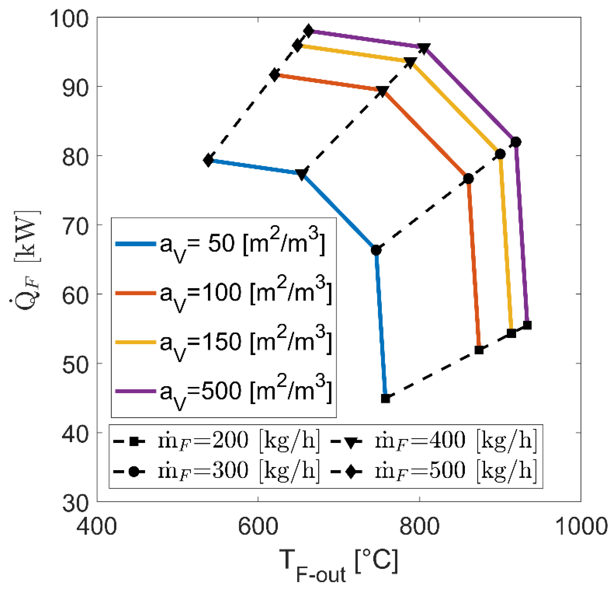
Similarly to Section 4.1.1, simulation studies were performed for the central geometric degrees of freedom—the void fraction (ε), the inner radius (R2) and the specific area (aV). The mass flow rates were varied in the range between 200 and 500 kg/h, and the maximum heating power was set to 100 kW as specified in Table 1. Exemplary results on resulting thermal powers ( Q ˙ F ) and maximum operating fluid outlet temperatures (TF-out) in steady-state condition are shown in Figure 3 based on comparable geometry configurations with respect to void fraction and inner radius.
The mass flow-dependent relationship between specific surface (aV) and achievable thermal power or operating temperature becomes obviously visible. With increasing heat-transferring surfaces, the effectiveness of heat transport improves, whereby excess temperatures at honeycomb body areas close to the heating registers are reduced, allowing finally higher thermal outputs. However, the results also show that above a specific surface of about 150 m2/m3, further improvements cannot be reached. This is due to limitations in thermal conductive heat transfer within the SiC honeycomb, which results in a reduction of the heating power in order not to exceed the defined maximum heating temperature of 950 °C. Despite these limitations, the results show, that steady-state operating temperatures above 800 °C at thermal powers above 90 kW are achievable with the presented concept and suitable geometry configurations.
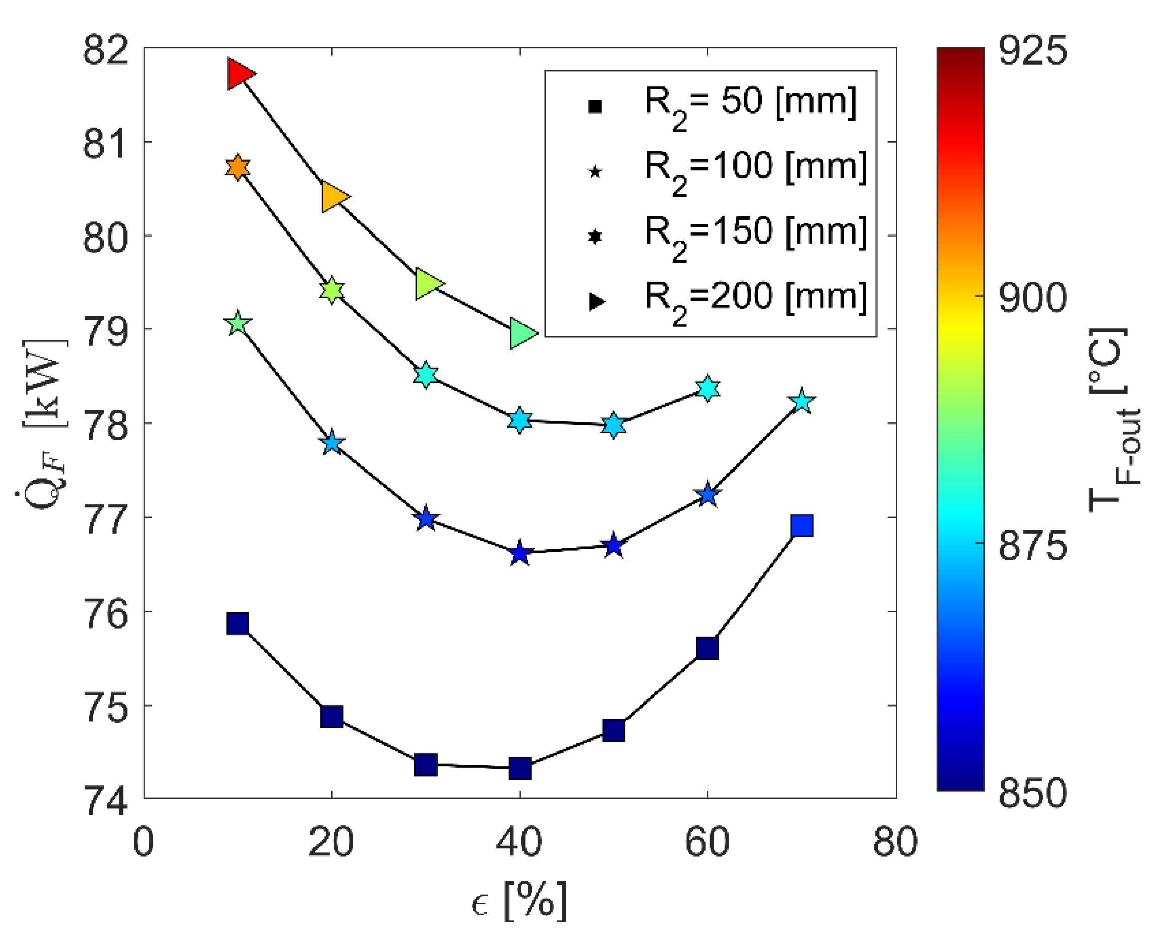
For identification of such design options, the associated geometric relationships between void fraction and inner radius of the annular honeycomb body at an exemplary mass flow rate of 300 kg/h are shown in Figure 4. These characteristics are based on results at a sufficiently high specific surface of 200 m2/m3.
The results for steady-state thermal powers and operating fluid outlet temperatures show a strong dependence on the inner radius and a comparatively moderate one on the void fraction. Analogous to the relationships already explained in Section 4.1.1, increasing inner radii lead to efficiency improvements in the convective operating mode due to increasing heat-absorbing surfaces between the honeycomb and the radiation-based electric heating systems. The void fraction specific minimum, on the other hand, is due to a superposition of the resulting outer diameter of the honeycomb body and the flow velocity with an associated opposite dependence between residence time and heat transfer coefficients. Comparable relationships between inner radius and void fraction to efficiency are also found in the other mass flow rate studies considered. Regardless of pressure loss-specific limitations, design options favored for the convective operating mode are also associated with high inner radii (R2) and low void fractions (ε), with the most significant influence on efficiency by far being the specific surface (Figure 3).

4.1.3. Favorite Geometrical Design Solutions

The identification of favored design options reaching high efficiency in heat transport in both operating modes and high operating temperatures is based on geometry- and mass flow rate-dependent results determined in Section 4.1.1 and Section 4.1.2. For this purpose, requirements were defined for the relevant target variables—operating temperature, charging duration, performance—and design options were selected on the basis of their results. Geometric solutions determined in this way with respect to specific surface, inner radius and void fraction are summarized in Table 4.
The specific surface and the inner radius of the ring-shaped SiC honeycomb show the most significant influence on the efficiency. The void fraction itself plays a subordinate role in comparison, but it is especially important with respect to pressure losses, which were not considered here.
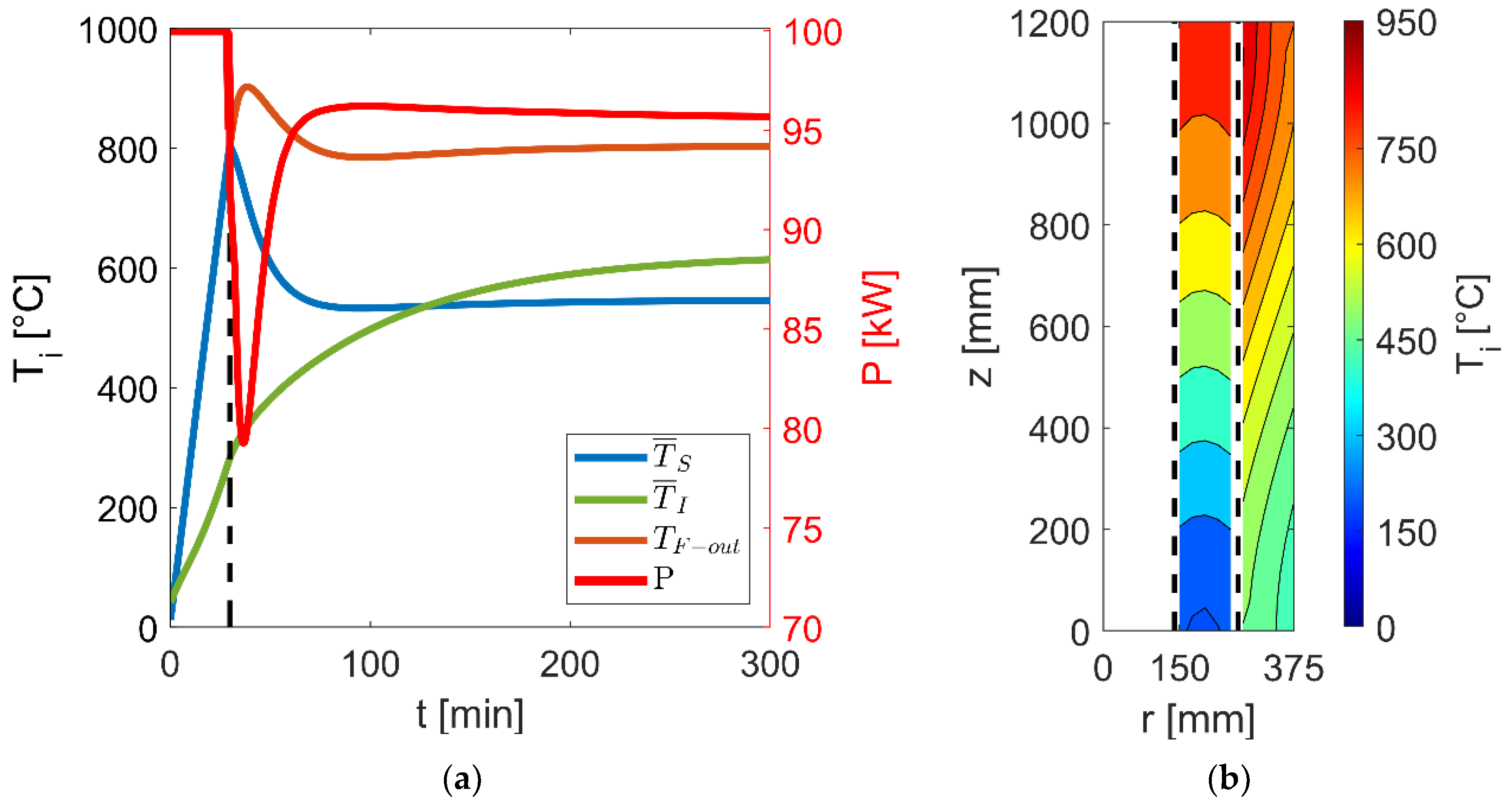
For an exemplary selected geometrical design solution, central results on locally averaged temperatures in both operating modes as well as on stationary local temperature profiles in the convective operating mode are presented in Figure 5.
Within the first operating mode, the results (Figure 5a) show a quasi-linear increase of the averaged storage temperatures ( T ¯ S ) to 800 °C until the electrical heating power (P) falls below the specified 95 kW after about 30 min. From this point on, the operational change from the storage mode to the convective heating mode takes place. Right from this start, high thermal powers are achieved at fluid outlet temperatures (TF-out) of over 800 °C due to the already preheated structures. Due to thermally significantly increased inertias of the thermal insulation ( T ¯ I ), the steady-state condition is reached here only after several hours. These weakly pronounced gradients lead to internal thermal balancing effects between thermal insulation, honeycomb body and heating registers, but are only marginally visible in the fluid outlet temperature with a steady-state level of 805 °C. The local temperature profiles resulting in the steady-state condition (Figure 5b) additionally confirm the homogeneous temperature distribution within the annular honeycomb body caused by the high SiC thermal conductivity. It also points out here that high thermal insulation temperatures occur at the hot-side end, which must be considered in future design studies, especially for upscaled applications in MW scale.

4.2. Experimental Results

For proof of concept and for model validation, a design solution was constructively implemented and integrated within the existing test infrastructure HOTREG [2] of the DLR Stuttgart. Central insights into the test rig of the electrically heated component are presented in Section 4.2.1 and into experimental as well as simulation results in Section 4.2.2.

4.2.1. Experimental Set-Up

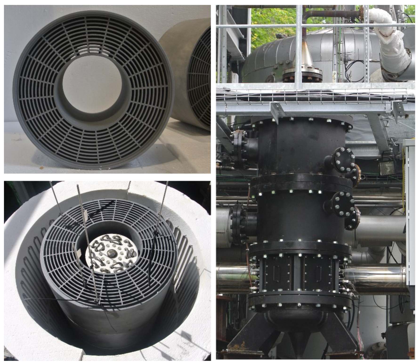
A design option was selected on the basis of the simulated results for testing the electrically heated component with dual operating modes. The geometry solution of this option was integrated in the HOTREG test facility at DLR Stuttgart and experimentally investigated within the Energy Lab 2.0 project. For this purpose, detailed constructive designs were performed with external suppliers for the ring-shaped SiC honeycomb body, the internal and external heating register, and the thermal insulation as well as the space requirements for the metrological instrumentation. Central aspects of the implementation and integration into the test facility are summarized in Figure 6.
The design solution included stacked annular SiC honeycombs with a total length of 1.2 m, a specific surface of 190 m2/m3, a void fraction of 42% with an inner radius of 90 mm and a total mass of 181 kg. The high-temperature heating register placed inside the ring-shaped SiC honeycombs reach a maximum power of 33 kW, and the outer high-temperature heating register integrated on the thermal insulation a maximum power of 66 kW. Both heating registers, each with an effective length of 1.1 m, consist of closely spaced meandering heating wires or rods, enabling a homogeneous heating of the honeycomb bodies with a total output of 100 kW.
The electrically heated component was instrumented metrologically and connected process-technically with the solid-media thermal energy storage system available in the HOTREG test facility in order to achieve holistic investigations of the coupled system within the scope of the Energy Lab 2.0 project. At axial and radial positions, thermocouples (type K and type N) with an accuracy of ±1.5 °C or ±0.4% were integrated within the ring-shaped honeycomb bodies, the thermal insulation and the heating registers as well as at the inlet and outlet, enabling comprehensive temperature measurements for model validation. In addition, the electrical powers per heating register and—during convective operating mode—the specified mass flow rates were recorded, each with a measurement accuracy of 2%. Due to the test rig design, minor adjustments were made to the existing simulation model, mainly involving the length of the heating registers compared to the honeycomb.
Central experimental results and associated model validations are presented in the following. The focus is on measurements of the electrically heated component for both operating modes.

4.2.2. Proof of Concept and Validation

The experimental investigations on the electrically heated storage component focused on measurement campaigns on the operating modes without and with convective flow through the ring-shaped honeycomb bodies. In addition to a successful proof of concept, the overall purpose was to validate the radiation-based simulation model and thus to enable a solid base for future up-scaled design studies.
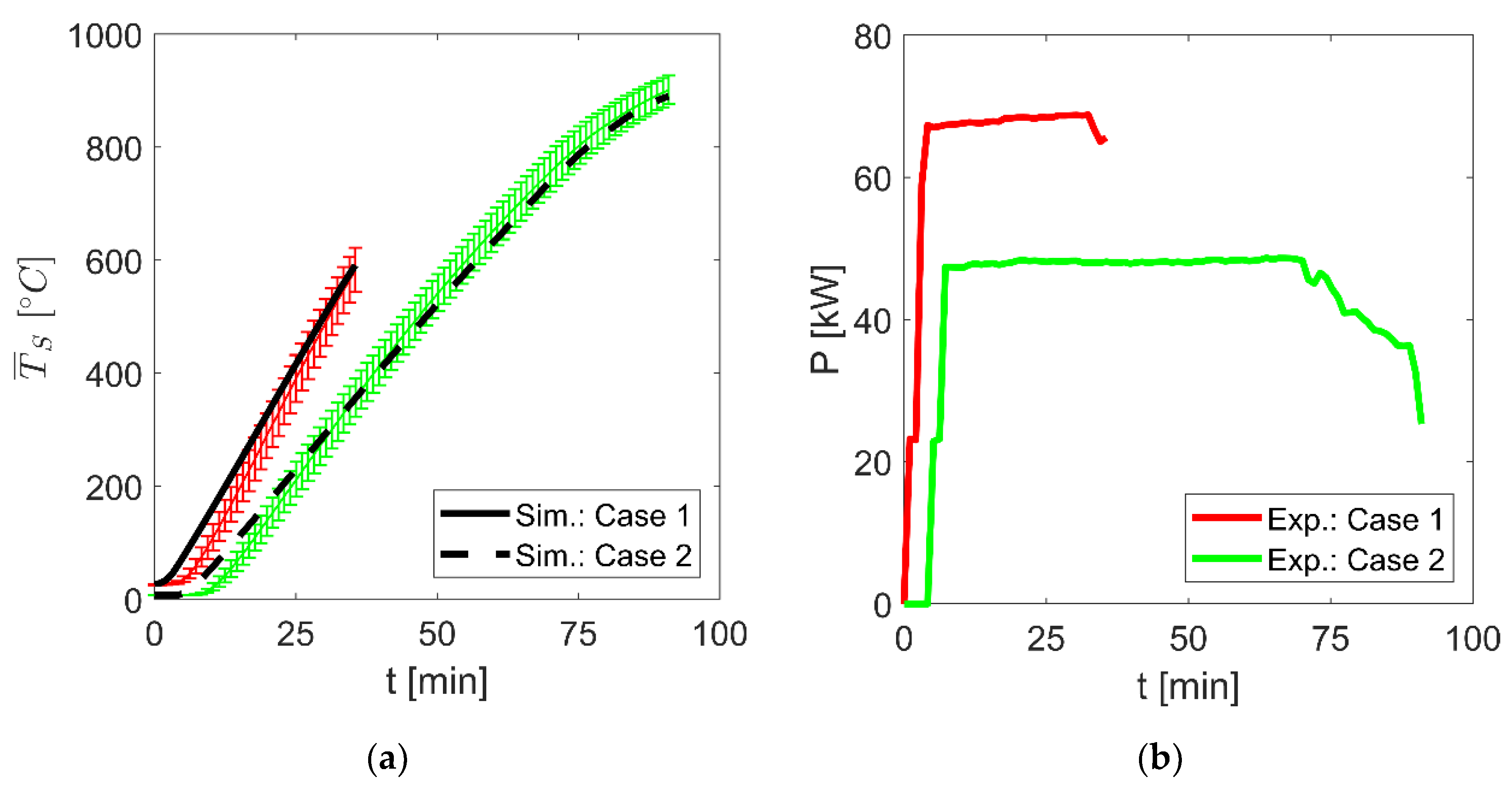
Exemplary results on two measurements for the first operating mode, the storage of electric heat within the electrically heated component, are shown in Figure 7. In the first case (red curve), a maximum total heating power of 66 kW was specified at an averaged inventory temperature ( T ¯ S ) of 600 °C to be reached, and in the second case (green curve), a maximum total heating power of 47 kW at an averaged inventory temperature of 900 °C. The total heating power was divided area-proportionally between the inner (1/3) and outer (2/3) heating registers, and these values were used as input variables in the simulation model. The maximum permitted heating temperatures (TPtH,max) were specified as 1000 °C.
The results in Figure 7a show good agreement between the experimental and simulated temperature characteristics during the transient heating process for both measurements. Despite the radial heating input, comparatively homogeneous temperatures of the honeycomb body were achieved due to the high SiC thermal conductivity. Figure 7b also clearly shows the drop in electrical heating power over the time of the measurements. The reason for this is the power control, implemented both in the experiments and in the model, which leads to a reduction in the heating power when the maximum permitted heating temperature is reached. The high storage temperatures of more than 800 °C, targeted for this operating mode, with simultaneously constant heating power were successfully achieved at heating temperatures of 1000 °C.
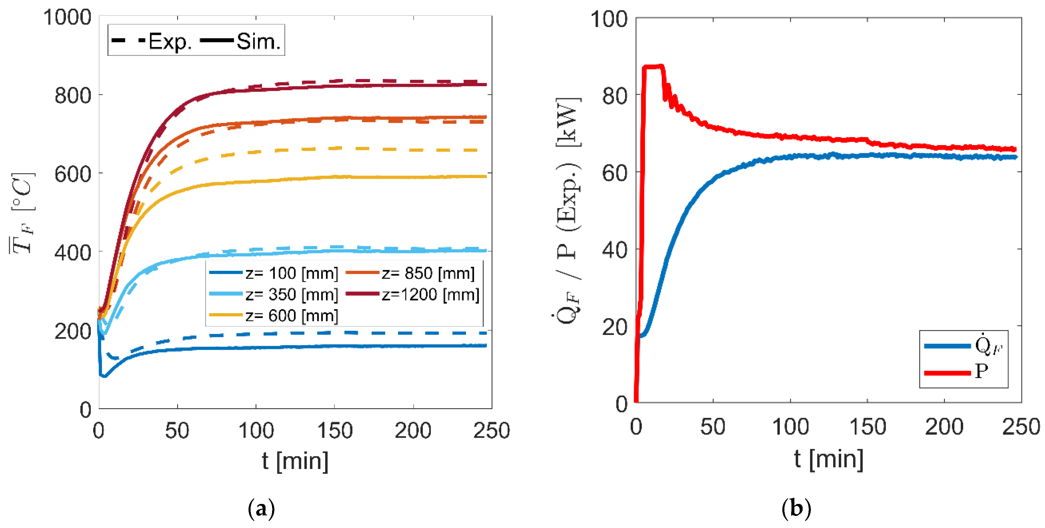
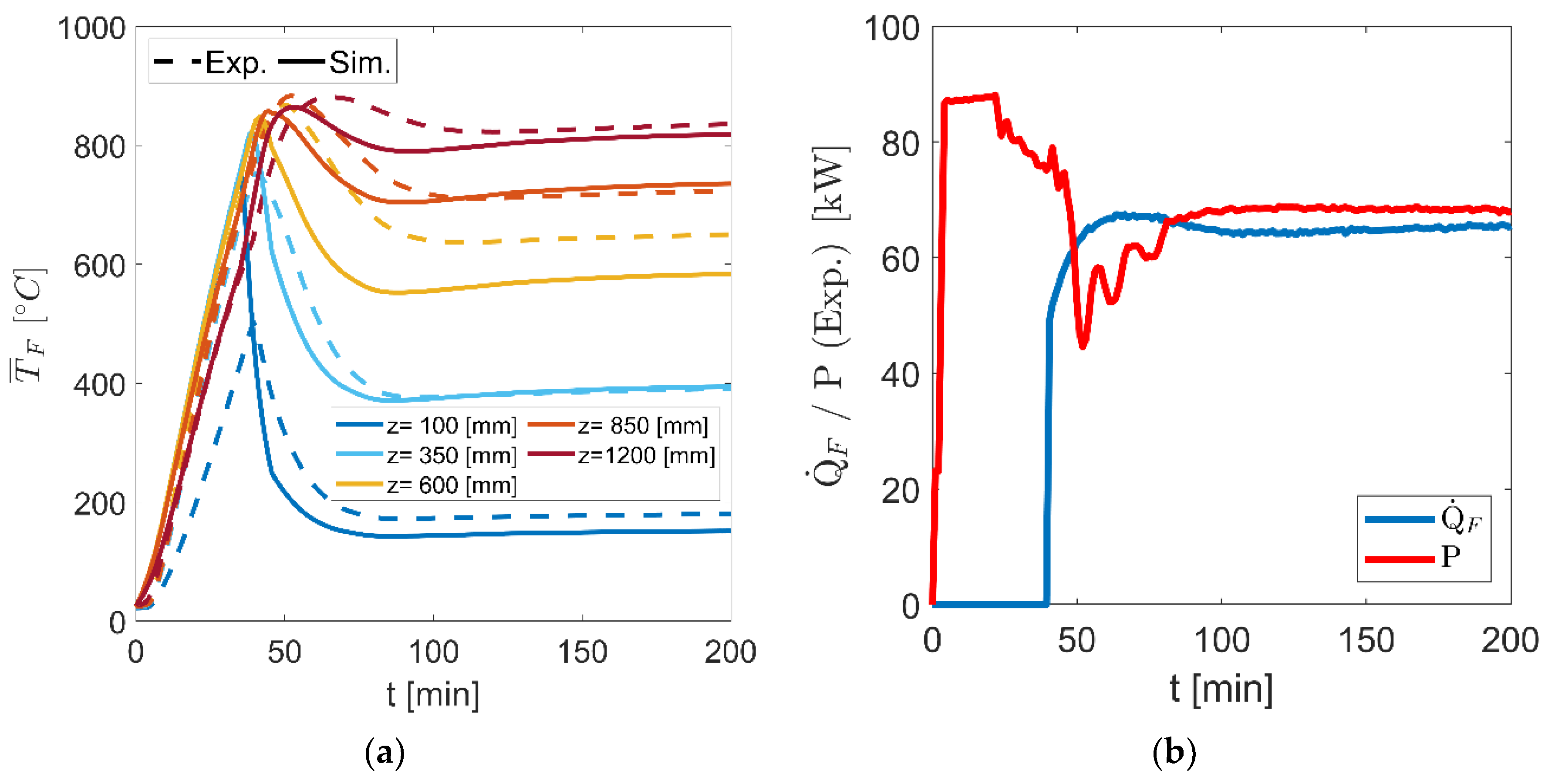
To investigate the developed component in the second operating mode, electrical heating with simultaneous convective flow, variation studies on heating powers as well as on mass flow rates were performed and compared with simulation results. Exemplary results for radially averaged fluid temperatures ( T ¯ F ) within the honeycomb body as well as for the temporal characteristics of the heating power are shown in Figure 8. In the measurement selected here, a maximum total heating power of 90 kW and a mass flow rate of 260 kg/h were specified. The total heating power was divided area-proportionally between the inner (1/3) and outer (2/3) heating registers and the maximum permitted heating temperature (TPtH,max) was set to 1000 °C.
In addition to good agreement between simulation and measurement results, it is visible from Figure 8a that the cold entering air is successively heated across the flow path and reaches maximum temperatures of 830 °C at the outlet of the developed electrically heated storage component. The highest deviations are found at z = 600 mm and are mainly caused by the temperature-averaged material properties for the fluid and solid phase within the simulation results.
The radial temperature distributions due to the two-sided radially radiated heating showed deviations of less than 20% related to the averaged temperatures at each axial position in the experimental and less than 13% in the simulations results. The comparable low deviations were caused by the high thermal conductivity of the SiC-based ceramic, but were underestimated inside the simulation model. Model extensions regarding effective thermal conductivities in the radial direction for porous structures are needed to improve the simulations’ quality, especially for large-scaled designs.
With respect to Figure 8b, at the beginning, the maximum specified heating power of 90 kW was achieved, which was reduced to 66 kW in steady-state condition. The reason for this was the implemented power control, which—after ending transient processes—led to a reduction of the heating power in order to maintain the permitted maximum heating temperature. The thermal power itself showed temporally increasing values due to initial thermal inertias, whereby at steady-state condition, 64 kWth was reached, resulting in only marginal heat losses of less than 3% related to the electric power. Analogously, variation studies were performed on steady-state heating powers and mass flow rates, showing comparable characteristics and good agreements between the transient experimental and simulation results.
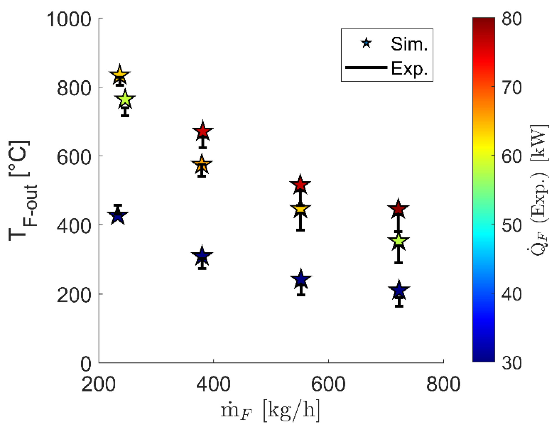
To evaluate the performance of the electrically heated storage component in the second operating mode over the whole range, steady-state results are presented in Figure 9.
The steady-state characteristics illustrate the well-known relationship between outlet temperature, mass flow rate and heating power as well as the good agreement between experimental and simulation results. At high outlet temperatures or at high thermal powers, the power control described above leads to a limitation of the electrical heating power, which results in restrictions to the maximum permitted heating power in the steady-state condition of approximately 24% at TF-out = 700 °C and of 35% at TF-out = 830 °C. Optimizations with respect to honeycomb geometry and heating register arrangement as described in Section 4.1 as well as to operating heating temperatures by means of ceramic heating elements [24,25] allowed further increases in performance with a significant reduction of limitation on heating power. Additionally, as visible with increasing mass flow rates, the experimental results showed higher deviations. This is due the fact of increasing flow maldistributions at the inlet and between the staked honeycomb bodies, leading radially and axially to higher volatilities in convective heat transport.
For the final evaluation of the electrically heated storage component, the transient characteristics were investigated for both operating modes running directly one after the other. Exemplary results at a maximum total heating power of 90 kW and a mass flow rate of 260 kg/h are shown in Figure 10. Analogously with previous results, the total heating power was divided area-proportionally between the inner (1/3) and outer (2/3) heating registers and the maximum permitted heating temperature (TPtH,max) was set to 1000 °C.
Despite test rig-specific limitations, the results here also confirm the high performance of the developed component in achieving both high operating temperatures of over 800 °C and simultaneously enabling dual operation functionality. During the first operating mode with pure radiative heating, a comparably homogeneous temperature elevation was observed in the simulation and experimental results. Significant deviations were visible only at the lowest part at z = 100 mm due to locally test rig-related high specific heat losses. Similarly to previous explanations, the maximal radial temperature deviations were reached during the second operating mode, whereby less than 19% related to each axial position was determined in experimental and less than 11% in simulation results.
With special regard to the operating modes running directly one after the other and despite further needed control optimization, the overall purpose of the novel concept and developed component becomes visible: fast integration of electrical energy from the beginning at high values without systemic limitations (operating mode I) and—after reaching the fully thermally charged storage—instantaneously high thermal powers (operating mode II), for instance, for thermally charging cost-efficient, large-scaled solid medium thermal energy storage. Compared to today’s solutions with an external storage device and convection-based heating elements [16,17,18,19,20,21] limited to 700 °C for MW-scaled applications, significant benefits in system dynamics with simultaneously high operational temperatures of over 800 °C are reached through the new concept.
For future design studies, especially under large-scale scenarios, further investigations are needed. Special attention should be paid to the following:
-
identification of the maximal size of the internal, radiative heated storage system with dual operating modes in combination with an external cost-effective solid-media thermal energy storage system
-
design optimizations to improve the maximum operational temperature via ceramic heating elements with radial orientation
-
lifetime predictions based on FEM models for the brittle SiC material
With these results, the limitations of the proposed system in terms of size, temperature and dynamics were derived, and well-founded systemic case studies for suitable applications in terms of techno-economical optimizations can be conducted. Regardless of these open questions, the developed, tested and validated internal electrically heated storage component, as part of the Energy Lab 2.0 project, confirms even now with its results the overall benefits: improved system dynamics due to the operational flexibility, cost reduction potential due to high operating temperatures, and finally, economic advantages for future large-scaled power-to-heat-to-power systems, in particular through coupling with a solid-media thermal energy storage system with high storage capacity.

5. Conclusions

The research infrastructure erected as part of the nationally funded Energy Lab 2.0 project enables the testing of new technologies and approaches for the generation, conversion and storage of various energy sources and their interconnection. In addition to specific technology developments, the infrastructure allows investigations on energy services of decentralized energy plants, on improvements of flexibilities and on new approaches to stabilize the energy networks. One element within this network is a thermal energy storage system with high storage capacity based on solids, which was extended by an electrically heated storage component with a maximum heating power of 100 kW. In this context, the coupled energy storage systems act as a dynamic and flexible subsystem that can store electrically generated heat efficiently with high operating temperatures of over 800 °C and provide it during times of thermal energy demand.
For this purpose, an electrically heated storage component with dual operating modes was developed for the first time, enabling high load gradients in the integration of electrical energy at a superordinate systemic level, leading to a significant reduction in systemic inertias. This was achieved by using electrical energy directly for internally heating a storage inventory via thermal radiation—detached from systemic start-up procedure—while the superordinate overall system is brought to its nominal operating state with lower load gradients. At the end of systemic start-up procedures, an operational change takes place: the electrically heated storage component then acts analogously to current approaches as an electrical heating system, transporting the stored as well as continuously generated high-temperature heat to downstream components or to a large-scaled solid-media thermal energy storage system with high capacity.
To identify such a component with dual operating modes and specifically for high-temperature requirements, a favored design solution with high electrothermal efficiency of more than 90% for both operating modes and operating temperatures of more than 800 °C was developed via detailed models and wide simulation studies. For proof of concept, a design solution was constructively implemented and tested through experimental investigations at 100 kW scale. The validated and novel concept consists of an annular SiC honeycomb body, which is radially heated by an inner and outer high-temperature heating register. Due to the high heat transfer efficiency in both operating modes and despite test rig-related limitations, high operating temperatures of 830 °C have already been achieved at steady-state heating powers of up to 65 kW. Further technological improvements in performance can be reached by optimizing the honeycomb geometry, heating register arrangement and heating temperature using ceramic heating elements.
The use of this developed technology, especially in combination with a solid-media thermal energy storage system with high storage capacity, is particularly suitable for two future applications: power-to-heat-to-power storage power plants and electrification of fossil-fueled industrial processes. In the first, the electrically heated high-temperature storage system with dual operating modes will achieve a significant increase in dynamics and cost efficiency through systemically improved start-up procedures and higher operating temperatures, and in the second, a fuel reduction of natural gas-fired processes through alternative heat supply above 800 °C. Further developments will, therefore, focus on design studies for up-scaled solutions in the MW range, holistic optimizations to the storage capacity between the developed electrically heated storage component and the high-temperature solid-media heat storage system, and their dynamic interactions.

Author Contributions

Conceptualization, V.D.; methodology, V.D.; validation, G.L.; investigation, V.D.; writing—original draft, V.D.; visualization, V.D. All authors have read and agreed to the published version of the manuscript.

Funding

This project received funding from the German Federal Ministry for Economic Affairs and Climate Action (BMWK) under grant agreement No. 03ET6115.

Data Availability Statement

Not applicable.

Conflicts of Interest

The authors declare no conflict of interest. The funders had no role in the design of the study; in the collection, analyses, or interpretation of data; in the writing of the manuscript; or in the decision to publish the results.

References

  1. Available online: https://www.elab2.kit.edu/english/index.php (accessed on 7 September 2023).
  2. Available online: https://www.dlr.de/en/research-and-transfer/research-infrastructure/hotreg-en (accessed on 7 September 2023).
  3. Krüger, M.; Haunstetter, J.; Zunft, S. Slag as an inventory material for heat storage in a concentrated solar tower power plant: Experimental studies on design and performance of the thermal energy storage. In Proceedings of the International Renewable Energy Storage Conference (IRES), Düsseldorf, Germany, 12–14 March 2019. [Google Scholar]
  4. Dehghan, M.; Ghasemizadeh, M.; Rashidi, S.; Pourrajabian, A.; Rahgozar, S.; Arabkoohsar, A. Sensible thermal energy storage. In Future Grid-Scale Energy Storage Solutions; Elsevier: Amsterdam, The Netherlands, 2023. [Google Scholar] [CrossRef]
  5. Beckmann, G.; Viktor, P. Thermal Energy Storage; Springer: New York, NY, USA, 1984. [Google Scholar]
  6. Krüger, M.; Muslubas, S.; Loeper, T.; Klasing, F.; Knödler, P.; Mielke, C. Potentials of Thermal Energy Storage Integrated into Steam Power Plants. Energies 2020, 13, 2226. [Google Scholar] [CrossRef]
  7. Holy, F.; Textor, M.; Lechner, S. Gas turbine cogeneration concepts for the pressureless discharge of high temperature thermal energy storage units. J. Energy Storage 2021, 44, 103283. [Google Scholar] [CrossRef]
  8. Alami, K.E.; Asbik, M.; Agalit, H. Identification of natural rocks as storage materials in thermal energy storage (TES) system of concentrated solar power (CSP) plants—A review. Sol. Energy Mater. Sol. Cells 2020, 217, 110599. [Google Scholar] [CrossRef]
  9. Trevisan, S.; Guédez, R.; Laumert, B. Thermo-economic optimization of an air driven supercritical CO2 Brayton power cycle for concentrating solar power plant with packed bed thermal energy storage. Sol. Energy 2020, 211, 1373–1391. [Google Scholar] [CrossRef]
  10. Pradepp, N.; Reddy, K.S. Design and investigation of solar cogeneration system with packed bed thermal energy storage for ceramic industry. Renew. Energy 2022, 192, 243–263. [Google Scholar] [CrossRef]
  11. Seyitini, L.; Belgasim, B.; Enweremadu, C.C. Solid state sensible heat storage technology for industrial applications—A review. J. Energy Storage 2023, 62, 106919. [Google Scholar] [CrossRef]
  12. Budt, M.; Wolf, D.; Span, R.; Yan, J. A review on compressed air energy storage: Basic principles, past milestones and recent developments. Appl. Energy 2016, 170, 250–268. [Google Scholar] [CrossRef]
  13. Zunft, S.; Dreissigacker, V.; Bieber, M.; Banach, A.; Klabunde, C.; Warweg, O. Electricity storage with adiabatic compressed air energy storage: Results of the BMWi-project ADELE-ING. In Proceedings of the International ETG Congress 2017, Bonn, Germany, 28–29 November 2017; pp. 1–5. [Google Scholar]
  14. Steinmann, W.-D.; Bauer, D.; Jockenhöfer, H.; Johnson, M. Pumped thermal energy storage (PTES) as smart sector-coupling technology for heat and electricity. Energy 2019, 183, 185–190. [Google Scholar] [CrossRef]
  15. Paul, A.; Holy, F.; Textor, M.; Lechner, S. High temperature sensible thermal energy storage as a crucial element of Carnot Batteries: Overall classification and technical review based on parameters and key figures. J. Energy Storage 2022, 56, 106015. [Google Scholar] [CrossRef]
  16. Trieb, F.; Liu, P.; Koll, G. Thermal Storage Power Plants (TSPP)—Operation modes for flexible renewable power supply. J. Energy Storage 2022, 50, 104282. [Google Scholar] [CrossRef]
  17. Dreißigacker, V.; Belik, S. System configurations and operational concepts for high efficient utilization of Power-to-Heat in A-CAES. Appl. Sci. 2019, 9, 1317. [Google Scholar] [CrossRef]
  18. Belik, S. Power-to-heat integration in a two-stage brayton battery configuration: Increasing system cost efficiency and flexibility. In Proceedings of the 3rd International Workshop on Carnot Batteries, Stuttgart, Germany, 27–28 September 2022. [Google Scholar]
  19. Sergio, L. Fundamentals of electroheat. In Electrical Technologies for Process Heating; Springer: Cham, Switzerland, 2017. [Google Scholar]
  20. Ohmex. Electrical Process Flow Heaters Datasheet. 2021. Available online: https://www.ohmex.de/en/wp-content/uploads/sites/3/2020/03/electric-process-heater_STR_2020-03.pdf (accessed on 25 April 2022).
  21. Schniewindt. Flow Heaters. 2021. Available online: https://www.schniewindt.de/en/csn-flow-heaters (accessed on 25 April 2022).
  22. Belik, S.; Khater, O.; Zunft, S. Induction Heating of a Fluidized Pebble Bed: Numerical and Experimental Analysis. Appl. Sci. 2023, 13, 2311. [Google Scholar] [CrossRef]
  23. Belik, S.; Dreissigacker, V.; Zunft, S. Power-to-heat integration in regenerator storage: Enhancing thermal storage capacity and performance. J. Energy Storage 2022, 50, 104570. [Google Scholar] [CrossRef]
  24. He, R.; Tong, Z.; Zhang, K.; Fang, D. Mechanical and electrical properties of MoSi2-based ceramics with various ZrB2-20vol% SiC as additives for ultra high temperature heating element. Ceram. Int. 2018, 44, 1041–1045. [Google Scholar] [CrossRef]
  25. Available online: https://berghuetten-gmbh.de/en/products/heizstabe-aus-silizium-karbid (accessed on 7 September 2023).
  26. Carslaw, H.S.; Jaeger, J.C. Conduction of Heat in Solids; Clarendon Press: Oxford, UK, 1967. [Google Scholar]
  27. Ismail, K.A.R.; Stuginsky, R. A parametric study on possible fixed bed models for pcm and sensible heat storage. Appl. Therm. Eng. 1999, 19, 757–788. [Google Scholar] [CrossRef]
  28. Schmidt, F.W.; Willmott, A.J. Thermal Energy Storage and Regeneration; McGraw-Hill Book Company: New York, NY, USA, 1981. [Google Scholar]
  29. Kakaç, S.; Shah, R.K.; Aung, W. Handbook of Single-Phase Convective Heat Transfer; Wiley: New York, NY, USA, 1987. [Google Scholar]
  30. Fujii, T.; Uehara, H. Laminar natural-convective heat transfer from the outer surface of a vertical cylinder. Int. J. Heat Mass Transf. 1970, 13, 607–615. [Google Scholar] [CrossRef]
  31. Howell, J.; Siegel, R.; Mengüç, M.P. Thermal Radiation Heat Transfer; CRC Press: Boca Raton, FL, USA, 2010. [Google Scholar] [CrossRef]
  32. Silca Refractory Solutions. Thermal Insulation, Non-Ferrous Meatal Casting & Fire Protection Catalogue 2018. Available online: https://www.silca-online.de/fileadmin/2.pdf/04.produktdatenblaetter-ht-en/PDB-SILCAFELT_EN.pdf (accessed on 15 July 2022).
  33. BCE Special Ceramics. Comparison Table for Technical Ceramics. 2021. Available online: https://www.bce-special-ceramics.com/comparison/bce-material-table.htm (accessed on 15 July 2022).
  34. Lemmon, E.W.; Jacobsen, R.T.; Penoncello, S.G.; Friend, D.G. Thermodynamic properties of air and mixtures of nitrogen, argon and oxygen from 60 to 2000 K at Pressures to 2000 Mpa. J. Phys. Chem. Ref. Data 2000, 29, 331–385. [Google Scholar] [CrossRef]
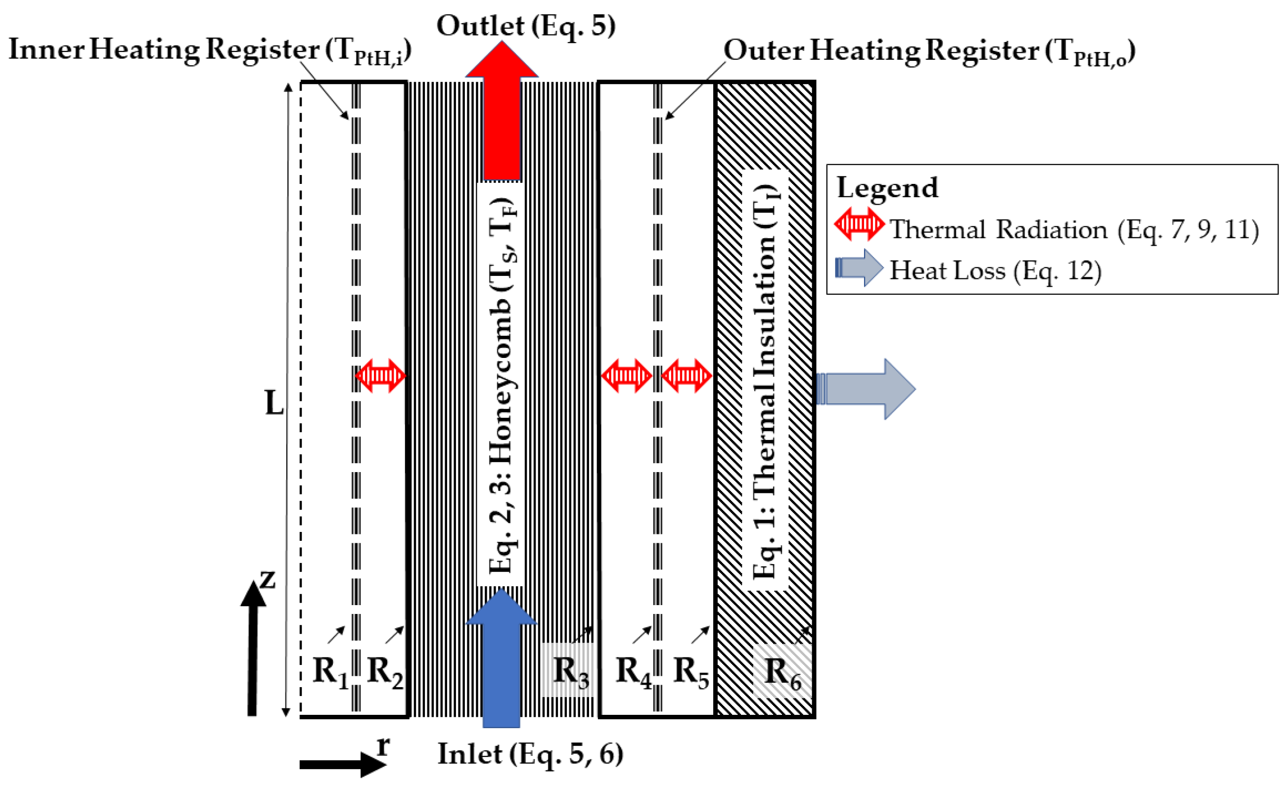
Figure 1. Electrically heated storage component with dual operating modes.
Energies 16 07344 g001
Figure 2. Charging duration (τ) and heating power densities (P/A) as a function of the inner radius (R2) and void fraction (ε) of the annular honeycomb body.
Energies 16 07344 g002
Figure 3. Steady-state thermal powers ( Q ˙ F ) and fluid outlet temperatures (TF-out) as a function of mass flow rate ( m ˙ F ) and specific surface (aV) of the annular honeycomb body.
Energies 16 07344 g003
Figure 4. Steady-state thermal powers ( Q ˙ F ) and fluid outlet temperatures (TF-out) as a function of the inner radius (R2) and void fraction (ε) of the annular honeycomb body.
Energies 16 07344 g004
Figure 5. Transient characteristics (a) and steady-state temperature profiles (b) of a favored design solution with a specific surface of 300 m2/m3, an inner radius of 150 mm and a void fraction of 60% at a mass flow rate of 400 kg/h.
Energies 16 07344 g005
Figure 6. Annular honeycomb body (top left), heating registers with honeycomb body and thermal insulation (bottom left), electrically heated storage component (in the foreground) with integration to the solid-media thermal energy storage (right).
Energies 16 07344 g006
Figure 7. Transient heating processes in the first operating mode; (a): averaged inventory temperatures ( T ¯ S )—(b): temporal characteristics of heating powers (P).
Energies 16 07344 g007
Figure 8. Local radially averaged fluid temperatures ( T ¯ F ) within the annular honeycomb bodies (a) and temporal characteristics of the thermal ( Q ˙ F ) and electrical powers (P) (b).
Energies 16 07344 g008
Figure 9. Steady-state fluid outlet temperatures (TF-out) and thermal powers ( Q ˙ F ) as a function of mass flow rates ( m ˙ F ).
Energies 16 07344 g009
Figure 10. Local radially averaged fluid temperatures ( T ¯ F ) within the annular honeycomb bodies (a) and temporal characteristics of the thermal ( Q ˙ F ) and electrical powers (P) (b) over both operating modes.
Energies 16 07344 g010
Table 1. HOTREG test infrastructure specifications.
Operating ParametersValues
maximum electric power (P)100 kW
mass flow rate ( m ˙ F )200–720 kg/h
pressure (p)1 bar
heat transfer mediumAir
Table 2. Electrically heated component specifications.
SpecificationsValues
mass of the annular honeycomb (mS)180 kg
length of the annular honeycomb (L)1.2 m
maximum radius (R6)0.375 m
insulation thickness (R6R5)0.1 m
maximum permitted heating temperature (TPtH,max)950 °C
Table 3. Stored heat (QS) and maximum temperature difference ( T ¯ S ) as a function of charging duration (τ).
τ [min]QS/(P τ) [%] T ¯ S [°C]
2083520
2584662
3085803
Table 4. Favored geometric design solutions with operating temperatures above 800 °C, charging durations above 27.5 min (τ/τmax > 90%), steady-state thermal powers above 90 kW ( Q ˙ F /P > 90%).
aV [m2/m3]R2 [mm]ε [%]
≥200≥15010–60
Disclaimer/Publisher’s Note: The statements, opinions and data contained in all publications are solely those of the individual author(s) and contributor(s) and not of MDPI and/or the editor(s). MDPI and/or the editor(s) disclaim responsibility for any injury to people or property resulting from any ideas, methods, instructions or products referred to in the content.