1. Introduction
The Kingdom of Saudi Arabia (KSA) has a diversified climate varying from extreme hot in summer to extreme cold in winter. KSA has recorded a 3 °C increase in its average summer temperature in many areas over the past 40 years [
1]. The seasonal variability in KSA is classified as winter (December, January, and February), spring (March, April, and May), summer (June, July, and August), and autumn (September, October, and November) [
2]. The average temperature in KSA during summer is 2.5 times the average temperature in winter. The highest temperature recorded in KSA is 53 °C in the last 45 years [
3]. Preliminary data shows that warming in the city of Riyadh for summer and winter have trends of 0.058 °C and 0.042 °C per year, respectively [
4]. KSA is estimated to experience a temperature increase of 6 °C for the summer month by 2081–2100 compared to 1986–2005 [
5]. The hottest month in Riyadh is July with daily maximum and minimum temperatures of 43 °C and 30 °C, respectively [
6]. Every 1 °C rise in the earth’s atmospheric temperature is estimated to increase the electricity demand for air conditioning by up to 15%, which is much higher in developing countries, contributing to high income and standard of living [
7]. Almost 73% of the total population in KSA is estimated to use AC for 10 and 24 h a day during the summer season [
8]. Energy consumption is projected to rise around 15% in 2030 and 39% in 2050 with an average annual rate of approximately 2% [
9]. The use of fossil fuels for energy consumption is detrimental to nature in distorting the ecological balance of the climate via the emission of greenhouse gases (GHG).
Electricity consumption in buildings increased enormously during the years 1990–2019 from 104,252 to 462,614 TJ, which is 43–60% of the total electricity produced [
10]. A study shows that 66% of the energy produced in KSA is consumed for building cooling [
11]. It is estimated that 63% of the total greenhouse gas emissions are caused by the production of the energy required to drive refrigeration and air-conditioning systems [
12]. One of the most promising air-conditioning alternatives to the conventional vapor compression system (VCR) is the vapor absorption refrigeration (VAR) system [
13]. The VAR system has remained favorable due to the use of renewable energy sources and low-grade waste heat for its operation and use of water as refrigerant [
14]. The multiple-effect absorption system requires a high temperature of around 180–210 °C as compared to the single-effect one, which can perform at 80 °C [
15]. Solar air cooling and heating cost 60–120% higher than conventional systems but it reduces fossil-fuel-based energy consumption by 45–75% and carbon dioxide emission by 40–70% [
16]. The number of solar cooling plants is increasing every year; on top of the 1200 presently in operation, 1200 more are ready to be built all over the world [
17]. Solar absorption chiller systems can lower energy consumption by up to 48% of primary consumption and 17% of CO
2 emission compared to the compression system [
18]. Solar energy from solar photovoltaic (PV) panels using passive cooling enhances the power output from the PV system [
19]. Compound parabolic collectors (CPCs) are capable of delivering all the solar radiations falling within their aperture and they limit the requirements for moving the collector to capture the solar radiations [
16]. Hence, they are a good alternative to parabolic dish or evacuated tube collectors which incur higher cost.
Refrigeration systems use condensers to release the heat extracted from the cooling space to the outside environment [
20]. One of the most common methods to enhance the performance of refrigeration systems includes efficient heat dissipation through condensers. Insufficient dissipation of heat from the condenser increases the pressure and power consumption of the cooling system and decreases the efficiency of the system [
21]. Condenser temperatures of all refrigeration and air-conditioning machines are controlled by ambient temperature in all locations. Ambient temperature controls the cooling effect produced as well as the overall coefficient of performance of both room air conditioners as well as automobile air conditioners, which is a consequence of the second law of thermodynamics [
22]. The most common types of coolant used for condensers are air and cooling water. Generally, the cooling methods implemented for dissipating the condenser heat include high air volume flow rate, evaporative cooling, and water cooling [
23]. The selection of a condenser is essential for the effective performance of a refrigerant system and is one of the vital components of the system [
24]. Tests were conducted by pre-cooling the ambient air by 4 °C before its entrance into the condenser, which was found to enhance cooling capacity by up to 30% and decrease the power consumption by about 6.1% [
25]. Studies show that a 1 °C increase in the ambient temperature decreases the cooling rate and COP of the air-conditioning system by 2% [
26]. Cooling the condenser of split air conditioning using the evaporative cooling technology in ambient temperature (35–57 °C) resulted in a 17.14% and 109% increase in COP, respectively, and a saving of energy of 20.67% and 46.63%, respectively, compared with original ambient temperature conditions of 40–57 °C [
27]. Several researchers have found the effectiveness of condenser cooling, with energy savings of 5% and 7.3% for March and April, respectively [
28]. Using a spray evaporative cooler to cool the condenser of an air-cooled chiller resulted in an improvement of COP from 4% to 8% and electricity saving up to 13.5% [
29]. In a study conducted on cooling performance using evaporative cooling, COP was increased by 10.2% to 35.3% and the cooling capacity by 5.8% to 18.6%, and power consumption decreased 4% to 12.4% [
30]. In a study, the use of the evaporative cooling method instead of air cooling resulted in an increase in COP of up to 58% and a decrease in power consumption of 113% for cooling capacity of 3.3 MW [
31]. One of the recent advances reported in the area of condenser performance enhancement is the application of devices that reduce the temperature of the air entering the outdoor units (ODUs) of split air conditioners [
32]. This was done by using evaporative cooling pads which have water-laden pads that produce a cooling effect on the air entering the condenser.
The temperature of the condenser in the solar VAR system is a critical variable that determines its coefficient of performance. The performance of the refrigeration systems is strongly determined by the heat transfer to the environment through a condenser; reducing the temperature difference between the condensers by up to 1 °C provides 34% energy saving [
33]. A significant decrease in the COP and efficiency ratio was recorded with an increase in the condenser and absorber temperature at a generator temperature of 80 °C using a water-cooled condenser for the VAR system; with an increase of 1 °C in the cooling water temperature, the efficiency increases by 2.3% [
34]. Vapor absorption refrigeration systems working with solar energy as the heat source have a low coefficient of performance due to the high ambient conditions that determine condenser temperature as well as water shortages which prevent usage of water-cooled condensers. The effect of using evaporative-cooled air on condenser performance of a 1 TR air conditioner was studied and the required conditions for obtaining air at minimum temperatures were analyzed [
35]. The performance of a solar absorption air-conditioning system under arid conditions was analyzed and an adverse impact on performance during hot conditions was indicated [
36]. The above studies reveal that SVAR cooling machines can be used as an alternative to conventional cooling techniques. The above literature studies give the conclusive fact that performance of the SVAR system is dependent on the heat input into the generator as well as heat removal in a condenser. The CPC as a solar collector can eliminate the problem of low generator temperature and enhance the overall performance of the SVAR. The temperature and pressure at the condenser can effectively contribute to the COP of the system by incorporating an efficient condenser cooling technique for removing the process heat. This study is focused on identifying the appropriate condenser cooling mechanism that will help to improve the cooling performance of the SVAR systems. Four different alternate condenser cooling mechanisms are analyzed in this study. Their effect on the overall system performance is evaluated using EES. The results of the performance are analyzed on a seasonal basis and the annual best performance alternative is suggested.
2. Materials and Methods
A typical SVAR system is a thermally powered cooling system that utilizes heat from solar radiation to provide cooling. The five main components of the solar vapor absorption cooling system are the solar collector, generator, condenser, evaporator, and absorber. The VAR system was divided into two pressure levels, high and low, by a pump and two expansion valves. A heat exchanger between the generator and absorber is used to increase system performance.
Figure 1 displays a schematic diagram of the SVAR system. The circulating fluid (LiBr/water) is initially heated by the solar CPC collector using energy from the sun. In the generator, the heat gained from the solar CPC collector is used to separate the water vapor and lithium bromide from the solution at states 1 and 8, respectively. The water vapor then continues to flow through the condenser, liberating heat to produce liquid water at state 2. The high-pressure liquid water at state 2 is routed through the expansion valve at state 3 to the evaporator, where it evaporates at low pressure, providing cooling to the space that needs to be cooled. The water vapor at state 4 is transferred from the evaporator to the absorber. Meanwhile, at state 8 the strong solution from the generator passes through a heat exchanger to preheat the weak solution entering the generator before being expanded in the absorber at state 10. The strong lithium bromide solution in the absorber absorbs the water vapor that comes from the evaporator, producing a weak solution at state 5. The weak solution is pumped into the generator at state 6, which then passes through a heat exchanger to preheat before entering the generator at state 7 and the cycle is repeated [
37]. A condenser cooling system (air, water, or evaporative) removes heat from the system. The cooling circulation fluid circulates through the absorber and condenser, discharging heat into the environment.
This study applies a low-capacity 3 TR, single-stage LiBr/water VAR system that is appropriate for cooling small residential buildings. EES was used to simulate and determine the system performance. The thermodynamic properties of LiBr/water from the EES library were used to estimate the state equations. A solar CPC collector was integrated to produce the thermal energy needed for the VAR. Simulation results on the performance of the solar vapor absorption refrigeration (SVAR) system using different cooling methods (air, water, evaporative, and hybrid) are presented for the 21st day of four distinct months (January, April, July, and October) of the year, corresponding to four different seasons for Riyadh, KSA.
The development of the mathematical model depends upon analyzing, studying, and evaluating the performance of the SVAR system. The developed model demonstrates the effect of condenser cooling using different methods on the overall performance of the SVAR system. The thermodynamics properties, parameters, variables, and mathematical relationships will be formulated to determine the COP through mass- and heat-transfer balance. The four condenser cooling methods considered are air cooling, water cooling, evaporative cooling, and hybrid cooling.
2.1. Performance of Solar Collector
The solar collector considered in this study is the compound parabolic collector (CPC) with air as the working fluid. Experimental studies on the CPC for climatic conditions of Riyadh were conducted and the heat-removal factor and overall loss coefficient were determined [
16].
The useful heat collected (
qu) via the CPC, as given in Equation (1), is a function of the heat-removal factor
FR, the width (
w) and length (
L) of the collector aperture, the intensity of the solar radiation on the collector plane (
S), the overall loss coefficient (
UL), the inlet air temperature (
Tfi), and the ambient temperature (
Ta).
The effective heat (
qGen) obtained in the generator depends on the losses in the working fluid supply lines (
ηL) and the generator heat exchange efficiency,
ηG, which is a factor determined by generator design and working fluid properties [
38].
To analyze the working conditions of all system components, a control volume is taken across each component, which includes the generator, absorber, evaporator, condenser, and heat exchanger. For cycle analysis, mass and energy balances are performed using the engineer equation solver (EES). Equations (3)–(12) below provide a control volume analysis around each component; the following equation describes the rate of heat addition to the generator [
39]. Heat supplied to the generator is used to cause the strong solution to evaporate at 7, after which the vapor proceeds to the condenser at 1. The weak solution returns to the absorber at 8.
Heat is dissipated from the vapor at the condenser using the cooling water and the low temperature gas proceeds to the evaporator at 2. The following equation gives the rate of heat rejection from the condenser:
The refrigerant gas which is throttled to state 3 evaporates in the evaporator, after which the vapor refrigerant moves on to the absorber at 4. The following equation gives the rate of heat absorption from space by the evaporator:
In the absorber, the vapor refrigerant at 4 is absorbed by the weak solution that returns from the generator to become a strong solution again at 5. The following equation gives the rate of heat dissipation from the absorber:
The heat exchanger is used to recover the heat available in the weak solution and to heat the strong solution proceeding to the generator. The state points 8 and 9 represent the states before and after the heat exchanger. The following equation gives an energy balance on the hot side of the heat exchanger:
The heat recovered from the weak solution coming from the generator is used to heat the strong solution moving from state points 6 to 7 in the heat exchanger. Similarly, the following equation gives an energy balance on the cold side of the heat exchanger:
The heat rejected by the weak solution is equal to the heat gained by the strong solution moving toward the generator. The heat exchanger’s overall energy balance is as follows:
The mass flow balance of the generator and that of Lithium bromide are given by Equations (10) and (11).
The coefficient of performance (COP) is defined as the total heat absorbed by the refrigerant in the evaporator divided by the total heat supplied for evaporating the refrigerant in the generator as follows:
A similar work was conducted using an 11 kW lithium bromide water absorption refrigeration cooling mechanism in Tunisia using a flat plate solar collector. The above model equations were applied to the input data used in the Tunisia experiment and they were found to agree. Results of the above simulation model have been compared with similar work carried out using TRNSYS and they were found to agree [
40].
Table 1 gives the performance parameters used in both the studies and
Table 2 presents the components. The values under (a) are the results of EES simulation and those under (b) represent TRNSYS simulation.
The simulation was carried out with the following variables and presumptions:
Useful solar radiation collected is 23.65 kW;
Generator heat input is 15.26 (kW);
The generator/Condenser pressure is 6.601 (kPa);
Absorber/Evaporator pressure is 0.9 (kPa);
Refrigerant (water) mass flow rate is 0.0048 (kg/s);
Strong LiBr solution concentration is 0.561;
Strong LiBr solution mass flow rate is 0.056 (kg/s);
Pressure drops and pump work were neglected.
2.2. Effect of Generator Temperature
Figure 2 shows the effect of evaporator temperature on the actual and ideal condenser temperature obtained at the actual and ideal COP of 0.8 for the VAR system. The condenser temperature in both cases increases with the evaporator temperature. The maximum value for the actual condenser temperature obtained was 43.5 °C, whereas the maximum value for the ideal VAR system obtained was 46.7 °C.
2.3. Effect of Condenser Temperature
Figure 3 demonstrates the effect of condenser temperature on COP and cooling load. An increase in the condenser temperature reduces the COP and cooling loads. The maximum COP and cooling load obtained were 0.81 and 9.81 kW at a condenser temperature of 10 °C, respectively, whereas the minimum COP and cooling load obtained were 0.51 and 9.58 kW at a condenser temperature of 10 °C, respectively.
2.4. Effect of Generator Temperature on System Performance
Figure 4 shows the average variation of the CPC efficiency and SVAR COP for various generator temperatures for the summer season from 21 July to 21 October. The COP of the SVAR system and the efficiency of the CPC are inversely proportional to each other with generator temperature. With increases in the generator temperature, the COP of the SVAR increases, whereas the efficiency of the CPC decreases. The maximum COP of 0.75 was obtained at the generator temperature of 100 °C, whereas the minimum of 0.29 was obtained at the generator temperature of 80 °C. The maximum and minimum CPC collector efficiencies of 0.39 and 0.31 were obtained at generator temperatures of 80 °C and 100 °C, respectively.
2.5. Effect of Ambient Temperature on Condenser and Evaporator of SVAR
Figure 5 shows the variation in the SVAR condenser and evaporator heat with variations in ambient temperatures on the 21st day of each month of the year. The maximum 11.88 kW and minimum 7.94 kW condenser heat obtained were for 21 January and 21 June, respectively, whereas for the evaporator the maximum 10.91 kW and 7.38 kW were obtained for 21 January and 21 June, respectively.
2.6. Performance Assessment of Condenser Cooling Methods
Analysis of the effects of the performance of the different condenser cooling methods on the performance of solar vapor absorption cooling systems was carried out using EES. The four different cooling methods are shown in
Figure 6. Specifications of condensers used in the analysis are shown in
Table 3.
2.6.1. Air-Cooled Condenser
The performance of air-cooled condensers was studied elaborately and their performance in terms of hot-side and cold-side temperatures was studied [
47]. These temperatures depend on the fluid heat capacities as well as flow rates on the air side and the liquid side. Based on the values reported, the following temperatures are assumed as given in
Table 4 for simulating SVAR with an air-cooled condenser. Condenser exit temperature of the refrigerant is taken as four degrees higher than that of the ambient temperature and that of the air outlet from the condenser is two degrees higher than that of condenser exit temperature
2.6.2. Water-Cooled Condenser
Water-cooled condensers have high specific heat capacity fluids on the cold side, which makes them more efficient in cooling compared to air-cooled heat exchangers. Superior performance of these systems is reported in experimental studies [
48] and based on these results the condenser exit temperature is taken as given in
Table 4, which shows the parameters for simulating SVAR with a water-cooled condenser. The temperature of the refrigerant at the exit of the condenser is taken as one degree higher than the cooling water inlet temperature. Water cooling requires a cooling tower to eject the heat into the atmosphere. The performance of these condensers depends on the cooling tower performance and the equations for cooling tower effectiveness (
εct), range (
R), and approach (
AP) are illustrated below in Equations (13) to (15) [
32,
49].
In the calculations, the effectiveness of the water-cooled condenser is taken as 0.75, the approach point is 5 °C, the area of the air circulation fan is 0.126 m2, and the height of the cooling tower is 2 m.
2.6.3. Evaporative Condenser
Evaporative-cooled condensers work by using water spray that spreads a thin layer of water on the condenser tubes which are in a continuous state of evaporation due to airflow that is maintained by the fan. Efficiency ranges from 97% to 99% were reported in experimental studies conducted on this type of condenser [
50]. Based on reported performance data, the assumptions made for the analysis of the evaporative-cooled condensers include the refrigerant outlet temperature from the condenser being four degrees more from cooling air temperature and the air exit temperature being two degrees more than refrigerant exit temperature from the condenser. Equation (16) shows the effectiveness formula for evaporative-cooled condensers. The fan area, evaporative pad area and the total height of evaporative cooler are 0.2 m
2, 3 m
2, and 1.5 m, respectively.
2.6.4. Hybrid Cooling Condenser
The concept of hybrid cooling is proposed to indicate air cooling during conditions when ambient temperature is less than 40 °C and evaporative cooling when ambient air temperature is greater than 40 °C. The performance values taken for analysis are given in
Table 4, which shows the parameters for simulating SVAR for the hybrid (air and evaporative) cooling for a condenser. The assumptions made for analysis of evaporatively cooled condensers include the refrigerant outlet temperature from the condenser being four degrees more from cooling air temperature and the air exit temperature being two degrees more than the refrigerant exit temperature from the condenser as in the previous case. Other geometrical dimensions are similar to the evaporative cooling mechanism.
2.6.5. Power Consumption by the Condensing Systems
Power consumption (
P) for the condensation process is calculated as the sum of the power required by the fans and pumps, which depends on the flow rates (
Q) and pressure drop (Δ
P) in the fluid flow lines as well as the height of the cooling towers or the heat exchange equipment. Equation (17) gives the relation used to determine the power required for the condenser fluid transport, which is a function of fluid flow rate
Q and the pressure drop in the system Δ
P.
3. Results
Solar radiation data for the city of Riyadh are used in the VAR model using EES simulation for 21 July, which is the hottest month of the year. The input parameters to the EES model are as shown in
Table 4. The solar irradiation EES model was used to calculate to solar flux entering the CPC collector. The heat-removal factor (
FR) and overall all heat-transfer coefficient (
UL) are taken as 0.68 and 17.7 W/m
2 K.
Table 5 shows the heat available at the major components of the system.
The performance of the SVAR system was analyzed for four distinct months corresponding to four seasons in Riyadh, KSA. The analysis was performed on the 21st, as a representative day, of each month at 12 PM to evaluate the efficiency of each cooling method during the specific season.
Figure 7 shows the average COP and power consumption of the SVAR system for 21 January–21 April in winter at 12 PM using different condenser cooling methods. The maximum useful heat collected was 548.7 W/m
2 at an average ambient temperature of 12 °C. The maximum COP of 0.83 was obtained for the evaporative cooling technique, whereas the minimum obtained was 0.81 for air and hybrid cooling techniques. The maximum and minimum power consumed were 95.4 W and 12 W for evaporative and water cooling systems, respectively.
Figure 8 shows the average COP and power consumption of the SVAR system for 21 April–21 July, spring season, at 12 PM using different condenser cooling methods. The maximum heat useful for the collector obtained was 545.7 W/m
2 at an average ambient temperature of 38 °C. The maximum COP of 0.79 was obtained for the water cooling technique, whereas the minimum obtained was 0.77 for air cooling techniques. The maximum and minimum power consumed was 99.42 W and 17.48 W for evaporative and water cooling systems, respectively.
Figure 9 shows the average COP and power consumption of the SVAR system for 21 July–21 October, summer season, at 12 PM using different condenser cooling methods. The maximum heat useful for the collector obtained was 512 W/m
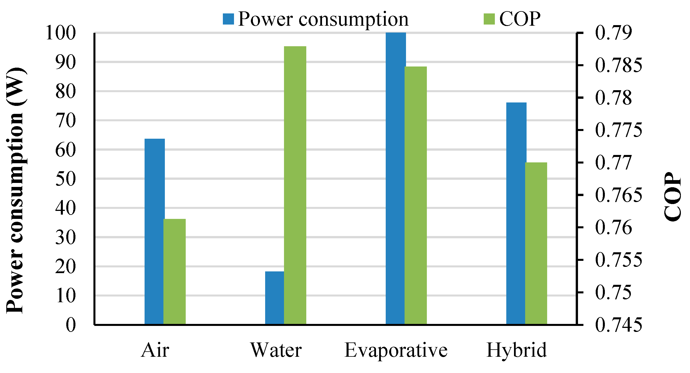
2 at an average ambient temperature of 43.5 °C. The maximum COP of 0.78 was obtained for the water cooling technique, whereas the minimum obtained was 0.76 for air cooling techniques. The maximum power of 99 W was consumed for evaporative cooling systems, whereas the minimum power of 18.12 W was consumed for water cooling systems.
Figure 10 shows the average COP and power consumption of the SVAR system for 21 October–21 January, autumn season, at 12 PM using different condenser cooling methods. The maximum heat useful for the collector obtained was 560.7 W/m
2 at an average ambient temperature of 33 °C. The maximum COP of 0.81 was obtained for the water cooling technique, whereas the minimum obtained was 0.79 for air and hybrid cooling techniques. The maximum and minimum power consumed was 104.5 W and 15.32 W for the evaporative and water cooling systems, respectively.
Figure 11 shows the average carbon dioxide (CO
2) emission liberated from each of the four different cooling methods during four consecutive seasons. The maximum emission recorded was 29.17 kg for the evaporative condenser cooling system during autumn season and a minimum of 3.35 kg for water condenser cooling during winter season.
Table 6 shows the cooling rate of different cooling methods when compared to the air-cooled condenser method. The average values in percentage for condenser cooling methods compared to the air-cooled condenser for four different months corresponding to four different seasons are presented in
Table 6. For January, the evaporative cooling method shows maximum performance with an increase of 0.62% in evaporator cooling load compared to air-cooled condenser, whereas the performance of the hybrid cooling method is 0%. Similarly, for April, water cooling recorded a maximum increase in performance with a 1.94% increase in the evaporator cooling load. In July, extreme summer is dominated by the water-cooled condenser method, reporting a 3.14% increase in the cooling load as compared to the air-cooled condenser method, followed by 2.98% and 2.45% via the evaporative and hybrid cooling methods. Water cooling also recorded a 2.11% increase in evaporator cooling followed by 0% with the hybrid cooling method.
Fixed cost is the initial cost of the total condenser cooling mechanism. In the case of air cooling, the fan cost and associated ducting cost were considered. In the case of water-cooled condenser, the cost of the heat exchanger, pumps, cooling tower with fans, and associated piping and ducting costs were considered. In the case of evaporative cooling, the cost of the evaporative spray chamber along with fans and pumps was considered. The cost data were collected from published data as well as market price from suppliers.
The average initial cost of shell and tube water-cooled heat exchangers along with cooling tower is 166 USD/kW [
39], for air-cooled condenser it is 60 USD/kW, and for evaporative it is 89 USD/kW. The cost of evaporative-cooled condensers applies to hybrid condensers as the difference is based on operating time only. Operating cost is determined from the power consumption rates as given in
Figure 5,
Figure 6,
Figure 7 and
Figure 8. The industrial electricity tariff considered here is taken as 0.069 USD/kWh [
40]. Maintenance cost is taken as 5% of the initial cost [
41]. The total cost of the condensing unit will be the sum of the initial cost plus the present day value of the operating and maintenance costs. Equation (18) is used to determine the total NPV cost using the initial cost for the 3 TR machine condenser IC, the operating cost OC, and the Maintenance cost MC. The OC and MC are calculated for 15 years (
n = 15) with a discount rate (
i) of 10%.
Results as given in
Table 6 indicate that the cooling effect is similar in all cases and the cost of operation of the condenser is the main factor determining the selection. Results indicate that hybrid cooling which involves air cooling up to a condenser temperature of 40 °C and evaporative cooling at higher temperatures incurs the lowest condenser total cost in terms of cost per unit refrigerating capacity. Analyses of the environmental effects of the different cooling methods of condensers will take into account the overall benefit achieved by enhanced cooling performance of the VAR systems. Hence, additional emissions due to the usage of drives like pumps and compressors will be overcome by savings in higher cooling performance of the systems.
4. Conclusions
The performance of a solar vapor absorption cooling machine was simulated for particular solar radiation intensity and atmospheric conditions. This result was compared with TRNSYS simulation and validated. The validated mathematical model of VAR using EES shows good agreement with the published results, which were used to generate the performance data for various condenser cooling methods for different months.
Water condenser cooling is more effective in enhancing the overall performance of the SVAR system during the year for Riyadh, KSA, followed by the evaporative condenser cooling method. The results show that the water condenser cooling method has 6%, 14%, and 8% higher COP values for spring, summer, and autumn seasons, respectively, compared to the evaporative condenser cooling method. The cooling effect produced via evaporative cooling is highest in winter, and that of water cooling in the other three seasons. Though evaporative condenser is the second most effective method for the three seasons, it is very close in performance to water cooling. Hence, the cost factor plays a key role in determining the best option.
Cost analysis was carried out by calculating the NPV for a 15-year operating period as it was seen that hybrid-cooled condensers which involve a partial air cooling and evaporative cooling showed minimum cost incurrence. The maximum 29.17 kg emission of CO2 was recorded for the evaporative condenser cooling method for autumn season concerning the ambient conditions increasing the COP by 2.98% compared to air condenser cooling.


 and
and 


