Article

Research on the Control Method of the PV Grid-Connected Inverter under an Asymmetrical Power Grid Fault

School of Mechanical and Electrical Engineering, Shihezi University, Shihezi 832007, China
*
Author to whom correspondence should be addressed.
Energies 2023, 16(22), 7504; https://doi.org/10.3390/en16227504
Submission received: 26 September 2023 / Revised: 26 October 2023 / Accepted: 7 November 2023 / Published: 9 November 2023
(This article belongs to the Section A2: Solar Energy and Photovoltaic Systems)

Abstract

:
The negative-sequence current component and harmonic components generated when an asymmetrical fault occurs in the power grid seriously affect the normal operation of the photovoltaic (PV) grid-connected inverter. In order to suppress the negative-sequence current component and the harmonic component of the grid-connected current, and to meet the normal grid-connected operation requirements of the PV grid-connected inverter when asymmetrical faults occur in the grid, this paper proposes the proportional integral double-resonant (PI-DR) current controller, which consists of the PI controller and double-resonant controllers. The PI-DR current controller can directly control the negative-sequence current component and the grid-connected current harmonic component in the output current in the forward synchronous rotating coordinate system, without decomposing the positive and negative sequence currents. The PI-DR current controller ensures that the PV grid-connected inverter can realize normal grid-connected operation and improves the quality of the power when an asymmetrical fault occurs in the power grid. MATLAB/Simulink experiments show that the PI-DR current controller can improve the dynamic characteristics of the PV grid-connected inverter and improve the operating capability of the system when an asymmetrical fault occurs in the power grid.

1. Introduction

Grid-connected inverters, as the bridge between new energy sources and the power grid, are widely used in PV grid-connected power generation and other fields because of their advantages such as high sinusoidal output current and easy adjustment of the power factor [1]. The control method of the PV grid-connected inverter will directly affect the power quality of the grid. When an asymmetrical fault occurs in the power grid, if the PV grid-connected inverter operates according to the traditional control method based on PI control in the forward synchronous rotating coordinate system, there are double-frequency fluctuations in the direct-current (DC) side bus voltage, and there is a negative-sequence component and a harmonic component in the alternating-current (AC) side current, which affects the reliable operation of the PV grid-connected inverter and the quality of the grid-connected current. Therefore, it is of great practical significance to conduct research on the control method of the PV power grid-connected inverter when an asymmetrical fault occurs in the power grid.
For the resonance problem of the grid-connected inverter, the existing control methods include capacitor current feedback active damping control, capacitor voltage feedback active damping control, and grid current feedback active damping control, and these are widely discussed in the literature [2,3,4,5,6]. Using the impedance stabilization criterion in [7,8], the method is proposed to solve the adaptive control of gain scheduling for grid-connected inverter systems. In references [9,10], the influences of different limiters on the output impedance characteristics of the grid-connected inverter are discussed, impedance analysis is used to analyze the dynamic interaction between the inverter and the grid system, and the impedance ratio is used to represent the stability margin of the grid-connected inverter system. However, these methods above are based on the grid-connected inverter itself being prone to resonance problems and research.
Many methods have been proposed to improve the quality of power output from the grid. In references [11,12,13], the crossing voltage at the PV access point is regulated by adjusting the active and reactive power of the PV grid-connected inverter to ensure stable operation of the PV grid-connected system. In reference [14], the authors proposed a time domain symmetric component extraction method under unbalanced grid conditions; the method corrects the unbalanced grid currents and provides the required active and reactive power to the grid. Improving power quality in PV grid-connected systems by comparative analysis of model predictive control in three-level and two-level inverters has been explored in [15]. In reference [16], the authors provide a deep analysis of existing active power control strategies during unbalanced voltage sags, which is highly instructive and informative. A phase-locked module based on a second-order generalized integrator combined with PI and PR control methods was investigated in the literature [17,18,19,20,21], which achieves high-quality grid power output at harmonics and unbalanced voltages. However, this method cannot achieve zero-error tracking when there is some deviation in the grid voltage and frequency.
Several control methods have been proposed in order to control the negative sequence current component. In reference [22], the negative sequence component of the grid-connected current is reduced by changing the control strategy so that the three-phase output currents are symmetrical, but there are double-frequency fluctuations in the DC bus voltage. A symmetric component control algorithm (SCCA) is proposed in the literature [23], which is applicable to four-leg three-phase grid-connected voltage source inverters, and the article also introduces a negative and zero-sequence injection mechanism based on the (d,q) current coordinate control. The SCCA can effectively improve the quality of the power. In references [24,25,26,27,28], by injecting a certain percentage of the negative-sequence current component into the grid-connected current, the double-frequency fluctuations of the DC bus are reduced. However, injecting negative sequence current components will consume a huge amount of funds. The software phase-locked loop control based on the decoupling of dual synchronous coordinate systems was studied in [29,30,31,32], which has high steady-state accuracy and can accurately extract the negative-sequence components, but it relies on phase feedback, the transition process when the grid phase changes suddenly, and the long recovery time, so there is the problem of large system overshoot.
The grid voltage proportional feedforward control can effectively suppress the disturbance of grid voltage due to the convenience of implementation. References [33,34,35], based on the proportional feedforward control, increase the error compensation loop of the current signal to achieve the same system resonance and harmonic suppression effect as the grid-connected current double closed-loop control; however, this method may destabilize the system in the case of the weak power grid. To suppress the harmonic components, PIR controllers have been proposed in the literature [36,37,38,39,40]. PIR controllers are effective in suppressing harmonics and ensuring stable system operation. However, the effectiveness of PIR controllers has only been verified in the control of low-order harmonics, and the specific depiction of the PIR controller design is lacking in the existing studies.
In summary, scholars have conducted extensive research on the control methods of grid-connected inverters, considering different operating conditions of inverters and adopting different control methods to control the inverters effectively. However, there are still some limitations that need to be studied and solved.
(1)
Most of the studies on resonance problems of grid-connected inverters are still based on the fact that grid-connected inverters themselves are prone to resonance problems. There is a lack of studies that consider the influence of external factors on the normal operation of grid-connected inverters.
(2)
In previous studies, there are fewer studies on grid-connected inverters when the asymmetrical faults occur in the grid. However, with regard to the grid-connected inverter, as an important connecting link between new energy power generation and the power grid, it is of great practical significance to carry out research on the grid-connected inverter for PV power generation under the asymmetrical fault of the power grid.
Consequently, when the asymmetrical fault occurs in the power grid, based on the research of PIR controllers, this paper proposes a PI-DR current controller for controlling positive- and negative-sequence current components and harmonic components in the forward synchronous rotating coordinate system, with the following main contributions.
(1)
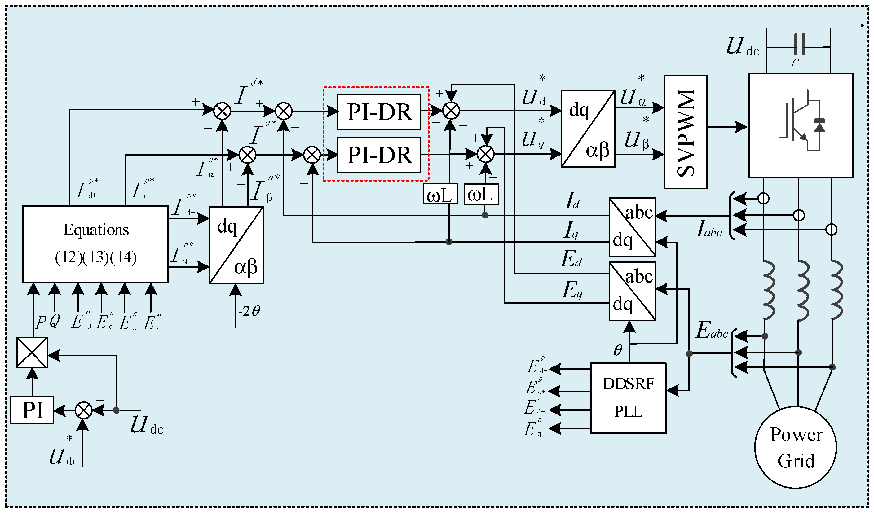
The PI-DR current controller proposed in this paper integrates double-resonant (DR) controllers on the basis of traditional PI controllers, which can realize the achieve accurate and effective control of the negative-sequence current component and harmonic component, and realize the normal grid-connected operation of the PV grid-connected inverter in the case of asymmetrical faults in the power grid.
(2)
When the asymmetrical faults occur in the grid, the PI-DR mention controller does not need to separate the positive and negative sequences of the current, and can directly control the output current in the forward synchronous rotating coordinate system without difference, and the dynamic response to the current control is faster.
(3)
Grid asymmetrical faults are frequent in power systems. The effectiveness of the PI-DR current controller proposed in this paper is verified in simulation experiments. The simulation experiments prove that the PI-DR current controller can improve the dynamic performance of the grid-connected inverter and the grid-connected power quality, and the simulation experiment results also show that the method has a certain reference value in practical engineering applications.
The remainder of this paper is arranged as follows. Firstly, the mathematical model of the PV grid-connected inverter under an asymmetrical grid fault is investigated, and secondly, the implementation principle and performance of the proposed PI-DR controller proposed in this paper are analyzed. Then, the control objectives of the grid-connected inverter under the occurrence of asymmetrical faults in the power grid are discussed, the algorithms of positive and negative sequence currents given under different control objectives are derived, and the implementation method of controlling the positive- and negative-sequence currents and harmonic components of the grid-connected inverter by using the PI-DR controller is given. Finally, the effectiveness of the PI-DR controller in controlling the negative-sequence component and harmonic component during asymmetrical faults in the grid is verified by simulation experiments.
It should be noted that the effectiveness of the control method proposed in this paper is only verified in simulation experiments, and we will carry out experimental verification in the subsequent research. However, from the results of simulation experiments, the control method proposed in this paper has a certain reference value in practical engineering applications.

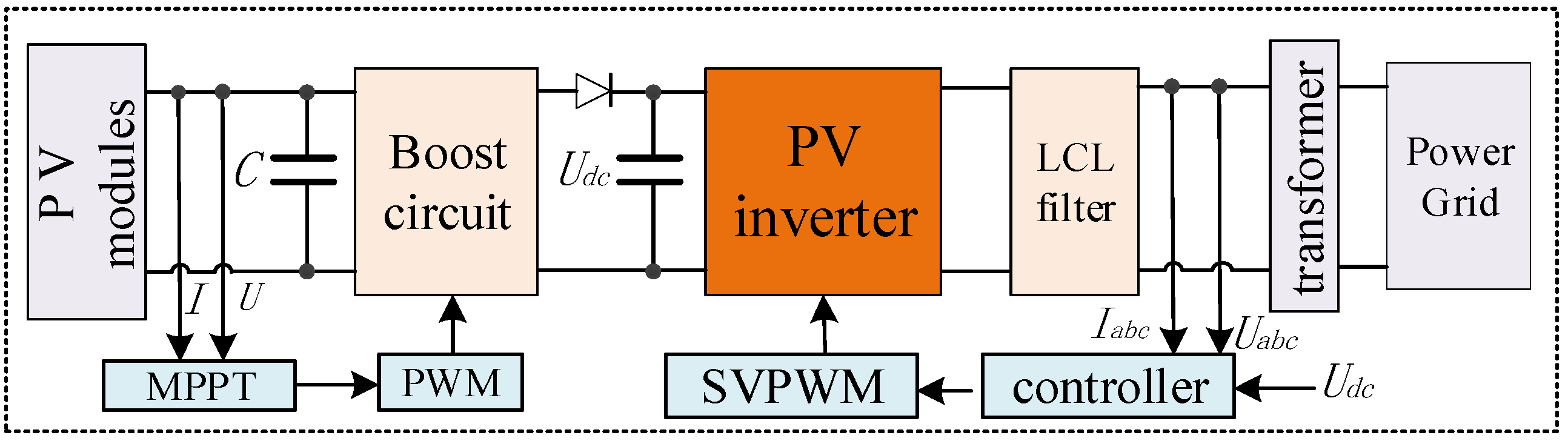
2. Structure and Mathematical Model of PV Power Generation System under Asymmetrical Power Grid Fault

2.1. Structure of PV Generation System

This paper studies the three-phase PV power generation grid-connected system, whose structure is shown in Figure 1. The direct disturbance method is used for maximum power point tracking (MPPT), and the grid-connected system adopts DC/DC boosting in the front stage and DC/AC inverter in the back stage. The inverted AC signal is filtered and connected to the grid through the transformer.

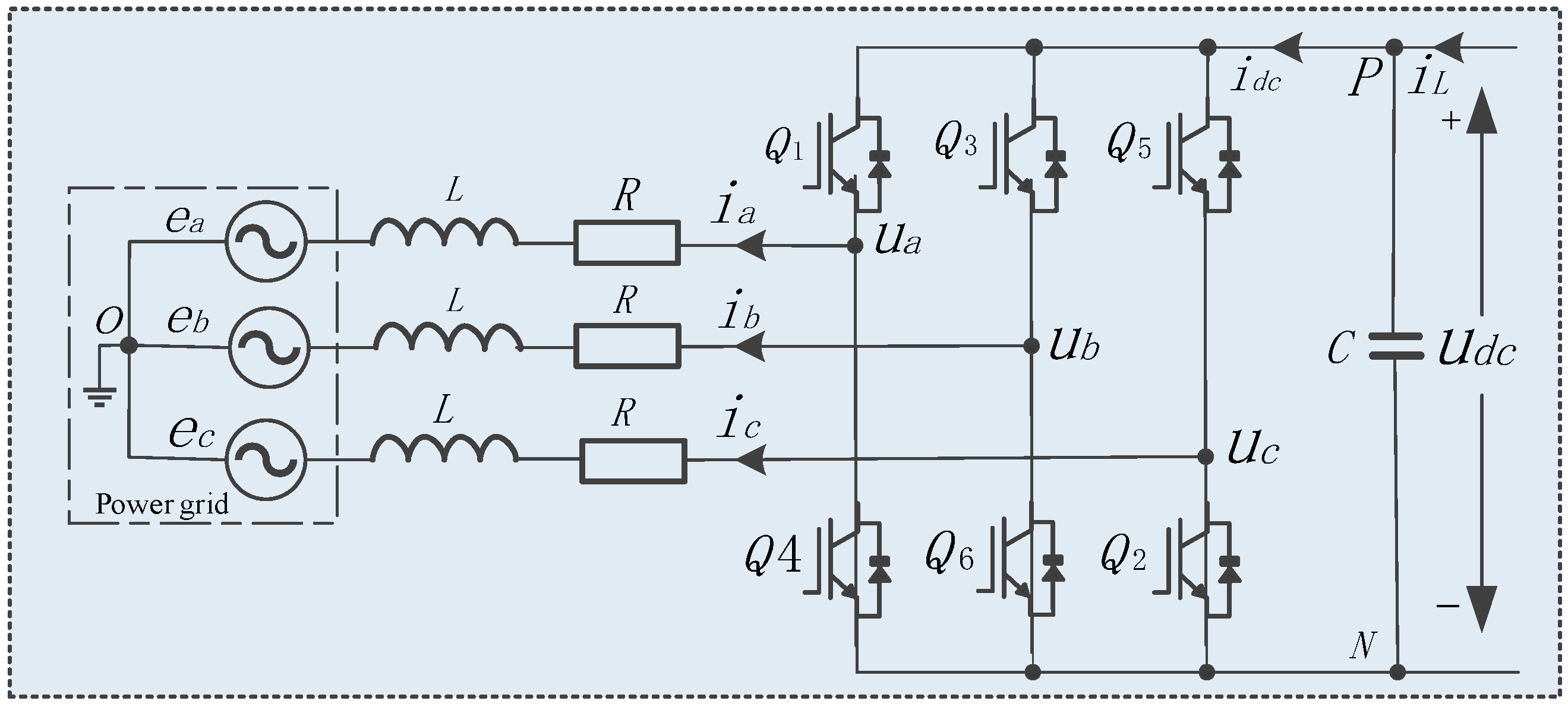
2.2. Mathematical Model of PV Grid-Connected Inverter under Asymmetrical Power Grid Fault

The topology of the PV grid-connected inverter is shown in Figure 2. The three-phase system without the neutral line does not need to consider the zero-sequence voltage component.
When the asymmetrical fault occurs in the grid, the three-phase grid voltage can be decomposed into positive and negative sequence parts, as follows:
E α β = E α β + p + E α β + n = E d q + p e j ω t + E d q n e j ω t
where
E d q + p = E d + p + j E q + p
E d q n = E d n + j E q n
E α β = 2 ( E a + E b e j 2 π / 3 + E c e j 2 π / 3 ) / 3
ω is the synchronous angular frequency of the power grid; the superscripts p and n represent the positive- and negative-sequence components, respectively; the subscripts + and − represent positive and negative synchronous rotation coordinate systems, respectively.
There are, in the forward synchronous rotating coordinate system:
E d q + = E d q + p + E d q + n = E d q + p + E d q n e j 2 ω t
From Equation (2), in the forward synchronous rotating coordinate system, there are positive-sequence DC components and negative-sequence AC components of double-frequency fluctuations in the grid voltage. The presence of the negative sequence current causes the output AC current of the PV grid-connected inverter to be asymmetric. The product of the negative-sequence current component and the switching function will generate the second harmonic component in the DC current of the inverter. The product of the second harmonic current component and the fundamental switching function will generate the third harmonic current in the AC current. In this repeated process, there are third, fifth, and seventh harmonic current components in the AC current.
Grid-connected PV power systems contain filtering devices. The filters used in the filtering device are generally low-pass filter or trap filter. Such filters are generally effective in filtering out harmonic components such as the second and third harmonics, while having no effect on harmonic components such as the fifth and seventh harmonics. Therefore, new control methods need to be investigated to accurately and effectively control the fifth and seventh harmonics when asymmetrical faults occur in the grid.
The mathematical model of the PV grid-connected inverter using the inverter current as the positive direction of the current in the stationary coordinate system is:
U α β = R I α β + L d I α β d t + E α β
where
U α β = 2 ( U a + U b e j 2 π / 3 + U c e j 2 π / 3 ) / 3 = U d q + p e j ω t + U d q n e j ω t I α β = 2 ( I a + I b e j 2 π / 3 + I c e j 2 π / 3 ) / 3 = I d q + p e j ω t + I d q n e j ω t
According to the voltage and current relationship in Equations (1)–(3), when an asymmetrical fault occurs in the grid, it can be obtained that the mathematical model of the PV grid-connected inverter after the separation of positive and negative sequences is:
U d q + p = R I d q + p + L d I d q + p d t + j ω I d q + p + E d q + p U d q n = R I d q n + L d I d q n d t j ω I d q n + E d q n
When an asymmetrical fault occurs in the power grid, the output complex power expression of the PV grid-connected inverter is:
S = P + j Q = 3 E I * 2 = 1.5 E d q + p e j ω t + E d q n e j ω t ( I d q + p e j ω t + I d q n e j ω t ) *
From Equation (6), the expressions for instantaneous active and reactive power in algebraic form are:
P = P 0 + P c 2 cos 2 ω t + P s 2 sin ( 2 ω t ) Q = Q 0 + Q c 2 cos 2 ω t + Q s 2 sin ( 2 ω t )
where P0, Q0 are the average values of P and Q, respectively; Pc2, Ps2 are the double-frequency fluctuation component amplitudes of P, respectively; Qc2, Qs2 are the double-frequency fluctuation component amplitudes of Q, respectively. The expressions are shown in the following the Equations, respectively:
P 0 = 1.5 ( E d + p I d + p + E q + p I q + p + E d n I d n + E q n I q n ) P c 2 = 1.5 ( E d p I d + p + E q p I q + p + E d + n I d n + E q + n I q n ) P s 2 = 1.5 ( E q n I d + p E d n I q + p E q + p I d n + E d + p I q n )
Q 0 = 1.5 ( E q + p I d + p E d + p I q + p + E q n I d n E d n I q n ) Q c 2 = 1.5 ( E q n I d + p E d n I q + p + E q + p I d n E d + p I q n ) Q s 2 = 1.5 ( E d n I d + p E q n I q + p + E d + p I d n + E q + p I q n )
From Equations (8) and (9), when an asymmetrical fault occurs in the power grid, the instantaneous active power and reactive power output by the PV grid-connected inverter contain second harmonic components, which will cause asymmetry in the grid-connected current and double-frequency fluctuations of DC bus voltage. Therefore, when an asymmetrical fault occurs in the power grid, the control method needs to be designed to effectively control the grid-connected current and DC bus voltage so that the PV grid-connected inverter can operate normally and reliably.

3. Control Method of the PV Power Generation Grid-Connected Inverter under Asymmetrical Grid Fault

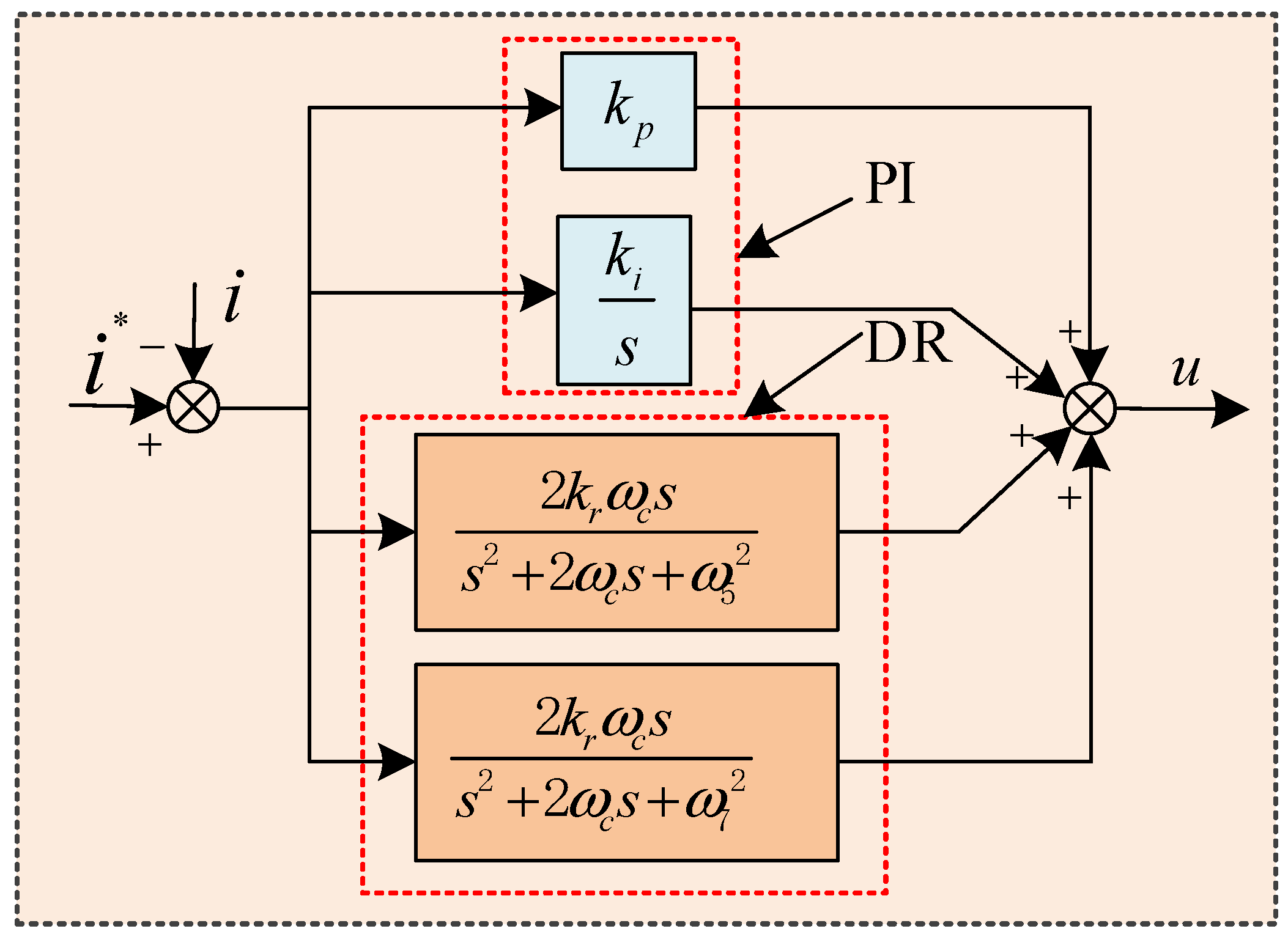
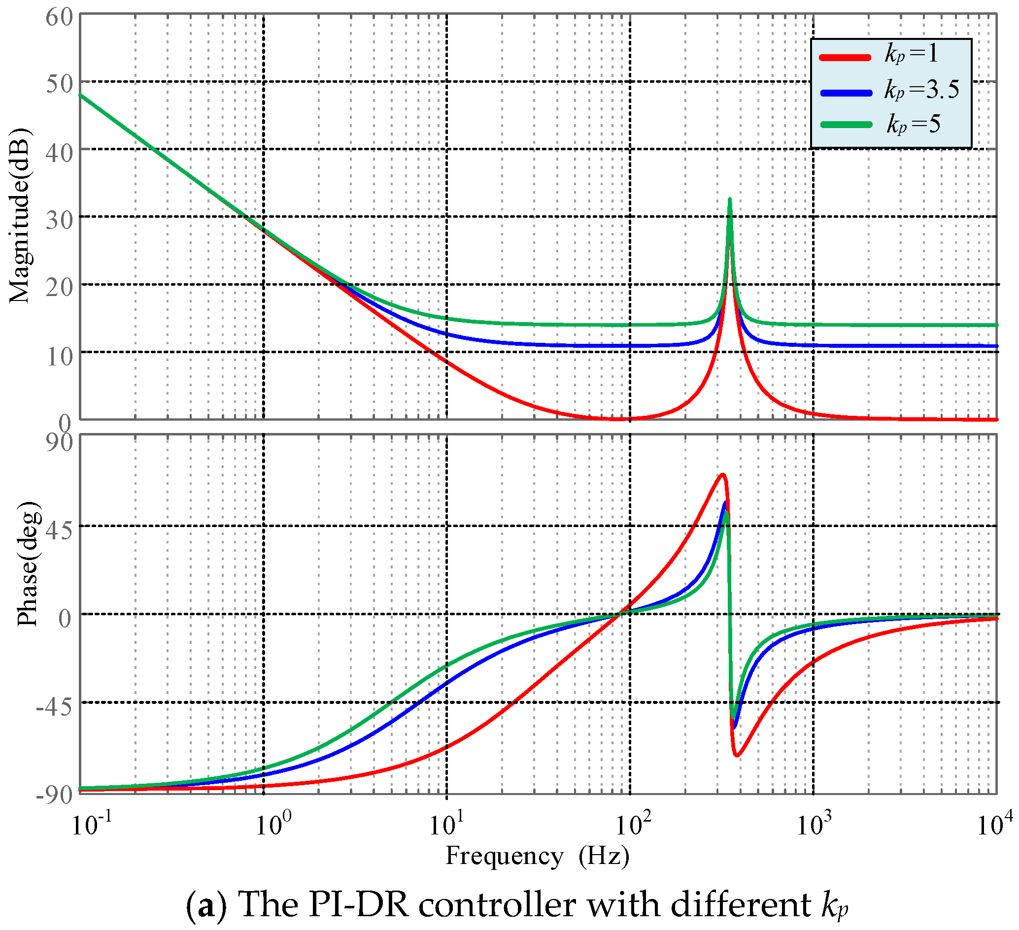
3.1. Principle of the PI-DR Controller

In the PV grid-connected inverter control system, PI control, as the traditional control method, has the advantage of quickly tracking the reference command current. However, when the asymmetrical fault occurs in the power grid, it cannot effectively control the negative-sequence component and the third and seventh harmonic components, and it is not able to effectively control the double-frequency AC component in the active and reactive power.
The PIR controller can only generate resonance at a single frequency, that is, it can only suppress the low-order harmonics of the certain frequency, and cannot effectively control the fifth and the seventh harmonics. The PIR controller transfer function is:
G P I R = k p + k i s + 2 k r ω c s s 2 + 2 ω c s + ω 0 2
In this paper, the purpose of designing the PI-DR controller is to effectively control the positive-sequence DC, negative-sequence double-frequency AC quantities, and its fifth and seventh harmonic components in the forward dq rotating coordinate system. The PI-DR controller transfer function is:
G P I D R = k p + k i s + 2 k r ω c s s 2 + 2 ω c s + ω 5 2 + 2 k r ω c s s 2 + 2 ω c s + ω 7 2
where, kp, ki, kr are the PI-DR current controller proportional, integral, and resonance coefficients; ω0 is the PIR controller’s resonant angular frequency; ωc is the cut-off angular frequency; ω5, ω7 are the fifth resonance angular frequency and seventh resonance angular frequency, respectively.
The essence of the PI-DR controller is to incorporate double-resonance (DR) controllers on the basis of the traditional PI control to achieve accurate and effective control of the negative-sequence current, the fifth and seventh harmonic components. The control schematic of the PI-DR controller is shown in Figure 3.
In order to analyze the performance of the PIR and PI-DR controllers, the Bode diagram can be obtained according to the transfer functions of PIR controller and the PI-DR controller, as shown in Figure 4. From the Bode diagram, it can be seen that the amplitude and phase margins provided by the PIR controller are relatively small, which indicates that the suppression of the high-order harmonics is weaker; however, the PI-DR controller can provide a more sufficient gain and phase margin, and the larger gain corresponds to the larger amplitude of the controller, which indicates that it can reduce the influence of the fifth and seventh harmonic components more effectively.
The main parameters of the PI-DR controller are kp, ki, kr, ωc, ω5, ω7, where ωc is the cut-off angular frequency to determine the range of resonance frequency; the larger the value of ωc, the larger the frequency range of the resonance area, generally taking the value of 5 to 15 rad/s; ω5, ω7 are the fifth resonance angular frequency and seventh resonance angular frequency, respectively, and the main elimination of the fifth and seventh harmonics in this paper. The following mainly discusses the impact on the controller and system when the kp, ki, kr changes.
Figure 5 shows the Bode diagram when different kp, ki, kr are taken, which is intended to illustrate the effect of different parameter ranges on the performance of the controller.
Figure 5a shows the Bode diagram of the PI-DR controller obtained by changing kp when the ki and kr are unchanged; it can be seen that as kp increases, the resonant frequency range decreases, which makes the controller more sensitive to the fluctuations caused by asymmetrical faults on the grid, and if kp is too small, the phase lag will be serious, so the value of kp is in the range of 1 to 5.
Figure 5b shows the Bode diagram when ki changes. It can be seen that the low-frequency gain is increased as ki is increased, but too large ki will also cause phase lag, so the value of ki that takes into account the low-frequency gain is in the range of 10 to 50.
Figure 5c shows the Bode diagram when kr changes. It can be seen that as kr increases, the gain of the resonance point increases and the range of the resonance frequency also increases; however, kr is too large to make the phase lead, and kr is too small and will reduce the gain of the resonance point and narrow the range of the resonance, so the value of kr is in the range of 10 to 100.

3.2. The Positive and Negative Sequence Current Command Calculation

When the asymmetrical fault occurs in the power grid, the different control objectives can be achieved by controlling the dq-axes containing positive- and negative-sequence currents on the grid side, respectively. These control objectives include (1) controlling the grid-connected current output by the inverter to ensure that the grid-connected current does not contain negative-sequence components and harmonic components; (2) controlling the grid-connected active power output by the inverter to eliminate the double-frequency fluctuations of the output active power; (3) controlling the grid-connected reactive power output by the inverter to eliminate the double-frequency fluctuations of the output reactive power.
Based on the mathematical model of the PV power system under an asymmetrical power grid fault, the command values of positive- and negative-sequence currents on the grid side required for the above control objectives can be obtained.
  • Objective I: Control the negative-sequence component of the grid-side current and achieve control of the fifth and seventh harmonic components, that is, i d n * = i q n * = 0 , which can be obtained from Equations (8) and (9):
i d + p * = 2 3 E d + p P 0 + E q + p Q 0 E q + p 2 + E q + p 2 i q + p * = 2 3 E q + p P 0 + E d + p Q 0 E d + p 2 + E q + p 2 i d + p * = 0 i d + p * = 0
  • Objective II: Control the second fluctuations of the grid-side active power, that is, P c 2 = P s 2 = 0 , which can be obtained from Equations (8) and (9):
I d + p * = 2 3 ( E d + p P 0 / D 1 + E q + p Q 0 / D 2 ) I q + p * = 2 3 ( E q + p P 0 / D 1 E d + p Q 0 / D 2 ) I d n * = 2 3 ( E d n P 0 / D 1 + E q n Q 0 / D 2 ) I q n * = 2 3 ( E q n P 0 / D 1 E d n Q 0 / D 2 )
where
D 1 = E d + p 2 + E q + p 2 E d n 2 E q n 2
D 2 = E d + p 2 + E q + p 2 + E d n 2 + E q n 2
  • Objective III: Control the second fluctuations of the grid-side reactive power, that is, Q c 2 = Q s 2 = 0 , which can be obtained from Equations (8) and (9):
I d + p * = 2 3 ( E d + p P 0 / D 2 + E q + p Q 0 / D 1 ) I q + p * = 2 3 ( E q + p P 0 / D 2 E d + p Q 0 / D 1 ) I d n * = 2 3 ( E d n P 0 / D 2 E q n Q 0 / D 1 ) I q n * = 2 3 ( E q n P 0 / D 2 + E d n Q 0 / D 1 )
where
D 1 = E d + p 2 + E q + p 2 E d n 2 E q n 2
D 2 = E d + p 2 + E q + p 2 + E d n 2 + E q n 2

3.3. The PV Grid-Connected Inverter Control System Design

When an asymmetrical fault occurs in the grid, the key to achieve the above control objectives is the accurate control of the positive- and negative-sequence currents of the grid-connected inverter. The PI-DR current controller proposed and designed in this paper can accurately control the positive- and negative-sequence currents under the forward synchronous rotating coordinate system without decomposing the positive- and negative-sequence currents.
From Equation (5), the voltage Equation of the grid-side inverter in vector form including the positive- and negative-sequence components in the forward synchronous rotating coordinate system can be obtained:
U d q + * = R I d q + + L d I d q + d t + j ω L I d q + + E d q +
where U d q + * is the commanded value of the grid-connected inverter voltage in the forward synchronous rotating coordinate system.
The control Equation designed using the PI-DR current controller proposed in this paper without decomposing the positive- and negative-sequence currents is:
U d q + = k p + k i s + 2 k r ω c s s 2 + 2 ω c s + ω 5 2 + 2 k r ω c s s 2 + 2 ω c s + ω 7 2 ( I d q + * I d q + )
In order to achieve decoupling control of the dq-axis current and improve the response speed of the current control, the Equation of the output voltage can be obtained by adding the decoupling and feedforward components:
U d q + * = U d q + + j ω L I d q + + E d q +
Equation (17) is decomposed into the form of d+ and q+ components in the forward synchronous speed rotating coordinate system, as follows:
U d + * = U d + j ω L I d q + + E d + U q + * = U q + + j ω L I d q + + E q +
U d + * = k p + k i s + 2 k r ω c s s 2 + 2 ω c s + ω 5 2 + 2 k r ω c s s 2 + 2 ω c s + ω 7 2 ( I d + * I d + ) U q + * = k p + k i s + 2 k r ω c s s 2 + 2 ω c s + ω 5 2 + 2 k r ω c s s 2 + 2 ω c s + ω 7 2 ( I q + * I q + )
Combined with the positive- and negative-sequence current command calculations in Section 3.2, and from Equations (18) and (19), the current control system of the PV grid-connected inverter under an asymmetrical fault in the power grid can be designed, as shown in Figure 6.
Because this control system is implemented in the forward synchronous rotating coordinate system, the negative-sequence component is manifested as a double-frequency fluctuation component, so it is necessary to transform the negative sequence current command into the forward synchronous rotating coordinate system and add it to the positive-sequence current command value to obtain the current command value, and the current feedback value only needs to be transformed into the forward synchronous rotating coordinate system using traditional methods, without decomposing the positive- and negative-sequence currents. Therefore, the PI-DR current controller can achieve accurate control of the negative-sequence current, realize the normal grid-connected operation of the PV grid-connected inverter, and ensure the dynamic response of the power system, when an asymmetrical fault occurs in the power grid.

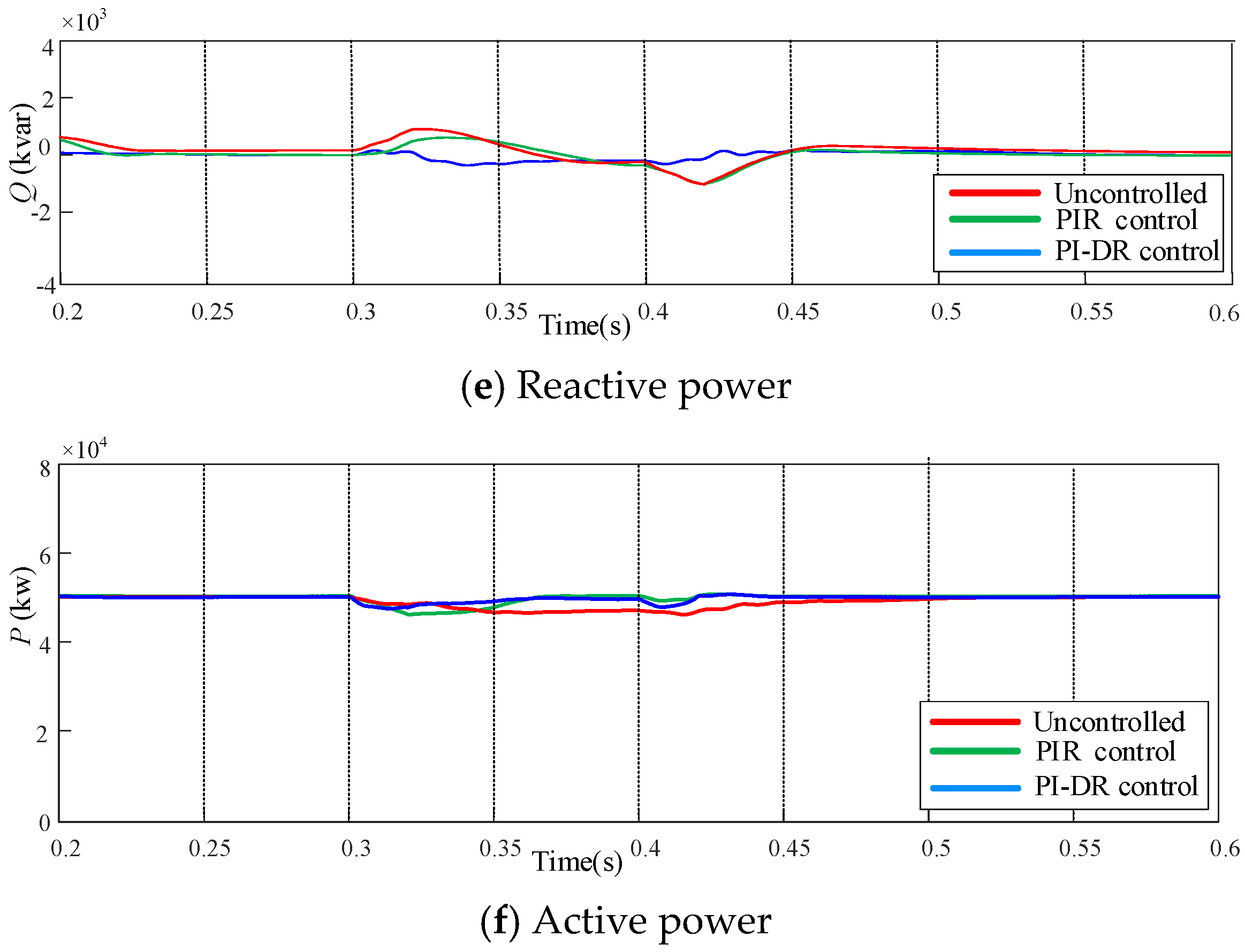
4. Simulation and Results

In this paper, simulation experiments are carried out in MATLAB/Simulink to verify the effectiveness of the theoretical analysis and the proposed control method in the case of asymmetrical fault in the power grid. The simulation experimental parameters of the PV grid-connected inverter are shown in Table 1. In this paper, the two-phase grounded short-circuit faults in asymmetrical faults in power grids are studied, to investigate the response characteristics of the system under a grid asymmetrical fault, and to compare the control performance of the PIR controller and the PI-DR controller. During the simulation experiments, it is set that the power grid has an asymmetrical fault at 0.3 s–0.4 s.
Figure 7 show the simulation comparison results of the PV grid-connected current, the DC bus voltage, the dq-axis current, the active power, and the reactive power under the PIR controller and PI-DR controller, respectively.
In order to better illustrate the control effect of the PI-DR controller proposed in this paper, the comparison results between the PIR controller and the PI-DR current controller can be obtained through simulation experiments, as shown in Table 2. I (%), Id (%), Iq (%), Udc (%) in Table 2 are the current and current dq-axis components’ unbalance degree and bus voltage unbalance degree caused by an asymmetrical fault of the power grid; P and Q denote the magnitude of fluctuation when an asymmetrical fault occurs in the grid, respectively.
From the comparison in Table 2, it can be seen that the PI-DR control is more effective than the PIR control in reducing the unbalance degree caused by an asymmetrical fault in the grid.
It can be seen from the simulation results in Figure 7a and Table 2 that when an asymmetrical fault occurs in the grid during 0.3 s–0.4 s, and due to the presence of the positive -sequence DC and negative-sequence AC components as well as the fifth and seventh harmonics, there is the sharp fluctuation in the inverter output current without any control, and the fluctuation of the inverter output current can be suppressed when the PIR control is used, but the three-phase currents are still unbalanced. Compared with the PIR control, the PI-DR controller designed in this paper has a better control effect, which can better control the negative-sequence currents and harmonic components, and the three-phase current sinusoidal degree is better, and the PI-DR controller can ensure that the three-phase balance of the inverter output current occurs during the asymmetrical faults in the grid.
Figure 7b and Table 2 show that when an asymmetrical fault occurs in the grid, the DC bus voltage will oscillate violently without control, and the DC bus present voltage contains double-frequency fluctuations, and compared with the use of the PIR control, the PI-DR controller eliminates the double-frequency fluctuations, and effectively controls the DC bus voltage to remain constant during the asymmetrical fault in the grid.
It can be seen from Figure 7c,d and Table 2 that when an asymmetrical fault occurs in the power grid, the PI-DR current controller effectively controls the dq-axis grid-side currents containing double-frequency components, negative-sequence components, and the fifth and seventh harmonic components under the forward synchronous rotating coordinate system, and compared to the PIR control, the PI-DR current controller can better control the fluctuations of the d-axis and q-axis currents during asymmetrical faults in the grid, and the PI-DR current controller can better achieve the control objective when the asymmetrical fault occurs in the grid.
Figure 7e,f and Table 2 shows that asymmetrical faults occurring in the grid will have an impact on the active and reactive power, which will cause the active and reactive power to fluctuate during the fault. Compared with the PIR control, the PID-R current controller can effectively eliminate the double-frequency fluctuations in the output active and reactive power, and can better control the impact on active and reactive power when the asymmetrical fault occurs in the grid, and the PI-DR controller has a better control effect compared with the PIR controller.

5. Conclusions

This paper analyzes the mathematical model of the PV grid-connected inverter when an asymmetrical fault occurs in the power grid. It can be seen that the DC bus voltage, output instantaneous active power, and reactive power all contain a double-frequency fluctuation component, and in the negative-sequence component will produce the fifth and seventh harmonic component, and the asymmetrical fault of the power grid will affect the PV grid-connected inverter normal operation. Therefore, this paper proposes that the PI-DR controller can directly and effectively control the output current in the forward synchronous rotating coordinate system, without decomposing the positive- and negative-sequence currents. Through simulation experiments, the following conclusions were drawn:
  • The PI-DR controller is based on the traditional PI control and incorporates DR controllers; when an asymmetrical fault occurs in the grid, the PI and the DR controllers work together. Therefore, when an asymmetrical fault occurs in the grid, the PI-DR controller can guarantee the normal grid-connected operation of the PV inverter.
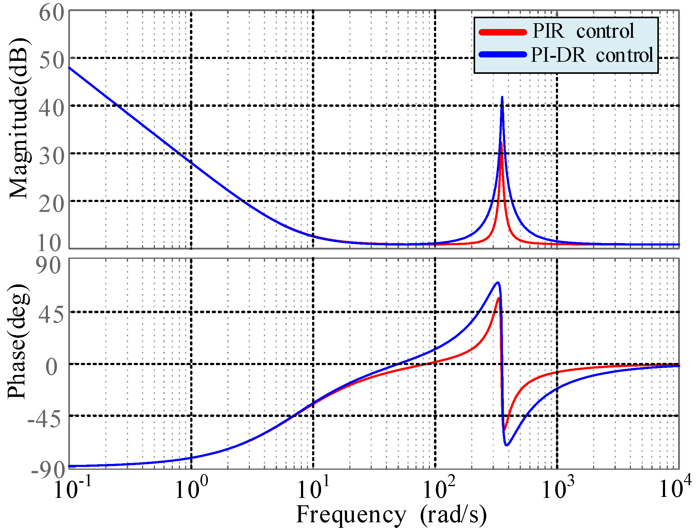
  • The PI-DR controller can provide infinite gain to the signal at the point of resonance frequency; therefore, it can achieve accurate and effective control of the negative-sequence current component of the double-frequency fluctuation and the fifth and seventh harmonic components in the forward synchronous rotating coordinate system.
  • The PI-DR controller has a faster dynamic response to current control because it does not require positive- and negative-sequence decomposition.
  • The PI-DR current controller can improve the grid-connected power quality, and the results of the simulation experiments show that the PI-DR controller has some reference value in practical engineering applications.

Author Contributions

Conceptualization, S.T. and M.L.; methodology, S.T.; software, S.T.; validation, M.L., R.W. and D.L.; formal analysis, R.W.; investigation, D.L.; resources, D.L.; data curation, R.W.; writing—original draft preparation, S.T.; writing—review and editing, M.L.; visualization, S.T.; supervision, D.L.; project administration, M.L; funding acquisition, M.L. All authors have read and agreed to the published version of the manuscript.

Funding

This research was funded by Research on Voltage Source Type PV Equipment, Cooperative Control and Multi-Scenario Support Technology, grant number 2022A01004-3.

Data Availability Statement

Data are contained within the article.

Conflicts of Interest

The authors declare no conflict of interest.

References

  1. Zhang, Y.; Chao, Q.; Wu, C.Y.; Xu, L.J. Researching Review of Photovoltaic Grid-Connected Inverter. Electr. Energy Manag. Technol. 2016, 17, 12–16. [Google Scholar]
  2. Zhang, M.; Wang, J.; Zhang, S.; Gao, L.; Guo, X.; Chen, L.; Xu, Y. Harmonic Resonance Analysis and Impedance Remodeling Method of Multi-Inverter Grid-Connected System. Electronics 2023, 12, 3684. [Google Scholar] [CrossRef]
  3. Liu, J.; Zhou, L.; Molinas, M. Damping region extension for digitally controlled LCL-type grid-connected inverter with capacitor-current feedback. IET Power Electron. 2018, 11, 1974–1982. [Google Scholar] [CrossRef]
  4. Pan, D.; Ruan, X.; Bao, C.; Li, W.; Wang, X. Capacitor-current-feedback active damping with reduced computation delay for improving robustness of LCL-type grid-connected inverter. IEEE Trans. Power Electron. 2014, 29, 3414–3427. [Google Scholar] [CrossRef]
  5. Yang, D.; Ruan, X.; Wu, H. A Real-time computation method with dual sampling mode to improve the current control performance of the LCL type grid-connected inverter. IEEE Trans. Ind. Electron. 2015, 62, 4563–4572. [Google Scholar] [CrossRef]
  6. Zhao, X.; Yang, H.G. LCL grid connected inverter control strategy based on two-degree-of-freedom internal model control. Mod. Electr. Power 2018, 6, 86–91. [Google Scholar]
  7. Zhong, P.; Sun, J.; Tian, Z.; Huang, M.; Yu, P.; Zha, X. An Improved Impedance Measurement Method for Grid-Connected Inverter Systems Considering the Background Harmonics and Frequency Deviation. IEEE J. Emerg. Sel. Top. Power Electron. 2021, 9, 4236–4247. [Google Scholar] [CrossRef]
  8. Cespedes, M.; Sun, J. Adaptive control of grid-connected inverters based on online grid impedance measurements. IEEE Trans. Sustain. Energy 2014, 5, 516–523. [Google Scholar] [CrossRef]
  9. Cui, X.; Wu, J.; Liu, X.; Chen, Y.; Xie, Z.; Xue, F.; Liu, Y.; Luo, C. Large-Signal Impedance Modeling and Stability Analysis of a Grid-Connected Inverter Considering the Influence of a Limiter in Different Control Links. Energies 2023, 16, 6227. [Google Scholar] [CrossRef]
  10. Chen, J.; Yan, Z.Y.; Zhao, B. On the impedance Modelling and Grid-connected Characteristics of the Three-phase Droop Controlled Inverter. Proc. CSEE 2019, 16, 4846–4856. [Google Scholar]
  11. Tong, X.; Zhong, M.; Zhang, X.; Deng, J.; Zhang, Z. Voltage regulation strategy of AC distribution network based on distributed PV grid-connected inverter. J. Eng. 2019, 16, 2525–2528. [Google Scholar] [CrossRef]
  12. Zhang, Y.; Wang, J.-M.; Zhu, P.; Yao, J.; Yang, G.-H. Research on control strategy of three phase photovoltaic grid-connected inverter based on virtual flux. Electr. Meas. Instrum. 2015, 52, 41–45. [Google Scholar]
  13. Jiang, R.; Jiang, T.; Xu, L. Research on Inverter Control Strategy of PV Integrated into Distribution Network. Electr. Eng. 2017, 12, 96–100. [Google Scholar]
  14. Alathamneh, M.; Ghanayem, H.; Yang, X.; Nelms, R.M. Three-Phase Grid-Connected Inverter Power Control under Unbalanced Grid Conditions Using a Time-Domain Symmetrical Components Extraction Method. Energies 2022, 15, 6936. [Google Scholar] [CrossRef]
  15. Gada, S.; Fekik, A.; Mahdal, M.; Vaidyanathan, S.; Maidi, A.; Bouhedda, A. Improving Power Quality in Grid-Connected Photovoltaic Systems: A Comparative Analysis of Model Predictive Control in Three-Level and Two-Level Inverters. Sensors 2023, 23, 7901. [Google Scholar] [CrossRef]
  16. Cupertino, A.F.; Xavier, L.S.; Brito, E.M.; Mendes, V.F.; Pereira, H.A. Benchmarking of power control strategies for photovoltaic systems under unbalanced conditions. Int. J. Power Energy Syst. 2018, 106, 335–345. [Google Scholar] [CrossRef]
  17. Ouyang, S.; Ma, W.J. Control strategy for PV inverter under unbalanced grid voltage. Appl. Electron. Technol. 2018, 44, 147–150. [Google Scholar] [CrossRef]
  18. Xu, H.C.; Teng, Y.F.; Wang, X.R. A control strategy combining repetitive control and quasi-PR control for PMSG grid-side converter. Power Syst. Prot. Control 2018, 5, 153–156. [Google Scholar]
  19. Peng, C.; Heng, N. Torque Ripple Restraint Strategy of DFIG Under Unbalanced Grid Voltage Conditions Based on Resonant Control Loop. Proc. CSEE 2015, 35, 1756–1767. [Google Scholar]
  20. Jiang, Y.; Li, Y.; Tian, Y.; Wang, L. Phase-Locked Loop Research of Grid-Connected Inverter Based on Impedance Analysis. Energies 2018, 11, 3077. [Google Scholar] [CrossRef]
  21. Tiwari, R.; Babu, N.R.; Arunkrishna, R.; Sanjeevikumar, P. Comparison Between PI Controller and Fuzzy Logic-Based Control Strategies for Harmonic Reduction in Grid-Integrated Wind Energy Conversion System. In Advances in Smart Grid and Renewable Energy, Proceedings of the ETAEERE-2016, Majhitar, Sikkim, 17–18 December 2016; Springer: Singapore, 2018; pp. 978–981. [Google Scholar]
  22. Arulkumar, K.; Vijayakumar, D.; Palanisamy, K. Modeling and control strategy of three phase neutral point clamped multilevel PV inverter connected to the grid. J. Build. Eng. 2015, 3, 195–202. [Google Scholar] [CrossRef]
  23. Abbassi, R.; Marrouchi, S.; Saidi, S.; Abbassi, A.; Chebbi, S. Optimal Energy Management Strategy and Novel Control Approach for DPGSs Under Unbalanced Grid Faults. J. Circuits Syst. Comput. 2019, 28, 1950057. [Google Scholar] [CrossRef]
  24. Alepuz, S.; Calle, A.; Busquets-Monge, S.; Kouro, S.; Wu, B. Use of Stored Energy in PMSG Rotor Inertia for Low-Voltage Ride-Through in Back-to-Back NPC Converter-Based Wind Power Systems. IEEE Trans. Ind. Electron. 2013, 60, 1787–1796. [Google Scholar] [CrossRef]
  25. Femat, R.; Vázquez, N.; Vazquez, E. Current Control Based on Limit Cycle Stability for Photovoltaic Arrays. IET Renew. Power Gener. 2020, 14, 725–733. [Google Scholar]
  26. Cao, N.; Cao, Y.; Liu, J. Modeling and Analysis of Grid-Connected Inverter for PV Generation. Adv. Mater. Res. 2013, 760–762, 451–456. [Google Scholar] [CrossRef]
  27. Haddadi, A.; Kocar, I.; Mahseredjian, J.; Karaagac, U.; Farantatos, E. Negative sequence quantities-based protection under inverter-based resources—Challenges and impact of the German grid code. Electr. Power Syst. Res. 2020, 188, 106573. [Google Scholar] [CrossRef]
  28. Zhang, W.; Wang, Y.; Xu, P.; Li, D.; Liu, B. A Current Control Method for Grid-Connected Inverters. Energies 2023, 16, 6558. [Google Scholar] [CrossRef]
  29. Lu, D.D.; Fang, M. Simulation Study of Software Phase-Locked Loop Based on the Synchronous Reference Frame for Three-phase Grid. J. Huaiyin Inst. Technol. 2015, 24, 26–30. [Google Scholar]
  30. Zhuang, Y.; Xu, W.M.; Li, S.Q. Research on the Control System of the Inverter about Distributed Photovoltaic Generation. Electric Switchgear. 2019, 4, 60–62, 68. [Google Scholar]
  31. Le, K.A.; Ai, X.; Dang, N.H. Hierarchical control strategy for voltage unbalance compensation in micro-grid. J. Harbin Inst. Technol. 2016, 48, 46–52. [Google Scholar]
  32. Lin, C.W.; Liu, T.J.; Gui, J. Double Closed-Loop Control of the Three-Level Rectifier Based on Synchronous PI Current Decoupling. Appl. Mech. Mater. 2013, 385–386, 1179–1183. [Google Scholar] [CrossRef]
  33. Yang, X.; Wang, T.; Xu, Y. Voltage feedforward control of LCL grid-connected inverter based on virtual inductor. Acta Energiae Solaris Sin. 2020, 41, 56–63. [Google Scholar]
  34. Subramanian, S.B.; Varma, R.K.; Vanderheide, T. Impact of grid voltage feed-forward filters on coupling between DC link voltage and AC Voltage controllers in smart PV solar systems. IEEE Trans. Sustain. Energy 2020, 11, 381–390. [Google Scholar] [CrossRef]
  35. Zhao, Q.L.; Song, W.L.; Yuan, J. Research on grid-connected inverter stability based on current error signal compensation in weak grid. Acta Energiae Solaris Sin. 2019, 40, 2833–2841. [Google Scholar]
  36. Zhang, X.; Zhang, G.; Qian, J.L. Design of PIR Controller with the Ability of Low Harmonic Damping. Trans. China Electrotech. Soc. 2016, 31, 19–27. [Google Scholar]
  37. El Karkri, Y.; Rey-Boué, A.B.; El Moussaoui, H.; Stöckl, J.; Strasser, T.I. Improved Control of Grid-connected DFIG-based Wind Turbine using Proportional-Resonant Regulators during Unbalanced Grid. Energies 2019, 12, 4041. [Google Scholar] [CrossRef]
  38. Liu, B.; Zie, J.J.; Li, J.; Wu, J.J. Novel Grid-Connected Current Control Strategies Based on Self-Adaptive Proportional-Resonant. Trans. China Electrotech. Soc. 2013, 28, 186–195. [Google Scholar]
  39. Dai, Z.W.; Shu, J.; Wu, C.H.; Wang, H.; Song, X.R.; Zhang, W. Study on control strategy of photovoltaic grid-connected inverter based on LC filter. Adv. New Renew. Energy 2014, 2, 453–499. [Google Scholar]
  40. Pan, J.J.; Liu, Y.X.; Sun, H.N.; Zhang, Q.J.; Liu, M.Y. Control Strategy of LCL-Filtered Grid-Connected Inverter Based on Quasi-Proportional Resonant and Grid Voltage Feed-Forward. Electr. Mach. Control Appl. 2016, 43, 23–27. [Google Scholar]
Figure 1. Structure of the PV power generation system.
Energies 16 07504 g001
Figure 2. The topology of the PV power generation grid-connected inverter.
Energies 16 07504 g002
Figure 3. The PI-DR control schematic diagram.
Energies 16 07504 g003
Figure 4. Bode diagram of the PIR controllers and PI-DR controllers.
Energies 16 07504 g004
Figure 5. The Bode diagram of the PI-DR controller with different parameters: (a) The PI-DR controller with different kp; (b) The PI-DR controller with different ki; (c) The PI-DR controller with different kr.
Energies 16 07504 g005aEnergies 16 07504 g005b
Figure 6. Control system of the PV grid-connected inverter under asymmetrical fault in power grid.
Energies 16 07504 g006
Figure 7. (a) The PV grid-connected current; (b) The DC bus voltage; (c) d-axis current; (d) q-axis current; (e) reactive power; (f) active power.
Energies 16 07504 g007aEnergies 16 07504 g007b
Table 1. The PV grid-connected inverter simulation parameters.
ParameterValue
Grid-side voltage Un/V380
DC side voltage Udc/V600
Grid-side filtering inductance L/mH6
DC-side support capacitor C/mF1.5
Switching frequency fs/kHz6
Table 2. Comparison of the control effectiveness of different control methods under asymmetrical fault occurrence in the power grid.
Control StrategyI (%)Id (%)Iq (%)Udc (%)QP
Uncontrolled3.964.754.833.632.762.85
PI-R control1.531.891.911.321.251.14
PI-DR control0.280.630.810.540.180.09
Disclaimer/Publisher’s Note: The statements, opinions and data contained in all publications are solely those of the individual author(s) and contributor(s) and not of MDPI and/or the editor(s). MDPI and/or the editor(s) disclaim responsibility for any injury to people or property resulting from any ideas, methods, instructions or products referred to in the content.

