
The Potential Effect on the Performance of CrN/Cr-Coated SS316L Bipolar Plates and Their Durability in Simulated Cathodic HT-PEFC Environments


Abstract
:1. Introduction
2. Experimental Details
3. Results and Discussion
4. Conclusions
Author Contributions
Funding
Data Availability Statement
Acknowledgments
Conflicts of Interest
References
- Haider, R.; Wen, Y.; Ma, Z.-F.; Wilkinson, D.P.; Zhang, L.; Yuan, X.; Song, S.; Zhang, J. High temperature proton exchange membrane fuel cells: Progress in advanced materials and key technologies. Chem. Soc. Rev. 2021, 50, 1138–1187. [Google Scholar] [CrossRef]
- Rosli, R.E.; Sulong, A.B.; Daud, W.R.W.; Zulkifley, M.A.; Husaini, T.; Rosli, M.I.; Majlan, E.H.; Haque, M.A. A review of high-temperature proton exchange membrane fuel cell (HT-PEMFC) system. Int. J. Hydrogen Energy 2017, 42, 9293–9314. [Google Scholar] [CrossRef]
- Ni, M.; Leung, D.Y.C.; Leung, M.K.H. A review on reforming bio-ethanol for hydrogen production. Int. J. Hydrogen Energy 2007, 32, 3238–3247. [Google Scholar] [CrossRef]
- Rostrup-Nielsen, J.R.; Sehested, J.; Nørskov, J.K. Hydrogen and synthesis gas by steam- and C02 reforming. Adv. Catal. 2002, 47, 65–139. [Google Scholar] [CrossRef]
- Ito, H.; Maeda, T.; Nakano, A.; Takenaka, H. Properties of Nafion membranes under PEM water electrolysis conditions. Int. J. Hydrogen Energy 2011, 36, 10527–10540. [Google Scholar] [CrossRef]
- Li, R. Coatings for Metallic Bipolar Plates in High-Temperature Polymer Electrolyte Fuel Cells; Forschungszentrum Jülich GmbH, Zentralbibliothek: Jülich, Germany, 2019; Volume 472. [Google Scholar]
- Oh, K.; Ju, H. Temperature dependence of CO poisoning in high-temperature proton exchange membrane fuel cells with phosphoric acid-doped polybenzimidazole membranes. Int. J. Hydrogen Energy 2015, 40, 7743–7753. [Google Scholar] [CrossRef]
- Barreras, F.; Lozano, A.; Roda, V.; Barroso, J.; Martín, J. Optimal design and operational tests of a high-temperature PEM fuel cell for a combined heat and power unit. Int. J. Hydrogen Energy 2014, 39, 5388–5398. [Google Scholar] [CrossRef]
- Chandan, A.; Hattenberger, M.; El-Kharouf, A.; Du, S.; Dhir, A.; Self, V.; Pollet, B.G.; Ingram, A.; Bujalski, W. High temperature (HT) polymer electrolyte membrane fuel cells (PEMFC)—A review. J. Power Sources 2013, 231, 264–278. [Google Scholar] [CrossRef]
- Pinar, F.J.; Pilinski, N.; Wagner, P. Long-term testing of a high temperature polymer electrolyte membrane fuel cell: The effect of reactant gases. AIChE J. 2016, 62, 217–227. [Google Scholar] [CrossRef]
- Sharaf, O.Z.; Orhan, M.F. An overview of fuel cell technology: Fundamentals and applications. Renew. Sustain. Energy Rev. 2014, 32, 810–853. [Google Scholar] [CrossRef]
- Authayanun, S.; Im-Orb, K.; Arpornwichanop, A. A review of the development of high temperature proton exchange membrane fuel cells. Cuihua Xuebao/Chin. J. Catal. 2015, 36, 473–483. [Google Scholar] [CrossRef]
- Samsun, R.C.; Pasel, J.; Janßen, H.; Lehnert, W.; Peters, R.; Stolten, D. Design and test of a 5kWe high-temperature polymer electrolyte fuel cell system operated with diesel and kerosene. Appl. Energy 2014, 114, 238–249. [Google Scholar] [CrossRef]
- Weissbecker, V.; Reimer, U.; Wippermann, K.; Lehnert, W. A Comprehensive Corrosion Study on Metallic Materials for HT-PEFC Application. ECS Trans. 2013, 58, 693–704. [Google Scholar] [CrossRef]
- Manso, A.P.; Marzo, F.F.; Garicano, X.; Alegre, C.; Lozano, A.; Barreras, F. Corrosion behavior of tantalum coatings on AISI 316L stainless steel substrate for bipolar plates of PEM fuel cells. Int. J. Hydrogen Energy 2020, 45, 20679–20691. [Google Scholar] [CrossRef]
- Alegre, C.; Álvarez-Manuel, L.; Mustata, R.; Valiño, L.; Lozano, A.; Barreras, F. Assessment of the durability of low-cost Al bipolar plates for High Temperature PEM fuel cells. Int. J. Hydrogen Energy 2019, 44, 12748–12759. [Google Scholar] [CrossRef]
- Yang, L.X.; Liu, R.J.; Wang, Y.; Liu, H.J.; Zeng, C.L.; Fu, C. Corrosion and interfacial contact resistance of nanocrystalline β-Nb2N coating on 430 FSS bipolar plates in the simulated PEMFC anode environment. Int. J. Hydrogen Energy 2021, 46, 32206–32214. [Google Scholar] [CrossRef]
- Ingle, A.V.; Raja, V.S.; Rangarajan, J.; Mishra, P. Corrosion resistant quaternary Al–Cr–Mo–N coating on type 316L stainless steel bipolar plates for proton exchange membrane fuel cells. Int. J. Hydrogen Energy 2020, 45, 3094–3107. [Google Scholar] [CrossRef]
- Yan, W.M.; Chen, C.Y.; Liang, C.H. Comparison of performance degradation of high temperature PEM fuel cells with different bipolar plates. Energy 2019, 186, 115836. [Google Scholar] [CrossRef]
- Gao, P.; Xie, Z.; Wu, X.; Ouyang, C.; Lei, T.; Yang, P.; Liu, C.; Wang, J.; Ouyang, T.; Huang, Q. Development of Ti bipolar plates with carbon/PTFE/TiN composites coating for PEMFCs. Int. J. Hydrogen Energy 2018, 43, 20947–20958. [Google Scholar] [CrossRef]
- Jin, J.; Hu, M.; Zhao, X. Investigation of incorporating oxygen into TiN coating to resist high potential effects on PEMFC bipolar plates in vehicle applications. Int. J. Hydrogen Energy 2020, 45, 23310–23326. [Google Scholar] [CrossRef]
- Silva, F.; Ramirez, O.P.; Tunes, M.; Edmondson, P.; Sagás, J.; Fontana, L.; de Melo, H.; Schön, C. Corrosion resistance of functionally graded TiN/Ti coatings for proton exchange membrane fuel cells. Int. J. Hydrogen Energy 2020, 45, 33993–34010. [Google Scholar] [CrossRef]
- Lee, E.-K.; Kim, J.-K.; Kim, T.-J.; Song, H.; Kim, J.-H.; Park, S.-A.; Jeong, T.-G.; Yun, S.-W.; Lee, J.; Goo, J.; et al. Enhanced corrosion resistance and fuel cell performance of Al1050 bipolar plate coated with TiN/Ti double layer. Energy Convers. Manag. 2013, 75, 727–733. [Google Scholar] [CrossRef]
- Peng, S.; Xu, J.; Li, Z.; Jiang, S.; Munroe, P.; Xie, Z.-H.; Lu, H. A reactive-sputter-deposited TiSiN nanocomposite coating for the protection of metallic bipolar plates in proton exchange membrane fuel cells. Ceram. Int. 2020, 46, 2743–2757. [Google Scholar] [CrossRef]
- Feng, K.; Li, Z.; Sun, H.; Yu, L.; Cai, X.; Wu, Y.; Chu, P.K. C/CrN multilayer coating for polymer electrolyte membrane fuel cell metallic bipolar plates. J. Power Sources 2013, 222, 351–358. [Google Scholar] [CrossRef]
- Zhang, M.; Lin, G.; Wu, B.; Shao, Z. Composition optimization of arc ion plated CrN x films on 316L stainless steel as bipolar plates for polymer electrolyte membrane fuel cells. J. Power Sources 2012, 205, 318–323. [Google Scholar] [CrossRef]
- Zhang, H.; Lin, G.; Hou, M.; Hu, L.; Han, Z.; Fu, Y.; Shao, Z.; Yi, B. CrN/Cr multilayer coating on 316L stainless steel as bipolar plates for proton exchange membrane fuel cells. J. Power Sources 2012, 198, 176–181. [Google Scholar] [CrossRef]
- Nam, N.D.; Kim, J.G. Electrochemical behavior of CrN coated on 316L stainless steel in simulated cathodic environment of proton exchange membrane fuel cell. Jpn. J. Appl. Phys. 2008, 47, 6887–6890. [Google Scholar] [CrossRef]
- Mori, Y.; Ueda, M.; Hashimoto, M.; Aoi, Y.; Tanase, S.; Sakai, T. Amorphous carbon coated stainless separator for PEFCs. Surf. Coat. Technol. 2008, 202, 4094–4101. [Google Scholar] [CrossRef]
- Yi, P.; Zhang, D.; Qiu, D.; Peng, L.; Lai, X. Carbon-based coatings for metallic bipolar plates used in proton exchange membrane fuel cells. Int. J. Hydrogen Energy 2019, 44, 6813–6843. [Google Scholar] [CrossRef]
- Bi, J.; Yang, J.; Liu, X.; Wang, D.; Yang, Z.; Liu, G.; Wang, X. Development and evaluation of nitride coated titanium bipolar plates for PEM fuel cells. Int. J. Hydrogen Energy 2021, 46, 1144–1154. [Google Scholar] [CrossRef]
- Chanda, U.K.; Padhee, S.P.; Pandey, A.K.; Roy, S.; Pati, S. Electrodeposited Ni–Mo–Cr–P coatings for AISI 1020 steel bipolar plates. Int. J. Hydrogen Energy 2020, 45, 21892–21904. [Google Scholar] [CrossRef]
- Agarwal, H.; Pandey, R.; Bhat, S.D. Improved polymer electrolyte fuel cell performance with membrane electrode assemblies using modified metallic plate: Comparative study on impact of various coatings. Int. J. Hydrogen Energy 2020, 45, 18731–18742. [Google Scholar] [CrossRef]
- Haye, E.; Deschamps, F.; Caldarella, G.; Piedboeuf, M.-L.; Lafort, A.; Cornil, H.; Colomer, J.-F.; Pireaux, J.-J.; Job, N. Formable chromium nitride coatings for proton exchange membrane fuel cell stainless steel bipolar plates. Int. J. Hydrogen Energy 2020, 45, 15358–15365. [Google Scholar] [CrossRef]
- Li, R.; Cai, Y.; Wippermann, K.; Lehnert, W. Corrosion and Electrical Properties of SS316L Materials in the Simulated HT-PEFC Environment. J. Electrochem. Soc. 2018, 165, C681–C688. [Google Scholar] [CrossRef]
- Janßen, H.; Edelmann, A.; Mildebrath, T.; Müller, P.; Lehnert, W.; Stolten, D. Design and experimental validation of an HT-PEFC stack with metallic BPP. Int. J. Hydrogen Energy 2018, 43, 18488–18497. [Google Scholar] [CrossRef]
- Li, R.; Cai, Y.; Wippermann, K.; Lehnert, W. The Electrochemical Behavior of CrN/Cr Coatings with Defects on 316L Stainless Steel in the Simulated Cathodic Environment of an HT-PEFC. J. Electrochem. Soc. 2019, 166, C394–C400. [Google Scholar] [CrossRef]
- Weissbecker, V.; Wippermann, K.; Lehnert, W. Electrochemical Corrosion Study of Metallic Materials in Phosphoric Acid as Bipolar Plates for HT-PEFCs. J. Electrochem. Soc. 2014, 161, F1437–F1447. [Google Scholar] [CrossRef]
- Kaserer, S.; Rakousky, C.; Melke, J.; Roth, C. Design of a Reference Electrode for High-Temperature PEM Fuel Cells. J. Appl. Electrochem. 2013, 43, 1069–1078. [Google Scholar] [CrossRef]
- Li, R.; Cai, Y.; Reimer, U.; Wippermann, K.; Shao, Z.; Lehnert, W. CrN/Cr-Coated Steel Plates for High-Temperature Polymer Electrolyte Fuel Cells: Performance and Durability. J. Electrochem. Soc. 2020, 167, 144507. [Google Scholar] [CrossRef]
- RLi YCai KWippermann, W. Lehnert, Bilayer CrN/Cr coating-modified 316L stainless steel bipolar plates for high temperature polymer electrolyte fuel cells. J. Power Sources 2019, 434, 226718. [Google Scholar] [CrossRef]


| Stage | Rs (Ω cm2) | Cdl (Ω−1 cm−2 s−n) | ndl | Rct (Ω cm2) | Cpore (Ω−1 cm−2 s−n) | npore | Rpore (Ω cm2) | W-R (Ω cm2) |
|---|---|---|---|---|---|---|---|---|
| I-N2 | 1.78 | 1.75 × 10⁻³ | 0.63 | 7.93 × 10² | 1.26 × 10⁻⁴ | 0.92 | 5.63 × 10² | 16.84 |
| II-O2 | 1.77 | 2.26 × 10⁻³ | 0.72 | 5.54 × 10² | 1.81 × 10⁻⁴ | 0.92 | 4.96 × 10² | 6.21 |
| IV-O2 | 1.79 | 1.08 × 10⁻⁴ | 0.87 | 1.16 × 10⁴ | 2.03 × 10⁻⁴ | 0.93 | 7.05 × 10² | / |
| Sample | Rs (Ω cm2) | Cdl (Ω−1 cm−2 s−n) | ndl | Rct (Ω cm2) | Sample | Rs (Ω cm2) | Cdl (Ω−1 cm−2 s−n) | ndl | Rct (Ω cm2) |
|---|---|---|---|---|---|---|---|---|---|
| N2-0.4 | 1.67 | 7.82 × 10⁻⁵ | 0.88 | 1.92 × 10⁴ | O2-0.4 | 1.60 | 7.83 × 10⁻⁵ | 0.89 | 1.88 × 10⁴ |
| N2-0.5 | 1.69 | 5.67 × 10⁻⁵ | 0.91 | 2.26 × 10⁴ | O2-0.5 | 1.63 | 5.50 × 10⁻⁵ | 0.91 | 2.46 × 10⁴ |
| N2-0.6 | 1.67 | 4.81 × 10⁻⁵ | 0.91 | 2.53 × 10⁴ | O2-0.6 | 1.63 | 4.67 × 10⁻⁵ | 0.92 | 2.67 × 10⁴ |
| N2-0.7 | 1.69 | 4.20 × 10⁻⁵ | 0.92 | 2.46 × 10⁴ | O2-0.7 | 1.62 | 4.15 × 10⁻⁵ | 0.93 | 2.61 × 10⁴ |
| N2-0.8 | 1.71 | 3.74 × 10⁻⁵ | 0.92 | 2.60 × 10⁴ | O2-0.8 | 1.63 | 3.77 × 10⁻⁵ | 0.93 | 2.37 × 10⁴ |
| N2-0.9 | 1.69 | 3.72 × 10⁻⁵ | 0.93 | 1.99 × 10⁴ | O2-0.9 | 1.61 | 3.81 × 10⁻⁵ | 0.93 | 1.74 × 10⁴ |
| N2-1.0 | 1.63 | 5.81 × 10⁻⁵ | 0.92 | 7.9 × 10³ | O2-1.0 | 1.55 | 9.02 × 10⁻⁵ | 0.92 | 4.43 × 10³ |
| Stage | Rs (Ω cm2) | Cdl (Ω−1 cm−2 s−n) | ndl | Rct (Ω cm2) | Cpore (Ω−1 cm−2 s−n) | npore | Rpore (Ω cm2) |
|---|---|---|---|---|---|---|---|
| O2-0.4 | 1.76 | 5.59 × 10⁻⁵ | 0.95 | 2.25 × 10⁴ | 1.28 × 10⁻⁴ | 0.87 | 3.24 × 10² |
| O2-0.5 | 1.81 | 2.68 × 10⁻⁵ | 0.95 | 3.39 × 10⁴ | 1.20 × 10⁻⁴ | 0.89 | 1.35 × 10² |
| O2-0.6 | 1.80 | 2.71 × 10⁻⁵ | 0.96 | 3.04 × 10⁴ | 1.32 × 10⁻⁴ | 0.89 | 1.13 × 10² |
| O2-0.7 | 1.81 | 2.52 × 10⁻⁵ | 0.98 | 2.54 × 10⁴ | 1.39 × 10⁻⁴ | 0.89 | 70.08 |
| O2-0.8 | 1.80 | 2.76 × 10⁻⁵ | 1.0 | 1.50 × 10⁴ | 1.66 × 10⁻⁴ | 0.88 | 57.58 |
| O2-0.9 | 1.80 | 2.92 × 10⁻⁵ | 1.0 | 8.34 × 10³ | 1.83 × 10⁻⁴ | 0.86 | 48.97 |
| O2-1.0 | 1.77 | 4.64 × 10⁻⁵ | 1.0 | 5.30 × 10³ | 2.30 × 10⁻⁴ | 0.83 | 47.83 |
| Stage | Rs (Ω cm2) | Cdl (Ω−1 cm−2 s−n) | ndl | Rct (Ω cm2) | Cpore (Ω−1 cm−2 s−n) | npore | Rpore (Ω cm2) |
|---|---|---|---|---|---|---|---|
| bare-N2 | 1.76 | 5.11 × 10⁻⁵ | 0.94 | 2.29 × 10⁴ | / | / | / |
| bare-O2 | 1.70 | 4.19 × 10⁻⁵ | 0.95 | 2.36 × 10⁴ | / | / | / |
| coated-O2 | 1.80 | 3.23 × 10⁻⁵ | 0.94 | 2.88 × 10⁴ | 1.28 × 10⁻⁴ | 0.89 | 69.01 |
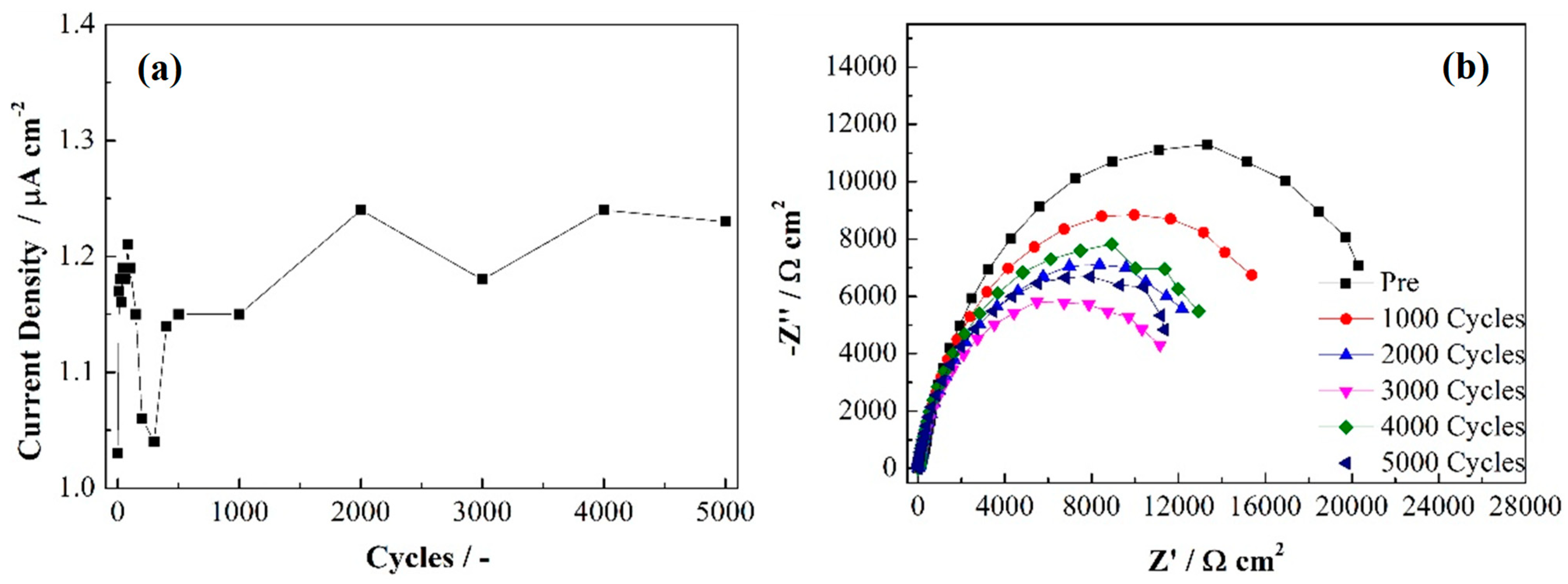
| Stage | Rs (Ω cm2) | Cdl (Ω−1 cm−2 s−n) | ndl | Rct (Ω cm2) | Cpore (Ω−1 cm−2 s−n) | npore | Rpore (Ω cm2) |
|---|---|---|---|---|---|---|---|
| pre | 1.80 | 1.01 × 10⁻⁴ | 0.9 | 2.76 × 10⁴ | 6.72 × 10⁻⁵ | 0.91 | 6.17 × 10² |
| 1000 | 1.77 | 1.56 × 10⁻⁴ | 0.92 | 2.17 × 10⁴ | 1.16 × 10⁻⁴ | 0.87 | 2.80 × 10² |
| 2000 | 1.76 | 1.75 × 10⁻⁴ | 0.92 | 1.77 × 10⁴ | 1.45 × 10⁻⁴ | 0.85 | 1.83 × 10² |
| 3000 | 1.76 | 1.81 × 10⁻⁴ | 0.93 | 1.41 × 10⁴ | 1.68 × 10⁻⁴ | 0.84 | 1.25 × 10² |
| 4000 | 1.78 | 1.38 × 10⁻⁴ | 0.93 | 1.92 × 10⁴ | 1.69 × 10⁻⁴ | 0.85 | 94.89 |
| 5000 | 1.77 | 1.45 × 10⁻⁴ | 0.93 | 1.70 × 10⁴ | 1.95 × 10⁻⁴ | 0.83 | 77.19 |
Disclaimer/Publisher’s Note: The statements, opinions and data contained in all publications are solely those of the individual author(s) and contributor(s) and not of MDPI and/or the editor(s). MDPI and/or the editor(s) disclaim responsibility for any injury to people or property resulting from any ideas, methods, instructions or products referred to in the content. |
© 2023 by the authors. Licensee MDPI, Basel, Switzerland. This article is an open access article distributed under the terms and conditions of the Creative Commons Attribution (CC BY) license (https://creativecommons.org/licenses/by/4.0/).
Share and Cite
Li, R.; Cai, Y.; Liu, Y.; Xie, Z.; Wippermann, K.; Lehnert, W. The Potential Effect on the Performance of CrN/Cr-Coated SS316L Bipolar Plates and Their Durability in Simulated Cathodic HT-PEFC Environments. Energies 2023, 16, 7528. https://doi.org/10.3390/en16227528
Li R, Cai Y, Liu Y, Xie Z, Wippermann K, Lehnert W. The Potential Effect on the Performance of CrN/Cr-Coated SS316L Bipolar Plates and Their Durability in Simulated Cathodic HT-PEFC Environments. Energies. 2023; 16(22):7528. https://doi.org/10.3390/en16227528
Chicago/Turabian StyleLi, Ruiyu, Yun Cai, Yilin Liu, Ziqi Xie, Klaus Wippermann, and Werner Lehnert. 2023. "The Potential Effect on the Performance of CrN/Cr-Coated SS316L Bipolar Plates and Their Durability in Simulated Cathodic HT-PEFC Environments" Energies 16, no. 22: 7528. https://doi.org/10.3390/en16227528
APA StyleLi, R., Cai, Y., Liu, Y., Xie, Z., Wippermann, K., & Lehnert, W. (2023). The Potential Effect on the Performance of CrN/Cr-Coated SS316L Bipolar Plates and Their Durability in Simulated Cathodic HT-PEFC Environments. Energies, 16(22), 7528. https://doi.org/10.3390/en16227528