Article

Improved Control Strategy for Water Pumping System Fed by Intermittent Renewable Source †

1
Laboratoire des Systèmes Electriques LR11ES15, ENIT, Université de Tunis El Manar, Tunis 1002, Tunisia
2
Department of Electrical Engineering, ENSIT, Université de Tunis, Tunis 1008, Tunisia
3
LAPLACE, UMR CNRS, Toulouse INP, UT3, Université de Toulouse, ENSEEIHT 2 Rue Camichel, CEDEX 07, 31071 Toulouse, France
*
Author to whom correspondence should be addressed.
This paper is an extended version of our paper published in 2013 International Workshop on Simulation for Energy, Sustainable Development & Environment Conference, Athens, Greece, 25–27 September 2013, pp. 7–11.
Energies 2023, 16(22), 7593; https://doi.org/10.3390/en16227593
Submission received: 2 October 2023 / Revised: 24 October 2023 / Accepted: 9 November 2023 / Published: 15 November 2023
(This article belongs to the Section A: Sustainable Energy)

Abstract

:
This paper focuses on a water pumping system fed by a hybrid (PV–Wind) generator. The water pumping system uses centrifugal pumps driven by variable speed Induction Motors (IM) controlled by a Field Oriented Control (FOC). The absence of battery storage to decouple sources and power demand is the main originality of the contribution, together with the typical adaptation of the FOC strategy. Furthermore, the absence of battery storage will consequently lead to fixing the system operating point at a steady state which is imposed both by the intermittent renewable energy sources and by the hydraulic load characteristics. The basic idea is then to adapt the system impedance by using the two degrees of freedom offered by the power source inverter in order to control, firstly, the DC bus voltage and, secondly, the rotor flux of the induction machine; the adaptation of the FOC strategy is based on this idea. Simulation results clearly confirmed by experimental investigations show the satisfying performance of the system even with variable powers of the intermittent renewable source.

1. Introduction

Water and electricity are vital for human beings, especially for their socio-economic development. However, given the changing demographic situation, there has been a significant increase in demand, varying from one region to another depending on the migration of people. These two shortcomings are more evident in remote areas, which are often deprived of electricity and water. The demand for freshwater is forecasted to rise significantly in the upcoming decades, creating a growing global water shortage challenge. Currently, water scarcity impacts two-thirds of the world’s population for at least one month annually [1,2]. Over the past decade, water consumption has surged sixfold, with a persistent annual growth rate of 1% [3]. In addition, obtaining fresh water in a majority of communities poses a challenge because of the high salinity levels found in both surface water and groundwater. Consequently, brackish water must undergo desalination processes before it becomes suitable for agricultural use. Moreover, water production (desalination) and pumping demand a huge level of electric energy; these two aspects are then strongly coupled. Water and energy are deeply linked in different sectors, economic activities and social measures, defined as the water–energy nexus [4]. In that context, pumping systems for irrigation or water desalination fed by intermittent renewable energy sources can be considered an adequate solution in urban and/or rural areas.
For urban areas, several works are focused on pumping systems powered by renewable energies. Most of these systems are connected to the utility grid for many advantages and reasons. When pumping is not required (full tank or low water demand) or contrarily when the water demand is huge with respect to renewable energy availability, the electric grid offers a flexible solution to decouple sources and power demand [5,6].
For remote areas, renewable energy sources with wind and/or photovoltaic generators are often used, especially inside zones where wind and solar resources are widely existent [7,8,9,10,11,12]. The complementarity of wind and solar resources coupled in “hybrid power sources” leads to minimizing the intermittence of the produced electrical power and makes it easier to supply the water pumping systems.
In that context, hybrid renewable energy sources for water pumping systems are discussed in much of the research literature in terms of architecture, modeling and control. The proposed architecture can be classified into single or double stages. In [13], a single stage is proposed which combines a boost inverter to reduce the PV voltage input. The speed reference for the outer loop is generated from a modified P&O algorithm. However, a three-phase LC filter must be added. A single-stage architecture is proposed in [14] with a PV-fed “reduced switch inverter” involving a four-switch voltage source inverter in order to reduce both switching losses and system costs. This power supply is adapted for the speed of the sensorless control of an induction machine driving a water pumping system.
In order to increase the degrees of freedom of these standalone systems, most of pumping systems use a double-stage architecture. An AC–DC–AC direct-drive power converter is presented in [10] and is implemented for a wind turbine-fed water pumping system. The authors have developed a variable “V/f” control of a single-phase pump to extract water in a wide range of power inputs and operate close to the maximum electrical power curve of the wind turbine. This control strategy has shown its limits for low hydraulic power loads. In fact, the required electric power is imposed by the load, which degrades the MPP (Maximum Power Point) of the wind turbine.
The main power load of the pumping system is the motor pump. Many types of electric motors are used to drive pumping systems. DC motors have been used first in PV pumping systems. This choice is naturally attractive, especially for the direct coupling of DC motors to PV sources. Static and transient performance have been studied in many works [15,16,17]. However, AC motor induction motors are now the most exploited machines in pumping systems, whether powered by conventional or renewable energy sources, compared with a Brushless DC Motor (BLDCM), Permanent Magnet Synchronous Motor (PMSM) and Switched Reluctance Motor (SRM) [18]. This choice is due to many advantages such as good reliability, standardization, being manufactured in large quantities and being available for a wide range of power. Several research works and architecture designs are presented for coupling induction motor pumps with renewable energy sources (mainly wind and/or solar) [19,20,21,22,23,24,25,26,27,28]. In order to operate renewable sources at their maximum power (i.e., in MPP Tracking mode), these systems have to be coupled to a voltage-controlled DC bus. In classical standalone systems, the DC bus is controlled by a battery storage device which partly decouples the intermittent power supply and the power demand related to the pumping system. In that context, a first major idea of the system proposed in this paper is “to prefer hydraulic storage to replace or at least to minimize electrochemical batteries” classically used in standalone water pumping systems fed by renewable intermittent power sources. This proposition leads to decreasing system capital and owning costs by increasing the system life cycle, given that batteries are generally the most fragile devices inside such systems.
But in the absence of battery storage, one major issue is related to the DC bus control. In classical grid-connected solutions, or for the standalone systems equipped with a storage device, the DC bus voltage is either controlled from the grid or from the storage sub system. In standalone mode, without an electric storage device, the issue is “how to control the DC bus voltage, knowing that renewable sources are power (MPPT) controlled”?
The aim of this paper is then to present a new Field Oriented Control (FOC) for a pumping system fed by intermittent renewable sources without battery storage. The structure is organized as follows: Section 2 shows the system architecture, and a steady state analysis is proposed which is useful in presenting the energy behaviour and the available degrees of freedom to be exploited for the pumping system management. Then, Section 3 proposes a control strategy to manage the water pumping system fed by intermittent renewable power sources. The simulation and experimental setup carried out to validate and test the control is finally presented with corresponding test results which emphasize both the great correspondence between the simulation and experimental results and the performance and the efficiency of this original “storageless pumping system”.

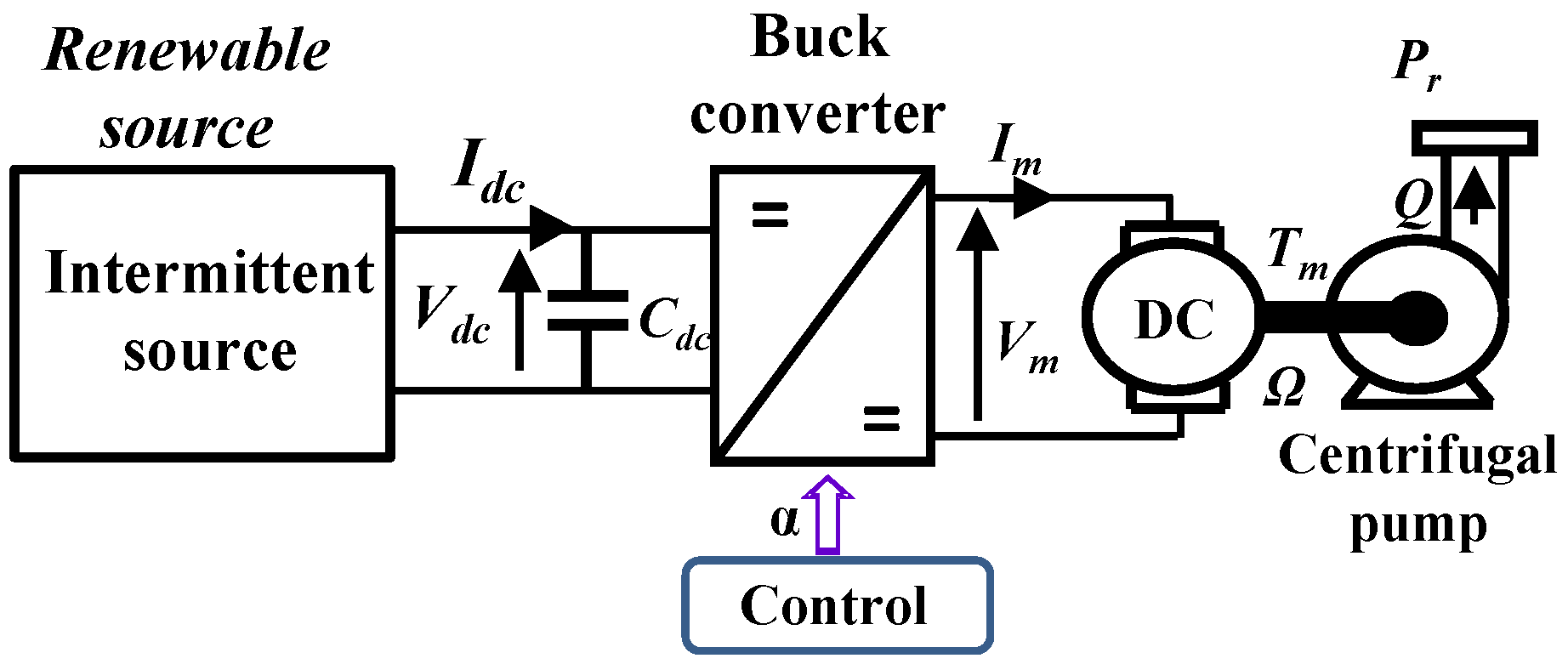
2. The “Storageless” Pumping System Structure

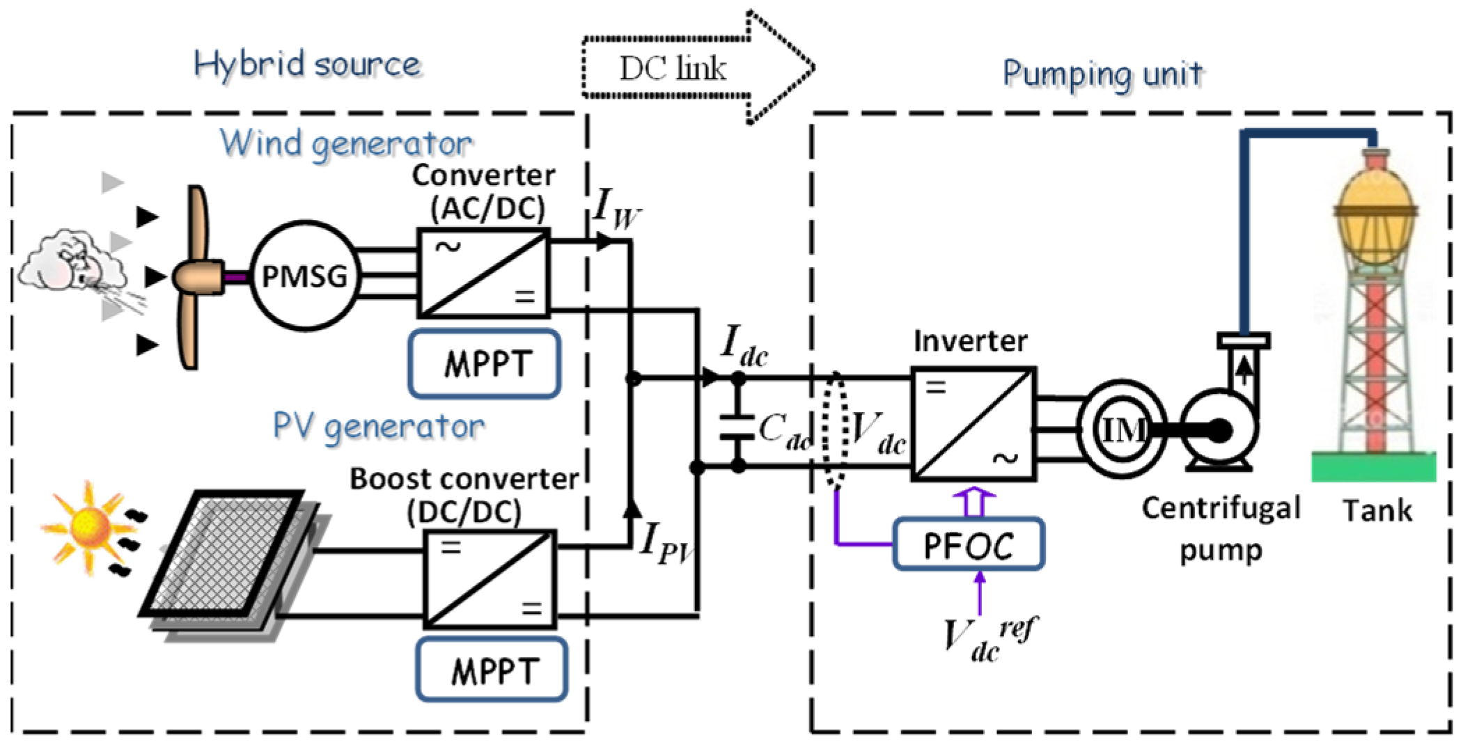
2.1. The “Hybrid Pumping System”

The “hybrid pumping system” mainly consists of coupling a hybrid source (coupling wind turbines and solar PV array) and a water pumping unit. The pumping unit can be based on a single- or a multi-motor pump. In this paper, only the single configuration is presented. The hybrid source can be powered by wind and photovoltaic generators coupled to the DC bus through static converters. The wind generator is a direct-drive technology based on a multi-pole permanent magnet synchronous generator associated with a PWM rectifier; the photovoltaic panel is connected to the DC link via a boost DC/DC chopper. To increase the energy availability, MPPT techniques are used for both sources to maximize the power transfer. Let us note that while both sources are MPPT controlled, this supposes that the pumping system is to draw this “given power from sources”. Consequently, all degrees of freedom offered by the power converters connected to renewable sources are used for their MPPT control. This principle has been presented in previous works as in [27]. In this paper, we have only considered a “given power source” directly driven by climatic (wind and solar) conditions. The pumping unit is composed of one induction motor pump driven by a voltage source inverter. This pump device, presented in Figure 1, is associated to hydraulic pipes that connect the hydraulic network for irrigation.

2.2. Steady State System Analysis

A preliminary qualitative steady state analysis of the overall system operation is first needed to understand the energy transfers in the system and its input impedance. It facilitates the conversion system understanding in order to determine the management of all Degrees of Freedom (DOF), which is really useful for the development of power management strategies. In order to make easier the qualitative steady state analysis, a simplified topology only comprising a unique centrifugal pump powered by a DC machine directly coupled to the bus via a DC–DC buck chopper is shown in Figure 2. In fact, the actual system consisting of a Field Oriented Controlled induction machine allows for decoupling the flux and the torque, which makes it quite equivalent to a DC machine for which the magnetic flux is imposed by a motor inductor while its torque is controlled by the induced current. In the same way, to simplify the analysis, losses (resistive effects) in the system are neglected in that qualitative steady state analysis.
The aim of this qualitative steady state analysis is to clarify the energy transfer between the successive physical fields crossed in this pumping system (electrical, mechanical, and hydraulic).
First, the hydraulic load characteristic (pressure Pr vs. volumic flow Q) is considered as “given” by the hydraulic network impedance. The pressure vs. flow characteristic in conventional hydraulic networks can be expressed by a quadratic impedance:
Pr = KhQ2
Second, the mechanical–hydraulic power conversion can be “simply” seen as a gyrator junction transferring mechanical variables (i.e., the torque, Tr) and the rotation speed (Ω) towards the hydraulic variables (i.e., the pressure Pr and the volumic flow Q):
Tr = KpQ
Pr = KpΩ
The simplified electromechanical equations of the DC machine are also given by a gyrator-type expression which couples the electromotive force (emf: E) with the rotor speed (Ω) and the current (Im) with the motor torque (Tm). In asteady state, if the electric losses (due to motor resistance) are neglected, the motor voltage (Vm) if close to the emf E:
Tm = Im
E = ΩVm
where the gyrator ratio () represents the flux factor of the DC machine.
Finally, the DC–DC buck chopper is controlled by a duty cycle noted “α”. If we neglect conversion losses, we can deduce the electric equations in the DC–DC converter.
Vm=αVdc
Idc=αIm
By considering the two cascaded gyrators (Equations (2)–(5)) and the buck chopper (Equations (6)–(7)) association we can derive the input output transfer equations:
V dc   = α ·   K p   ·   P r = ·   K h α ·   K p   ·   Q 2
Q = α ·   K p   ·   I d c
Thus, according to the above equations, the system impedance is derived (10):
V d c = α ·   K p 3   ·   K h   ·   I d c 2
The electric load characteristic seen from the DC bus involving the DC–DC chopper, the motor pump and the hydraulic load takes a quadratic form that depends on the duty cycle “α”, which thus constitutes the DOF for controlling this system.
However, the operation of the “storageless” pumping system with both wind and solar power strongly differs from a conventional decoupled system that operates with batteries. Indeed, for battery-based systems, the power management optimizes energy efficiency (at least when the battery is properly charged). This control mode is quite similar to the one obtained with a traditional grid-connected source with quasi “infinite” power.
Contrarily, in our “storageless” case, the electric power delivered by the hybrid renewable sources operating in MPPT mode is fully transmitted (excluding losses) through the static converter to the pump unit via the DC bus. In this particular case, the power consumption is imposed (locked) by the hybrid sources given the hydraulic load characteristic, which here is the quadratic impedance of Equation (10). In that case, the hydraulic characteristic derived in Equation (1) has a quadratic shape as illustrated in Figure 3 (right part). Thus, given the renewable source power (Pdc), the intersection between the source (blue line in Figure 3—right part) and the load characteristic (red line in Figure 3—right part) constitute the unique operating point in the hydraulic plan (i.e., the Pr,Q plan), which is locked at a single operating point imposed at the curve crossing.
At the system input (DC bus side), Figure 3—left part shows that multiple operating points are set by the intersection of the power hyperbola (Idc = Pdc/Vdc; blue curve) given by the hybrid power and the electric characteristics (red curves) that depend on the buck converter duty cycle (α) according to the Equation (10). Finally, the control DOF α will be used in our original control strategy to set and stabilize the bus voltage by adapting the electric equivalent input system impedance derived from Equation (10).
Changing the operation in the hydraulic plan leads to changing the input power (blue hyperbola) or the hydraulic load. Then, the original idea is here to exploit the DOF offered by the buck converter “α” to control the DC bus voltage while controlling the DC motor current. For that purpose, a cascaded current–voltage control can be achieved.
Based on that simplified analysis and coming back to our case study with an induction motor pump powered by a voltage source inverter, the vector control of that system is quite similar, if a little more complex by reasoning in the Park’s reference frame (d,q). Indeed, in that case, two DOFs (αd, αq) are offered by the voltage source inverter, as shown in Figure 4. Our proposition is to use the first DOF(αd) to set the magnetizing flux in the induction machine while the second one αq is “free to be exploited” in order to control the DC bus voltage which must be stabilized to authorize the MPPT mode for both renewable sources.

3. Design of the Vector Control Strategy

Basically, the classical Field Oriented Control (FOC) applied to a grid connected pumping system would regulate the flux and the speed or the torque. In the case of a “storageless” stand alone system when the pumping system power is supplied by the renewable source operated in MPPT, the produced power is imposed onto the pumping system. Consequently, given the hydraulic load characteristics it is not possible to freely regulate the motor torque or the speed. Furthermore, to ensure the good operation of the MPPT, the DC bus voltage must be as stable as possible. Thus, an improved FOC specially adapted for a standalone and storageless water pumping system is investigated in this paper, exploiting the first DOF offered by the voltage source inverter to regulate the flux along the d-axis and the second DOF to maintain and stabilize the DC bus voltage along the q-axis. The current reference in the q-axis (Isq_ref) is set following an external loop for the DC bus voltage control.
Finally, two control loops are proposed for flux and DC voltage which set both stator voltages from controllers synthesized from the following state model:
V s d = R s r I s d + σ L s d I s d d t M s r R r L r 2 φ r d ω s L s σ I s q
V s q = R s r I s q + σ L s d I s q d t + M s r ω s L r φ r d + ω s L s σ I s d
where:
R s r = R s + R r M s r L r 2
σ = 1 M s r 2 L s L r
The previous Equations (11) and (12) can be written in the following forms:
V s d = V s d 1 + E d
V s q = V s q 1 + E q
where:
V s d 1 = R s r I s d + σ L s d I s d d t
V s q 1 = R s r I s q + σ L s d I s q d t
With Ed and Eq being, respectively, the d-axis and q-axis back electromotive force (EMF), the first order transfer function of the (d,q) currents vs. voltage components can be presented as follows:
I s ( d , q ) V s 1 ( d , q ) = 1 R s r 1 + σ     L s R s r s
To control Isd and Isq currents, conventional PI controllers are used to generate appropriate signals to the PWM voltage source inverter.
The angle position is estimated using the back EMF expressed in the (d, q) reference frame from the rotor flux amplitude φ r :
E d = 1 1 + σ r d φ r d t
E q = 1 1 + σ r ω s φ r
where:
σ r = M s r L r
From (22) the stator angular frequency ωs can be determined from the emf in the q-axis:
ω s = 1 + σ r φ r E q
The rotor field position is then calculated by integrating ωs.
It can be noted the control strategy performance is strongly dependent on the angular position measure or estimator based, in our case, on the Back EMF technique. Model Reference Adaptative System (MRAS) technique can also be used for that purpose.
The rotor flux estimated using the following expression is regulated by means of a PI controller.
φ r = M s r 1 + τ r s I s d
where:
τ r = L r R r

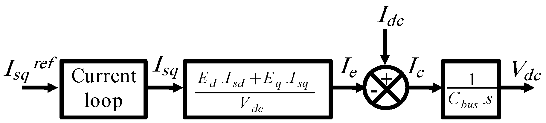
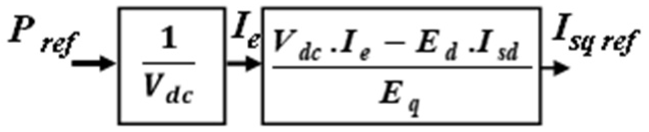
DC Voltage Bus Control

In order to couple the hybrid power source and the pumping unit, it is required to stabilize the bus voltage through a link capacitor (Cbus) between the source and the inverter. The DC bus voltage (Vdc) must be maintained constantly whatever the power transfer in the DC bus. The current balance in the DC bus is given by the following equation:
I d c = I e + I c
The basic idea in order to control the DC bus voltage is to keep the power balance at the input/output of the inverter:
V d c . I e = V s d . I s d + V s q . I s q
In a steady state and by neglecting the voltage drop due to stator resistance in the IM, Equation (27) becomes:
V d c . I e = E d . I s d + E q . I s q
The transfer model between the DC bus capacitor and the q-axis induction machine current (i.e., the “torque current”) is represented by the diagram shown in Figure 5.
From the previous equations and the block diagram and by considering that the motor current loop dynamic is faster than the bus voltage dynamic, the cascaded control structure of Figure 6 is proposed.
Figure 7 shows the block diagram of the FOC strategy applied to the voltage source inverter:
A typical application of this improved control strategy is a solar PV pumping system where the DC–DC converter can be removed. Therefore, the PV power source can directly supply the induction motor pump through the voltage source inverter. The reference of the DC voltage control loop is thoughtfully selected in order to operate the PV source in MPPT mode.
In addition, this kind of system can be easily integrated into DC microgrids where pumping system is directly power controlled depending on the energy management system. In fact, when the DC bus voltage is considered as constant in DC microgrids the external loop may be dedicated to power control, as shown in Figure 8.

4. Simulations, Experimental Setup and Validation Results

In this section, both simulation and experimental results are presented.

4.1. Simulation Results

Simulations of the proposed control strategies are conducted by using 20-sim software [29] based on bond graph modeling. The details of the modeling of different elements of the power conversion chain (from the source to the hydro mechanical load) are presented in previous works [27,28]. The DC bus capacitor is pre-charged to 250 V. In order to previously simplify the analysis, we have chosen to operate the PV generator at constant power and the wind turbine generator at variable wind to highlight the dynamic performance. In this study, the authors investigate the impact of the produced power of a hybrid wind–photovoltaic source as an intermittent power source to feed a water pumping system. Nevertheless, as wind speed fluctuations might happen more quickly than the shading effects felt by solar systems, we have chosen a variable wind and a constant irradiation for the hybrid PV–wind emulator in order to evaluate the effectiveness of the control system built. The wind model is function of time as determined by the sum of several harmonics given in Equation (29):
V w i n d = A 0 + i = 1 n a i . sin ( b i . ω v . t )
The simulation results show the dynamics and the performance of the designed control strategy. Figure 9 shows the proposed wind profile imposed on the wind turbine. The DC power (Pdc) and current (Idc), as well as the DC voltage (Vdc) controlled by the FOC strategy are depicted in Figure 10. As shown in this figure, the DC power follows the wind variations. However, the input power variation is filtered by the large inertia of the wind turbine. The DC voltage is kept constant by the FOC Controller and set to the reference (Vdcref = 300 V).
Given the hydraulic load, the electric power variations in the DC bus are transmitted to the hydraulic part of the system, as shown in Figure 11. The hydraulic power variations are smoothed due to the mechanical and hydraulic inertia. Figure 12 shows the evolution of the global efficiency according to the DC bus power variation given the hydraulic load: note that the latter is a consequence of this particular management strategy set without battery storage.
The produced power from the hybrid renewable sources is maximized thanks to both MPPT algorithms, while the motor pump efficiency depends on both the power levels derived from the sources and the hydraulic load characteristic emphasized in Figure 12. The main drawback of that “storageless topology” is that the system efficiency is a consequence of the forced operating point and can be degraded under certain conditions, especially when the source and hydraulic load characteristics are not well adapted. One solution, studied in [30], is to consider a multi-pump system which offers the capability of switching ON/OFF some of these pumps depending on the power level provided by the renewable sources. In [31] this same idea is applied to a two-pump system, a first for water pumping and a second (a high-pressure pump) for reverse osmosis desalination. A fuzzy logic-based energy management system is proposed to optimize the system efficiency regardless of the power provided by the renewable sources.
The motor magnetic flux level is controlled by the PI controller and regulated to its rated value. Thus, the power flow from the DC bus to the motor pump is controlled through the torque current that regulates Vdc.

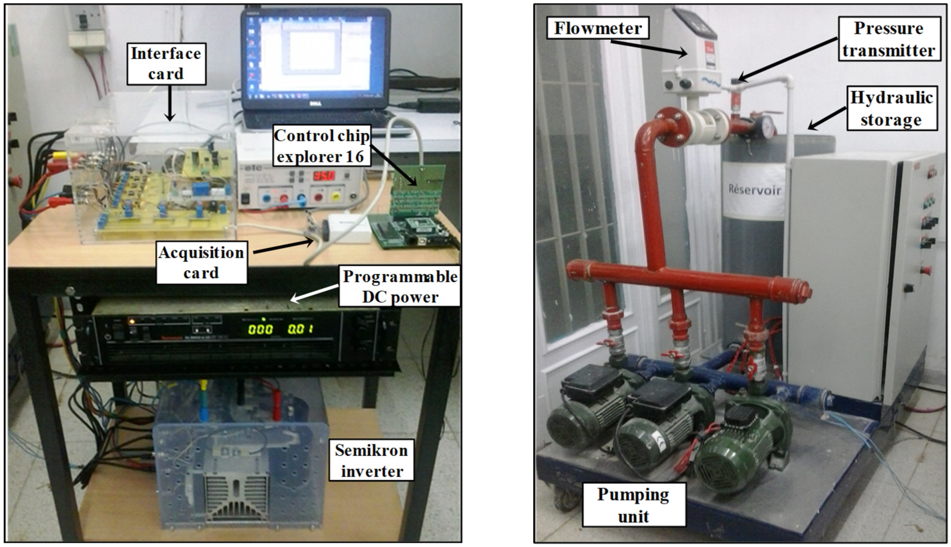
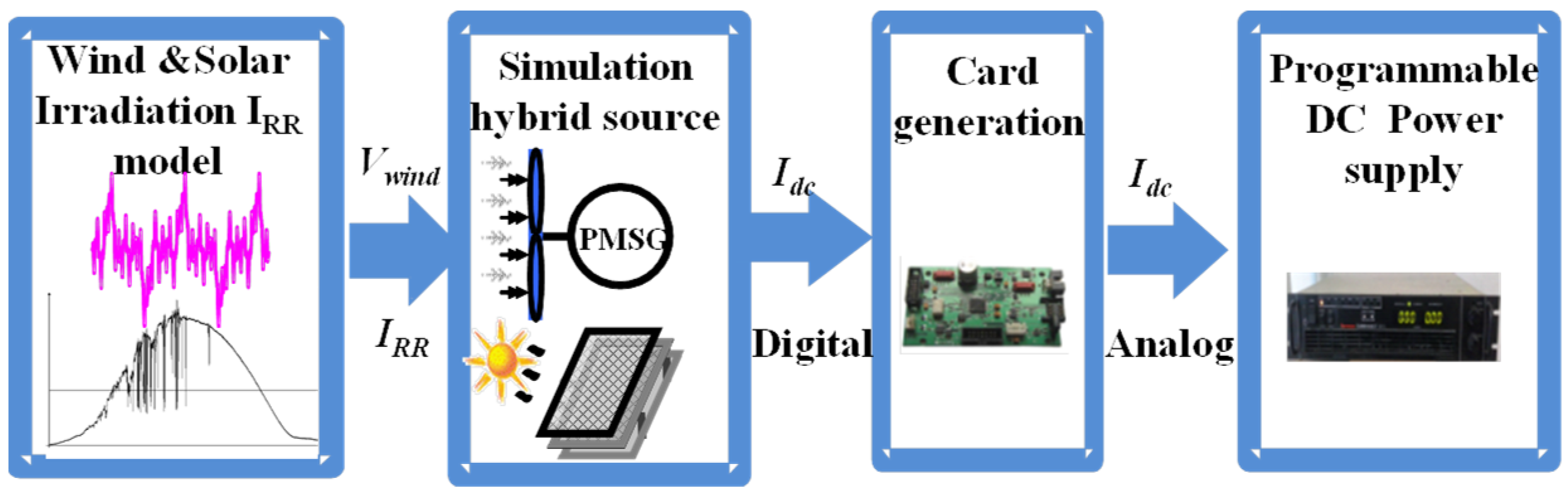
4.2. Experimental Setup

The experimental setup shown in Figure 13 and Figure 14 is composed of a programmable DC power source (DLM 4 kW from Sorensen) that emulates the hybrid renewable power sources. It also integrates a voltage source inverter (Semikron 20 kVA), a three-phase centrifugal motor pump (DAB 750 W) whose parameters are shown in Appendix A, a Dspic microcontroller which encloses the FOC, and an electronic card generating the DC current reference [30].
The target control board for the digital implementation of the FOC is an “explorer 16” board from a microchip. Three Hall Effect current sensors (LEM LTS-25nP) are used to measure two stator currents of the induction motor and DC bus current produced by the programmable power supply. One Hall Effect voltage sensor (LEM LV-25P) is used to measure the DC bus voltage. An acquisition card NI-DAQ 6008 from national instruments is used to measure and save data on the DC bus current, DC bus voltage, hydraulic pressure and water flow.
The proposed control strategy was implemented using a digital control system based on a DSPic 33FJ256MC710 microcontroller. This microcontroller has a high-performance 16-bit central processing unit (40 MIPS) and peripherals that are particularly suitable for motor control applications.
Four analog quantities acquisition has been implemented by using the internal analog–digital (A/D) converter, two stator currents of the induction machine, DC bus current (Idc) and DC bus voltage (Vdc).
The interruption of the A/D converter is executed every 62.5 μs and is triggered every PWM period (the switching frequency of the PWM is set at 16 kHz). The conversion result is transferred and stored in DMA buffer (direct memory access). The synchronization of the different control blocks is made through the interrupt mechanism. It generates the instants and the order execution of the various modules. This order must take into account the speed of the internal and external loops of the FOC.
The current (Isd, Isq) loop bandwidth is chosen at 5 kHz. The DC voltage loop bandwidth is chosen as 500 Hz.

4.3. Experimental Results and Discussions

The wind profile of Figure 9 is tested by a simulation on a 1 kW wind turbine generator with the architecture presented in Figure 1. The PV generator power is considered as constant. From this simulation, the variable DC current Idc is converted in digital data format to emulate the intermittent source behavior by setting it as an input to the control card. In this way, the adequate analog reference Idc is generated to the programmable power supply.
The current profile will be active only if the power supply operates as a current source. From this device, the operation of a wind turbine submitted to variable wind and constant PV produced power coupled to the DC bus is then emulated. The emulation process from experimental device is presented in Figure 15.
Initially, before starting the FOC software, the programmable power supply works as a voltage source. The source voltage and current limits are also initialized.
The voltage provided by the programmable source is set to an initial value of 320 V. At the initial instant t = 0 s, the FOC program is started: in this case, only the rotor flux and the current torque “Isq” are controlled. At the instant t1 = 52 s, as displayed in Figure 15, the DC voltage external loop regulation is started and set to a reference of 300 V (bus voltage-controlled mode). The power supply is then switched to a controlled current mode. The generated current profile is here constant and equal to 1.5 A. Both the bus voltage and the torque current converge to their references. Thus, the motor pump is also controlled at a constant power.
From the dedicated card, the generation profile is started from t2 = 135 s involving variable powers which emulate the wind turbine operation.
The electrical and hydraulic variables are stored on a time horizon of 600 s (10 min) to fully assess the test cycle.
Figure 16 shows the good performance of the DC bus voltage control Vdc from the FOC strategy for variable DC power. Note that from t1 to 600 s, the DC power Pdc varies according to the reference generated by the card generation. From t2, the programmable power supply operates as a hybrid renewable source emulator. The power produced is then variable.
Figure 17 confirms that, given the hydraulic load, the pressure and flow variables follow the variations of the DC bus power Pdc. It can be remarked that the experimental transient behavior is fully in accordance with the corresponding simulation results presented in Figure 10, which validates both the theoretical vision in terms of power management and the transient model of the water pumping unit used in the FOC strategy. Some slight differences can be observed on the volumic flow variations (Q) between simulations of Figure 10 and experiments of Figure 17, but these shapes are qualitatively in good agreement. The same remark can be made on the system efficiency, which is very close, by comparing the simulation of Figure 12 with the global system efficiency obtained from the experiments and shown in Figure 17. The derivation of the experimental efficiency is obtained from the ratio between the hydraulic vs. the DC bus powers.
In this particular case, given the input power range and the hydraulic load characteristics, the system efficiency is slightly variable and remains constantly correct when the DC bus power Pdc is varied due to the variable winds. Figure 18, in which the simulation of Figure 12 is repeated, allows us to emphasize the accordance between simulation and experimental results, giving confidence to the system modelling.

5. Conclusions

An original “storageless stand-alone pumping structure” has been proposed which consists of removing the battery storage “preferring storing water than ions in an electrochemical storage”. This original proposition aims to avoid battery costs for both investment and operation (battery replacements due to ageing). However, as analyzed in Section 2, removing the storage device imposes the operating point of the pumping system given the source power itself imposed by the environment (solar and wind) conditions and given the hydraulic characteristics. The system efficiency is then a consequence of this “imposed operating point”. Adding a storage device allows the decoupling of the source and hydraulic network and managing the pumping system operating point and its efficiency. Thus, a techno-economic trade-off must be performed, which constitutes a major prospect of that study.
In order to support this typical storageless structure, an adaptation of the classical FOC has been proposed for the pumping unit involving a voltage source inverter feeding an induction motor. Based on the two degrees of freedom offered by the voltage source inverter supplying the motor pump, the FOC is adapted from classical vector control principles: the motor currents are controlled in the Park’s reference frame (d,q) oriented along the rotor flux for the classical rotor field-oriented control. As for the classical FOC, the first degree of freedom is used for the regulation of the rotor flux according to the d-axis. However, the control on the q-axis is far from being classical: the hydraulic operating point being locked at the intersection of the power provided by the renewable sources and the hydraulic load impedance, the second degree of freedom on the q-axis is exploited to achieve the regulation of the DC bus voltage. A cascaded bus voltage/current control structure is added, setting the q-axis current in an inner control loop. Stabilizing the DC bus control from the field-oriented controlled pump unit allows operating both renewable (PV and wind) sources in MPPT mode.
This typical FOC has been tested by simulation and implemented experimentally. Solar PV and wind turbine operation at variable power has been emulated from a programmable DC power source. Simulation analyses are confirmed by experimental results, demonstrating the validity of the theoretical assessments and the control strategy. The global performance of the pumping system is very close between the simulations and experiments and proves the relevance of this particular “storageless structure”.
It should also be pointed out that the system efficiency performance of this particular structure (without decoupling between power production and load demand) can be degraded following the adaptation quality of the hydraulic load with the input power range. Indeed, it has been shown in previous works [27] that the global efficiency strongly depends on the hydraulic load characteristics and also on the level of the input power. This is a typical consequence of this original “storageless standalone pumping structure”. As a solution, it has been shown in [27,31] that exploiting system modularity should be relevant by using several pumps which would operate sequentially according to the input power range with better efficiencies. Consequently, for this typical pumping system as presented in Figure 1, using N motor pumps will increase the number of DOFs, one DOF would be dedicated to the DC bus voltage regulation of the first motor pump, while the (N-1) remaining DOFs may be exploited to optimize the power management of the overall system. A typical application of the modularity in offline optimization is presented in [28]. One challenge in future works is to search for optimized online power management strategies. This idea was proposed through fuzzy control in [32] and will be compared with neural or MPC strategies in current and future works.

Author Contributions

Conceptualization, A.B.R.; methodology, X.R.; formal analysis, X.R. and B.S.; investigation, A.B.R.; resources, J.B.; writing—original draft preparation, A.B.R.; writing—review and editing, X.R., B.S. and J.B.; supervision, J.B.; project administration, X.R. and J.B. All authors have read and agreed to the published version of the manuscript.

Funding

The APC was funded by the PHC-Utique project “23G1124”.

Data Availability Statement

Data are contained within the article.

Acknowledgments

This work was supported by the Tunisian Ministry of Higher Education and Research under Grant LSE–ENIT-LR 11 ES15.

Conflicts of Interest

The authors declare no conflict of interest.

Nomenclature

RsStator resistance
RrRotor resistance
LsStator inductance
LrRotor inductance
MsrMutual inductance
RsrStator rotor equivalent resistance
ωsStator angular frequency
σBlondel coefficient
Vsd, VsqStator voltage components in dq reference frame
Isd, IsqStator current components in dq reference frame
Ed, Eqback electromotive force (EMF) components in dq reference frame
ϕr, ϕrd, ϕrqRotor flux vector and its components in dq reference frame
τrRotor time constant
IdcDC current in the DC bus
IeInverter DC input current
IcCurrent in DC bus capacitor
VdcDC bus voltage

Appendix A

Table A1. Induction motor parameters.
SpecificationParameters
Power750 WRs7.5 Ω
Voltage230 VRr11 Ω
Current4.3 ALs0.484 H
Frequency50 HzLr0.484 H
Pole pairs1Msr0.46 H
Speed2980 rpmRsr17.436 Ω
σ0.0967

References

  1. Khondoker, M.; Mandal, S.; Gurav, R.; Hwang, S. Freshwater Shortage, Salinity Increase, and Global Food Production: A Need for Sustainable Irrigation Water Desalination—A Scoping Review. Earth 2023, 4, 223–240. [Google Scholar] [CrossRef]
  2. Mekonnen, M.M.; Hoekstra, A.Y. Sustainability: Four billion people facing severe water scarcity. Sci. Adv. 2016, 2, e1500323. [Google Scholar] [CrossRef]
  3. Wada, Y.; Flörke, M.; Hanasaki, N.; Eisner, S.; Fischer, G.; Tramberend, S.; Satoh, Y.; Van Vliet, M.T.H.; Yillia, P.; Ringler, C.J.G.M.D.; et al. Modeling global water use for the 21st century: The Water Futures and Solutions (WFaS) initiative and its approaches. Geosci. Model Dev. 2016, 9, 175–222. [Google Scholar] [CrossRef]
  4. Wang, X.C.; Jiang, P.; Yang, L.; Van Fan, Y.; Klemeš, J.J.; Wang, Y. Extended water-energy nexus contribution to environmentally-related sustainable development goals. Renew. Sustain. Energy Rev. 2021, 150, 111485. [Google Scholar] [CrossRef]
  5. Vamja, R.V.; Mulla, M.A. Development of grid-interactive inverter utilising induction motor driven photovoltaic water pumping system. IET Power Electron. 2020, 13, 3373–3383. [Google Scholar] [CrossRef]
  6. Abidi, M.; Ben Rhouma, A.; Belhadj, J. Water-Energy system toward the meeting of an improved Low Voltage Ride Through Capability of Grid-Connected photovoltaic generator: Power-sharing and control issues. Energy Sources Part A Recovery Util. Environ. Eff. 2020, 1–28. [Google Scholar] [CrossRef]
  7. Liu, B.; Zhou, B.; Yang, D.; Li, G.; Cao, J.; Bu, S.; Littler, T. Optimal planning of hybrid renewable energy system considering virtual energy storage of desalination plant based on mixed-integer NSGA-III. Desalination 2022, 521, 115382. [Google Scholar] [CrossRef]
  8. Zaibi, M.; Cherif, H.; Champenois, G.; Sareni, B.; Roboam, X.; Belhadj, J. Sizing methodology based on design of experiments for freshwater and electricity production from multi-source renewable energy systems. Desalination 2018, 446, 94–103. [Google Scholar] [CrossRef]
  9. Vick, B.D.; Neal, B.A. Analysis of off-grid hybrid wind turbine/solar PV water pumping systems. Sol. Energy 2012, 86, 1197–1207. [Google Scholar] [CrossRef]
  10. Lara, D.D.; Merino, G.G.; Pavez, B.J.; Tapia, J.A. Efficiency assessment of a wind pumping system. Energy Convers. Manag. 2011, 52, 795–803. [Google Scholar] [CrossRef]
  11. Sadasivam, P.; Kumaravel, M.; Vasudevan, K.; Jhunjhunwala, A. Analysis of subsystems behaviour and performance evaluation of solar photovoltaic powered water pumping system. In Proceedings of the 2013 IEEE 39th Photovoltaic Specialists Conference (PVSC), Tampa, FL, USA, 16–21 June 2013; pp. 2932–2937. [Google Scholar] [CrossRef]
  12. Dali, M.; Belhadj, J.; Roboam, X. Hybrid solar–wind system with battery storage operating in grid-connected and standalone mode: Control and energy management—Experimental investigation. Energy 2010, 35, 2587–2595. [Google Scholar] [CrossRef]
  13. Prabhakaran, K.K.; Sunkara, V.; Karthikeyan, A. Single-stage PV-powered boost inverter-fed permanent-magnet synchronous motor-driven water-pumping system. Clean Energy 2022, 6, 726–737. [Google Scholar] [CrossRef]
  14. Narendra, A.; Venkataramana, N.N.; Panda, A.K.; Tiwary, N.; Kumar, A. A Single-Stage SPV-Fed Reduced Switching Inverter-Based Sensorless Speed Control of IM for Water Pumping Applications. Int. Trans. Electr. Energy Syst. 2022, 2022, 3805791. [Google Scholar] [CrossRef]
  15. Firatoglu, Z.A.; Yesilata, B. New approaches on the optimization of directly coupled PV pumping systems. Sol. Energy 2004, 77, 81–93. [Google Scholar] [CrossRef]
  16. Kolhe, M.; Joshi, J.C.; Kothari, D.P. Performance Analysis of a Directly Coupled Photovoltaic Water-Pumping System. IEEE Trans. Energy Convers. 2004, 19, 613–618. [Google Scholar] [CrossRef]
  17. Mokeddem, A.; Midoun, A.; Kadri, D.; Hiadsi, S.; Raja, I.A. Performance of a directly-coupled PV water pumping system. Energy Convers. Manag. 2011, 52, 3089–3095. [Google Scholar] [CrossRef]
  18. Angadi, S.; Yaragatti, U.R.; Suresh, Y.; Raju, A.B. Comprehensive review on solar, wind and hybrid wind-PV water pumping systems—An electrical engineering perspective. CPSS Trans. Power Electron. Appl. 2021, 6, 1–19. [Google Scholar] [CrossRef]
  19. Errouha, M.; Derouich, A.; Nahid-Mobarakeh, B.; Motahhir, S.; El Ghzizal, A. Improvement control of photovoltaic based water pumping system without energy storage. Solar Energy 2019, 190, 319–328. [Google Scholar] [CrossRef]
  20. Shukla, S.; Singh, B. MPPT control technique for solar powered direct torque control of induction motor drive with a robust speed and parameters adaptation scheme for water pumping. IET Renew. Power Gener. 2018, 13, 273–284. [Google Scholar] [CrossRef]
  21. Singh, B.; Sharma, U.; Kumar, S. Standalone Photovoltaic Water Pumping System Using Induction Motor Drive with Reduced Sensors. IEEE Trans. Ind. Appl. 2018, 54, 3645–3655. [Google Scholar] [CrossRef]
  22. Mudlapur, A.; Ramana, V.V.; Damodaran, R.V.; Balasubramanian, V.; Mishra, S. Effect of Partial Shading on PV Fed Induction Motor Water Pumping Systems. IEEE Trans. Energy Convers. 2019, 34, 530–539. [Google Scholar] [CrossRef]
  23. Shukla, S.; Singh, B. Reduced Current Sensor Based Solar PV Fed Motion Sensorless Induction Motor Drive for Water Pumping. IEEE Trans. Ind. Inform. 2019, 15, 3973–3986. [Google Scholar] [CrossRef]
  24. Muljadi, E.; Nix, G.; Bialasiewicz, J.T. Analysis of the dynamics of a wind-turbine water-pumping system. IEEE Trans. Power Eng. Soc. Summer Meet. 2000, 4, 2506–2519. [Google Scholar] [CrossRef]
  25. Bialasiewicz, J.T.; Muljadi, E. Power transfer and time-domain analysis of a wind-turbine water-pumping system. IEEE Trans. Ind. Appl. 2003, 2, 1302–1307. [Google Scholar] [CrossRef]
  26. Miranda, M.S.; Lyra, R.O.; Silva, S.R. An alternative isolated wind electric pumping system using induction machines. IEEE Trans. Energy Convers. 1999, 14, 1611–1616. [Google Scholar] [CrossRef]
  27. Rhouma, A.B.; Belhadj, J.; Roboam, X. A pumping system fed by hybrid photovoltaic-wind sources without battery storage Bond graph modeling, control and energy management. In Proceedings of the IMAACA 2010: The 4th International Conference on Integrated Modeling and Analysis in Applied Control and Automation, Fès, Morocco, 13–15 October 2010; pp. 67–72. [Google Scholar]
  28. Abidi, M.; Rhouma, A.B.; Belhadj, J. Optimal coordinated planning of water-energy system-based MILP algorithm of a multi-pump PV water station by deeming power commitment. Electr. Power Syst. Res. 2023, 220, 109343. [Google Scholar] [CrossRef]
  29. Software for Modeling Complex Physics. Available online: https://www.20sim.com/ (accessed on 1 August 2023).
  30. Rhouma, A.B.; Belhadj, J.; Robaom, X. Theoretical and experimental investigation for “storage less” control of a water pumping system fed by intermittent renewable sources. In Proceedings of the 1st International Workshop on Simulation for Energy, Sustainable Development and Environment, SESDE 2013, Athens, Greece, 25–27 September 2013; pp. 7–11. [Google Scholar]
  31. Rhouma, A.B.; Belhadj, J.; Roboam, X. Energy management and control strategy for water pumping system fed by intermittent renewable sources. In Proceedings of the 12th International Conference on Modeling and Simulation of Electric Machines, Converters and Systems (ELECTRIMACS’2017), Toulouse, France, 4–6 July 2017. [Google Scholar]
  32. Ali, I.B.; Turki, M.; Belhadj, J.; Roboam, X. Fuzzy Logic for Solving Water-Energy Management Problem in Standalone Water Desalination System: Water-Energy Nexus and Fuzzy System Design. Int. J. Fuzzy Syst. Appl. 2023, 12, 1–28. [Google Scholar] [CrossRef]
Figure 1. The proposed pumping system.
Energies 16 07593 g001
Figure 2. Schematic diagram of a simplified pumping system with DC motor.
Energies 16 07593 g002
Figure 3. Electric and hydraulic operating point(s) given the input power sources and given the load impedance.
Energies 16 07593 g003
Figure 4. “Cooperative inter domain” energy management with control of the DC bus voltage and flux by the inverter.
Energies 16 07593 g004
Figure 5. Block diagram of the DC bus vs the torque current.
Energies 16 07593 g005
Figure 6. DC bus voltage control loop.
Energies 16 07593 g006
Figure 7. Block diagram of the FOC strategy.
Energies 16 07593 g007
Figure 8. Block diagram of the DC bus power control loop.
Energies 16 07593 g008
Figure 9. Wind speed profile.
Energies 16 07593 g009
Figure 10. Input power, current and voltage in the DC bus.
Energies 16 07593 g010
Figure 11. Hydraulic power, pressure and water flow according to DC power variations.
Energies 16 07593 g011
Figure 12. Global efficiency variations.
Energies 16 07593 g012
Figure 13. The experimental water pumping system without battery storage.
Energies 16 07593 g013
Figure 14. The experimental test bench for the water pumping system.
Energies 16 07593 g014
Figure 15. Experimental physical emulation of the hybrid renewable power source.
Energies 16 07593 g015
Figure 16. Input power, current and voltage in the DC bus.
Energies 16 07593 g016
Figure 17. Hydraulic power, pressure and water flow according to DC power variations.
Energies 16 07593 g017
Figure 18. Global efficiency variation. Left, for experiments; right, for simulation results.
Energies 16 07593 g018
Disclaimer/Publisher’s Note: The statements, opinions and data contained in all publications are solely those of the individual author(s) and contributor(s) and not of MDPI and/or the editor(s). MDPI and/or the editor(s) disclaim responsibility for any injury to people or property resulting from any ideas, methods, instructions or products referred to in the content.

