Article

Analysis of the Wireless Power Transfer System Using a Finite Grid of Planar Circular Coils

by
Jacek Maciej Stankiewicz
Faculty of Electrical Engineering, Bialystok University of Technology, Wiejska 45D, 15-351 Bialystok, Poland
Energies 2023, 16(22), 7651; https://doi.org/10.3390/en16227651
Submission received: 15 October 2023 / Revised: 13 November 2023 / Accepted: 16 November 2023 / Published: 19 November 2023
(This article belongs to the Special Issue Advanced Technology in Wireless Power Transfer and Harvesting Systems)

Abstract

:
In this paper was analysed a wireless power transfer system (WPT) with multiple resonators supplying, for example, sensors or LED lighting. Energy is transferred simultaneously using a group of identical planar spiral circular coils acting as transmitters and receivers. These coils were arranged to form transmitting and receiving planes. The receivers were connected to independent power supply circuits of each, e.g., sensor or LED lighting. Higher power reliability and flexibility can be achieved by isolating these circuits. The proposed system was described and discussed. Taking into account the skin effect and mutual couplings, a theoretical analysis was made. A detailed analysis was made at the resonant frequency of the system. The system was modeled using a matrix equation and appropriate formulas. The calculations were verified experimentally for different loads and two distances between transmitters and receivers. The efficiency and receiver power were compared and discussed. The maximum efficiency was about 45% at the small distance between the planes. The maximum efficiency of the WPT system decreased more than two times to less than 20% when the distance between the coils was doubled. The results and discussion of the conducted analysis may provide valuable knowledge when designing this type of system.

1. Introduction

Electricity generated in a conventional power plant is very expensive, and the overall transmission efficiency from the power plant to the end user can be very low (about 30%), in particular due to energy losses in parasitic resistances. A power plant running on coal, gas or nuclear fuel requires many resources to produce electricity and faces many environmental problems (e.g., pollution). Additionally, insufficient compensation of reactive power, voltage asymmetry, and current distortions reduce the efficiency and quality of electricity transmitted to consumers [1].
Charging a device using cables is very lossy, difficult to install and often ends in failure. The number of portable devices is growing, but wired chargers prevent these devices from being fully portable. Taking the above into account, alternative solutions for charging devices, mainly home ones, were sought. The solution to eliminate the indicated problems is Wireless Power Transfer (WPT) technology [2]. The WPT system can efficiently transfer energy from the source to the device using the phenomenon of electromagnetic induction. The advantage of this system is the mobility of the devices and the lack of radiation.
Wireless power transfer (WPT) systems are used in, for example, electric vehicles (EVs) [2,3,4,5], data transmission [6], and consumer electronics [7,8]. WPT technology has also found its application in medical devices [9,10], robotic systems [11], and buildings equipped with sensors [12]. In the publications [13,14], various shapes of coils and the influence of their geometry on the system efficiency are analysed. These factors have a major influence on the quality of the transmission. In the articles [15,16], the authors analysed laser cut and printed textile coils. The authors showed that the resistance of the coil affects the efficiency. Wire diameter and number of turns can decrease or increase system efficiency. An important factor in the analyzed WPT systems is the skin effect [17]. In the article [18], the authors showed that if the coil thickness was the same as the skin depth, it would reduce the losses due to the skin effect. Data transmission is greatly influenced by the environment in which the wireless system is located. The electrical parameters of the materials from which the wireless system is made are also important [16,19,20].
The effective operation of the WPT system is the main design challenge. The work [21] presents a method for designing a high-performance WPT system. Limitations on receiver coil size are included. The optimal pitch of the transmitter and receiver coils was calculated by analyzing the coil quality factor. Equations are provided that give an approximate design sketch for the transducer size. The authors focused on examining the influence of variability in the dimensions of the transmitting coil on the efficiency of the system.
WPT technology has a very wide range of applications in mobile solutions, i.e., electric vehicles or consumer electronics. These solutions mainly use a single coil rather than the periodic array that is considered in this article. The authors of [22] focused on reducing the coil resistance, which translates into higher efficiency with the lowest possible weight. In [23,24], in order to reduce the influence of the internal resistance of the source and at the same time improve the efficiency of this system, a source coil was added, creating a three-coil structure. The results show that with a higher internal resistance of the source, increasing the system efficiency is only possible by adding a source coil. This is only possible with larger coils.
Numerical methods (e.g., FEM, FDTD, FDFD) [24,25] allow the creation of a complex model and the determination of the magnetic field distribution. In this typical approach, it is necessary to prepare a 3D model and impose appropriate boundary conditions. However, the efficiency and accuracy of the solution depend on the size of the model (number of degrees of freedom, NDOF). Increasing NDOF will result in higher solution accuracy but also longer computation time. In the article [26], one of the solutions related to the wireless charging system was proposed. The discussed system contains periodically arranged planar circular or square coils. The maximum efficiency and maximum load power in the proposed periodic WPT system were solved based on exemplary structures with multiple magnetic couplings between inductive elements. Models were developed to solve the proposed structures consisting of many circular or square planar coils. The use of a circuit model, represented by a single cell of the WPT system, eliminated the need to create very complicated models that are solved using numerical methods. This article also presented the construction of a 3D numerical model and conditions that allow reducing the complexity of the numerical model.
Losses in the coils were analysed using the FEM (Finite Elements Method) numerical method. The results showed that the more conductive material increased weight and efficiency. In the case of WPT systems, however, we are dealing with optimal efficiency, but the authors only took into account the Litz wire. Therefore, these conclusions are not practical for WPT systems with coils made of wires. The authors of [27] analysed the influence of the coil size and the number of turns on the efficiency of the WPT system. The research concerned only Litz wire and the influence of the substrate on the coil resistance. The analysis concerned WPT systems used in electric vehicles, which use larger coils.
The authors of many publications mainly considered coil–coil systems. Solutions of this type are mainly used for charging electric vehicles. This article proposes another solution (series–parallel) that allows you to charge multiple devices or one. This functionality is possible thanks to the use of flat planar coils. The topology of the system and the phenomena occurring between the coils of the transmitting and receiving planes as well as the relationships between adjacent coils affect the parameters of the WPT system. The author of [28] showed a mixed series–parallel topology. This solution makes the transmission distance larger than in the case of series topology. The efficiency is higher than in parallel topology. However, the authors of [29] showed a series–parallel–series topology. The indicated solution allows for obtaining sufficient power in the event of significant misalignment. The authors of [30] showed various types of array coils, e.g., domino. The analysis was made only for the series configuration. Based on the available literature, it was noticed that a series–parallel system with planar coils has not been analysed so far.
Although WPT technology has many applications, the increasing power transmission distance often results in a decrease in transmission efficiency, as well as an urgent need to address safety concerns. Metamaterials offer a way to improve efficiency and reduce flux density in WPT systems [31,32]. The authors of [31] present an overview of the status and technological challenges facing metamaterial-based WPT systems. The paper reviews a metamaterial-based wireless energy transmission system from three perspectives: transmission efficiency, misalignment tolerance, and electromagnetic shielding.
This article describes the power supply system for low-power devices. This solution applies to receivers such as sensors, LED lighting, wearable electronics, etc. A power supply method based on multiple resonators was proposed. Then, the energy is transferred simultaneously and independently to the target devices. This solution increases the reliability of the power supply and the operation of receiving devices by using its own WPT system and galvanic separation of individual circuits from each receiver. For this reason, the occurrence of damage, short circuit, or overvoltage of the resonators, or connecting cables of one of the receivers, will not have a significant impact on the functionality of the others. The proposed multi-coil system with more than one load requires a preliminary analysis of its electrical parameters, such as power and efficiency.
There are four sections in this paper. The methodology is presented in Section 2, which includes the concept of the proposed WPT system in Section 2.1, the equivalent electrical circuit in Section 2.2, and finally the experimental study for verification of theoretical research in Section 2.3. A comparison and discussion of the results, obtained during the analysis, is presented in Section 3. In Section 4, the summary is presented, and the most important conclusions are discussed.

2. Methodology

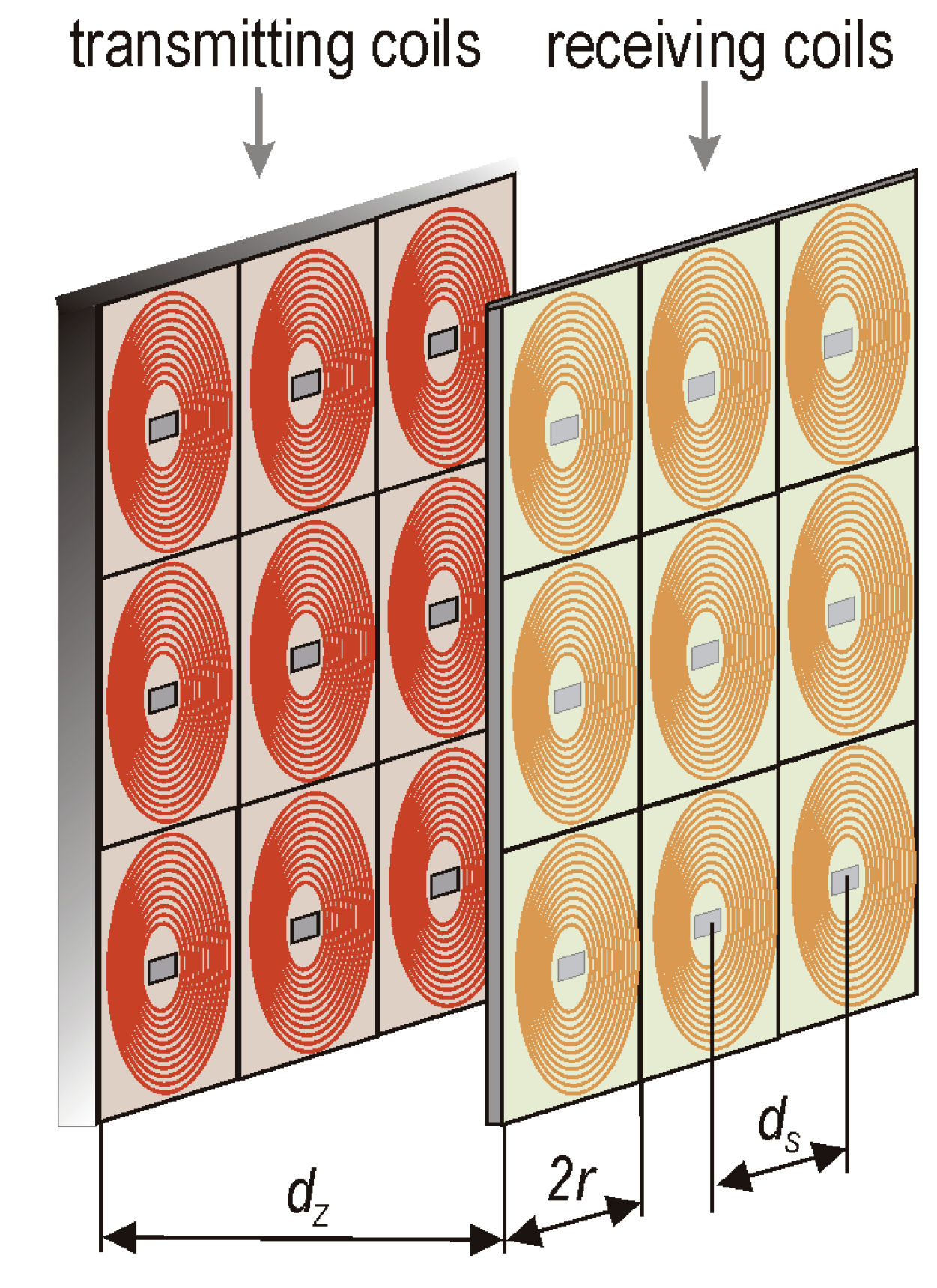
2.1. System Description

The presented WPT system has two planes: transmitting (Tx) and receiving (Rx). Eighteen coils were used to create these planes, and each plane contained nine coils (Figure 1). They were identical to simplify analysis. Each of them had a self-inductance (Lc), a coil resistance (Rco), and a lumped capacitor (Ccp). The receiver can be modeled as an equivalent resistance (R). The transmitters were connected in parallel, while the receivers were isolated from each other. The dimensions of the coil were 2r × 2r. Each coil has the same radius (r) and number of turns (nt). The distance between the planes was (dz). The distance between the centers of adjacent coils was (ds). The coils were wound on a non-conductive carcass. Each coil has a compensation capacitor connected in series with the coil to achieve a resonance state. The Tx coils were created as the transmitting plane and the Rx coils as the receiving plane. Wireless energy transfer took place between these planes. Each Tx coil was connected in parallel to the power source (Uz). Each Rx coil directly powered its load. Therefore, many receivers can be powered at the same time.
The results obtained from the experimental study were compared with those obtained from the circuit model. The parameters used in the experiment and calculations are presented below in Table 1 and Table 2.
Results from the experimental study are presented as solid blue lines (marked as Experimental results in the legend). Results from the circuit model are presented as solid red lines (marked as Analytical results in the legend).

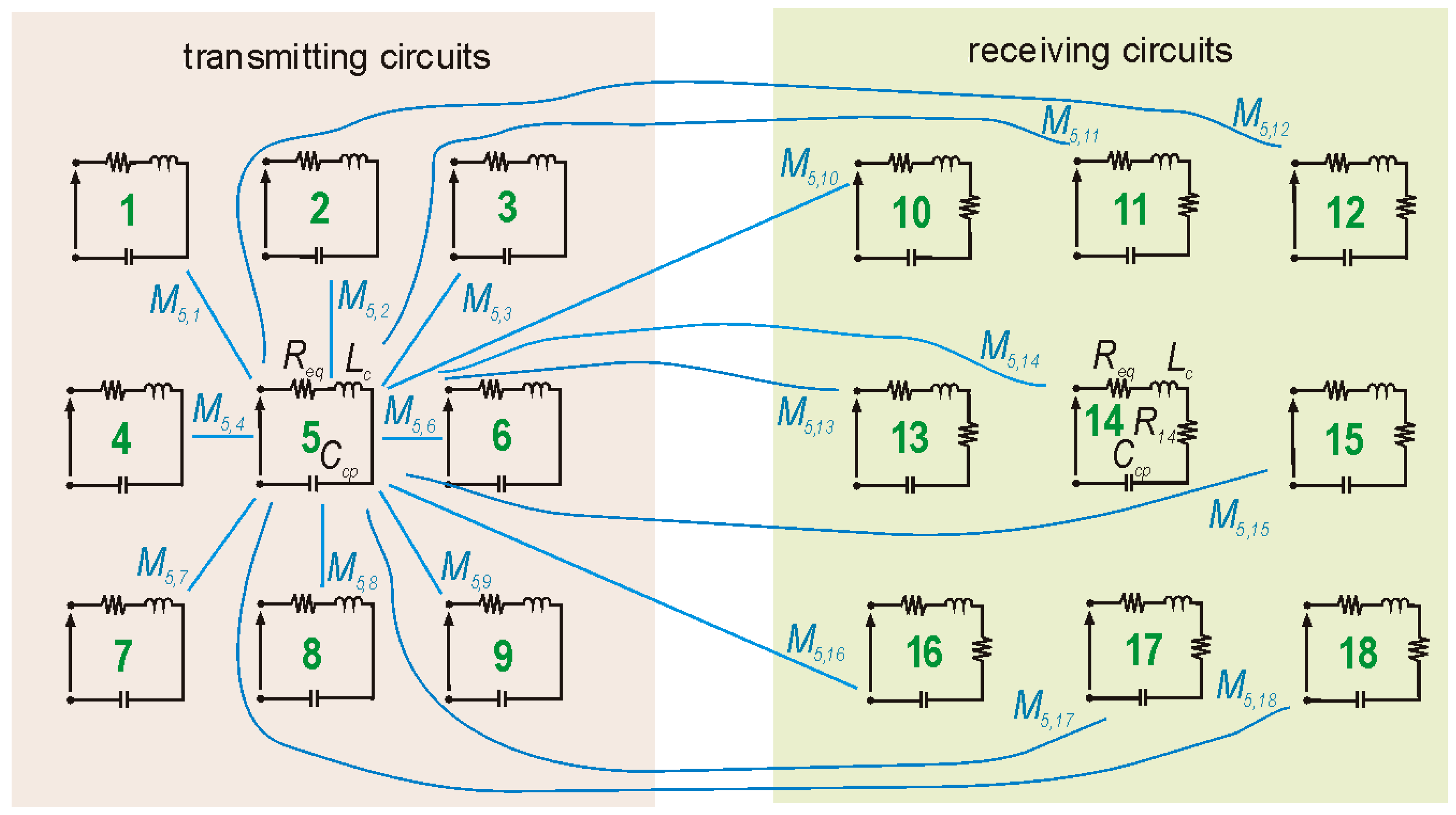
2.2. Equivalent Circuit

The WPT system was created from two square planes (Figure 1). Each plane consisted of nine coils (resonators). Each coil was wound with a wire with a diameter wc and an insulation thickness wi. The radius of the coil was r and the number of turns nt. Numbers 1 to 9 were assigned to the transmitting plane (circuits), while numbers 10 to 18 were assigned to the receiving plane (circuits). The transmitting coils (Tx) were connected in parallel to the power source Uz, the internal resistance of which was Rz. This caused an equal voltage drop Uin at the input terminals of each resonator. The receiving coils (Rx) directly powered loads R10R18. The Tx and Rx sides were magnetically coupled. Energy transfer occurred not only between two vertically directed coils, but also occurred horizontally and diagonally, i.e., between any coil and the other 17 coils. The electrical equivalent circuit of this system is presented in Figure 2. The transmitting and receiving planes with magnetic couplings are presented, where each coil was magnetically coupled with the other coil through the mutual inductance Ma,b. In order to not confuse the drawing, the magnetic couplings for coil number five were marked. For the remaining coils, the magnetic couplings will be identical.
The mutual inductance (Ma,b) of an arbitrary coil and any planar coil (a and b were the numbers of these coils, respectively) was presented below [33]:
M a , b = μ 0 s 2 4 π Φ i Φ o Φ i Φ o 1 + φ 1 φ 2 cos φ 2 φ 1 φ 2 φ 1 sin φ 2 φ 1 d z 2 + d x + s φ 2 cos φ 2 s φ 1 cos φ 1 2 + d y + s φ 2 sin φ 2 s φ 1 sin φ 1 2 d φ 1   d φ 2 ,
where s = (wc + wi)/(2π) in [m] is the screw pitch; Φi = [r − (wc + wi)nt]/s is the starting angle of the spiral; Φo = r/s is the ending angle of the spiral; φ1, φ2—is the angles of rotation along the edge of the spiral. Moreover, dz is the vertical distance between coils a and b [m]; dx, dy are the horizontal distances between coils a and b along the x and y axis [m]. All mutual inductances transfer power from the source to the receivers and, as a result, generate redundant transmission paths, even in the case of the Tx coil failure. The above equation can be solved numerically by using summation instead of double integral and dividing the angles into discrete steps:
M a , b = μ 0 s 2 Φ N 2 4 π n 2 = Φ s N + Φ s   n 1 = Φ s N + Φ s 1 + n 2 n 1 Φ N 2 cos n 2 Φ N n 1 Φ N n 2 Φ N n 1 Φ N sin n 2 Φ N n 1 Φ N d z 2 + d x + s n 2 Φ N cos n 2 Φ N s n 1 Φ N cos n 1 Φ N 2 + d y + s n 2 Φ N sin n 2 Φ N s n 1 Φ N sin n 1 Φ N 2 ,
where ΦN = (Φo − Φi)/N is the discrete step; Φs = ΦiN is the starting step; N is the number of subintervals; N > 2(r/s). With a higher number of N, the accuracy of Equation (2) tends to be the exact solution for Equation (1).
Equation (2) can be used to find the self-inductance (Lc) of the coil, because it can be interpreted as the mutual inductance of the considered inductor and itself. To calculate Lc, substitute dz = dx = dy = 0 and simplify the final formula to the equation:
L c = μ 0 s Φ N 4 π n 2 = Φ s N + Φ s   n 1 = Φ s N + Φ s 1 + n 2 n 1 Φ N 2 cos n 2 Φ N n 1 Φ N Φ N n 2 n 1 sin n 2 Φ N n 1 Φ N n 1 2 + n 2 2 2 n 1 n 2 cos n 1 Φ N n 2 Φ N .
For identical resonators, Lc has to be calculated only once, unlike Ma,b, which has to be calculated for all pairs of coils in the system. When the self-inductance is known, the capacitance (Ccp) of the compensation capacitor at the assumed desired frequency fc can be calculated below:
C c p = 1 4 π 2 f c 2 L c .
In real applications, the compensation capacitor has its own internal resistance. This equivalent series resistance (ESR) can be calculated from equation [34]:
R E S R = D F 2 π   f   C c p ,
where DF is the dissipation factor; f is the current frequency [Hz].
The resistance of the coil (Rco) will be calculated. Then, the length (lco) of the spiral has to be calculated. The formula for the finite length straight conductor was found by multiplying the average coil circumference by the number of turns (nt):
l c o = 2 π   n t r n t 1   w c + w i 2 .
Therefore, the resistance of the coil is given below:
R c o = l c o σ w a e f f = 2 π   n t r n t 1   w c + w i 2 σ w a e f f ,
where σw is the electrical conductivity of the wire [S/m]; aeff is the effective cross-section of the wire [m2]. A skin effect occurs in a high-frequency electromagnetic field; therefore, the effective cross-section of the wire is presented below [35]:
a e f f = π   δ e f f w c   δ e f f ,
where δeff is the effective skin depth [m], and it is given below:
δ e f f = 1 π   f   σ w μ 0 2 1 exp w c 2 π   f   σ w μ 0 1 / 2   .
The equivalent resistance of the resonator [Ω] is presented below:
R e q = k R R E S R + R c o ,
where kR is the coefficient responsible for the undesirable increase in resistance in real applications. The resulting equivalent resistance Req > (RESR + Rco) is due to the appearance of contact and solder resistance, impedance of the connecting wires, temperature rise in the presence of a positive temperature coefficient, capacitor leakage resistance, other parasitic resistances in the system (e.g., solder pads and printed copper paths), etc.
To calculate the currents in each resonator, lumped parameters must be calculated from Equations (2)–(5), (7), and (10) at the desired frequency fc. The simplest system of equations to solve is obtained from Kirchhoff’s voltage law:
Z ¯ I ¯ a + j ω b = 1 B M a , b I ¯ b = U i n , b , a B 2 , a b Z ¯ I ¯ a + j ω b = 1 B M a , b I ¯ b + R a = 0 , b , a > B 2 , a b ,
where Z is the impedance of the resonator; Z = Req + jωLc + 1/jωCcp [Ω]; Ia is the current in a-th resonator [A]; B is the number of all resonators. The matrix equation A·I = U, where A is the impedance matrix, can be calculated from Equation (11) for B resonators and different loads:
Z ¯ j ω M 1 , 2 j ω M 1 , B / 2 j ω M 1 , B / 2 + 1 j ω M 1 , B / 2 + 2 j ω M 1 , B j ω M B / 2 , 1 j ω M B / 2 , 2 Z ¯ j ω M B / 2 , B / 2 + 1 j ω M B / 2 , B / 2 + 2 j ω M B / 2 , B j ω M B / 2 + 1 , 1 j ω M B / 2 + 1 , 2 j ω M B / 2 + 1 , B / 2 Z ¯ + R B / 2 + 1 j ω M B / 2 + 1 , B / 2 + 2 j ω M B / 2 + 1 , B j ω M B , 1 j ω M B , 2 j ω M B , B / 2 j ω M B , B / 2 + 1 j ω M B , B / 2 + 2 Z ¯ + R B I ¯ 1 I ¯ B / 2 I ¯ B / 2 + 1 I ¯ B = U i n U i n 0 0 ,
Then, the unknown vector of currents (I = A−1·U) will be calculated. Equation (12) allows for a multi-parameter analysis of the designed system, e.g., for various coils, compensation capacitors, and loads. Finally, the efficiency of the WPT system is given below:
η = P o P z 100 % = n = B / 2 + 1 B U n 2 R n U i n   I z cos φ 100 % = n = B / 2 + 1 B R n I ¯ n 2 U i n   n = 1 B / 2 I ¯ n cos φ 100 %
where Po is the output active power (sum of real powers of loads) [W]; Pz is the input active power (sum of real powers at the input terminals) [W]; In is the complex current of the n-th resonator [A]; Iz is the RMS source current [A]; Un is the RMS voltage of the n-th load [V]; Rn is the resistance of the n-th load [Ω]; cosφ is the power factor.

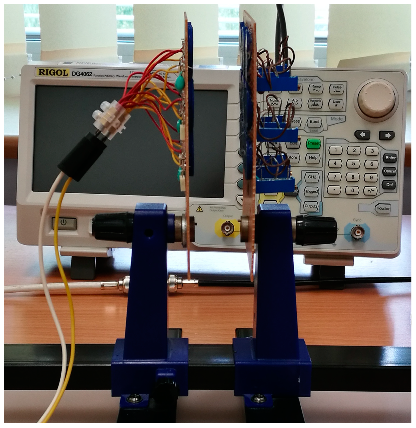
2.3. Experimental Study

The experimental study allowed for the verification of the model presented in Section 2.2. Therefore, an experimental stand was created. The coil carcasses were made of a non-conductive filament using a 3D printer. Then, 18 identical coils were created (circular planar coils were wound). Their self-inductance and resistance were measured. The compensation capacitor was then selected separately for each coil to obtain one desired resonant frequency fc using Equation (4). The coils were then connected to the capacitors on the PCB. Variable resistors were used as energy receivers (RB/2 + 1 ÷ RB). This helped to smoothly adjust the load resistances and examine their influence on the powers and efficiency of the WPT system. At the small distance between the planes, the influence of load resistance on the results was tested up to 200 Ω and at the large distance between the planes up to 70 Ω. Then, transmitting and receiving planes were made, each containing nine identical coils (resonators). The experimental stand is presented in Figure 3.
In the measurements, two planes were mounted on a gripper placed on a horizontal slide. This made it possible to adjust the distance between them. The transmitting plane was connected to a Rigol DG4062 (Beijing, China) signal generator, and then both planes were connected to an oscilloscope. A signal generator was used as a source (Uz = 20 p − pV, Rz = 50 Ω). Probes connected to a Rigol DS2072 (Beijing, China) oscilloscope were used to measure voltages and currents. The measured values were Uin (RMS input voltage), Iz (RMS source current), and UB/2 + 1 ÷ UB (RMS load voltage). All these measured values were saved on the oscilloscope in separate files for each analyzed case. Then, the efficiency and powers were calculated (Equation (13)).
During measurements, measurement errors related to the method or device may occur. The accuracy of the measurements was certainly influenced by the accuracy of the coil winding. A total of 18 coils were made, which consisted of the transmitting and receiving surfaces. The accuracy of the coil manufacturing influenced the coil’s self-inductance as well as their mutual inductances. In order to obtain the resonance state, a compensation capacitor had to be selected separately for each coil. The capacitors were selected with a tolerance of no more than 0.1 nF. For these reasons, it is difficult to obtain a resonance state for each coil at the same frequency. Measuring probes were used for measurements. The electronic components of the tested system were assembled on a PCB, which introduces losses (including solder pads and copper tracks). Additionally, near the coils, there are various metal elements used to build the experimental stand, i.e., wires, screws, mountings, the rail on which the measuring system moves, etc. All this introduces resistances and parasitic capacitances that affect the analyzed system, disturbing the measurements.

3. Discussion of the Results

The results obtained from the experimental study were compared with those obtained from the circuit model (Equation (12)). The parameters used in both analyses are presented in Table 1 and Table 2. The circuit model was solved in Matlab R2013b (MathWorks, Natick, MA, USA). Calculations were made for N = 1000 subintervals. In the numerical considerations, it was necessary to determine one self-inductance and B(B − 1)/2 = 153 mutual inductances. The mutual inductances (Ma,b) were calculated numerically from Equation (2) and the self-inductance of the coils from Equation (3). Eleven mutual inductances were estimated due to the internal and external symmetry of the transmitting and receiving planes. This resulted in a significant reduction in computation time.
At the design frequency, the influence of the load resistance (R) on the efficiency (η) and powers of the WPT system was examined. To adjust the load resistance and examine its influence on efficiency and powers, variable resistors connected to the receiving coils as energy receivers were used. Analytical and experimental results (efficiency, receiver, and transmitter powers) are presented in Section 3.1. Results from the experimental study are presented as solid blue lines (marked as Experimental results in the legend). Results from the circuit model are presented as solid red lines (marked as Analytical results in the legend).
The lumped parameters of the circuit model were calculated using Matlab R2013b software and obtained Lc = 13.84 μH, Rco = 753 mΩ, and Ccp = 7.32 nF, which gave fc = 500 kHz. The average measured parameters of the coils and capacitors used in the experiment (Lc, Rco and Ccp) were, respectively, 14.99 μH, 866 mΩ, and 6.80 nF, which gave a resonant frequency equal to almost 499 kHz. Therefore, the obtained frequency differed by only 1 kHz. Each coil used in the experimental stand had a different self-inductance because it was handmade. In practice, the resonance point may vary slightly for each resonator. This therefore required the use of appropriate capacitors to obtain the desired resonant frequency. In real applications, it is also difficult to use coils with identical parameters because the coils are made with a certain accuracy. Additionally, each coil must be attached to the PCB with additional pins, which increases its self-inductance and resistance. Therefore, it is very important to make all coils as precisely as possible. Capacitors selected for individual coils should therefore be selected with the greatest possible precision.

3.1. Results

It should be crucial to analyse the system in order to find the resonance point and determine the optimal load resistance (i.e., maximum efficiency or receiver power). The influence of load resistance on the efficiency and powers of the WPT system was analysed. The calculation and measurement results were obtained at the resonant frequency, at the distance dz = 5 mm (Section 3.1.1) and dz = 10 mm (Section 3.1.2). In the experimental study, the resonant frequency at the distance dz = 5 mm was 576 kHz and 550 kHz at the distance dz = 10 mm, while the design frequency was 500 kHz.

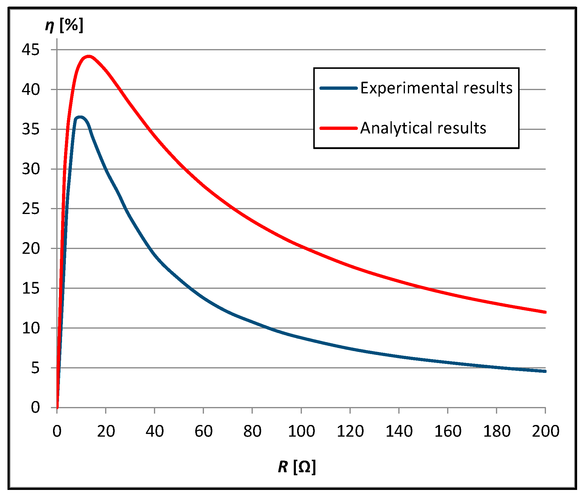
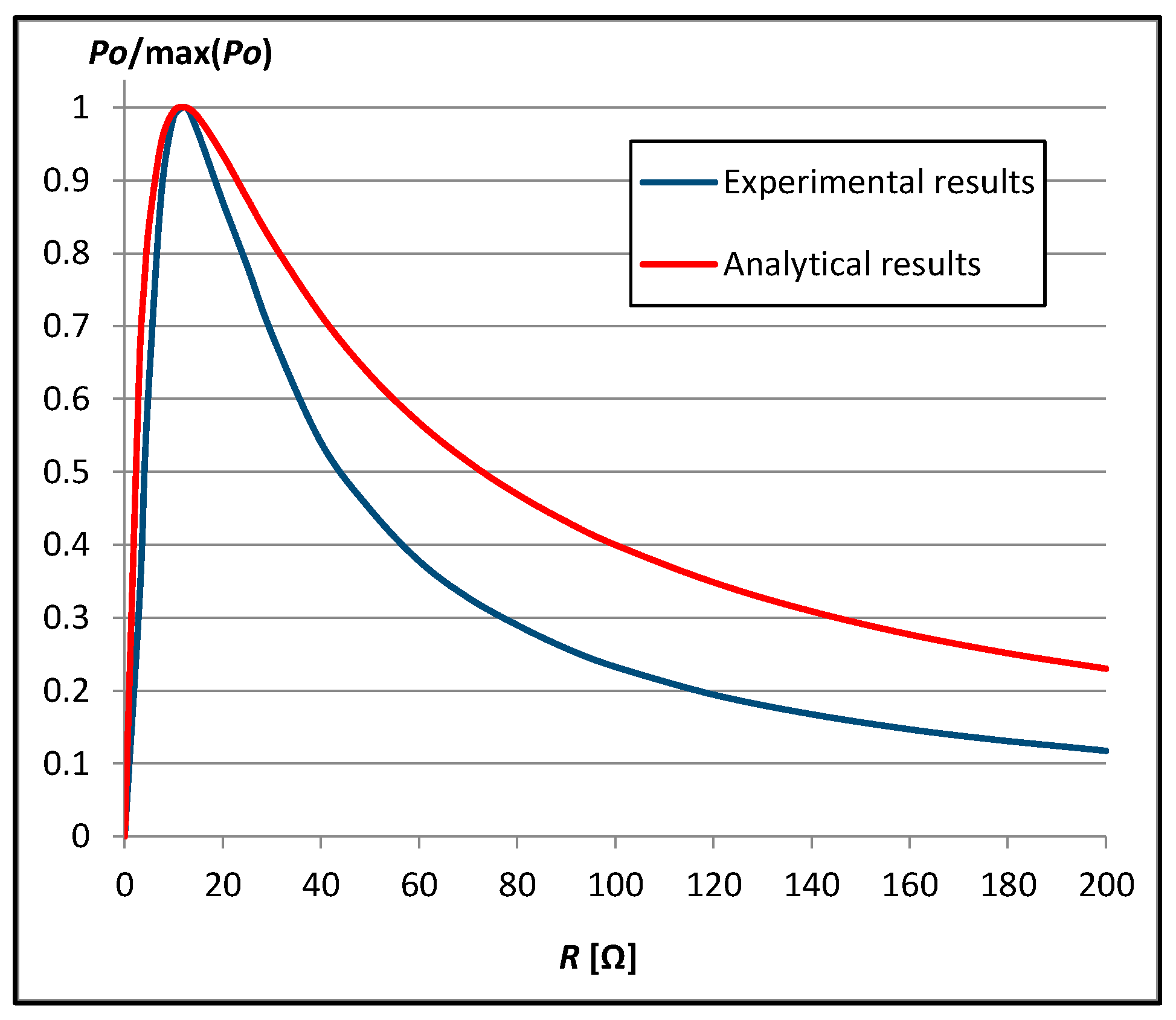
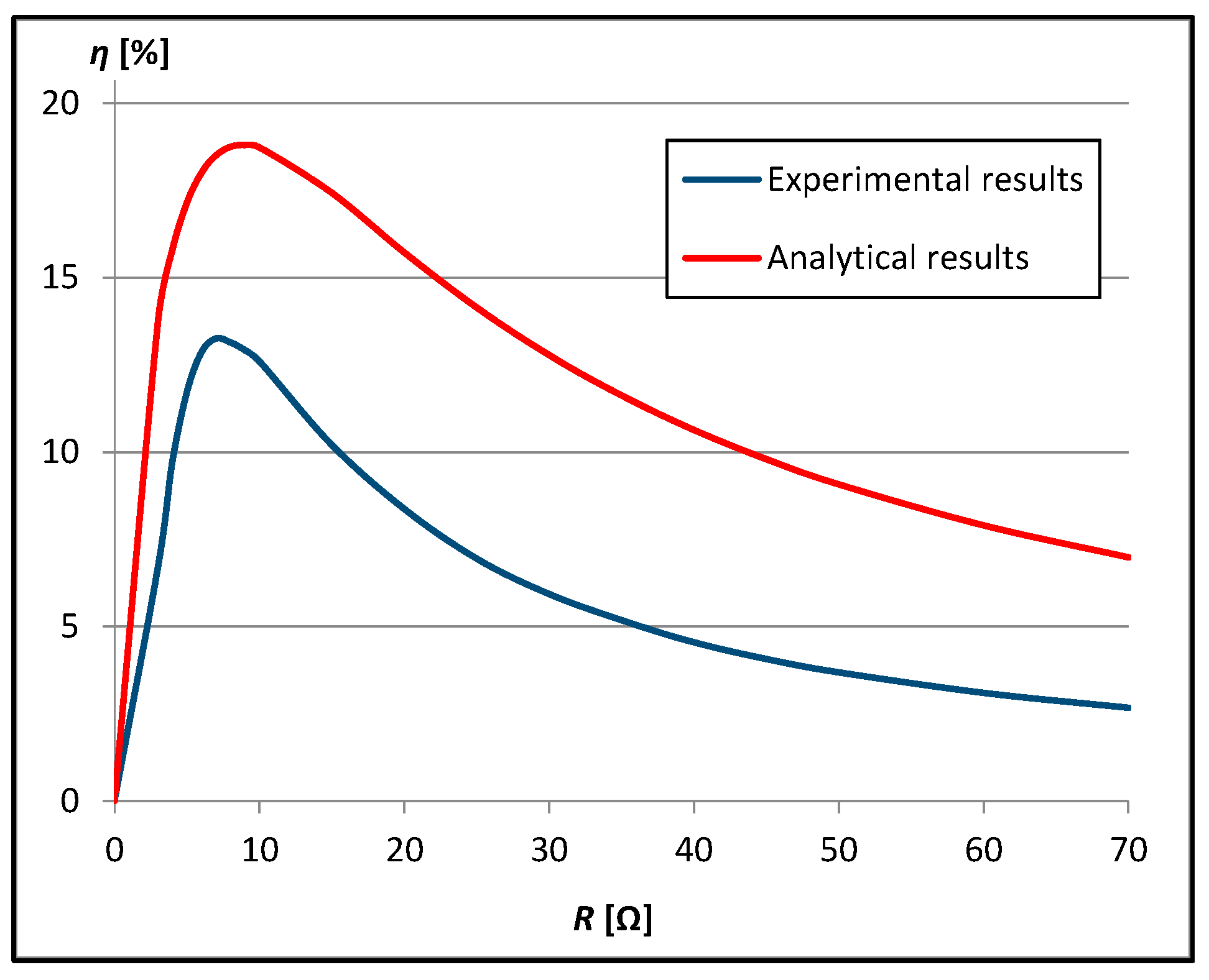
3.1.1. Results at the Distance dz = r/2 = 5 mm

Efficiency, transmitter, and receiver powers diagrams are presented in Figure 4, Figure 5 and Figure 6.
The efficiency of the WPT system increased with the increase in load resistance, and then after reaching the maximum, it began to decrease (Figure 4). The maximum efficiency obtained from calculations was 44.13% with R = 12.5 Ω and from measurements 36.83% with R = 9 Ω. With low load resistance, the efficiency of the system obtained from calculations and measurements was comparable. Additionally, with low load resistance, the efficiency increased very quickly until it reached the maximum value. The greatest difference in efficiency obtained from calculations and measurements was approximately 15% with R = 40 Ω. This difference decreases as the load resistance increases and does not exceed 8% with R = 200 Ω. However, the smallest difference in efficiency was approximately 5% with R = 7.5 Ω. The shape of the characteristics obtained from calculations and measurements was maintained.
The active transmitter (Pz) and active receiver (Po) powers varied depending on the load resistance (Figure 5 and Figure 6). The theoretical analysis of the multi-resonator WPT system was complex due to its multi-coupling nature, in which finding analytically the optimal load resistance (maximizing the efficiency or the receiver power) was significantly difficult. In order to determine the variability of the receiver and transmitter powers depending on the load resistance, characteristics from measurements and calculations were presented. The dependence of the receiver power on the load resistance (Figure 5) was almost identical to that in terms of efficiency (Figure 4). The receiver power increased as the load resistance increased and then began to decrease after reaching the maximum. The maximum receiver power was obtained with the same load resistance in the experimental study and the circuit model (12.5 Ω). The smallest difference in the receiver power, obtained from calculations and measurements, occurred with a load resistance below 12.5 Ω. The greatest difference in the receiver power, obtained from calculations and measurements, occurred for R = 70 Ω. This difference decreases as the load resistance increases. The transmitter power increased as the load resistance increased, and then after reaching the maximum, it began to decrease (Figure 6). As the load resistance increased, the transmitter power decrease was relatively small, and the results obtained from calculations and measurements differed slightly. The maximum transmitter power obtained from calculations was obtained with a lower load resistance than that obtained from measurements.

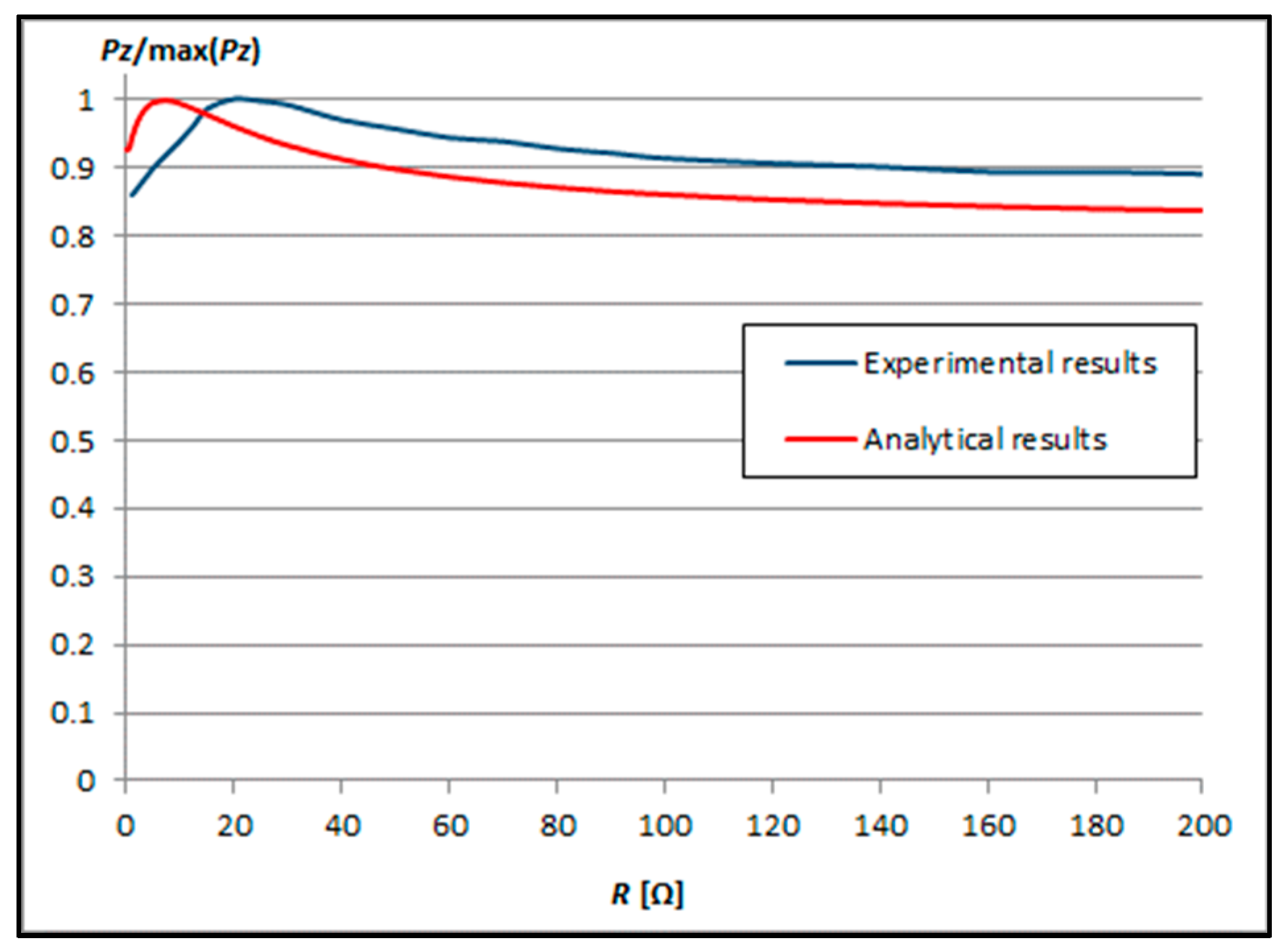
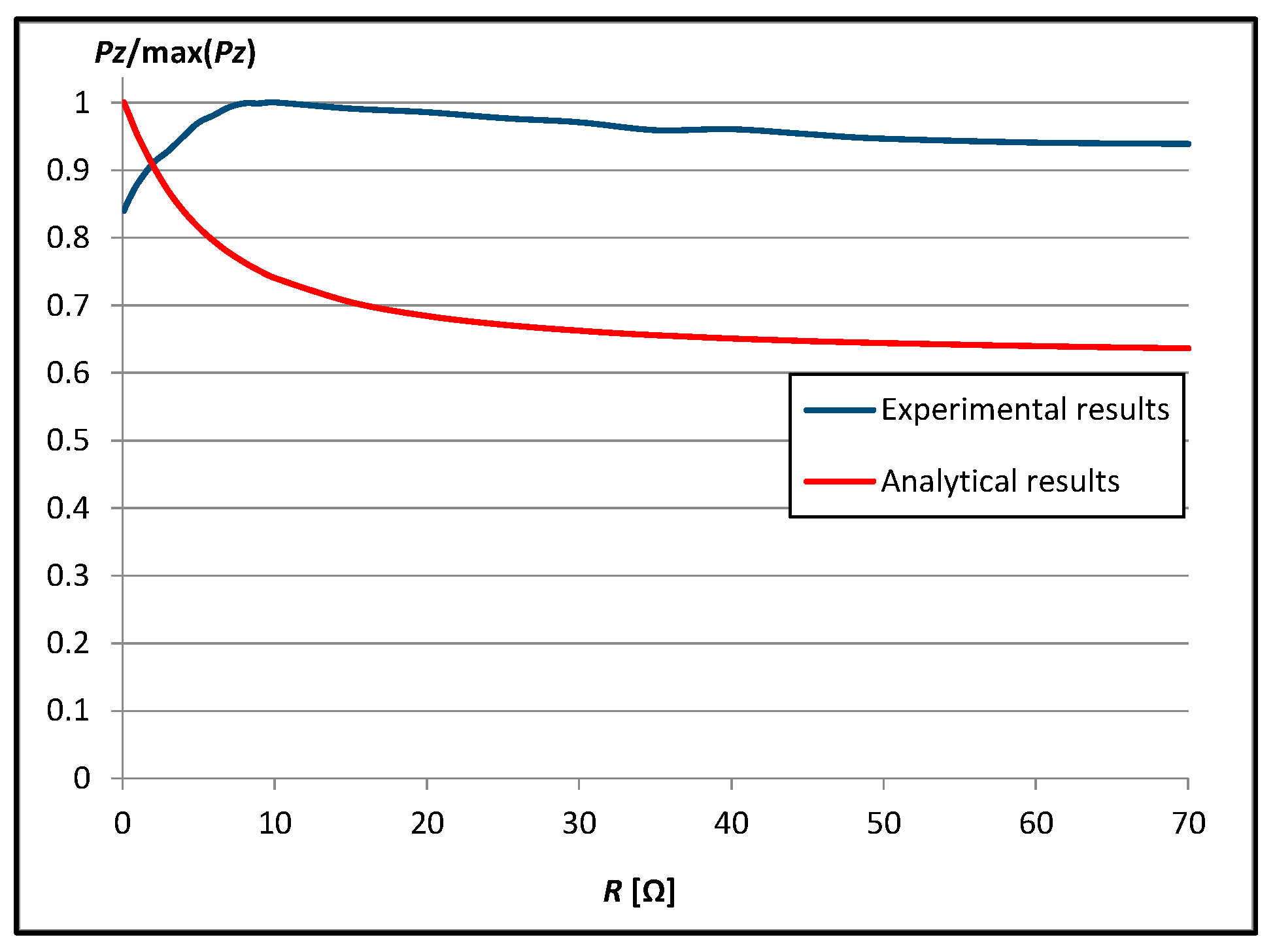
3.1.2. Results at the Distance dz = r = 10 mm

Efficiency, transmitter, and receiver powers diagrams are presented in Figure 7, Figure 8 and Figure 9.
The maximum efficiency of the WPT system decreased more than two times to less than 20% when the distance between the coils (dz) was doubled (Figure 7). The maximum efficiency obtained from calculations was 18.80% with R = 9 Ω and from measurements 13.25% with R = 7 Ω. The distance between the transmitting and receiving coils influenced the matched load resistance. The larger the distance between them, the lower the load resistance. The efficiency increased as the load resistance increased and then began to decrease after reaching the maximum. With low load resistance, efficiency increased very quickly. Then, the efficiency obtained from calculations was much higher than from measurements. The greatest difference in efficiency obtained from calculations and measurements was less than 8% with R = 20 Ω. This difference decreases as the load resistance increases and slightly exceeds 4% with R = 70 Ω. The shape of the characteristics obtained from calculations and measurements was maintained.
The receiver and transmitter powers varied depending on the load resistance (Figure 8 and Figure 9). In order to determine the variability of the receiver and transmitter powers along with the load resistance, characteristics from measurements and calculations were presented. The receiver power increased as the load resistance increased and then began to decrease after reaching the maximum. The maximum receiver power was obtained with the same load resistance in the experimental study and the circuit model (7 Ω). The smallest difference in the receiver power, obtained from calculations and measurements, occurred with a load resistance of about 7 Ω. The greatest difference in the receiver power, obtained from calculations and measurements, occurred for R = 3–4 Ω. This difference decreases as the load resistance increases. Then, after exceeding the maximum receiver power, this difference begins to increase again. The transmitter power obtained from the measurements increased with the increase in load resistance (about 9 Ω), and then, after reaching the maximum, it began to decrease (Figure 9). Then, as the load resistance increased, the transmitter power decrease was relatively small. The transmitter power obtained from the calculations decreases as the load resistance increases. As the load resistance increased, the transmitter power obtained from calculations and measurements changed more and more.
In all analyzed cases and for small and large distances between planes, theoretical calculations adequately predicted these relationships and can be helpful in determining the power, efficiency, and optimal load resistance already at the system design stage.

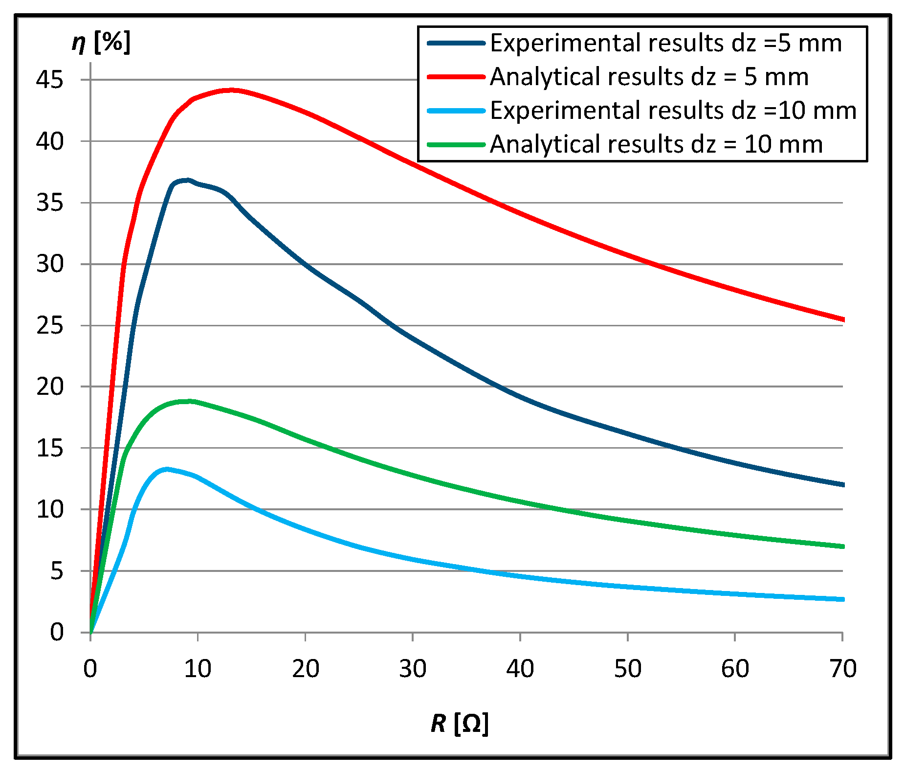
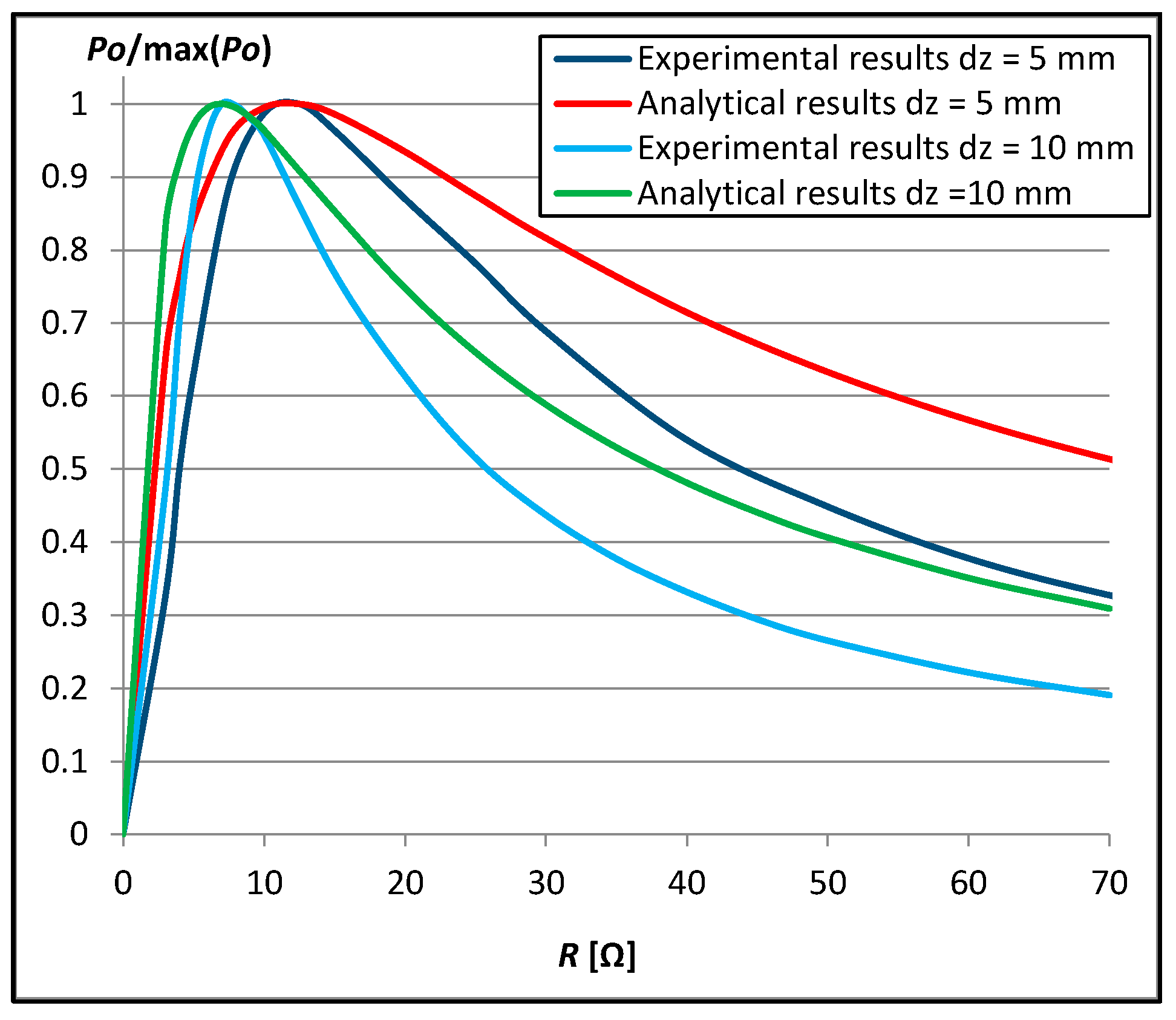
3.2. Comparison of Results at Both Distances between Planes

In this section was presented a comparison of the efficiency and receiver power results, depending on the distance dz between the transmitting and receiving planes and taking into account the load resistance, obtained experimentally and analytically (Figure 10 and Figure 11). Results from the experimental study are presented as solid blue and light blue lines at the small and large distances, respectively (marked as Experimental results in the legend). Results from the circuit model are presented as solid red and green lines at the small and large distances, respectively (marked as Analytical results in the legend).
Efficiency and receiver power diagrams are presented in Figure 10 and Figure 11.
As the distance dz between the transmitting and receiving planes increases, the efficiency of the WPT system decreases (Figure 10). The maximum efficiency of the WPT system decreased more than two times to less than 20% when the distance between the coils (dz) was doubled. The maximum efficiency obtained from calculations was 44.13% with R = 12.5 Ω and from measurements 36.83% with R = 9 Ω at the small distance dz. The maximum efficiency obtained from calculations was 18.80% with R = 9 Ω and from measurements 13.25% with R = 7 Ω at the large distance dz. The maximum receiver power was obtained with the same load resistance from measurements and calculations (12.5 Ω) at the small distance dz (Figure 11). Doubling the distance dz resulted in the maximum receiver power being obtained with R = 7 Ω for both measurements and calculations.
Results obtained for the efficiency of the WPT system are presented numerically in Table 3. Results from measurements and calculations are presented for small and large distance dz.
The difference between the experimental and computational results presented in Table 3 is larger for the system at the small distance (dz) than for the system at the large distance. The greatest difference in efficiency obtained from calculations and measurements was approximately 15% with R = 40 Ω at the small distance. The greatest difference in efficiency obtained from calculations and measurements was approximately 8% with R = 20 Ω at the large distance.

4. Conclusions

In this paper was presented the analysis of a multi-coil Wireless Power Transfer system. The WPT system consisted of identical spiral circular coils and provided power to low-power devices. These coils were arranged to form transmitting and receiving planes. Taking into account the skin effect and mutual couplings, this system was described. A detailed analysis of the system at the resonant frequency was made. The calculations were verified experimentally. The efficiency and receiver power were obtained for various loads and at two distances between the planes. The results were compared and discussed.
The maximum efficiency obtained from calculations was about 45% at the small distance between the planes and decreased more than twice to less than 20% when the distance between the coils was doubled. The maximum efficiency obtained from measurements was over 7% lower than from calculations at the distance dz = 5 mm and almost 6% lower at the distance dz = 10 mm. The load resistance changed depending on the distance between the transmitting and receiving planes, i.e., the larger the distance, the lower the load resistance at which maximum efficiency occurred. The maximum efficiency of the WPT system decreased more than two times when the distance between the coils was doubled. In all analyzed cases, the shape of the characteristics obtained from calculations and measurements was maintained. Theoretical calculations can be helpful in estimating the load resistance in order to obtain the highest possible efficiency of the WPT system or the receiver power already at the stage of preliminary calculations.

Funding

The printing of the article was financed from the ZIREG project—Integrated Program of the Bialystok University of Technology for Regional Development, contract no. POWR.03.05.00-00-ZR22/18. Project co-financed by the European Union from the European Social Fund under the Knowledge Education Development Operational Program 2014–2020.

Data Availability Statement

Data are contained within the article.

Conflicts of Interest

The author declares no conflict of interest.

References

  1. Sołjan, Z.; Hołdyński, G.; Zajkowski, M. The mathematical concept of the currents’ asymmetrical components in three-phase four-wire systems with sinusoidal and asymmetric voltage supply. Bull. Pol. Acad. Sci. Tech. Sci. 2019, 67, 271–278. [Google Scholar] [CrossRef]
  2. Sun, L.; Ma, D.; Tang, H. A review of recent trends in wireless power transfer technology and its applications in electric vehicle wireless charging. Renew. Sustain. Energy Rev. 2018, 91, 490–503. [Google Scholar] [CrossRef]
  3. Okasili, I.; Elkhateb, A.; Littler, T. A Review of Wireless Power Transfer Systems for Electric Vehicle Battery Charging with a Focus on Inductive Coupling. Electronics 2022, 11, 1355. [Google Scholar] [CrossRef]
  4. Batra, T.; Schaltz, E.; Ahn, S. Effect of ferrite addition above the base ferrite on the coupling factor of wireless power transfer for vehicle applications. J. Appl. Phys. 2015, 117, 17D517. [Google Scholar] [CrossRef]
  5. Inoue, K.; Kusaka, K.; Itoh, J.I. Reduction in radiation noise level for inductive power transfer systems using spread spectrum techniques. IEEE Trans. Power Electron. 2018, 33, 3076–3085. [Google Scholar] [CrossRef]
  6. Li, X.; Tang, C.; Dai, X.; Deng, P.; Su, Y. An inductive and capacitive combined parallel transmission of power and data forwireless power transfer systems. IEEE Trans. Power Electron. 2018, 33, 4980–4991. [Google Scholar] [CrossRef]
  7. Kang, S.H.; Choi, J.H.; Jung, C.W. Magnetic resonance wireless power transfer using three-coil system with single planar receiver for laptop applications. IEEE Trans. Consum. Electron. 2015, 61, 160–166. [Google Scholar]
  8. Barman, S.D.; Reza, A.W.; Kumar, N.N.; Karim, M.E.; Munir, A.B. Wireless powering by magnetic resonant coupling: Recent trends in wireless power transfer system and its applications. Renew. Sust. Energy Rev. 2015, 51, 1525–1552. [Google Scholar] [CrossRef]
  9. Nithiyanandam, V.; Sampath, V. Approach-Based Analysis on Wireless Power Transmission for Bio-Implantable Devices. Appl. Sci. 2023, 13, 415. [Google Scholar] [CrossRef]
  10. Fitzpatrick, D.C. Implantable Electronic Medical Devices; Academic Press: San Diego, CA, USA, 2014; pp. 7–35. [Google Scholar]
  11. Sugino, M.; Kondo, H.; Takeda, S. Linear motion type transfer robot using the wireless power transfer system. In Proceedings of the 2016 International Symposium on Antennas and Propagation (ISAP), Okinawa, Japan, 24–28 October 2016; pp. 508–509. [Google Scholar]
  12. Matetić, I.; Štajduhar, I.; Wolf, I.; Ljubic, S. Improving the Efficiency of Fan Coil Units in Hotel Buildings through Deep-Learning-Based Fault Detection. Sensors 2023, 23, 6717. [Google Scholar] [CrossRef]
  13. Stankiewicz, J.M. Comparison of the efficiency of the WPT system using circular or square planar coils. Przegląd Elektrotechniczny 2021, 97, 38–43. [Google Scholar] [CrossRef]
  14. Stankiewicz, J.M. Evaluation of the Influence of the Load Resistance on Power and Efficiency in the Square and Circular Periodic WPT Systems. Energies 2023, 16, 2950. [Google Scholar] [CrossRef]
  15. Micus, S.; Padani, L.; Haupt, M.; Gresser, G.T. Textile-Based Coils for Inductive Wireless Power Transmission. Appl. Sci. 2021, 11, 4309. [Google Scholar] [CrossRef]
  16. Sun, D.; Chen, M.; Podilchak, S.; Georgiadis, A.; Abdullahi, Q.S.; Joshi, R.; Yasin, S.; Rooney, J.; Rooney, J. Investigating flexible textile-based coils for wireless charging wearable electronics. J. Ind. Text. 2020, 50, 333–345. [Google Scholar] [CrossRef]
  17. Stankiewicz, J.M. Analysis of the Influence of the Skin Effect on the Efficiency and Power of the Receiver in the Periodic WPT System. Energies 2023, 16, 2009. [Google Scholar] [CrossRef]
  18. Lee, S.-H.; Lorenz, R.D. Development and validation of model for 95%-efficiency 220-W wireless power transfer over a 30-cm air gap. IEEE Trans. Ind. Appl. 2011, 47, 2495–2504. [Google Scholar] [CrossRef]
  19. Choroszucho, A.; Pieńkowski, C.; Jordan, A. Electromagnetic wave propagation into building constructions. Przegląd Elektrotech. 2008, 84, 44–49. [Google Scholar]
  20. Solouma, N.H.; Kassahun, H.B.; Alsharafi, A.S.; Syed, A.; Gardner, M.R.; Alsharafi, S.S. An Efficient Design of Inductive Transmitter and Receiver Coils for Wireless Power Transmission. Electronics 2023, 12, 564. [Google Scholar] [CrossRef]
  21. Sampath, J.P.K.; Alphones, A.; Shimasaki, H. Coil design guidelines for high efficiency of wireless power transfer (WPT). In Proceedings of the 2016 IEEE Region 10 Conference (TENCON), Singapore, 22–25 November 2016; pp. 726–729. [Google Scholar]
  22. Prengel, S.; Helwig, M.; Modler, N. Lightweight coil for efficient wireless power transfer: Optimization of weight and efficiency for WPT coils. In Proceedings of the 2014 IEEE Wireless Power Transfer Conference, Jeju, Republic of Korea, 8–9 May 2014; pp. 96–99. [Google Scholar]
  23. Zhang, Y.; Lu, T.; Zhao, Z. Reducing the impact of source internal resistance by source coil in resonant wireless power transfer. In Proceedings of the 2014 IEEE Energy Conversion Congress and Exposition (ECCE), Pittsburgh, PA, USA, 14–18 September 2014; pp. 845–850. [Google Scholar]
  24. Stankiewicz, J.M. Estimation of the Influence of the Coil Resistance on the Power and Efficiency of the WPT System. Energies 2023, 16, 6210. [Google Scholar] [CrossRef]
  25. Choroszucho, A. Analysis of the influence of electrical parameters of concrete and reinforcement inside concrete walls on the values of the electric field intensity. Przegląd Elektrotechniczny 2022, 98, 111–117. [Google Scholar] [CrossRef]
  26. Stankiewicz, J.M.; Choroszucho, A. Comparison of the Efficiency and Load Power in Periodic Wireless Power Transfer Systems with Circular and Square Planar Coils. Energies 2021, 14, 4975. [Google Scholar] [CrossRef]
  27. Li, J.; Huang, X.; Tan, L.; Wang, R. Resistance optimization of a coil with substrate and design of a high-power-density coupler for wireless power transfer. ISA Trans. 2022, 137, 692–705. [Google Scholar] [CrossRef] [PubMed]
  28. Stankiewicz, J.M. The analysis of the influence of the plane coils geometry configuration on the efficiency of WPT system. Przegląd Elektrotechniczny 2020, 96, 174–178. [Google Scholar] [CrossRef]
  29. Yuan, Z.; Yang, Q.; Zhang, X.; Ma, X.; Wang, R.; Xue, M.; Zhang, P. A Misalignment Tolerate Integrated S-S-S-Compensated WPT System with Constant Current Output. Energies 2023, 16, 2798. [Google Scholar] [CrossRef]
  30. Wu, J.; Wang, Z.; Dai, X. Constant Output-Voltage Design for Bi-Directional Wireless Power Transfer System with Multiple Stages. Energies 2020, 13, 3739. [Google Scholar] [CrossRef]
  31. Rong, C.; Yan, L.; Li, L.; Li, Y.; Liu, M. A Review of Metamaterials in Wireless Power Transfer. Materials 2023, 16, 6008. [Google Scholar] [CrossRef]
  32. Steckiewicz, A. Efficient Transfer of the Medium Frequency Magnetic Field Using Anisotropic Metamaterials. Energies 2023, 16, 334. [Google Scholar] [CrossRef]
  33. Liu, S.; Su, J.; Lai, J. Accurate Expressions of Mutual Inductance and Their Calculation of Archimedean Spiral Coils. Energies 2019, 12, 2017. [Google Scholar] [CrossRef]
  34. Torki, J.; Joubert, C.; Sari, A. Electrolytic capacitor: Properties and operation. J. Energy Storage 2023, 58, 106330. [Google Scholar] [CrossRef]
  35. Knight, D.W. Practical Continuous Functions for the Internal Impedance of Solid Cylindrical Conductors; G3YNH: Southport, UK, 2016. [Google Scholar] [CrossRef]
Figure 1. The transmitting and receiving planes forming the analyzed WPT system.
Energies 16 07651 g001
Figure 2. The transmitting and receiving planes: the electric circuits.
Energies 16 07651 g002
Figure 3. Experimental stand containing transmitting and receiving planes.
Energies 16 07651 g003
Figure 4. Results of the efficiency for different load resistances (dz = r/2 = 5 mm).
Energies 16 07651 g004
Figure 5. Results of the active power of the receiver for different load resistances (dz = r/2 = 5 mm).
Energies 16 07651 g005
Figure 6. Results of the active power of the transmitter for different load resistances (dz = r/2 = 5 mm).
Energies 16 07651 g006
Figure 7. Results of the efficiency for different load resistances (dz = r = 10 mm).
Energies 16 07651 g007
Figure 8. Results of the active power of the receiver for different load resistances (dz = r = 10 mm).
Energies 16 07651 g008
Figure 9. Results of the active power of the transmitter for different load resistances (dz = r = 10 mm).
Energies 16 07651 g009
Figure 10. Results of the efficiency for different load resistances.
Energies 16 07651 g010
Figure 11. Results of the active power of the receiver for different load resistances.
Energies 16 07651 g011
Table 1. Parameters of the WPT system model.
r (mm)ntdz (mm)
1030510
Table 2. Parameters used in the analysis.
ParameterSymbolValue
wire diameterwc200 µm
wire insulation thicknesswi5 µm
wire conductivityσw5.6 107 S/m
resistance increase coefficientkR1.25
dissipation factorDF0.05
separation between coilsds0.025 m
design frequencyfc500 kHz
Table 3. Comparison of results at both distances between planes.
Load Resistanceη (%)
CalculationsMeasurements
dz = 5 mmdz = 10 mmdz = 5 mmdz = 10 mm
328.8913.7318.406.70
433.4715.7924.739.71
536.7817.1428.7411.72
740.9118.5035.2613.25
7.541.5818.6836.1813.19
842.1818.7436.6813.14
943.0218.8036.8312.92
1043.5718.7336.5312.60
12.544.1318.1435.8011.39
1543.9017.4233.6610.20
2042.3615.7229.968.37
2540.2914.1427.016.94
3038.1312.7723.935.92
4034.1210.6319.184.54
5030.729.0716.163.69
6027.887.8913.783.10
7025.506.9812.022.67
Disclaimer/Publisher’s Note: The statements, opinions and data contained in all publications are solely those of the individual author(s) and contributor(s) and not of MDPI and/or the editor(s). MDPI and/or the editor(s) disclaim responsibility for any injury to people or property resulting from any ideas, methods, instructions or products referred to in the content.

