Article

Optimized Distributed Cooperative Control for Islanded Microgrid Based on Dragonfly Algorithm

by
Falah Noori Saeed Al-dulaimi
1,2,* and
Sefer Kurnaz
1
1
School of Engineering and Natural Sciences, Altinbas University, Istanbul 34218, Turkey
2
Electrical Engineering Technical College, Middle Technical University, Baghdad 10001, Iraq
*
Author to whom correspondence should be addressed.
Energies 2023, 16(22), 7675; https://doi.org/10.3390/en16227675
Submission received: 29 October 2023 / Revised: 15 November 2023 / Accepted: 17 November 2023 / Published: 20 November 2023
(This article belongs to the Section A2: Solar Energy and Photovoltaic Systems)

Abstract

:
This study introduces novel stochastic distributed cooperative control (SDCC) in the context of island microgrids (MGs). A proportional resonant (PR) controller and virtual impedance droop control in stationary reference frames are employed in cooperation with distributed averaging secondary control optimized by the dragonfly algorithm (DA). The suggested approach demonstrates the capability to achieve mean-square synchronization for the voltage and frequency restoration of distributed generators (DGs) to ensure efficient active power sharing. Therefore, a sparse communication network has been used to avoid data congestion and reduce the need for extensive communication and information exchange. The proposed system offers an instinctive compromise between voltage regulation and reactive power sharing. A conventional centralized secondary control with PR droop control is simulated for performance evaluation and comparison purposes. In this study, empirical evidence is demonstrated to support the MG’s ability to confront communication failure and its ability to work reliably during plug-and-play operations.

1. Introduction

In consideration of the persistent upward trajectory in economic growth, environmental concerns, heightened power service reliability, improved power quality, and the pursuit of independence from conventional energy sources, the incorporation of renewable energy sources (RESs) has become imperative within the contemporary power industry [1]. Consequently, there is a continual increase in the adoption of DG-utilizing RESs. The optimal efficiency of DGs is attainable through their strategic installation proximal to the load end. Examples of DGs encompass mini- and micro-scale hydroelectric plants, wind turbines, fuel cells, solar energy systems, and biomass facilities. The contemporary power industry is gravitating towards dispersed generation to achieve a reliable power supply with enhanced dependability. The integration of DGs necessitates a comprehensive impact analysis as an integral aspect of power network planning [2]. A prevailing preference exists for the integration of DGs on the distribution side, aimed at achieving improved stability and voltage profiles, minimizing both active and reactive power losses, and ensuring cost-effectiveness.
The MG could be described as a configuration consisting of power DGs, storage system technologies, and loads [3]. MGs can be categorized into three distinct classifications based on their bus types, specifically alternating current (AC), direct current (DC), and hybrid DC/AC. In island MGs, where voltage and frequency changes may result in no backup from the main grid, an effective control structure is needed to optimize system performance. The authors of this study have presented hierarchical control systems for MGs to address their needs [4]. The hierarchical control technique comprises three distinct levels: primary, secondary, and tertiary. The primary level, also referred to as local control (LC), is primarily concerned with frequency and voltage regulation, as well as the distribution of power [5]. The droop control technique poses certain difficulties, such as variances in voltage and frequency from their designated values [6]. The primary control level is tasked with executing control actions, and is reliant on the upper control level, particularly the secondary control, for its set points (refer to Figure 1).
There are several secondary control (SC) approaches designed to mitigate this type of problem. A centralized controller, the MG central controller (MGCC), is proposed in reference [3]. However, the centralized SC strategy has downsides as the system expands, such as high processing costs, higher communication needs, and reduced resilience due to reliance on global information from DGs. In order to overcome these obstacles, the secondary layer has been outfitted with decentralized and distributed control mechanisms. Each DG in a distributed system will poll its neighbors for data [7]. Each DG collects data on voltage and current magnitudes from its neighboring units [8]. Centralized techniques have also been implemented in MG situations, where the concept of “secondary” has been expanded to encompass supplementary control objectives, such as the distribution of reactive power. Ref. [9] proposes voltage stabilization and harmonic regulation [10,11]. The highest level of tertiary control entails the optimization of global economic dispatch across the network, which is dependent on the current energy markets and pricing. Nevertheless, in the context of extensive MGs, the utilization of these decentralized controllers may result in substantial expenses related to communication. In order to tackle this matter, sophisticated distributed controllers, which integrate event-triggered communication techniques, have been implemented as a viable resolution [12]. Reference [13] presents a novel approach to distributed voltage regulation that does not require constant communications. The aforementioned elements have the potential to exert adverse effects on system performance and, in extreme cases, may result in system breakdowns [14]. Communication lines and local controls (LCs) are two MG components that this article emphasizes are susceptible to cyberattacks [15]. Malicious hackers pose a threat to MGs from both internal and external sources [16]. Many studies have been conducted on this topic, considering factors such as communication security, robustness, and economic considerations [17,18]. The techniques obviate the necessity of information sharing among DGs, with each DG’s controller being exclusively developed using its own localized information. In the recent literature, references [19,20] have shown the emergence of sophisticated decentralized control methods accompanied by thorough analysis. Addressing these issues has been a primary focus within the realm of study up to this point. Distributed control strategies have been found to be helpful in improving the speed at which DGs restore frequency. One of the control systems employed is the proportional–integral (PI) controller. Consequently, a transformation from the frame to the alpha beta frame, known as Clarke transform, becomes necessary. One significant limitation of this approach is the substantial processing burden incurred while managing numerous frequencies and both negative and positive sequences in the context of extensive mathematical transformations. Due to the aforementioned factors, a viable substitute for this approach has been suggested in the form of a PR controller [21].
A PI regulator secondary controller for active restoration was created in [22,23]. Switching failure and power-sharing degradation are hazards of PI-based SC. In [24], a fuzzy SC controller dampened voltage and frequency aberrations with greater band width. The performance was influenced by the utilization of fixed fuzzy rules in the design of the controller. A finite-time SC method was described in [25] for precisely reactive power-share and to regulate an islanded MG’s frequency and voltage. Intelligent techniques fix such flaws to improve MG performance in diverse operating settings. Intelligent methodologies are employed to effectively manage the intricacies associated with model complexity, uncertainty, and nonlinearity within power electronic applications due to their model-free structure. The model-free brain–emotional learning-based intelligent controller has a simple control structure [26], making it suitable for real-time applications. The dragonfly algorithm (DA), initially proposed by Mirjalili in 2014, represents a recently developed heuristic algorithm inspired by the unique swarming behavior of dragonflies. DA has demonstrated superior performance compared to several existing swarm-based algorithms documented in the literature [27].
Inspired by previous discussions, this article describes a new stochastic distributed cooperative control (SDCC) technique-based model-free adaptive controller for correct voltage and frequency compensator signals in VSC-based island AC MGs. Therefore, neither system parameters nor structures are needed beforehand. Unlike conventional controllers, the SDCC is independent of operational conditions and performs well in instabilities and load disturbances. A mathematical model evaluates the controller’s convergence conditions. The control technique is compared to centralized secondary controllers. The proposed control strategy uses proportional resonant (PR) and virtual impedance droop control in stationary reference frames and intelligently distributed SC optimized by the dragonfly algorithm (DA) to correct for steady-state voltage and frequency changes and maintain the allocation of active and reactive power during both steady-state and transitional operating conditions. The proposed method combines ideas from graph theory and randomness theory to measure stability and convergence.
The study highlights how crucial establishing slight communication is to achieve the desired frequency and voltage restoration and mitigating data congestion. Three different DGs are arranged in a non-parallel arrangement in the actual MG setup, which also incorporates high R/X connections and distributed load. By testing the controller’s performance in scenarios involving plug-and-play operation and communication link failures, we prove the effectiveness of our designs and go beyond theoretical conclusions. The main contributions to our article are presented below:
  • A novel SDCC for optimal voltage and frequency restoration and active and reactive power sharing is proposed in this study. This approach to therapy is based on PR and virtual impedance droop control in stationary reference frames and intelligent distributed SC optimized by the dragonfly algorithm.
  • The paper examines the impact of computational budget limits and the deployment of optimization strategies on resource consumption, ultimately leading to optimal efficiency.
  • The article aims to enhance system performance and reduce resource demands by developing precise models that are compatible with constrained processors and using optimization strategies.
  • Evaluating the effectiveness of the technique through a comparative analysis of the system’s resilience in the event of communication loss and its reliability during plug-and-play operation.

2. Preliminaries and MG Control Review

This section commences with the introduction of the MG model, which integrates primary control. Furthermore, we will examine the power flow analysis and issue formulation for an island MG. Following this, we proceed to define the issue that requires attention and present an extensive clarification of the corresponding control objectives.

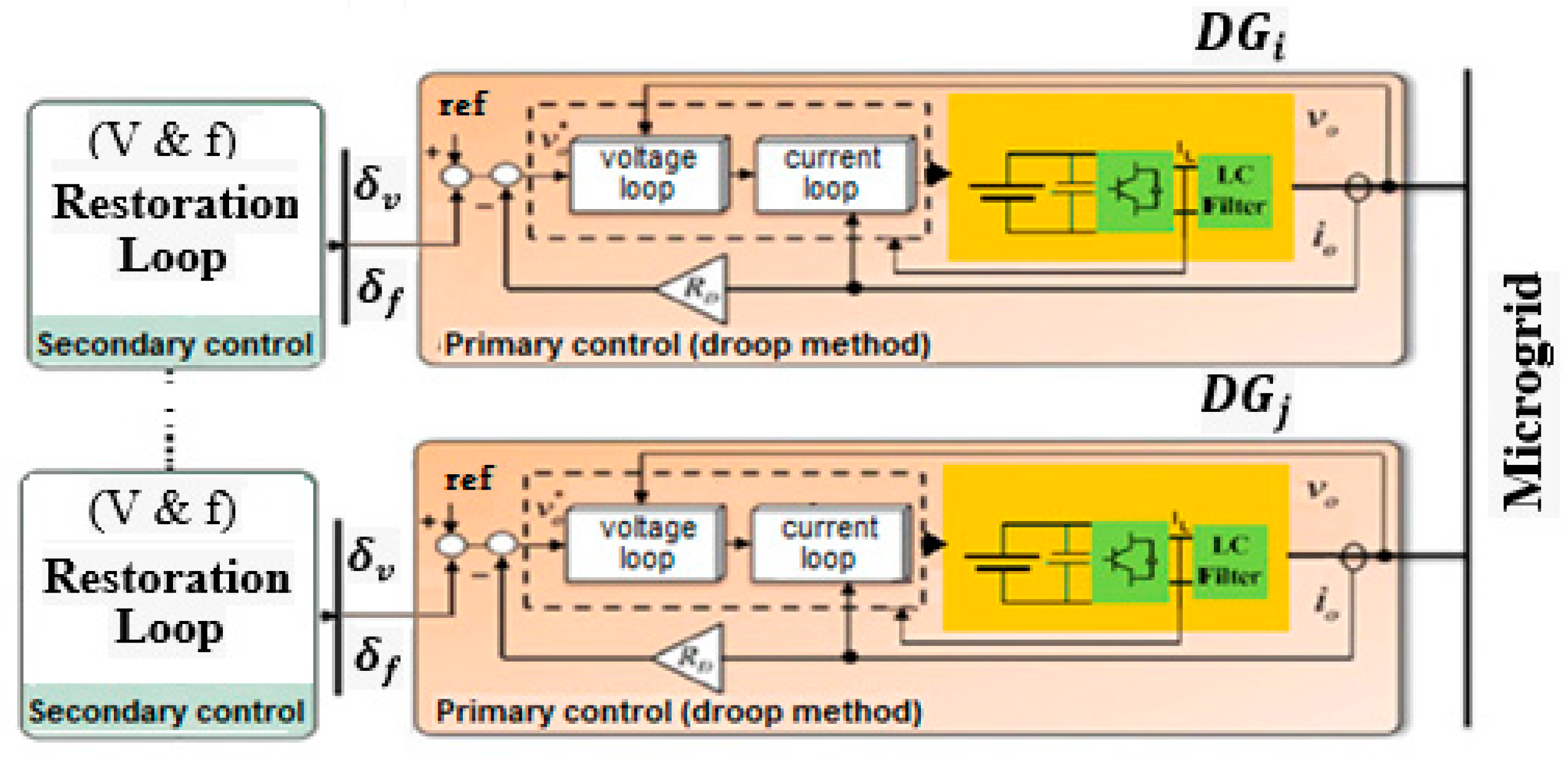
2.1. Primary Level Review

In this analysis, we will examine an AC MG system that is comprised of N DGs operating on alternating current (AC) and utilizing inverters. Every DG is equipped with its own primary controller that operates in a decentralized manner. The basic controller is composed of three distinct components, namely a droop control loop and a voltage/current control loop. Figure 1 illustrates the schematic diagram depicting an inverter-based DG. The droop control loop exerts a substantial influence on the overall performance of the primary control system, although the stability of the voltage and current loops remains intact. The primary control level, also referred to as droop control, is of paramount importance in maintaining voltage and frequency stability inside the MG. Additionally, it establishes the reference values for the control loops of voltage and current. The correlation between active power and frequency in DGs can be mathematically represented as follows [28]:
ω i = ω s e t m P i P i
In this context, the symbol ( ω s e t ) represents the nominal frequency. The symbol m P i represents the droop coefficients, while P i represents the active power measurement. To reinstate islanded MG frequency to its designated value, the variable δ u ω i is integrated into the droop equation in the following manner:
ω i = ω s e t m P i P i + δ u ω i
In this context, the symbol δ u ω i depicts the compensator signal utilized in secondary frequency management. DG set points are adjusted by the main control layer, specifically the droop control reference ω s e t in Equation (1). The control layer is responsible for determining the value of ω s e t , which facilitates the synchronization of the angular frequencies of DGs with the nominal angular frequency. Additionally, it allocates the active power of the DGs according to predetermined criteria.
P 1 P m a x , 1 = = P N P m a x , N
In this context, P m a x , 1 denotes the rating value of active power for the D G i . The selection of droop coefficients, denoted as m P , i , is based on the ratings of DGs active power. Therefore, it is imperative to create a correlation between the active power and droop coefficient:
m P 1 P 1 = = m P N P N
In order to clarify the problem of secondary frequency management, Equation (2) has been derived as:
P N ω i ˙ = ω s e t ˙ m P i P i ˙ + δ ˙ u ω i = u ω i
The symbol u ω i denotes an auxiliary control input. Consequently, the next statement is derived:
ω i = u ω i d t
Based on Equation (5), it can be observed that the frequency restoration process in a MG comprised of DGs may be mathematically represented as a monitoring synchronization challenge:
ω i ˙ = u ω i ,   i = 1 ,   .   ,   N
The SC level serves as a crucial factor in facilitating the reliable, secure, and cost-effective operation of the MG. During the MG’s steady-state operation, the SC mechanism oversees bringing the frequency back to its set value and making up for any changes in the primary level. AC MGs have pinned DGs and followed DGs. The main goal of SC in AC MGs is to achieve frequency recovery and power sharing.
lim t ω i ω s e t = 0   ,     i , lim t m P i P i m P j   P j = 0   ,   i ,   j

2.2. Cooperative Control Objective

Taking into account the non-linear large-scale DG model and ignoring the changes in direct current (DC) bus voltage and switching harmonics, we assume that there are inductive distribution lines and that the DGs can talk to each other without interruption. In the given circumstances, it is possible to identify the ( P / a c t i v e   and   Q / r e a c t i v e ) power provided by the DG situated in i t h position within the distribution network [29].
P i = j = 1 n E i E j sin ( θ i θ j ) Z i j
Q i = E i 2 Z i j = 1 n E i E j sin ( θ i θ j ) Z i j
The calculation of the ( P i ) and ( Q i ) produced by the i t h DG can be established by considering the output voltage at bus i ( E i θ i ) of the DG and the voltage at bus j ( E j θ j ). The effective collective impedance ( Z i j ) encompasses both the output filter of the DG and the connector that connects bus i to bus j . On the other hand, ( Z i ) refers to the 1 j = 1 n X i j 1 at bus i . Additionally, the symbol ω r e f denotes the frequency reference value, whereas ( v r e f 1 , v r e f 2 ) represents the upper and lower voltage amplitude limitations. The primary aim of this summary is to ensure that the voltage amplitude of every node remains within a predetermined range, denoted as V i ∈ [ v r e f 1 , v r e f 2 ]. Through Equations (9) and (10), which implement the ( P   and   Q ) droop strategies as in Equation (1), cooperative control is enabled:
ω i = ω s e t m P i P i ,
v o i = V s e t n Q i Q i ,
By employing a suitable reference coordinate transformation, the resultant voltage ( v o i ) adjustment can be likened to the voltage magnitude ( E i ) adjustment. The variable V s e t denotes the desired value for the droop mechanism in the SC. The coefficient n Q i is determined by considering the power rating of the associated DG system. The generation of the frequency error term u ω i (depending on cooperative control action) can be achieved by means of collaborative efforts among DGs [30]:
u ω i = j = 1 N a i j ω i ω j a i 0 ( ω i ω r e f ) ,
Likewise, the voltage error term ( u v i ) is formulated as follows:
u v i = j = 1 N a i j V i V j a i 0 ( V i V r e f ) ,
The variable a i 0 represents the pinning gain of D G i . In order to achieve proper coordination between the voltages, DGs terminal frequencies and their respective reference values, the SC mechanism generates local values for ω i and V i . The aforementioned objective is accomplished by engaging in data exchange with adjacent DGs inside the directed communication graph. These values are subsequently modified by taking into consideration the voltage error term u v i and the frequency error term u ω i [31].

2.3. Secondary Level Review

The utilization of “secondary” integral controllers aims to effectively mitigate the system parameter variations (voltage and frequency) that are generated by the droop controllers (11) and (12) in a steady-state approach.

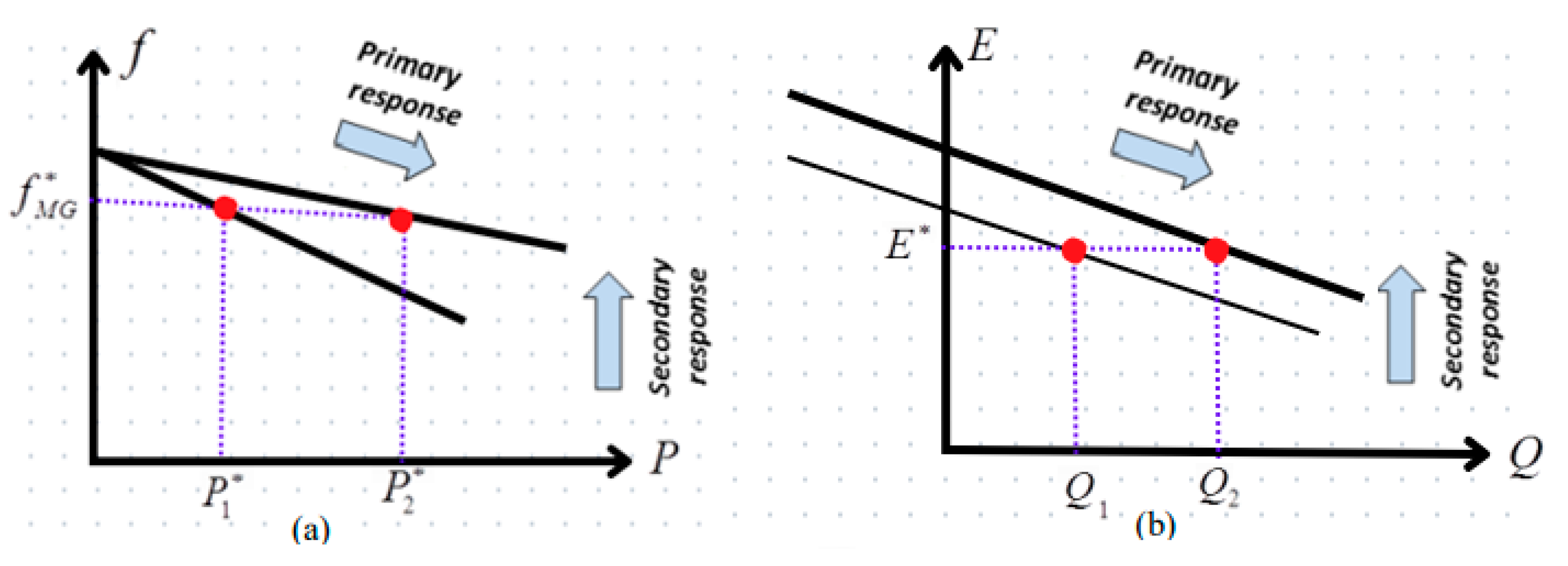
2.3.1. Frequency Control

A variety of techniques have been suggested for the restoration of network frequency, encompassing both centralized and decentralized approaches [32]. Each strategy possesses its own merits and demerits. A centralized approach is employed to replicate the functionality of Automatic Generation Control, as is observed in large-scale electrical grids [33]. In contrast, a decentralized approach entails the implementation of slower integral control at each individual inverter [29]. The underlying assumption of this approach is that the local frequency being monitored, which enforces synchronization, operates at a quicker rate compared to the secondary integral controller, which operates at a slower rate. But, with a few exceptions, this decentralized approach weakens the power-sharing features created by the primary control [22], and it has been shown that it is not good enough at adjusting the grid frequency when the load changes quickly. In the DSC field, each DG unit conducts measurements of its respective frequency and disseminates these data to all other DG units. Subsequently, every DG unit proceeds to compute the mean value of the frequencies it receives from other DG units, employing this mean value to internally restore its own frequency [34]. Figure 2a depicts the SC technique employed to correct frequency discrepancies resulting from the primary controller.

2.3.2. Voltage Control

In high-voltage systems, the distribution of reactive power demand between units is typically not a major concern, as capacitive compensation is employed for both loads and transmission lines. Consequently, the generators’ voltages are regulated to predetermined values by the implementation of the excitation system [35]. As a result, voltage regulation has emerged as the prevailing method of implementing voltage SC in MGs [36].
The line impedance effect makes it hard for the voltage droop controller (Equation (12)) to divide reactive power demand among parallel–identical inverters in an efficient way. In a previous study [17], a different primary droop controller was suggested to deal with this problem. The goal was to achieve reactive power distribution across parallel inverters with the same rated voltages. Furthermore, the distributed voltage controller, as described in [37], requires the establishment of direct communication among all DGs. But, because the controller’s job is to keep the voltages of DG systems at their nominal values, it cannot distribute reactive power well between different units that are connected by lines with different impedances. Figure 2b illustrates the SC implementation that was employed to mitigate the voltage variation resulting from the operation of the droop controller.

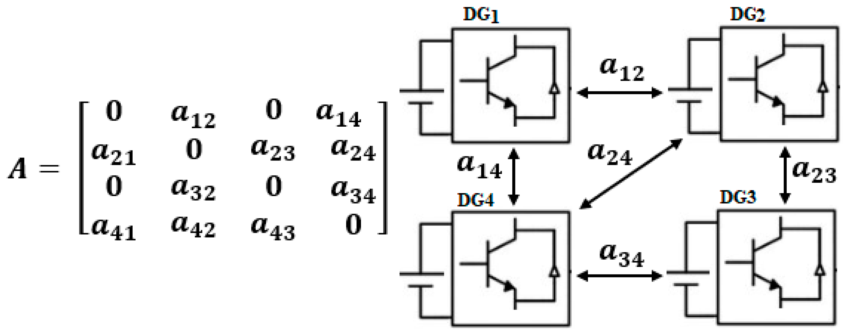
2.4. Graph Theory Concept

The communication layer between distributed generators (DGs) is denoted by a weighted G( ν , ε , A ), where ν = {1, …, n} represents the labels assigned to the DGs, ε is the set of communication links between the DGs, and A is the weighted adjacency matrix of the graph. The elements of the adjacency matrix, a i j = a j i ≥ 0, are non-negative. The existence of an element i , j ε signifies that node i transmits information directly to node j , where a i j > 0 . The adjacency matrix is a mathematical representation used to describe the connections or relationships between vertices in a graph. The sparsity pattern serves as a representation of the communication layer’s architecture. Figure 3 is shown herein as a visual representation of the communication topology and adjacency matrix pertaining to four DGs, with the sole intention of providing a demonstrative context [38].

3. Voltage Control Restrictions

The achievement of accurate allocations of reactive power among DG units presents challenges due to multiple factors. Firstly, in contrast to frequency, voltage does not possess a universal characteristic, hence making its regulation more difficult [34]. In the simple MG system shown in Figure 4a, the variations in voltage and impedance across DG units, as illustrated in Figure 4b, pose a significant challenge in achieving precise reactive power sharing through Q-E droop management.
This section will discuss two situations [29]. Firstly, let us consider the scenario in which two parallel inverters, which are identical and parallel to each other, are depicted in Figure 4a. These inverters are functioning by means of reactive lines, with the condition that X 1 is greater than X 2 .

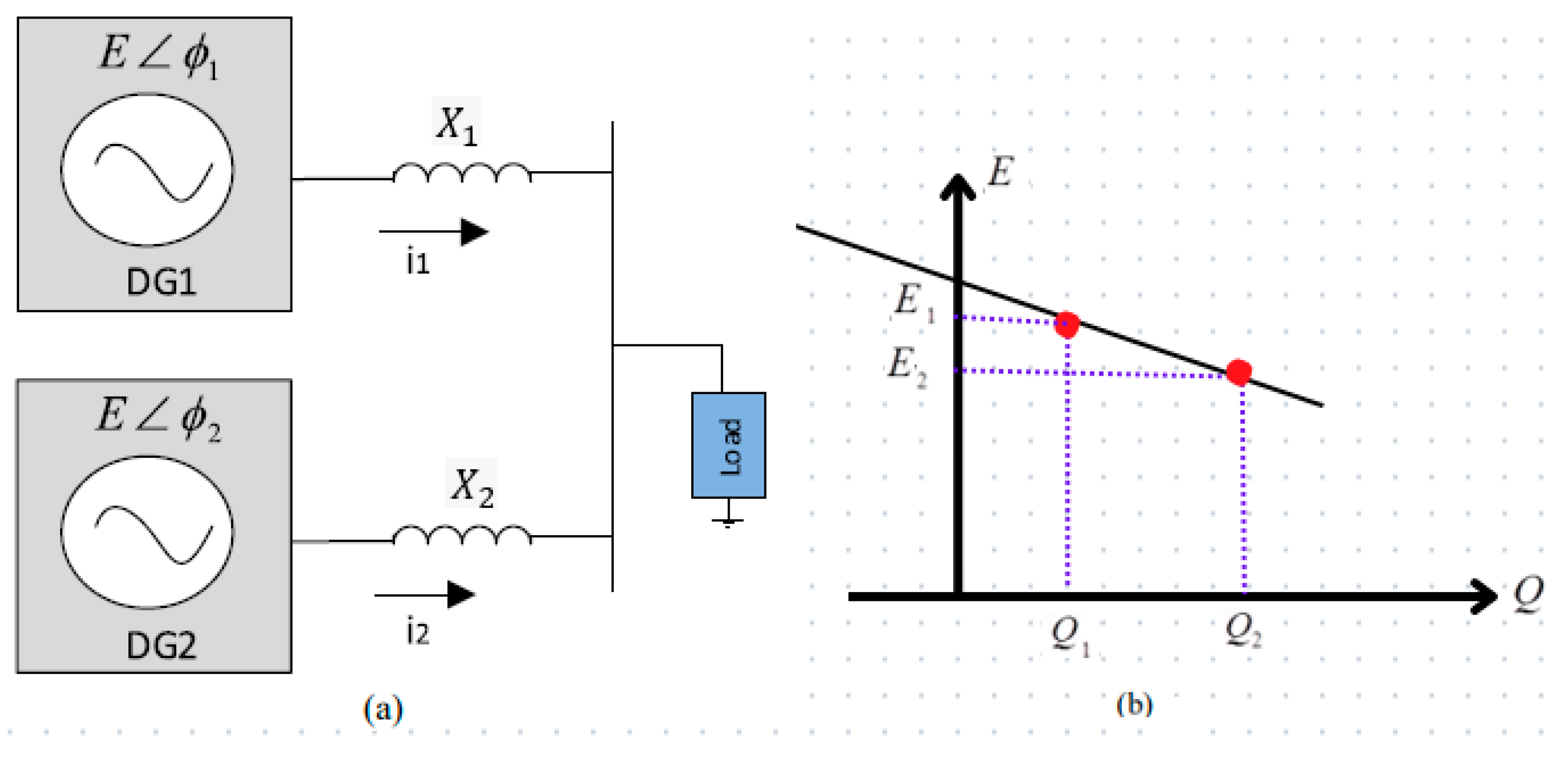
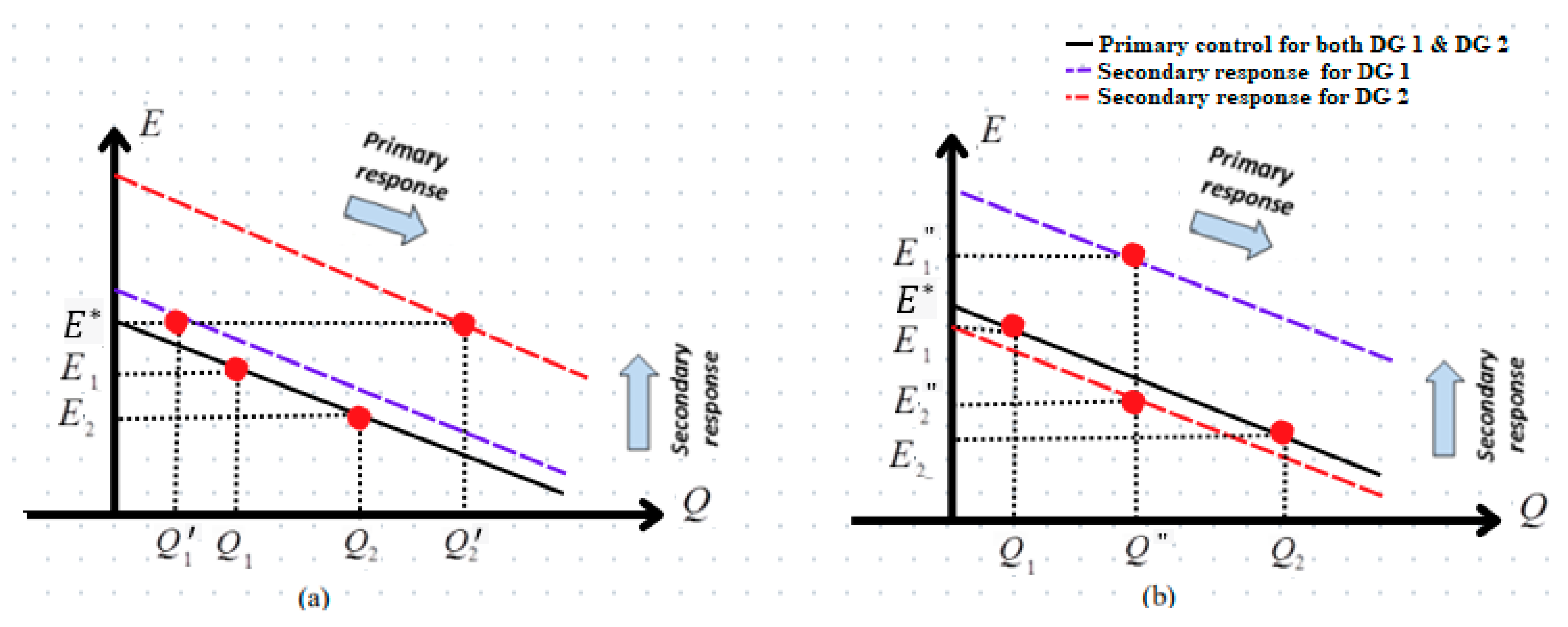
3.1. Standard Secondary Control and E-Q Droop without Power Sharing

In a scenario where there is a lack of secondary control, inverters function at voltages E 1 and E 2 , while simultaneously injecting reactive powers Q 1 and Q 2 . Given that Q 1 is not equal to Q 2 , it may be concluded that there is an absence of reactive power sharing, which is sometimes referred to as the effect of the line impedance. The use of voltage-regulating SC guarantees the restoration of both DG voltage magnitudes. Nevertheless, it is important to acknowledge that the power injections of the inverter undergo a change from Q 1 to a value less than Q 1 , and from Q 2 to a value greater than Q 2 . As a result, the utilization of conventional SC further amplifies the existing deficiency in the distribution of reactive power among the DGs, as seen in Figure 5a.

3.2. Secondary Control and E-Q Droop with Power Sharing

By injecting reactive power Q into both inverters, the reactive power is now distributed proportionally among the two inverters. Nevertheless, the voltage values E 1 and E 2 exhibit a greater dissimilarity in comparison to the scenario where just primary control was implemented, as depicted in Figure 5b. However, it should be noted that the sharing objective of reactive power does not necessarily provide a distinct solution for the DG bus voltages. Furthermore, the appropriate reactive power sharing relies on the correct implementation of uniform reactance and DG voltage restrictions. The necessity of an ideal secondary voltage controller becomes evident, as it should provide a modifiable equilibrium between reactive power and voltage regulation. The relationships between (E and Q) are presented in Table 1 for the various control actions outlined earlier.

4. Methodology: Stochastic Distributed Cooperative Control (SDCC)

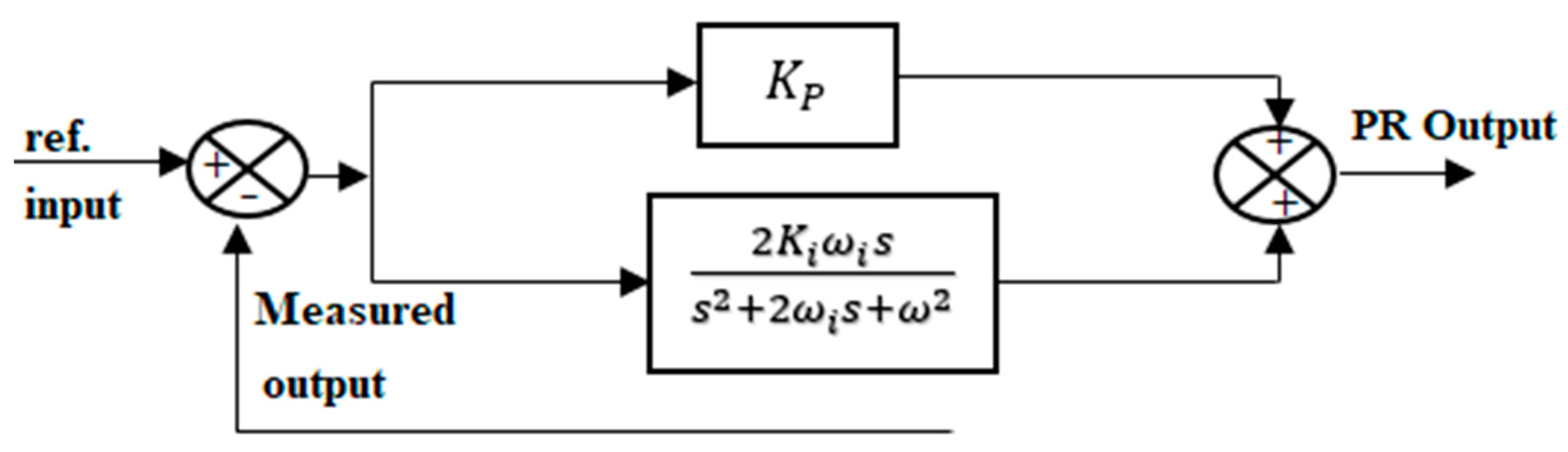
4.1. Proportional Resonant (PR) Droop Control in Stationary Reference

In recent years, there has been a noticeable rise in the use of PR controllers. The droop controller that is presented is founded on the α β reference frame. The control loops encompass proportional plus resonant (PR) terms that are adjusted to the fundamental frequency. This is mostly because PR controllers can effectively reduce the steady-state error that comes with sinusoidal signals. Furthermore, the controllers have garnered attention as suitable options for MGs due to their simple implementation, ability to compensate for low-order harmonics, and capacity to do so without impacting system dynamics or overall bandwidth. The utilization of a PR controller for the purpose of voltage harmonic removal in DG interface inverters is employed. Figure 6 depicts the execution of the PR control scheme. The math modeling of an ideal PR controller may be characterized as [39]:
G P R = K P + 2 K i s s 2 + ω 2
The variables K P and K i represent the proportional and resonant gain constants, respectively. Equation (15), which suggests the occurrence of exponential amplification at the resonant frequency, is the main cause for concern. Therefore, to achieve the bandwidth in the vicinity of the central frequency, it is necessary to incorporate a low-pass filter into the ideal mathematical model. Therefore, the mathematical model can be described in Equation (16).
G P R ( s ) = K P + 2 K i ω i s s 2 + 2 ω i s + ω 2
The variable ω i represents the bandwidth surrounding the fundamental frequency ω . The intended frequency in this case is 50 Hz. Therefore, the PR controller was specifically built to operate at a resonant frequency of 314.2 rad/s (equivalent to 50 Hz) and has a bandwidth denoted as ω i rad/s. Given the variation in the frequency 1 Hz, the frequency bandwidth was chosen to be 2π radians per second.
The utilization of a PR controller, specifically designed within the α β reference frames for the purpose of voltage regulation in a DG-interfacing inverter. The control methodology encompasses current and voltage control loops. The transfer functions of our current and voltage controller in α β reference frame can be expressed in the following manner:
G V S α = I r e f α = ( V r e f α V α ) K P V + 2   K r V   ω i S s 2 + 2 ω i s + ω 2 + I α
G V S β = I r e f β = ( V r e f β V β ) K P V + 2   K r V   ω i S s 2 + 2 ω i s + ω 2 + I β
G I S α = u α = ( I r e f α I α ) K P I + 2   K r I   ω i   S s 2 + 2 ω i s + ω 2 + v α × 1   V d c
G I S β = u β = ( I r e f β I β ) K P I + 2   K r I   ω i   S s 2 + 2 ω i s + ω 2 + v β × 1   V d c
The variables K P I / K P V are used to represent the proportional coefficients of current/voltage controllers. Similarly, the variables K r I / K r V are used to designate the resonant coefficients at the fundamental frequency, specifically ω * = 50 Hz. The variables in αβ-frames are derived through the utilization of the widely recognized Clarke transformation. Additionally, the conversion of currents and voltages occurs from the a b c reference frames to the αβ reference frames.

4.2. Virtual Impedance Loop and Droop Control in Stationary Reference

The voltage control reference generation v r e f is conducted with the aim of synchronizing VSI units. This will be achieved in conjunction with the implementation of the mentioned control loops. The droop control mechanism is tasked with modifying voltage phase and value in accordance with the ( P   and   Q ), hence facilitating control over the flow of ( P   and   Q ). The functions of the droop control may be described as follows [39]:
p h V r e f = * = ω * t G P ( s ) ( P P * )
E = E * G Q ( s ) ( Q Q * )
where ω * t = ω * d t = * is the phase reference. The active and reactive power references, denoted as P * and Q * , are typically initialized to zero. The compensator transfer functions, G P ( s ) and G Q ( s ) , are chosen according to the following selection criteria:
G P s = K P P S + K i P S
G Q s = K P Q
The static droop coefficients are denoted as K i P and K P Q , while K P P can be regarded as a system virtual inertia, commonly referred to as the transient droop term. The selection of the coefficients of the static droop K i P and K P Q can be made by considering the relationships K i P = d f / d P and K P Q = d V / d Q . The power block calculation is utilized to determine the values of ( P   and   Q ) in the αβ-frames [39].
p = 3 2 ( V c α I O α + V c β I O β )
q = 3 2 ( V c β I O α V c α I O β )
Let p/q represent the instantaneous active/reactive power, respectively. Additionally, let I O α ,   β   and V c ( α ,   β ) denote the output current and capacitor voltage, respectively. Low-pass filters are utilized to acquire P and Q by mitigating the presence of p and q waves. In addition, the voltage reference is enhanced by incorporating a virtual impedance loop. The output impedance plays a crucial role in determining the power angle and amplitude relationships (P/Q) using the droop method control law. The sinusoidal generator determines the AC signal V α β by employing the droop Equations (11) and (12) to ascertain the amplitude V and frequency, while utilizing the phase-locked loop (PLL) to calculate the phase increment d∅. In the context of a fixed reference frame, the mathematical representation of the sinusoidal generator output can be expressed as follows:
V r e f α = V cos ( ω t m P P + d )
V r e f β = V sin ( ω t m P P + d )
The gain of the MP controller is employed in practical applications to enhance the system transient response in response to rapid variations in active power. The output voltage frequency can be described mathematically as (according to the Equations (11) and (27)):
ω = ω * m P m P d P d t
The droop correction can be represented mathematically as a proportional–derivative (PD) controller, as expressed in Equation (29). In this equation, the derivative term serves as the feed-forward signal, which is utilized in Equations (27) and (28). Figure 7 presents a block diagram that depicts the virtual impedance implementation. The main impedance of a generator is mostly inductive due to the presence of the LCL filter. However, the virtual impedance can be freely chosen without any limitations. The mathematical representation of the virtual impedance expression loop in αβ-frames can be described as follows:
V α = R v · I O α ω L V · I O β
V β = R v · I O β + ω L V · I O α
Let L V and R v represent the virtual inductance and resistance values, respectively. Similarly, let I O α ,   β and V α ,   β denote the output current and voltage in the αβ-frames.

4.3. Intelligent Distributed Secondary Control Design

4.3.1. Dragonfly Algorithm

The optimization of voltage and frequency system control is of great importance in contemporary power grids, as it provides significant benefits by improving both transient and grid stability responses [40]. Dragonflies, consisting of approximately 3000 distinct species worldwide, undergo a life cycle encompassing two main stages, nymph and adult, with the nymph stage being predominant. Researchers in the field of dragonfly algorithms (DA) have drawn inspiration from the warming behaviors of dragonflies, as documented in reference [41]. Dragonflies exhibit distinct behaviors during their swarming phases. In the static swarm phase, they form small clusters and engage in exploratory activities near their habitat to hunt for prey. This phase is characterized by sudden changes in flight paths and localized movements. Conversely, in the dynamic swarm phase, a larger number of dragonflies cooperate to facilitate long-distance migration in a specific direction, with survival as their primary goal. They adapt their course to find food sources and respond to external threats. These observed behaviors give rise to five categories of positional updates for swarm individuals: alignment, control cohesion, attraction to food sources, distraction in response to external threats, and separation. Equation (32) is used to represent the spatial separation of an individual dragonfly within the swarm. This mathematical representation serves as a critical tool for modeling and understanding the complex collective behaviors of dragonfly swarms.
S i = j = 1 N X X j
In the context of this study, the variable denoted as X ″ corresponds to the spatial position of the current individual under investigation. Herein, X ″ is representative of the position attributed to the j t h individual within the immediate neighborhood, and “ N ” is employed to signify the total numerical count of neighboring individuals. The dragonfly’s alignment estimation is described in Equation (33). Here, the velocity of j t h individuals neighboring is denoted as V j .
A i = j = 1 N V j N
The computation of cohesion is delineated by Equation (34) within the framework of this analysis. Subsequently, Equation (35) elucidates the process of estimating attraction to a designated food source, with the food source position being denoted as X + . Furthermore, Equation (36) is presented to illustrate the calculation of distraction in response to external threats, where the position of the enemy is specified as X .
C i = j = 1 N X j N X
F i = X + X
E i = X X
Within the framework of DA, the behavior of dragonflies is contingent upon a weighted synthesis of five distinct behavioral categories. In the pursuit of updating the positions of dragonflies and replicating their movements within a search space, the algorithm generates two vectors, specifically denoted as the step vector ( X ) and the position vector ( X ). The step vector is responsible for determining the direction of movement in dragonflies and is often represented by the following:
X t + 1 = s S i + a A i + c C i + f F i + e E i + w X t
In this context, let us denote the weights of the behaviors as s ,   a ,   c ,   f , and e , respectively. Additionally, let i represent the index of the individual, w denote the inertia weight, and t signify the current iteration. The position vector is represented by Equation (38) once the step vector has been calculated.
X t + 1 = X t + X t + 1
By manipulating several elements such as alignment, separation, food, cohesiveness, and enemy (referred to as s ,   a ,   c ,   f , and e ), it is feasible to attain distinct explorative and exploitative behaviors within the context of optimization in DA. The proximity of dragonflies to their neighboring organisms holds great importance, thus necessitating the establishment of a defined neighborhood within a specific radius around each dragonfly in the DA. An alternative approach to achieving a desirable equilibrium between exploration and exploitation involves the adaptive tuning of swarming factors ( s ,   a ,   c ,   f , and e ) in addition to the inertia weight ( w ) throughout the process of optimization. The DA uses the following math equation to add a random walk (specifically a Lévy flight) to the artificial dragonflies when there are no more nearby solutions. This adds randomness, stochasticity, and exploratory behavior to the artificial dragonflies.
X t + 1 = X t + L é v y   d   X t
In the context of the current iteration denoted as t and the position vector dimension represented by d , the term “Lévy flight” described as follows:
X t + 1 =   L é v y x = 0.01 · r 1 · σ r 2 1 β
The variables r 1 and r 2 represent random numbers within the interval [0, 1]. The constant β and the resultant value of σ are utilized in the calculation according to the subsequent formula. Algorithm 1 represents Pseudocode for the DA.
σ = Γ   1 + β · sin π β 2 Γ 1 + β 2 · β · 2 β 1 2 1 β
where Γ x = ( x 1 ) ! .
Algorithm 1: DA representation Pseudocode [27]
Initially, the dragonfly population is denoted by the notation X i ( i = 1 , 2 , n ) .
Commence with the step vectors X i , where i ranges from 1 to n.
while termination requirement has not been fulfilled.
Calculate the objective values for each individual dragonfly.
Upgrade the adversary, as well as the source of food.
Upgrade the adjustable settings s, a, c, f, e, w.
Estimate the output of the Equations (32)–(36).
Upgrade the radius of the adjacent region.
if At least one dragonfly is in the neighborhood
The velocity vector computation is carried out according to Equation (37)
The position vector is updated according to Equation (38)
else
The position vector is updated according to Equation (39)
end
The new positions are confirmed and rectified by boundaries.
End
The best dragonfly is saved in order to use in simulation

4.3.2. Intelligent Distributed Secondary Control Optimized by Dragonfly Algorithm

In island operations, the absence of a utility grid often results in DER-associated inverters being unable to effectively maintain the nominal frequency and voltage. This limitation is primarily attributed to the frequent switching of various loads within the MG. To address this issue, the concept of secondary control was introduced in conjunction with primary control, aiming to mitigate the aforementioned shortcomings of primary control, particularly during islanding operations. This study proposes an averaging control technique for secondary control actions. The average aligns with the control reference, promoting system convergence. To achieve this, it is essential to estimate the local frequency and transmit it to all other inverters for the computation of the average frequency, denoted subsequently, and the secondary term is determined as follows:
δ i ω = k p a ω * ω A V E + k i a ω * ω A V E d t
ω A V E = 1 n i = 1 n ω i
The compensator PI controller gains, denoted as k p a and k i a , play a pivotal role in the control system. Additionally, the parameter “n” signifies the count of inverters encompassed within the control loop, typically equivalent to all DGs interconnected with the MG during normal operating conditions. The voltage profile is worthy of note across the nodes within the MG and is subject to variations, rendering the attainment of effective reactive power sharing a challenging endeavor.
In response to this challenge, the utilization of an averaging control approach is proposed, which extends beyond the consideration of voltage restoration alone. This approach also incorporates a reactive power term, thus affording greater flexibility and autonomy in power-sharing among the inverters, as elaborated in reference [39].
δ i V = δ i V A V E + δ i Q A V E
δ i V A V E = α p a V * V A V E + α i a V * V A V E d t
δ i Q A V E = β p a Q A V E Q i + β i a Q A V E Q i d t
Within the context of the control system, the parameters α p a , α i a , β p a , and β i a represent the control parameters associated with the proportional–integral (PI) compensators. Concurrently, V A V E   Q A V E denote the average voltage/reactive power, and are computed using a methodology akin to that outlined in Equation (43). It is essential to underscore that while the implementation of a MGCC is not deemed obligatory, the application of the averaging technique entails a significant volume of data exchange, resulting in high traffic within the system.

4.3.3. Optimization Objective Functions

To achieve adaptability, the use of a DA optimization technique is suggested as a means to ascertain the controller gains for the implemented controller according to the objective functions in the following section. The foundation of the optimization framework resides in developing a well-considered objective function. The multi-objective function in this work is carefully designed to accurately represent the complex dynamics of the MG. The system combines the tuning settings of the PI controllers and employs average values for the system variables.

Frequency Objective Function

The purpose of the frequency objective function ( J f r e q ) is to ensure that the microgrid frequency remains near its average value. This aim entails the reduction in both immediate deviations and accumulated mistakes over a period. The tuning parameters ( K P , f r e q and K i , f r e q ) achieve an equilibrium between the proportional and integral elements of the PI controller to ensure accurate frequency management.
J f r e q = 1 2 i = 1 N D G 0 T ( f i t f ¯ ) 2 d t + K P , f r e q i = 1 N D G ( f i t f ¯ ) + K i , f r e q i = 1 N D G 0 t ( f i τ f ¯ ) d τ
where f ¯ represent the average DGs frequency, t is the time variable that denotes the specific moment at which the frequency is monitored or regulated, T is the overall time span over which the objective is examined, and finally τ is a dummy variable of integration, denoted by the symbol, and is included within the integral sign to represent the cumulative impact of the frequency deviation as it varies over time.

Voltage and Reactive Power Objective Functions

The objectives of voltage and reactive power control ( J v o l t _ r e a c t ) are to maintain the voltage and reactive power outputs of distributed generators near their average values. The tuning parameters ( K P , v o l t , K i , v o l t , K P , r e a c t , and K i , r e a c t ) provide a harmonious equilibrium between the prompt reaction to deviations and the sustained rectification of voltage and reactive power variations.
J v o l t _ r e a c t = 1 2 i = 1 N D G 0 T V i t V ¯ 2 d t + ( Q i t Q ¯ ) 2 d t + K P , v o l t i = 1 N D G ( V i t V ¯ ) + K i , v o l t i = 1 N D G 0 t ( V i τ V ¯ ) d τ + K P , r e a c t i = 1 N D G ( Q i t Q ¯ ) + K i , r e a c t i = 1 N D G 0 t ( Q i τ Q ¯ ) d τ
V ¯ represent the average DGs voltage and Q ¯ represents the average DG reactive power. The objective is to achieve accurate error minimization by adjusting the proportional and integral gain parameters ( K p and K i ) of the PI controllers. This adjustment aims to minimize the discrepancy between the reference signal and the fault signal. Figure 8 shows the whole proposed control system (SDCC), which includes voltage and current with proportional resonant controller, droop controllers, virtual impedances in stationary reference frames, intelligent SDC control, and the communication topology proposed.

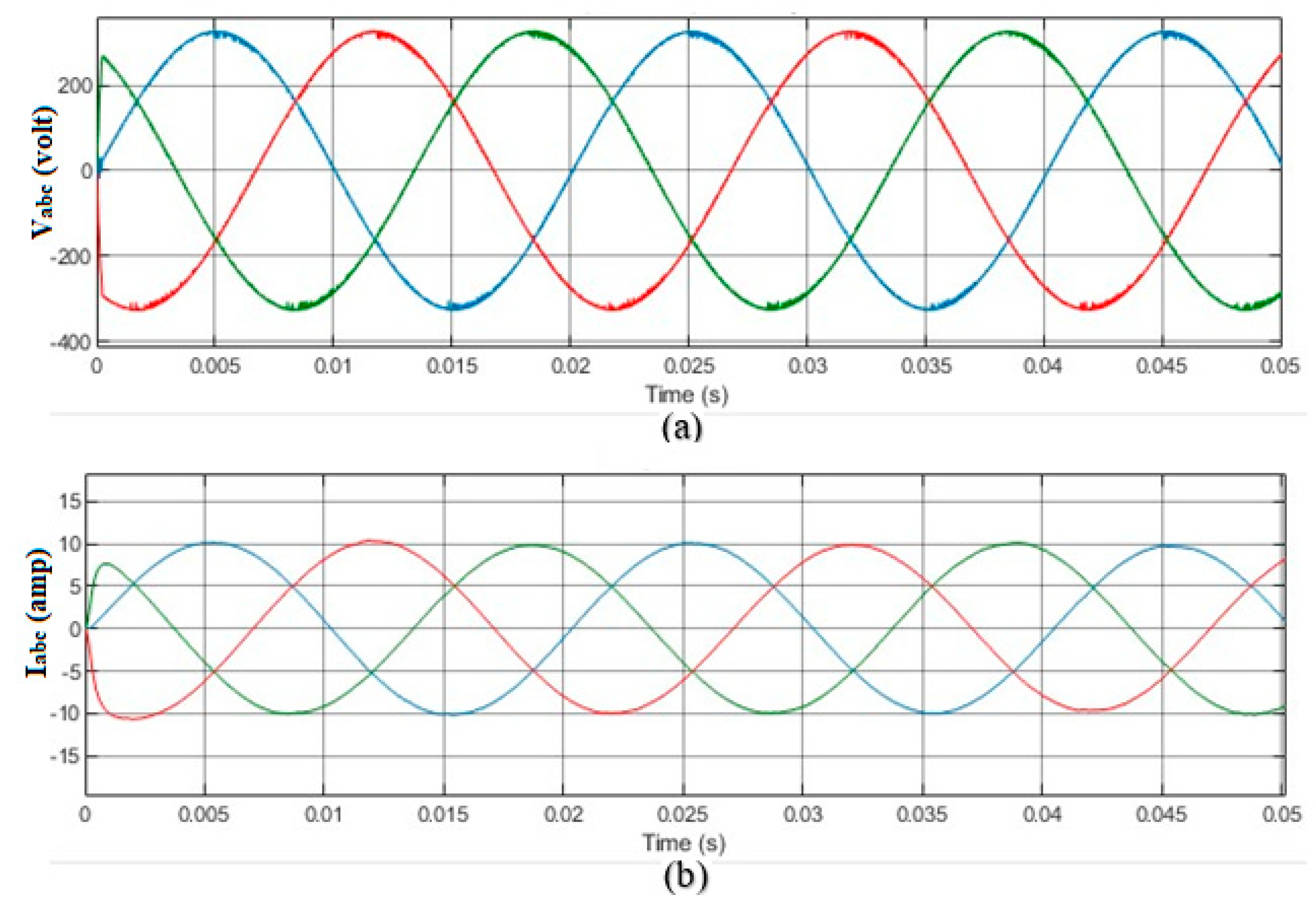
5. Experimental Results and Discussion

To evaluate the practicality of the proposed study, an experimental MG was constructed, as seen in Figure 9. The configuration’s characteristics are detailed in Table 2. The experimental configuration and electrical schematic comprise three DG interconnected through impedance, voltage, and current proportional resonant, LCL filters, and a MATLAB (R2022a) Simulink environment for the implementation of the power system under study and suggested control approach based on dragonfly algorithms. The optimization algorithm DA is executed within a script (m. file). This script file is linked to the Simulink environment in order to evaluate the cost function. In the context of DA, the population size, which refers to the search agent number, is set to 50. Additionally, the number of iterations is adjusted to 40. The optimization process utilizing DA is iterated 35 times for each model, and the ultimate optimal solution obtained from the 35 runs is established as the gain value of the controller employed in the simulations. The communication topology utilizing the adjacency matrix is depicted in Figure 8. Figure 10a,b depict output voltage and current waveform while a DG system is providing power to a nonlinear load. The system response figure consists of three lines, where the blue color refers to D G 1 , the red color refers to D G 2 , and the green color refers to D G 3 . Also, the centralized secondary control configuration with PR droop controller is simulated for the same case study in order to compare it with the proposed SDCC behavior and to evaluate the power system performance.
Remark 1.
(Different load conditions). In order to evaluate the effectiveness of the proposed control system, it is crucial to recognize the inherent variability in load conditions across different scenarios within the scope of this study.

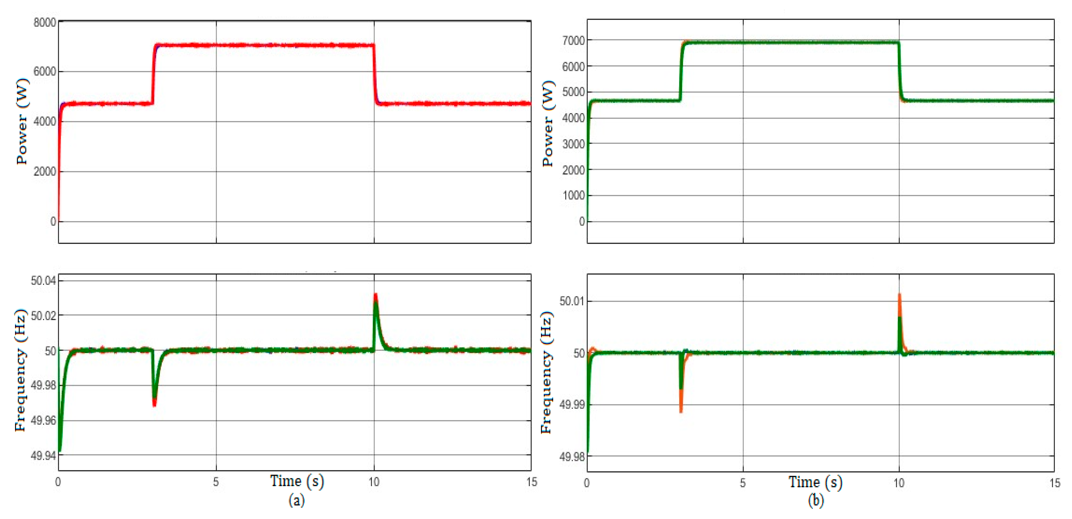
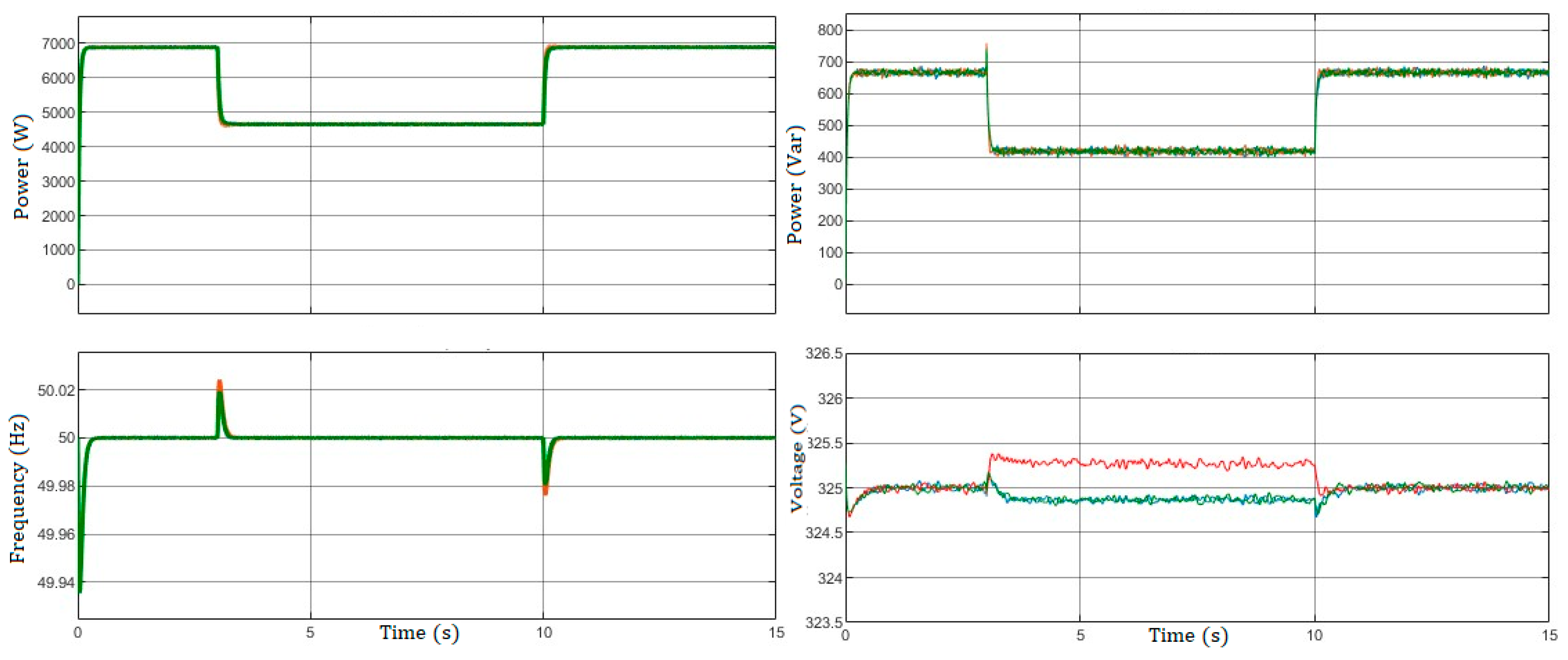
5.1. Active Power and Frequency Evaluation

Figure 11 illustrates the MG transient response under continuous operation of the secondary control. The constant loads are being operated at D G 1 and D G 3 , while the additional local load at D G 2 is introduced at t = 3 s and subsequently disconnected at t = 10 s. It should be noted that the frequency is restored in both instances. The MG, being a compact power electronics-based technology, exhibits a quicker response compared to typical centralized techniques. The observed phenomenon is characterized by a gradual return to the expected frequency and amplitude. By analyzing the frequency dynamics shown in Figure 11, the frequency variation encountered under primary droop control is swiftly mitigated by the SDCC approach that is detailed in Section 4 of this research article. Consequently, the SDCC controller effectively ensures consistent frequency regulation during load variations while minimizing any transient effects.
The active power is effectively distributed across the diverse distributed generators (DGs) over the entire duration of operation. The consistent frequency and active power characteristics observed in all previous sub-studies led us to exclude the plots from our presentation due to limited space.

5.2. Reactive Power and Voltage Evaluation

This study presents a novel control method that aims to simultaneously tackle the complex objectives of reactive power sharing and voltage management, which are commonly perceived as conflicting objectives in power distribution systems. In this study, we investigate a particular case whereby the control system successfully achieves the optimal allocation of reactive power. However, it has difficulties maintaining voltage regulation. However, the results of our study indicate that the suggested control method maintains an acceptable and dependable response, even in situations where voltage regulation is not perfect. The subsequent analyses shown in Figure 12 and Figure 13 serve to underscore the findings discussed in Section 3.1 and Section 3.2 pertaining to the constraints associated with voltage secondary control.

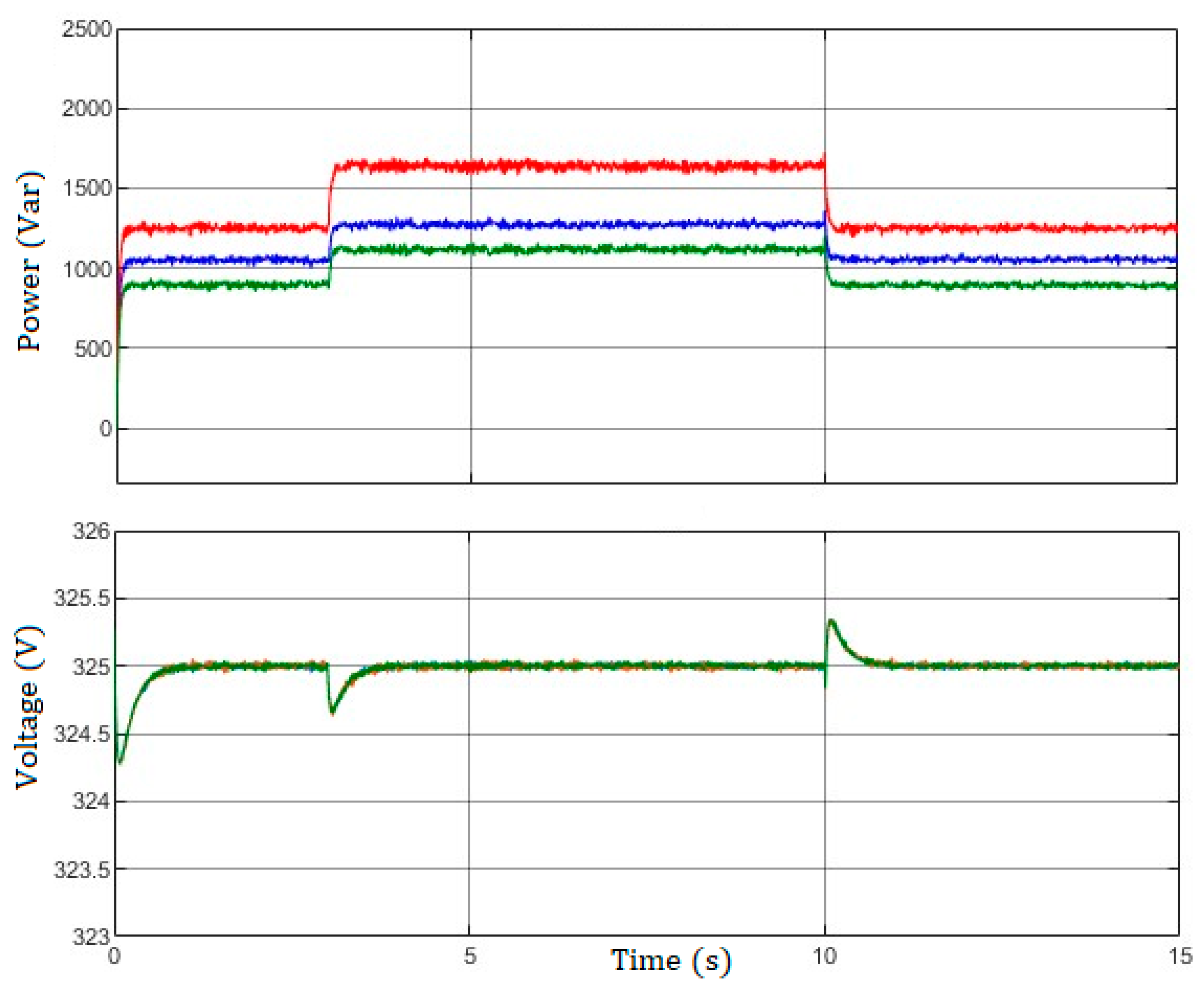
5.2.1. Adjusting for the Equitable Regulation of Voltage

The findings depicted in Figure 12 present the outcomes obtained by employing the identical controller configuration, which was adjusted to maintain voltage levels while disregarding the sharing of reactive power (with β p a ,   β i a   = 0). Although the regulation of voltage levels is stringent, as in Section 3.1, the sharing of reactive power among the units is unsatisfactory. In this case study, three constant loads are operated at the start of the simulation, and another load is added at unit 2 at t = 3 s and disconnected at t = 10 s.

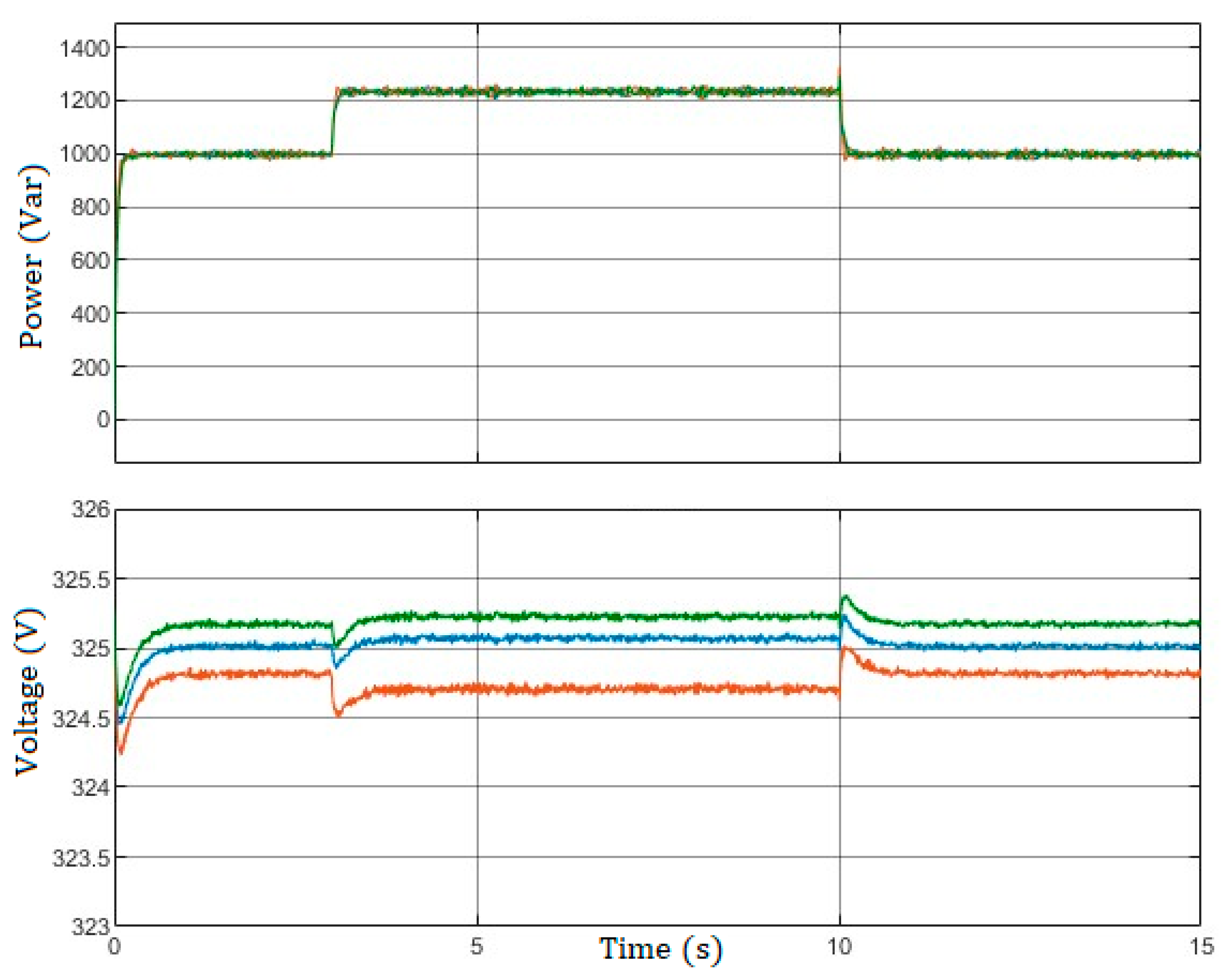
5.2.2. Adjusting for the Equitable Distribution of Reactive Power

The examined situation, in which the coexistence of optimal reactive power sharing and inefficient voltage control is addressed, highlights the flexibility and resilience of the technique we suggest. In this scenario, the control system places emphasis on the effective distribution of reactive power resources among different components of the grid, therefore guaranteeing the prompt availability of reactive power in areas where it is most required. In contrast, Figure 13 illustrates the outcomes obtained from the implementation of the suggested SDCC controller, which has been fine-tuned to facilitate power sharing (with α p a ,   α i a = 0), without including any measures for voltage regulation, as in Section 3.2. Although the sharing of reactive power is precise, there is a deviation in the voltage magnitudes from their nominal values, denoted as E * = 325.2 V.
Remark 2.
Notwithstanding the acknowledged difficulties in voltage regulation, our study results indicate that the reaction of the control system remains satisfactory and dependable. The flexibility and robustness of the system are demonstrated, as it effectively mitigates voltage fluctuations, ensuring that they remain within acceptable limits.

5.2.3. Balancing Voltage and Reactive Power for Optimal Equity

By carefully changing certain parameters, our study showed that there is a clear trade-off between controlling voltage and allocating reactive power. This shows that the system is good at handling these competing goals in power distribution networks. Figure 14 illustrates the process of the synchronization between the grid and DGs unit, specifically in terms of V and Q . It is evident that the MG voltage is regulated in close proximity to the nominal value, exhibiting very finite oscillation and displaying a decreasing discrepancy between them. The findings of this study indicate that the implementation of the cooperative SDCC algorithm does not have a significant impact on system stability. In terms of how voltage changes over time, the voltage SDCC controller finds a good balance and fair compromise between V and Q . The magnitudes of voltage tend to form clusters around a value of E * = 325.2V, although the distribution of reactive power is very evenly distributed. As in ( f and P ) response evaluation, the constant loads are being operated at D G 1 and D G 3 , while the additional local load at D G 2 is introduced at t = 3 s and subsequently disconnected at t = 10 s.

5.3. Communication Connection Failure

In the present investigation, it is seen that the communication link (as depicted in communication topology Figure 8) connecting DG units 2 and 3 experiences a failure at time t = 2 s. In this scenario, the three DGs are uploaded at first, and at time t = 3 s, the local load connected to unit 2 becomes disconnected and is subsequently reconnected at time t = 10 s. According to the findings depicted in Figure 15, the SDCC controllers demonstrate consistent high performance, even in the event of the lack of the communication link across D G 2 and D G 3 .

5.4. Plug and Play Study

The functionality of the controllers’ plug/play feature was assessed by a test in which unit 3 was open at t = 3 s, and subsequently at t = 6 s is reattached. The findings are presented in Figure 16. Similar to earlier trials, the SDCC controllers effectively maintain precise power distribution, as well as frequency and voltage regulation, Prior to, during, and following the connection/disconnection process, while exhibiting minimal transitory effects. Despite the disconnection of D G 3 , the bus frequencies and voltages remain adequately regulated.
Remark 3.
In the present scenario, individual DGs are exposed to different load values that differ from the load values in the respective scenarios. This serves the purpose of verifying the effectiveness of the suggested control system during the play/plug test, hence guaranteeing the divergence of load values among the DGs.

6. Conclusions

A novel approach SDCC has been proposed for the implementation of secondary control in island MGs, utilizing a broad stochastic distribution methodology. The proposed system is implemented by integrating proportional resonant and virtual impedance droop control in the stationary reference frames, together with intelligent distributed averaging SC optimized by the DA. As shown in the system performance section of the results section, SDCC controllers have successfully achieved frequency regulation and proportional active and reactive power sharing under several scenarios with conflicting goals of optimal reactive power allocation and voltage management. Therefore, SDCC facilitated a quick restoration to steady-state operations. DA demonstrates effectiveness in solving multi-objective optimization challenges in practical power systems, supported by empirical evidence and performance metrics. Its ability to enhance the initial random population contributes to competitive outcomes compared to established algorithms. The algorithm’s empirical findings reveal precise approximations of optimal solutions, showing promise for complex multi-objective optimization in real-world power systems. Future research may expand the study’s scope, incorporating more buses and control variables for broader applicability in MG distribution systems.

Author Contributions

Methodology, F.N.S.A.-d.; software, F.N.S.A.-d.; validation, F.N.S.A.-d.; formal analysis, F.N.S.A.-d.; investigation, F.N.S.A.-d.; writing—original draft preparation, F.N.S.A.-d.; review and editing, S.K.; supervision, S.K. All authors have read and agreed to the published version of the manuscript.

Funding

This research received no external funding.

Data Availability Statement

Data available on request due to privacy restrictions.

Conflicts of Interest

The authors declare no conflict of interest.

References

  1. Zolfaghari, M.; Gharehpetian, G.B.; Shafie-khah, M.; Catalão, J.P.S. Comprehensive review on the strategies for controlling the interconnection of AC and DC microgrids. Int. J. Electr. Power Energy Syst. 2022, 136, 107742. [Google Scholar] [CrossRef]
  2. Morstyn, T.; Hredzak, B.; Agelidis, V.G. Control Strategies for Microgrids with Distributed Energy Storage Systems: An Overview. IEEE Trans. Smart Grid 2018, 9, 3652–3666. [Google Scholar] [CrossRef]
  3. Guerrero, J.M.; Vasquez, J.C.; Matas, J.; de Vicuna, L.G.; Castilla, M. Hierarchical Control of Droop-Controlled AC and DC Microgrids—A General Approach Toward Standardization. IEEE Trans. Ind. Electron. 2011, 58, 158–172. [Google Scholar] [CrossRef]
  4. Dehkordi, N.M.; Khorsandi, A.; Baghaee, H.R.; Sadati, N.; Moghaddam, S.S.; Guerrero, J.M. Voltage and Frequency Consensusability of Autonomous Microgrids Over Fading Channels. IEEE Trans. Energy Convers. 2021, 36, 149–158. [Google Scholar] [CrossRef]
  5. Khayat, Y.; Shafiee, Q.; Heydari, R.; Naderi, M.; Dragicevic, T.; Simpson-Porco, J.W.; Dorfler, F.; Fathi, M.; Blaabjerg, F.; Guerrero, J.M.; et al. On the Secondary Control Architectures of AC Microgrids: An Overview. IEEE Trans. Power Electron. 2020, 35, 6482–6500. [Google Scholar] [CrossRef]
  6. Saeed, A.T.; Taha, M.Q.; Ahmed, A.K. Tracking technique for the sudden change of PV inverter load. Int. J. Power Electron. Drive Syst. 2019, 10, 2076–2083. [Google Scholar] [CrossRef]
  7. Zhang, Z.; Babayomi, O.; Dragicevic, T.; Heydari, R.; Garcia, C.; Rodriguez, J.; Kennel, R. Advances and opportunities in the model predictive control of microgrids: Part I–primary layer. Int. J. Electr. Power Energy Syst. 2022, 134, 107411. [Google Scholar] [CrossRef]
  8. Shan, Y.; Ma, L.; Yu, X. Hierarchical Control and Economic Optimization of Microgrids Considering the Randomness of Power Generation and Load Demand. Energies 2023, 16, 5503. [Google Scholar] [CrossRef]
  9. Micallef, A.; Apap, M.; Spiteri-Staines, C.; Guerrero, J.M.; Vasquez, J.C. Reactive Power Sharing and Voltage Harmonic Distortion Compensation of Droop Controlled Single Phase Islanded Microgrids. IEEE Trans. Smart Grid 2014, 5, 1149–1158. [Google Scholar] [CrossRef]
  10. Javed, H.; Muqeet, H.A.; Shehzad, M.; Jamil, M.; Khan, A.A.; Guerrero, J.M. Optimal Energy Management of a Campus Microgrid Considering Financial and Economic Analysis with Demand Response Strategies. Energies 2021, 14, 8501. [Google Scholar] [CrossRef]
  11. Vinothine, S.; Widanagama Arachchige, L.N.; Rajapakse, A.D.; Kaluthanthrige, R. Microgrid Energy Management and Methods for Managing Forecast Uncertainties. Energies 2022, 15, 8525. [Google Scholar] [CrossRef]
  12. Li, Z.; Cheng, Z.; Liang, J.; Si, J.; Dong, L.; Li, S. Distributed Event-Triggered Secondary Control for Economic Dispatch and Frequency Restoration Control of Droop-Controlled AC Microgrids. IEEE Trans. Sustain. Energy 2020, 11, 1938–1950. [Google Scholar] [CrossRef]
  13. Ding, L.; Han, Q.-L.; Zhang, X.-M. Distributed Secondary Control for Active Power Sharing and Frequency Regulation in Islanded Microgrids Using an Event-Triggered Communication Mechanism. IEEE Trans. Ind. Inform. 2019, 15, 3910–3922. [Google Scholar] [CrossRef]
  14. Sun, W.; Fang, Z.; Huang, L.; Li, Q.; Li, W.; Xu, X. Distributed robust secondary control of islanded microgrid with stochastic time-varying delays and external disturbances. Int. J. Electr. Power Energy Syst. 2022, 143, 108448. [Google Scholar] [CrossRef]
  15. Che, L.; Liu, X.; Li, Z.; Wen, Y. False Data Injection Attacks Induced Sequential Outages in Power Systems. IEEE Trans. Power Syst. 2019, 34, 1513–1523. [Google Scholar] [CrossRef]
  16. Peng, C.; Sun, H.; Yang, M.; Wang, Y.-L. A Survey on Security Communication and Control for Smart Grids Under Malicious Cyber Attacks. IEEE Trans. Syst. Man Cybern. Syst. 2019, 49, 1554–1569. [Google Scholar] [CrossRef]
  17. Yu, L.; Shi, D.; Xu, G.; Guo, X.; Jiang, Z.; Jing, C. Consensus Control of Distributed Energy Resources in a Multi-Bus Microgrid for Reactive Power Sharing and Voltage Control. Energies 2018, 11, 2710. [Google Scholar] [CrossRef]
  18. Dong, J.; Gong, C.; Bao, J.; Zhu, L.; Hou, Y.; Wang, Z. Secondary-Frequency and Voltage-Regulation Control of Multi-Parallel Inverter Microgrid System. Energies 2022, 15, 8533. [Google Scholar] [CrossRef]
  19. Khayat, Y.; Naderi, M.; Shafiee, Q.; Batmani, Y.; Fathi, M.; Guerrero, J.M.; Bevrani, H. Decentralized Optimal Frequency Control in Autonomous Microgrids. IEEE Trans. Power Syst. 2019, 34, 2345–2353. [Google Scholar] [CrossRef]
  20. Lou, G.; Gu, W.; Wang, L.; Xu, B.; Wu, M.; Sheng, W. Decentralized secondary voltage and frequency control scheme for islanded microgrid based on adaptive state estimator. IET Gener. Transmiss. Distrib. 2017, 11, 3683–3693. [Google Scholar] [CrossRef]
  21. Malek, H.; Dadras, S.; Yin, C.; Chen, Y. Fractional Order Proportional-Resonant Controller. In Proceedings of the 2018 Annual American Control Conference (ACC), Milwaukee, WI, USA, 27–29 June 2018; pp. 3086–3091. [Google Scholar]
  22. Heydari, R.; Dragicevic, T.; Blaabjerg, F. High-bandwidth secondary voltage and frequency control of VSC-based AC microgrid. IEEE Trans. Power Electron. 2019, 34, 11320–11331. [Google Scholar] [CrossRef]
  23. Zhang, Y.; Shotorbani, A.M.; Wang, L.; Mohammadi-Ivatloo, B. Distributed secondary control of a microgrid with a generalized pi finite-time controller. IEEE Open Access J. Power Energy 2021, 8, 57–67. [Google Scholar] [CrossRef]
  24. Shan, Y.; Hu, J.; Chan, K.W.; Islam, S. A Unified Model Predictive Voltage and Current Control for Microgrids with Distributed Fuzzy Cooperative Secondary Control. IEEE Trans. Ind. Inform. 2021, 17, 8024–8034. [Google Scholar] [CrossRef]
  25. Xu, Y.; Sun, H.; Gu, W.; Xu, Y.; Li, Z. Optimal distributed control for secondary frequency and voltage regulation in an islanded microgrid. IEEE Trans. Ind. Inform. 2019, 15, 225–235. [Google Scholar] [CrossRef]
  26. Sharbafi, M.A.; Lucas, C.; Daneshvar, R. Motion Control of Omni-Directional Three-Wheel Robots by Brain-Emotional-Learning-Based Intelligent Controller. IEEE Trans. Syst. Man Cybern. Part C Appl. Rev. 2010, 40, 630–638. [Google Scholar] [CrossRef]
  27. Mirjalili, S. Dragonfly algorithm: A new meta-heuristic optimization technique for solving single-objective, discrete, and multi-objective problems. Neural Comput. Appl. 2016, 27, 1053–1073. [Google Scholar] [CrossRef]
  28. Asadi, Y.; Eskandari, M.; Mansouri, M.; Savkin, A.V.; Pathan, E. Frequency and Voltage Control Techniques through Inverter-Interfaced Distributed Energy Resources in Microgrids: A Review. Energies 2022, 15, 8580. [Google Scholar] [CrossRef]
  29. Heiba, B.; Yahya, A.M.; Taha, M.Q.; Khezam, N.; Mahmoud, A.K. Performance analysis of 30MW wind power plant in an operation mode in Nouakchott, Mauritania. Int. J. Power Electron. Drive Syst. 2021, 12, 532–541. [Google Scholar]
  30. Yang, Y.H.; Deng, C.; Xie, X.; Ding, L. Distributed Resilient Secondary Control for AC Microgrid Under FDI Attacks. IEEE Trans. Circuits Syst. II Express Briefs 2023, 70, 2570–2574. [Google Scholar] [CrossRef]
  31. Simpson-Porco, J.W.; Shafiee, Q.; Dörfler, F.; Vasquez, J.C.; Guerrero, J.M.; Bullo, F. Secondary Frequency and Voltage Control of Islanded Microgrids via Distributed Averaging. IEEE Trans. Ind. Electron. 2015, 62, 7025–7038. [Google Scholar] [CrossRef]
  32. Alkhafaji, A.S.; Trabelsi, H. Uses of Superconducting Magnetic Energy Storage Systems in Microgrids under Unbalanced Inductive Loads and Partial Shading Conditions. Energies 2022, 15, 8597. [Google Scholar] [CrossRef]
  33. Saeed, F.N.; Sultan, A.J. Hybrid PID-Fuzzy Controller for AGC in Two Thermal Area. J. Eng. Appl. Sci. 2018, 13, 9245–9251. [Google Scholar]
  34. Taha, M.Q.; Lpizra, M.A. Design a new PWM switching technique in multilevel converters. In Proceedings of the 2016 Annual Connecticut Conference on Industrial Electronics, Technology and Automation (CT-IETA), Bridgeport, CT, USA, 14 October 2016; pp. 1–4. [Google Scholar]
  35. Tayab, U.B.; Roslan, M.A.B.; Hwai, L.J.; Kashif, M. A review of droop control techniques for microgrid. Renew. Sustain. Energy Rev. 2017, 76, 717–727. [Google Scholar] [CrossRef]
  36. Rajanna, B.V.; Rao, G.J.; Shrivastava, S.K. Defining control strategies for micro grids islanded operation with maximum power point tracking using a fuzzy logic control scheme. Int. J. Power Electron. Drive Syst. 2016, 7, 723–733. [Google Scholar] [CrossRef]
  37. Vasquez, E.J.C.; Guerrero, J.M.; Savaghebi, M.; Eloy-Garcia, J.; Teodorescu, R. Modeling, Analysis, and Design of Stationary-Reference-Frame Droop-Controlled Parallel Three-Phase Voltage Source Inverters. IEEE Trans. Ind. Electron. 2013, 60, 1271–1280. [Google Scholar] [CrossRef]
  38. Li, Q.; Peng, C.; Chen, M.; Chen, F.; Kang, W.; Guerrero, J.M.; Abbott, D. Networked and Distributed Control Method with Optimal Power Dispatch for Islanded Microgrids. IEEE Trans. Ind. Electron. 2017, 64, 493–504. [Google Scholar] [CrossRef]
  39. Ferreira, D.; Silva, S.; Silva, W.; Brandao, D.; Bergna, G.; Tedeschi, E. Overview of Consensus Protocol and Its Application to Microgrid Control. Energies 2022, 15, 8536. [Google Scholar] [CrossRef]
  40. Mohammed, M.K.; Taha, M.Q.; Salih, F.F.; Saeed, F.N. Optimization and fault diagnosis of 132 kV substation low-voltage system using electrical transient analyzer program. Int. J. Electr. Comput. Eng. 2023, 13, 2375–2383. [Google Scholar] [CrossRef]
  41. Çelik, E. Design of new fractional order PI–fractional order PD cascade controller through dragonfly search algorithm for advanced load frequency control of power systems. Soft Comput. 2021, 25, 1193–1217. [Google Scholar] [CrossRef]
Figure 1. Diagram of architecture of MG control with DGs.
Energies 16 07675 g001
Figure 2. Primary and secondary responses: (a) frequency control, (b) voltage regulation.
Energies 16 07675 g002
Figure 3. Communication topology and adjacency matrix for four DGs, with ν = {1, 2, 3, 4}.
Energies 16 07675 g003
Figure 4. Q-E compromising problem: (a) parallel inverter scheme, (b) Q-E sharing.
Energies 16 07675 g004
Figure 5. Q-E standard SC (a) without power sharing, (b) with power sharing [31].
Energies 16 07675 g005
Figure 6. PR control implementation.
Energies 16 07675 g006
Figure 7. PR virtual impedance block diagram of the droop controller in αβ-frames.
Energies 16 07675 g007
Figure 8. The proposed SDCC control system block diagram.
Energies 16 07675 g008
Figure 9. Experimental setup scheme.
Energies 16 07675 g009
Figure 10. Three-phase system response: (a) output voltage, (b) output current waveform.
Energies 16 07675 g010
Figure 11. f deviation and P sharing: (a) centralized technique, (b) proposed SDCC.
Energies 16 07675 g011
Figure 12. Poor Q sharing and accurate V regulation.
Energies 16 07675 g012
Figure 13. Degree acceptable of V regulation and accurate Q sharing.
Energies 16 07675 g013
Figure 14. Compromise between V regulation and Q sharing: (a) centralized technique, (b) proposed SDCC.
Energies 16 07675 g014
Figure 15. Proposed SDCC performance under communication failure scenario.
Energies 16 07675 g015
Figure 16. Proposed SDCC performance under play and plug scenario.
Energies 16 07675 g016
Table 1. (E and Q) relationships for primary and secondary control actions.
Control Level E Q
Primary E * > E 1 > E 2 Q 2 > Q 1
Secondary (s) E * = E 1 s = E 2 s Q 2 s > Q 2 > Q 1 > Q 1 s
Power sharing (“)- Q 1 = Q 2
Table 2. System parameters.
ParameterSymbolValueUnit
System Data
AC voltage V g 325.2V
MG frequency f 50Hz
Filter impedance R 1 0.5 o h m
L 1 5 m H
Output impedance R 2 0.065 o h m
L 2 1 m H
T. line impedance R T L 0.065 o h m
L T L 1 m H
Output inductance C10 μ F
DC voltage V d c 800V
PR controller gains for voltage/current
PR voltage loop K P V α β , K r V α β 10, 0.1
PR current loop K P I α β , K r I α β 10, 0.1
Disclaimer/Publisher’s Note: The statements, opinions and data contained in all publications are solely those of the individual author(s) and contributor(s) and not of MDPI and/or the editor(s). MDPI and/or the editor(s) disclaim responsibility for any injury to people or property resulting from any ideas, methods, instructions or products referred to in the content.

