Article

Impact of Material Solutions and a Passive Sports Hall’s Use on Thermal Comfort

by
Anna Dudzińska
1,*,
Tomasz Kisilewicz
1 and
Ewelina Panasiuk
2
1
Building Design and Building Physics, Faculty of Civil Engineering, Cracow University of Technology, Warszawska 24, 31-155 Kraków, Poland
2
Architecture of Work-Place, Sport and Favor, Faculty of Architecture, Cracow University of Technology, Warszawska 24, 31-155 Kraków, Poland
*
Author to whom correspondence should be addressed.
Energies 2023, 16(23), 7698; https://doi.org/10.3390/en16237698
Submission received: 22 September 2023 / Revised: 14 November 2023 / Accepted: 15 November 2023 / Published: 21 November 2023
(This article belongs to the Section J: Thermal Management)

Abstract

:
High outdoor temperatures and thermal gains due to solar radiation, which penetrates the interior of buildings as the climate warms up, pose a major challenge to maintaining thermal comfort in passive sports facilities. Superbly insulated and airtight envelopes, specific microclimatic requirements and very high user activity can easily lead to overheating and thermal imbalance during summer. This paper focuses on the influence of the varying thermal capacity of external walls and night-time cooling on thermal comfort in a passive sports hall building. Based on experimental studies of the thermal conditions in the building, a model of it was created in Design Builder. Through simulation, the program initially analysed the thermal conditions that arise under different envelope assemblies. Two different ways of cooling the building at night were then analysed: mechanical and natural. The results presented showed that in a well-insulated sports hall with a large volume, the type of wall material alone had only a limited influence on thermal comfort in summer. In contrast, night-time cooling in integration with the accumulation of cold in the building’s structural components had a significant impact on protection against overheating during the summer. The type of envelope material is even more important when night-time air exchange is high. Intensive natural ventilation is associated with the highest number of hours in the comfort range—28.1–32.4% more hours in relation to the variant without night ventilation. The use of mechanical ventilation, operating at night at maximum capacity, will result in an increase in the number of hours with air temperatures in the −0.5 < PMV < +0.5 range by only 14.1–21.3%. The high thermal mass of the envelope, combined with adequate ventilation, reduces the occurrence of very high indoor air temperatures, thus alleviating the nuisance of overheating. The maximum internal air temperature during the day is lower by 2.4–3.3 K, compared to the case when no night ventilation is used. Mechanical ventilation operating at its maximum capacity can reduce the maximum internal temperature by 1.2–1.6 K.

1. Introduction

Due to intensifying global warming, it becomes a significant challenge to ensure indoor thermal comfort in summer conditions [1]. The conscious and rational design of increasingly popular low-energy buildings requires appropriate solutions and the coupling of architectural decisions with the effects of their applications [2,3]. Sports facilities with specific environmental performance requirements, due to low operating temperatures and high physical activity of users, are a particular challenge. The consequence of the stringent requirements and the high insulation and airtightness of the envelope of such facilities is interior overheating during periods with high outdoor temperatures. Anthropogenic climate change is therefore driving the search for design tools to reduce the energy demand of buildings for both heating and cooling. One possibility to passively protect low-energy buildings from overheating and occupant discomfort is to exploit the accumulative properties of the thermal mass of structural materials [4,5,6,7,8].
The thermal capacity of building partitions, defined as the ability of materials to absorb and accumulate thermal energy under varying ambient temperature conditions, is dependent on the specific heat capacity and density of the materials. As the volumetric density of a material increases, the heat storage capacity of a partition built from it increases. The ability of a material to respond to changes in ambient temperature is characterised by a combination of three parameters: λ, ρ and cp, called the thermal diffusivity coefficient or temperature equilibrium coefficient and is calculated according to Formula (1).
a = λ c p × ρ
where:
a—thermal diffusivity coefficient (temperature compensation coefficient),
λ—thermal conductivity coefficient [W/mK],
cp—specific heat capacity, [J/(kg × K)],
ρ—density [kg/m3].
Another quantity that groups the above material coefficients in a slightly different way is the material’s thermal effusivity coefficient [9,10], also known as the material’s thermal activity.
e = λ × ρ × c p
where:
e—effusivity of the material [ W × s 1 2 m 2 × K ],
λ—thermal conductivity coefficient [W/mK],
cp—specific heat capacity, [J/(kg × K)],
ρ—density [kg/m3].
Numerous studies [11,12,13,14,15,16,17,18,19,20,21,22,23,24,25,26] argue that thermal mass significantly contributes to a reduction in heating and cooling loads. From a thermal comfort perspective, materials with a high density and high specific heat capacity are the most desirable. There are claims in the literature that the rational use of thermal mass can reduce the energy demand for heating and cooling by up to 25–30% [27]. However, this is closely dependent on a number of factors including a building’s size, use and location, internal heat gains, the type of ventilation or, finally, the method of shading [28]. Researchers from the University of Toronto, led by M. Gorgolewski [12], carried out a series of simulations of an industrial building. They looked for the relationship between thermal mass, the thermal resistance value R of the external walls and the size of glazed surfaces. They sought to determine the critical value for the thermal resistance coefficient of external walls. There were suggestions that above a certain value of envelope thermal resistance, additional thermal mass is beneficial, while below this value, energy consumption increases, and thermal comfort is disrupted.
Detailed experimental measurements on thermal mass were carried out, among others, at Newcastle University [29]. The conclusions suggested not to rely solely on thermal resistance, as such an approach can result in erroneous expectations and inefficient design. According to the study, a static parameter such as thermal resistance is not sufficient to analyse the impact of diurnal variations in outdoor temperature and thermal mass on indoor thermal conditions. The analysis of the energy efficiency of real buildings cannot therefore, for obvious reasons, be reduced to an assessment of the thermal transmittance U alone, which ignores dynamic climatic changes in the temperate zone [29].
A team from the University of Tampere, Finland [13], carried out a detailed analysis of 28 publications on the importance of thermal mass and, on this basis, the researchers concluded, among other things, that high thermal capacity reduces the need for mechanical cooling during periods of high outdoor temperatures. In addition, the maximum indoor air temperature in a solid building can be 3–6 K lower than in lightweight buildings. The study showed that linking high thermal mass to night ventilation of office buildings can reduce the energy demand for mechanical cooling by up to 50%. It was concluded that the combination of high thermal mass and high airtightness in single-family homes can result in a 20% reduction in energy demand relative to a lightweight counterpart [16].
Using Norwegian climate data, Dokka [11] analysed the effects of night ventilation and active cooling (single-family and office building) on energy consumption and thermal comfort, for different constructions and different occupancy types. The simulation results indicated that a heavy residential building would require approximately 7% less energy for heating compared to a light building. In an office building, the disparity in heating energy requirements was up to 10%, depending on the building design adopted. In addition, it was shown that an actively cooled lightweight building required more than 30% more energy compared to a solid structure. In the case of a passively cooled lightweight building with additional night ventilation, thermal discomfort was recorded during use. The internal temperature exceeded 26 °C for 179 h in a year [11,16].
Golański [30] provides basic principles for the effective use of thermal mass. In addition to basic information on the placement and preferred thickness of thermal mass, the author clearly suggests that thermal mass should be naturally or mechanically cooled at night during the summer [30].
To determine to what extent the structural concrete of partitions stabilises the indoor climate of a building while minimising energy use, Johannesson G., Lieblang P. and Öberg M. [14,15] carried out a number of simulation studies. They analysed the energy balance in residential and office buildings for heavy and lightweight structures, located in various countries, ranging from Sweden to Portugal. The results showed that heavy construction provides a significant energy performance advantage over lightweight structures. A residential building made of heavy concrete required 2–9% less primary energy compared to a lightweight structure. This advantage increased with larger transparent surfaces on the south side. A solid structure with south-facing glazing resulted in lower energy requirements for cooling. In the case of the office building analysed, the resulting reduction in energy for cooling was used as a measure to evaluate the building. The heavier option in this case produced 10–20% better conditions compared to the lighter option.
Researchers from Tsinghua University in Beijing [18] sought to determine model thermophysical properties for the building envelope. Climatic conditions, internal and external heat sources, orientation relative to the cardinal directions, or type of ventilation were considered. The building model analysed, measuring 4.5 × 3.5 × 2.7 m, was located in Beijing, China. The south façade featured glazing measuring 1.2 × 2.4 m. Internal heat gains were estimated at 7.5 W/m2, and air exchange rates at 1 h−1 (closed window) and 5 h−1 (open window) [18,29]. The simulation results indicated that a construction material with an enormous heat capacity of 100 MJ/m3 × K and, at the same time, a thermal conductivity coefficient λ of less than 0.1 W/mK was needed to completely reduce the energy demand for heating and cooling. The currently used insulating building materials are characterised by much lower conductivity values, but the level of the second parameter is not achievable.
With reference to the results presented in the literature, the following question arises: is material thermal storage capacity crucial in shaping thermal comfort in summer in well-insulated passive sports halls? This paper presents the results of research conducted within the framework of a finished doctoral thesis [31] and aims to show that in a very specific, low-energy sports facility with a large volume, the thermal capacity of the walls alone has only a limited effect on reducing discomfort caused by overheating.

2. Materials and Methods

2.1. Passive Sports Hall

Thermal comfort measurements were taken in a sports hall of the University of Agriculture in Krakow, constructed to passive energy standards (Figure 1). The orientation of passive buildings in relation to the cardinal directions, as recommended by The Passive House Institute in Darmstadt, involves placing the longitudinal axis of the building along the east–west direction. However, due to the shape of the plot, the University hall is oriented along the north–south axis. With a floor area of 1776.2 m2, the building has a multi-purpose sports arena with seating for approximately 156 people in total, as well as a changing room and sanitary facilities with associated spaces. The main body of the building is covered by a flat roof with a 2° pitch and has a grade-to-coping height of 10.35 m. The structural layers of the walls consist of 25 cm thick silicate masonry units insulated with 30 cm thick polystyrene panels. The U-value of non-transparent external partitions is 0.1 W/m2K and that of the transparent ones is 0.8 W/m2K. The designer reports that the total solar energy transmittance g for the glazing assemblies used in the building exceeds 60% [32,33].
The eastern orientation of the building’s large glazing, with a total area of 81.9 m2, resulting from the shape of the plot, entails a significant risk of overheating (Figure 2). Solar gains are to be reduced in summer by electrically controlled external shading blinds.
The building has a final energy consumption for heating of approximately 15 kWh/m2/year and a total primary energy consumption of less than 120 kWh/m2/year. The low energy requirements for heating the sports hall are ensured, among other things, by sufficiently thick, high-quality thermal insulation materials and the high airtightness of the building’s envelope n50 = 0.3 h−1. The building is equipped with mechanical ventilation with heat recovery. The recuperators have a maximum heat recovery efficiency of 85%.

2.2. The Criterion for Ensuring Thermal Comfort

Microclimate assessment involves measuring or calculating the magnitude of the basic and derived physical parameters, and then calculating the values of the relevant indicators for comparison with applicable standards [34] in simulation software. For temperate climates, these requirements are given in the European standard PN-EN ISO 7730:2006 [35].
The instrument used to measure the thermal microclimate in the building under analysis was the BABUC A integrated digital meter (Figure 3), which is compliant with the PN-EN 7726 standard [36]. Sensors connected to the central unit measure dry and wet bulb temperatures, indirectly mean radiant temperature, as well as relative humidity and air velocity.
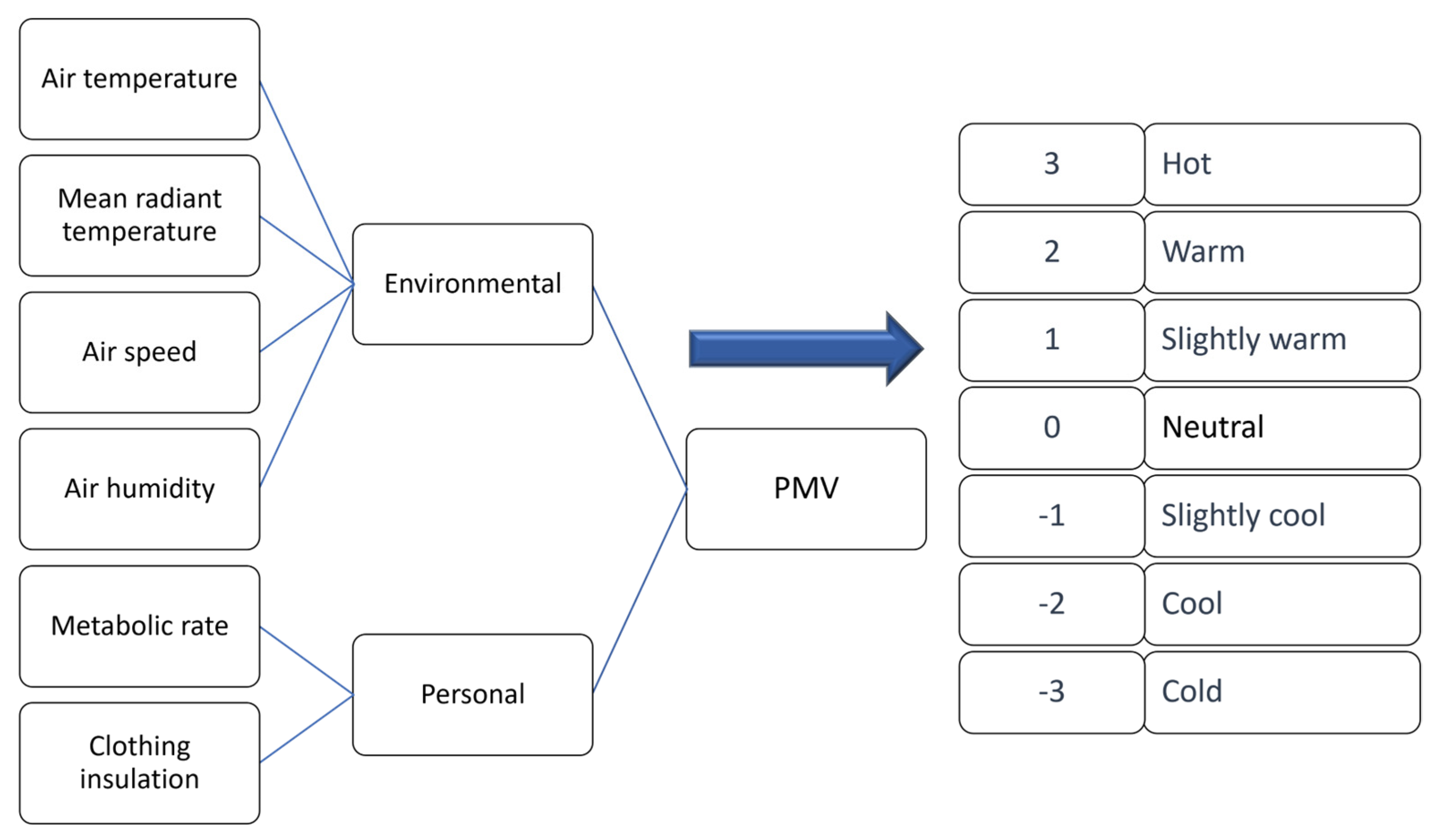
The basic indicators used to analyse the thermal environmental conditions in an indoor space are: PMV (Predicted Mean Vote) and PPD (Predicted Percentage of Dissatisfied), first proposed by Fanger [37]. The PMV index determines the predicted mean score according to Fanger’s seven-point psychophysical heat sensation scale [37] and takes into account a number of environmental and individual parameters that affect heat exchange rates (Figure 4).
Environmental parameters include indoor air temperature, humidity and air velocity, as well as mean radiant temperature. Individual factors related to a building’s users, which include physical activity and the thermal insulation of clothing, are extremely important for the perception of environmental conditions.
The second indicator for assessing comfort is the PPD, i.e., the predicted percentage of dissatisfaction. The PPD index, obtained from the PMV index, provides information on thermal discomfort (thermal dissatisfaction) by predicting the percentage of people likely to feel too hot or too cold in the given thermal environment. Under thermal comfort conditions, for a class with medium requirements (category II according to EN 16798-1 [38]), the PMV should be between −0.5 and +0.5, which corresponds to a PPD value of 10%.

2.3. Simulation Model in Design Builder

In this study, Design Builder software 5.0.3.7 was used to simulate the effects of internal and external shading on thermal conditions in the sports hall. It is worth emphasizing that at present, it is the most modern and most advanced tool designed for simulation calculations.
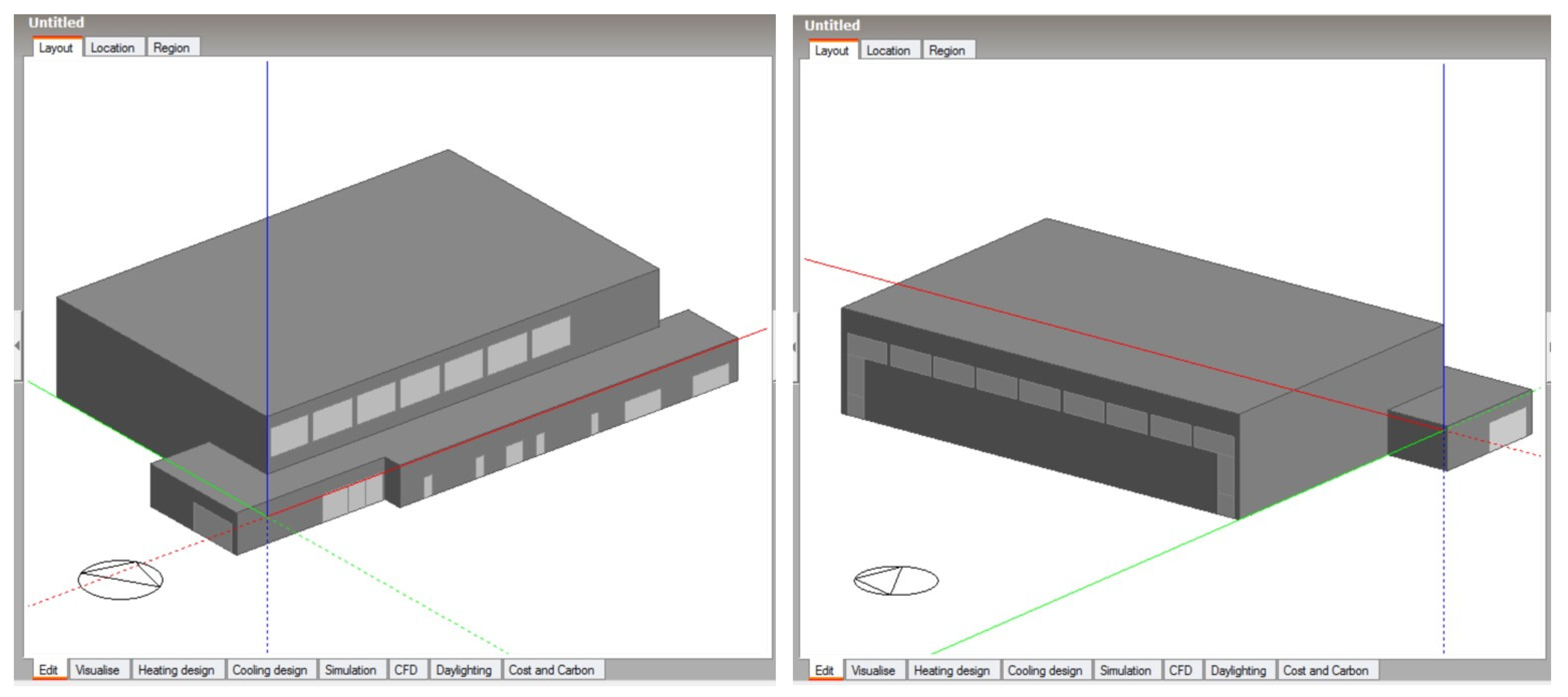
A geometrical solid model of the sports hall under study at the University of Agriculture in Krakow, Figure 5, was created using Design Builder, considering the parameters, structures and MEP services of the facility as well as occupancy schedules.
The hall was designed for 124 spectators and 32 athletes. As the research was performed during the academic year, when the facility is mainly used by student groups, the conditions were analysed in relation to active people only. The exact load on each sector of the sports hall, adopted for the validation of the model and corresponding to the use of the facility during the measurements, is presented in Table 1.
The metabolic energy of the exercising student was assumed to be 300 W/person. The metabolic rate value taken from the Design Builder library corresponds to the activity of a person practicing “exercise/sport”. For the summer period analysed, a clothing thermal resistance value corresponding to lightweight sportswear of 0.3 clo was used.
In the validation, it was assumed, based on the actual use of the hall during the measurements, that the window blinds on the south-east elevation were shut from the early morning hours. Although the blinds were lowered, they did not completely restrict access to light, as the aluminium slats were inclined at approximately 30° to the window surface. On the northwest side, the blinds were not used at all during the measurement period.
The required illuminance in the hall was assumed to be 400 lux as per the relevant standard [39]. Artificial lighting switched on automatically when natural lighting was insufficient during the hall’s opening hours.
A basic simulation algorithm option called Simple was used to model the mechanical ventilation system in Design Builder. In the design documentation of the building, the capacity of the air handling unit was assumed as dependent on use:
  • during a competition and with full stands—100%,
  • 1/3 of the room used—20%,
  • 2 or 3 spectator sectors occupied—40 or 60% of maximum capacity [32].
The maximum capacity of the air handling unit corresponds to an air exchange rate of 0.75 ac/h (maximum ventilation capacity is 9.000 m3/h, room volume is 12.075 m3) [32].
The hall envelope’s high airtightness was confirmed by a pressure test in accordance with EN ISO 13829-2002 [40]. The result was n50 = 0.3 h−1. The model assumed a conventional determination of the airtightness of the sports facility at a level defined as Excellent.
During the validation of the model used for simulation, the effects of air infiltration and natural ventilation were taken into account according to the actual use of the building. An interview was to establish that no fixed schedule for window tilting was in place. It was dependent on subjectively determined needs and individually controlled by class attendees. For the validation of the model, based on the information sought, window opening times were set as shown in Table 2.
The building’s design provided for night-time ventilation, functioning by opening windows on opposite walls of the sports arena. According to the nomenclature adopted by the design’s authors, it was achieved via natural cross-ventilation. However, it is known that this option was not used during the measurement period.
The validation of the hall model was complex and hampered by uncertain information about the use of the facility. The authors were not in the hall for the entire five-day measurement period and the data obtained were based on an interview with hall staff. The original findings, adopted to create the initial model in Design Builder, were at times significantly different from measurements. Only strenuous modifications (about 70 steps), in consultation with the hall staff, regarding the number of hall users and window tilting allowed for a convergence of the data and simulation results.
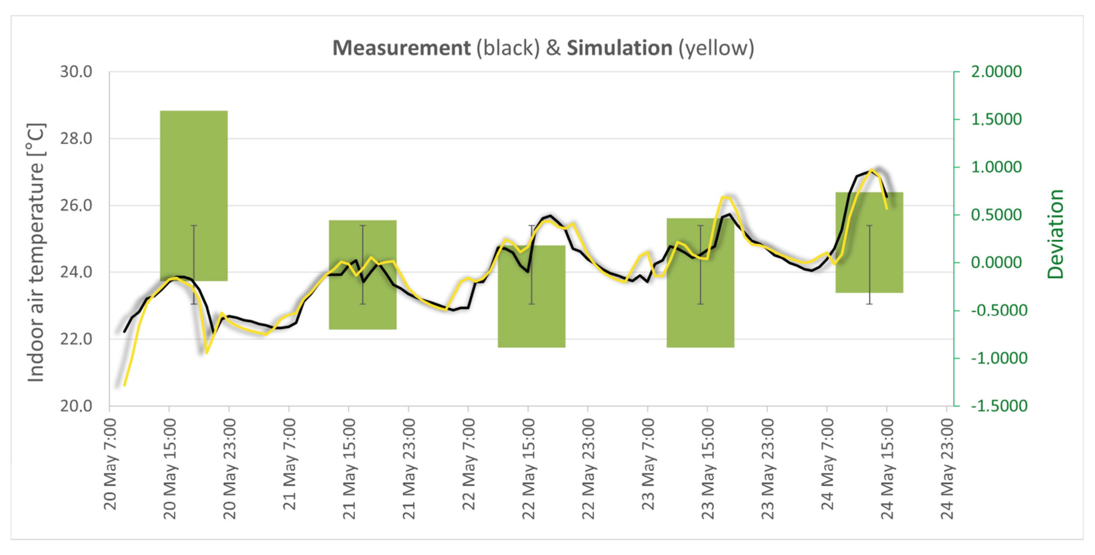
To determine the correlation between the measurements and the simulation, a correlation coefficient was calculated. Comparing the results of indoor air temperature measurements in the hall from 20–24 May with the results of the final model, a correlation coefficient value of 0.94 was obtained (Figure 6).
A correlation coefficient value in the range of 0.7 rxy < 0.9, indicates a very high correlation in statistical analysis [41]. Therefore, the model of the passive sports hall in Krakow made in Design Builder can be used for further analyses.
The standard deviation was calculated, and the differences between the indoor air temperature curves from measurements and simulations were plotted as a bar chart (Figure 6). The resulting standard deviation value of 1.138 indicates a slight dispersion of the variables around the arithmetic mean value of the test variable.

3. Results of Thermal Comfort Analysis

3.1. Experimental Analysis and Survey

The first trial measurements in the facility (without users) were carried out in the period between 7 and 10 August. Another round of measurements was performed the following year between 20 and 24 May, during which the hall was used for sports activities. Each time the outdoor temperature was above 30 °C. The first time, 663 readings were taken over three days, and the second time, 1279 measurements were taken over five days. It should be noted that the facility was not in use during the first series of measurements, so it was possible to carry out continuous tests and leave the measuring equipment unattended and secured in a central area of the arena. The artificial lighting and mechanical ventilation system was switched off during this period and all windows were closed. In this sense, the conditions tested did not correspond to the normal operation of this building, but characterise the natural (undisturbed by the operation of the service) insulating and capacitive properties of the envelope.
The second series of measurements was carried out under conditions compatible with the intended use of the sports facility, which was used throughout the study period. The detailed loading of the individual sectors of the sports hall is given in Table 1.
The mechanical ventilation system was only activated on the second and third days of measurement, i.e., on 21 and 22 May, only when there were people in the hall (Table 1). The windows were opened and closed manually during the tests, during the hours of use of the facility, from 8.00 to 10.00. During the microclimate tests carried out in the hall, the natural night-time ventilation, as assumed in the design, was not used.
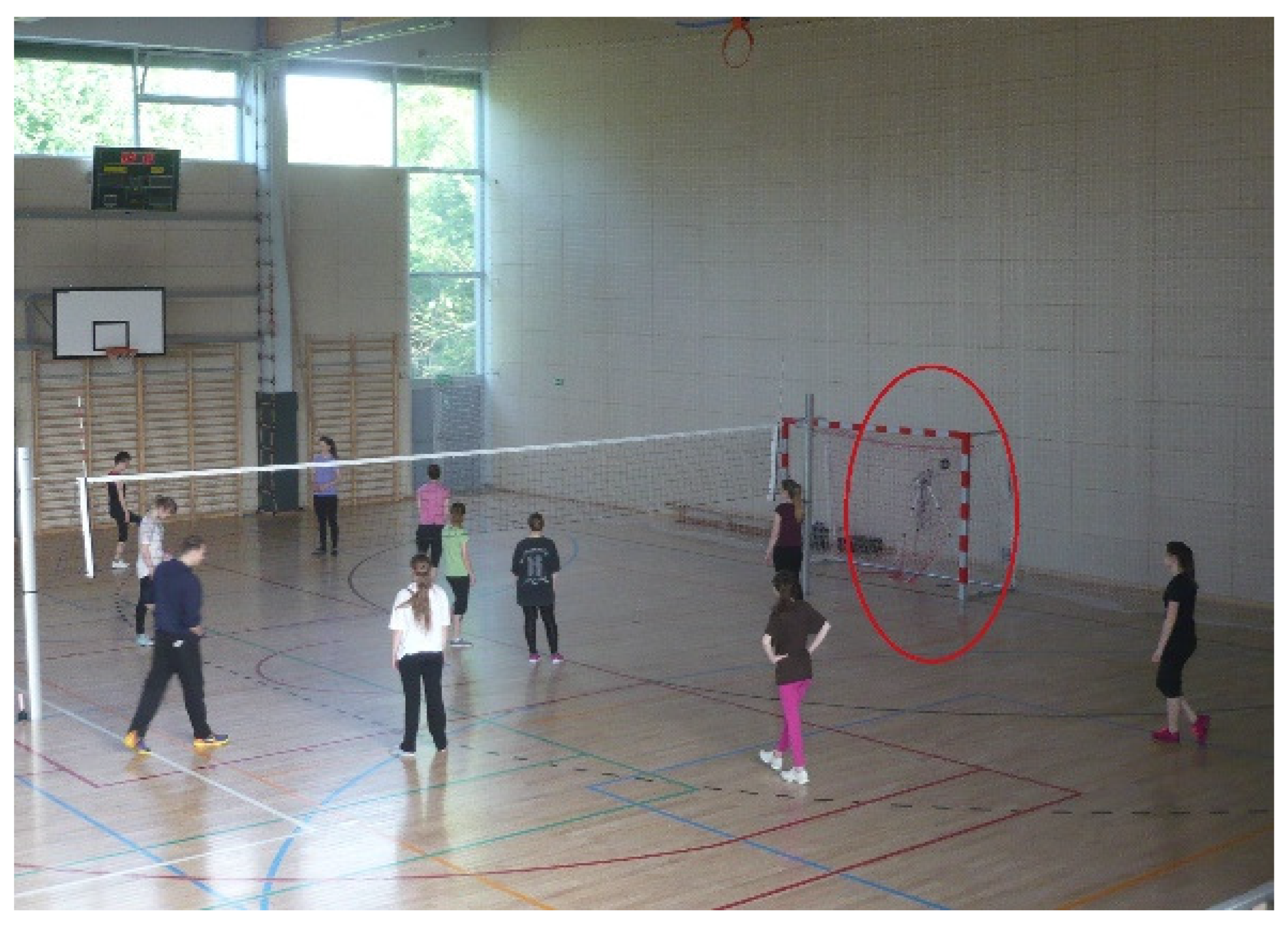
For safety reasons, the meter was located behind a baffle and shielded by a net during the measurements (Figure 7). The short distance from the baffle meant that its effect on the average radiation temperature was overestimated.
Selected indoor environmental parameters for the hall during the study are shown in Table 3.
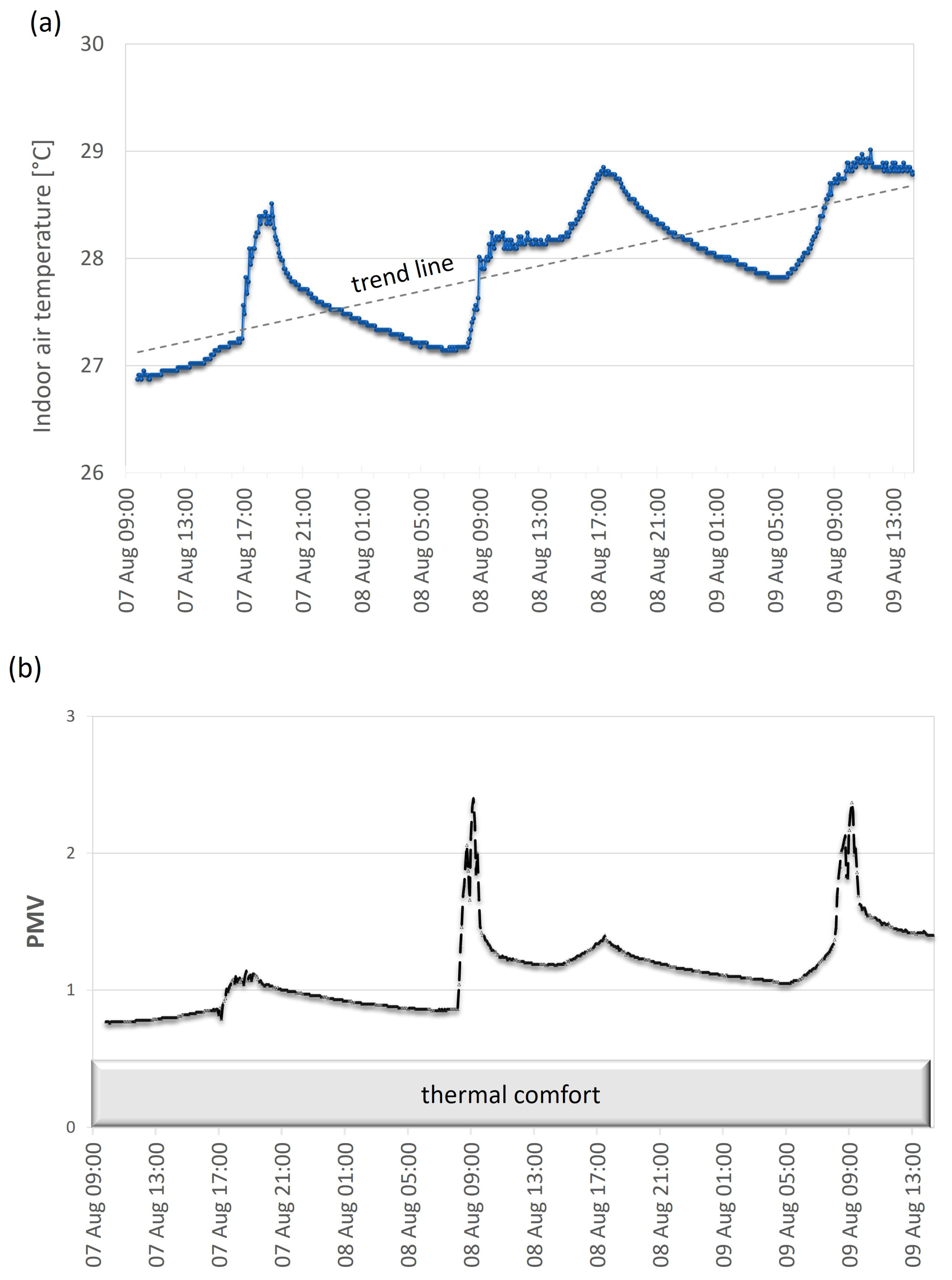
The indoor air temperature ta, during the first measurement period, ranged between 26.9 °C and 29.0 °C, while the average value was 27.9 °C (Table 3). The trend line shown in Figure 8a illustrates the increase in mean indoor air temperature as a result of energy accumulation from day to day. The average value of the radiation temperature of the surrounding surfaces was 28.8 °C, while the average relative indoor air humidity was 58.28% (Table 3).
The mean PMV value (Table 3) was 1.14, but even the minimum value (0.76) was outside the thermal comfort range (Figure 8b). The reason for the observed sudden morning spikes in PMV values (Figure 8b) was the direct solar radiation that reached the meter’s sensors through the unprotected windows on the west side with blinds and the glazing in the emergency door. During the entire monitoring period, the internal thermal conditions were outside the comfort zone. The average PPD value was higher than 30% (Table 3), and the maximum instantaneous value even exceeded 90%.
During the first measurement period, the conditions inside the facility did not produce thermal comfort, not even for a moment. This was not only due to climatic conditions, but also to a large extent to the way the facility was operated during this period. Mechanical ventilation and natural ventilation were not used, and windows were not opened.
During the second series of measurements in May, the average indoor air temperature was 24.1 °C, while the maximum value exceeded 27 °C (Figure 9a). The minimum indoor temperature was 22.1 °C (Figure 9a). Figure 9a, on 21 May, shows a decrease in the indoor temperature (around 16:00–17:00) and a renewed increase from 17:20, related initially to the break in classes and then to the heat load of the hall’s users (Table 1). On 23 May, the indoor air temperature did not increase compared to the previous day, as a result of the lower number of people in the hall in the morning (lower internal gains). In addition, between 12:00 and 16:00, when the hall was not in use, the windows were closed, which protected the building from additional gains from warm outside air. However, it can be seen from the distribution in Figure 9a that the trend line, as before, shows a strong tendency for the temperature values to increase on consecutive days.
On 24 May, during the use of the building by a significant number of people between 9:00 and 15:00, the indoor air temperature rose rapidly, and the highest value was 27.3 °C (Figure 9a). These conditions were influenced by additional heat gains from the outside air, due to the windows on both sides of the space being open all day, and thermal gains from the presence of users. The mean value of the radiation temperature of the surrounding surfaces, however, was significantly lower, at 24.3 °C. The average relative indoor air humidity was 50.85% (Table 3).
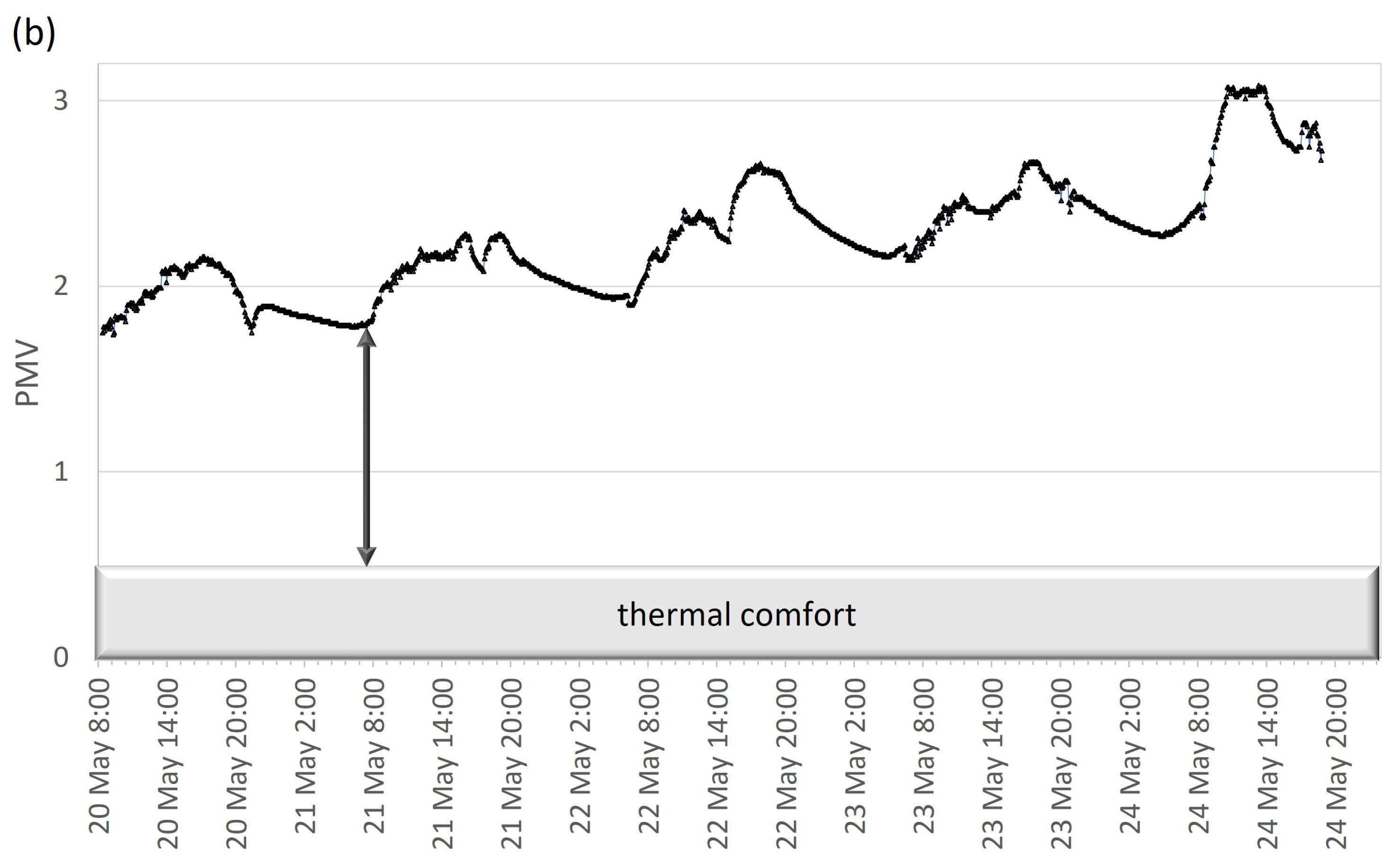
During the entire measurement period in May, internal thermal conditions were far outside the thermal comfort zone (Figure 9b). The PMV value did not fall below 1.6 and its maximum value exceeded 3.0 (Figure 9b). From the third day of the second series of measurements onwards, the PMV value exceeded the permissible value of 2.0 throughout the range.
The unfavourable microclimate in the hall was not only caused by the high outside air temperature, but was also due to the way the building was operated at the time of the measurements. Initially inoperative and then poorly used mechanical ventilation and the lack of regular ventilation at lower outside temperatures led to the accumulation of excess energy in the hall.

3.2. Survey Results

In addition to thermal comfort measurements, an original survey was conducted in the hall among 104 randomly selected users of this building. Essential information about the respondents is shown below:
  • 9 men and 95 women—average physical activity,
  • age of respondents: 19–23 years old,
  • height of the respondents: 160–185 cm,
  • clothing: light, shorts/leggings and t-shirts.
The results of the questionnaire on the environmental conditions inside the hall are presented in Table 4. The majority of the respondents opted for the ‘warmer’ side of the Fanger scale (88/104 of those surveyed). Only 16 of the respondents (15% of those surveyed) described the microclimate in the hall as neutral to them, meaning that they experienced thermal comfort. As many as 30 (28.8%) respondents rated the thermal condition inside the hall as ‘hot’, i.e., the maximum on the scale presented. The ‘warm’ rating was given by 38 people, and the ‘quite warm’ by nearly 20.
The PMV values for both measurement periods were outside the thermal comfort limits. According to international standards and common practice, temporarily exceeded limits are usually accepted provided that the internal microclimate does not endanger the health of the user. The high physical activity of sports hall users, the low insulation value of clothing and the short periods of use preclude the use of an adaptive comfort model. Physiological or psychological adaptation to indoor conditions is impossible if the sports facility is used for several hours a week.
The short-term measurements carried out in the hall and the survey are not sufficient measurements to assess the building. They are an indication that in buildings with very low energy consumption, overheating of the interior often occurs during the summer months. The surveys carried out over a few days are therefore a sufficient basis for confirming the existence of the problem and for further simulation analyses of the studied building.

3.3. Simulation Variants and Results

Due to the specific use of the building only during the academic year, simulations were carried out for the period from 1 May to 30 June. The other summer months were not included due to the holiday period. In the simulation model, the layout of the layers in the external wall assembly was adopted according to the design assumptions: external silicate plaster and adhesive layer reinforced with mesh with a total thickness of 1 cm, thermal insulation—Platinum polystyrene (EPS 031 Termonium Plus) 30 cm, hollow silicate masonry units 25 cm, internal mineral plaster 1 cm [32]. In the subsequent simulation variants, only the structural layer was modified, without changing the other materials. The structural layer thickness of 25 cm assumed in the design was left in place for all options. Although for some variants this assumption deviates far from the actual needs and feasibility, it will allow a simple comparison of the impact of material properties on thermal comfort. The material characteristics are summarised in Table 5.
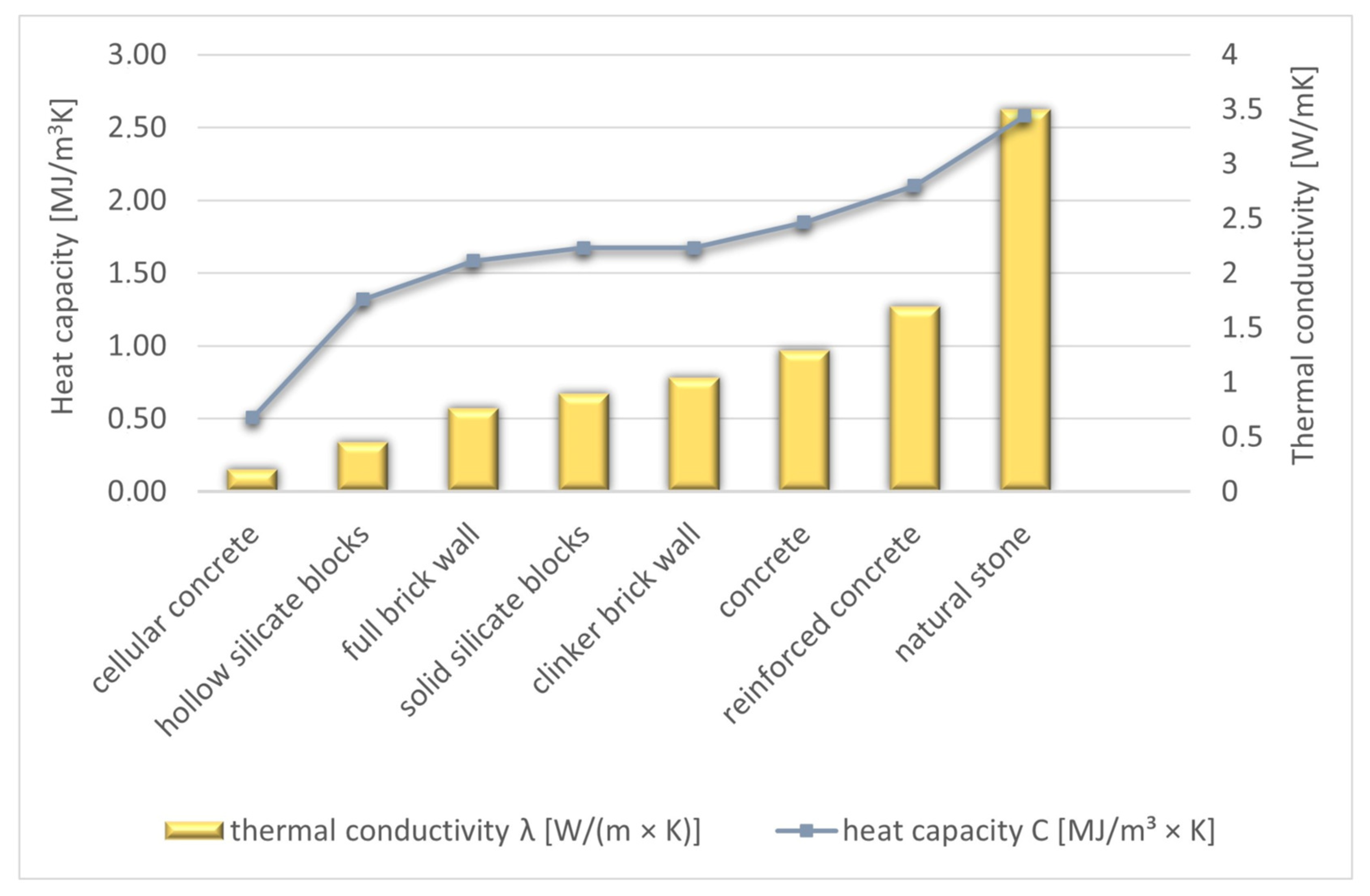
When considering the characteristics of the construction materials adopted for the analysis, it is important to note the values obtained for the temperature equalisation coefficient a. The highest value of the coefficient is found in natural stone (1.36 × 10⁻⁶ m2/s), which has a conductivity coefficient of 3.5 W/mK, Figure 10. This means that a material with a high thermal capacity and conductivity reacts very slowly to fluctuations in external temperature. Reinforced concrete and plain concrete also have relatively high a-values, in contrast to aerated concrete, for example.
In all options for the simulation analysis, the settings (ventilation, lighting, blinds, people) were assumed to be as close as possible to the actual operation of the arena. It was assumed that window opening is possible throughout the day between 8:00 and 22:00 on both sides of the arena (20% of the total opening). In the simulation, however, the daily ventilation was made dependent on the external conditions. If the condition Tout > Tint is met—the windows are closed, where:
  • Tout—outdoor air temperature [°C],
  • Tint—indoor air temperature [°C].
No account was taken of night ventilation, and the assumed minimum indoor air temperature during window tilting is 14 °C. It was assumed that the blinds on the south-east elevation are lowered when the solar irradiance exceeds 100 W/m2, and on the north-west side, the blinds are uncovered throughout the simulation period, which is not in accordance with the design assumptions and common sense, but corresponds to the actual use of the building.
The required illuminance in the hall was assumed to be 400 lux in accordance with PN-EN 124641:2012 [39]. Artificial lighting is used as required during the hours of use of the hall, i.e., 8:00 to 22:00. On the basis of additional simulations it was determined that, despite the lowered blinds on the south-east side in the morning and afternoon, artificial lighting is only needed after 19:00.
The assumed use of the room during the week is shown in Table 6.
The following simulation options were adopted:
  • Variant 1—external wall layering: external silicate plaster and adhesive layer reinforced with 1 cm thick mesh, thermal insulation—polystyrene Platinum 30 cm, plain concrete 25 cm (with parameters as in Table 5), internal mineral plaster 1 cm.
  • Variant 2—aerated concrete in the construction layer with parameters as per Table 5.
  • Variant 3—clinker bricks in the construction layer with parameters as in Table 5.
  • Variant 4—solid bricks in the construction layer with parameters as in Table 5.
  • Variant 5—natural stone in the construction layer with parameters as in Table 5.
  • Variant 6—hollow silicate masonry units in the construction layer with parameters as in Table 5.
  • Variant 7—solid silicate masonry units in the construction layer with parameters as in Table 5.
  • Variant 8—reinforced concrete in the structural layer with parameters as in Table 5.
The Polish building regulations do not provide clear guidance on the temperature range for thermal comfort in sports facilities [33] (Section 4, §134). Regulations specify a design temperature, used in gymnasium design, of 16 °C. However, there are no clear guidelines on the range of thermal comfort for athletes. In publications on thermoregulation, it can be found that, for example, activity at a heart rate of 140–150 beats/min is best performed at 16–17 °C. Increasing the heart rate to 170–180 beats/min is associated with a reduction in the temperature comfort zone to 13–14 °C. In the available sources, there is a lack of clearly defined sports categories, metabolic values and corresponding thermal comfort temperatures. An in-house analysis of indoor conditions for an assumed metabolic level and clothing insulation made it possible to establish (using an algorithm formulated by Fanger) an indoor thermal comfort range. Ultimately, it was assumed that for active users of the hall, comfortable indoor air temperatures in summer are in the range 14–18 °C.
Table 7 summarises the calculated arithmetic mean and maximum values of the indoor air temperature and radiation temperature in the UR hall for the assumed eight simulation variants. The variant with aerated concrete has the highest instantaneous indoor air temperature value of 27.2 °C. In contrast, the lowest maximum temperature of 25.6 °C applies to the structural layer containing natural stone. The average indoor air temperature values for all variants are close to or equal to 19.9 °C. In terms of radiation temperature, the average values for all assumed options are very close to each other and fluctuate around 20.8 °C. Differences in the maximum radiation temperature values are noticeable and amount to 1.3 °C. As with the indoor air temperature, the highest maximum radiant temperature applies to the aerated concrete wall structure (27.0 °C) and the lowest to the natural stone bearing layer (25.3 °C).
The results obtained in this way for a two-month period indicate very little influence of the varying heat capacity of the external walls (for the assumed conditions of use of the building). The differences between the maximum indoor air temperatures are in the range of 0.1–1.6 °K.
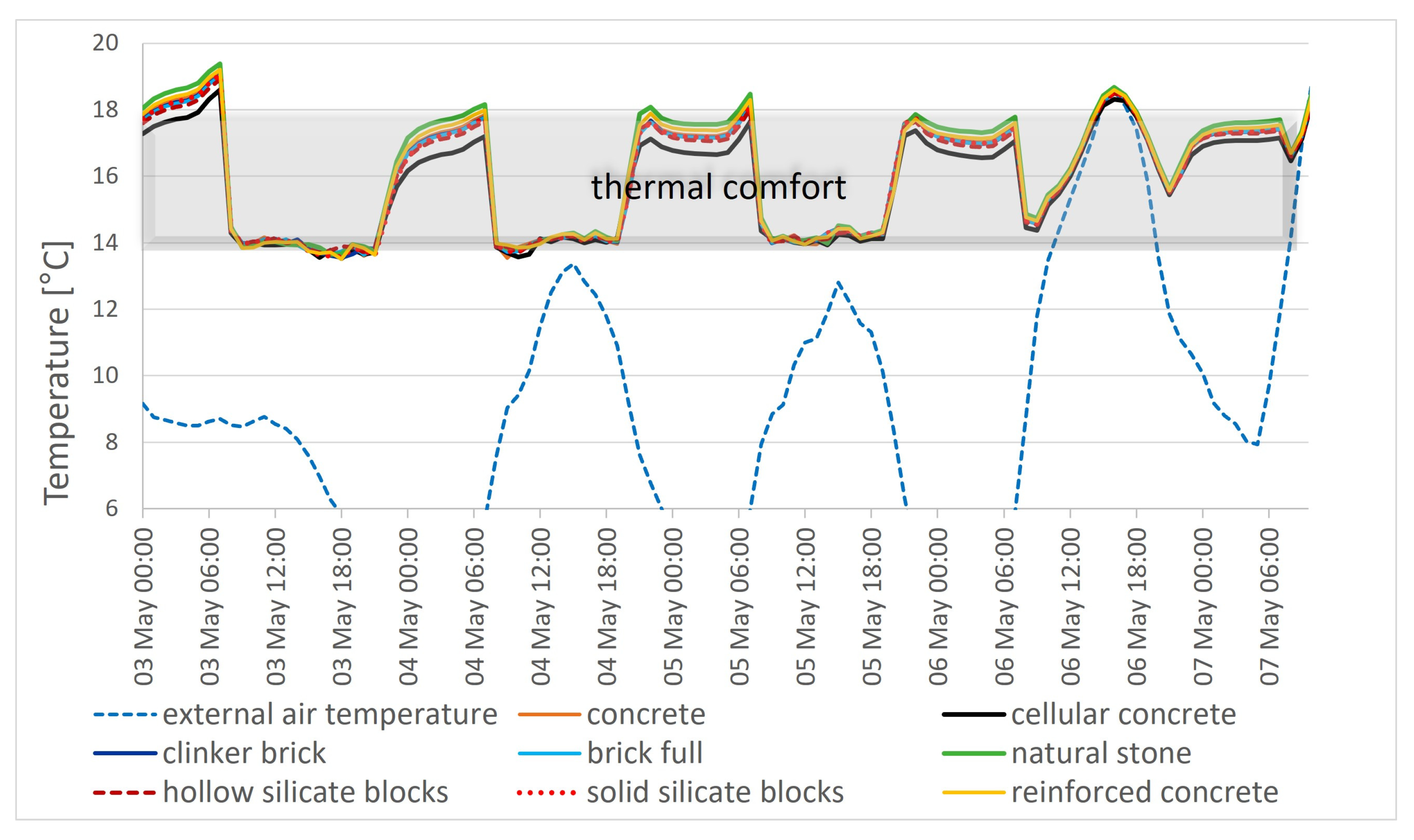
In order to better illustrate the behaviour of the thermal mass, the following section shows the air temperature distributions in the hall during selected short periods of high and low outdoor temperatures (Figure 11 and Figure 12).
During a week of high outside temperatures, the difference between the air temperatures is between 0.1 and 2.0 °K for the individual material variants. The greatest difference occurs on 23 May at 18:00 and is 2.0 °K (between a natural stone wall and an aerated concrete partition). The highest temperature values can be observed for lightweight aerated concrete structures, for which the difference between the air temperature and the upper limit of the thermal comfort range is almost 8 °K. Analysing the hot five-day period, it can be seen that the upper limit of the comfort temperature range of 18 °C assumed for the hall is exceeded (by 1.0 to 7.8 °K) in each material variant.
According to the conclusions of thermal mass studies carried out around the world, lightweight material reacts fastest to changes in outdoor temperature. In the case of high outdoor air temperature values, a partition made of a material with low thermal mass will be the least desirable in terms of protecting the interior from overheating. The average and maximum values for the indoor air temperature over a hot five-day period in Table 8 confirm the slightly more favourable properties of natural stone compared to aerated concrete in terms of protection against overheating.
When considering the period of low external temperatures (Figure 12), it can be seen that the variant with lightweight aerated concrete has the lowest internal air temperature values. On the other hand, the highest temperatures can be observed in the variant with natural stone, i.e., a material with a high heat capacity value and high thermal conductivity. Due to the nature of the object under analysis and the low temperature values of the comfort zone, it can be seen in Figure 12 that the range of temperature changes for the lightweight material overlaps more with the comfort zone. This is related to the different thermal resistance of the wall in the different variants. The materials of the construction layer differ considerably in their thermal conductivity although they have the same thickness. The result is a variation in resistance and associated heat loss through the hall cladding. The period under analysis (May and June) is characterised by large diurnal fluctuations in outdoor temperature. Hence, during the numerous cool days during this period (Table 9), increased thermal losses can reduce indoor comfort. Conversely, during the hot period, the capacity for effective accumulation is not properly utilised, due to the lack of night-time interior cooling.
As a result, despite the markedly different properties of the materials used, very little variation is obtained in the results of the predicted mean evaluation index over a two-month period (Table 10).
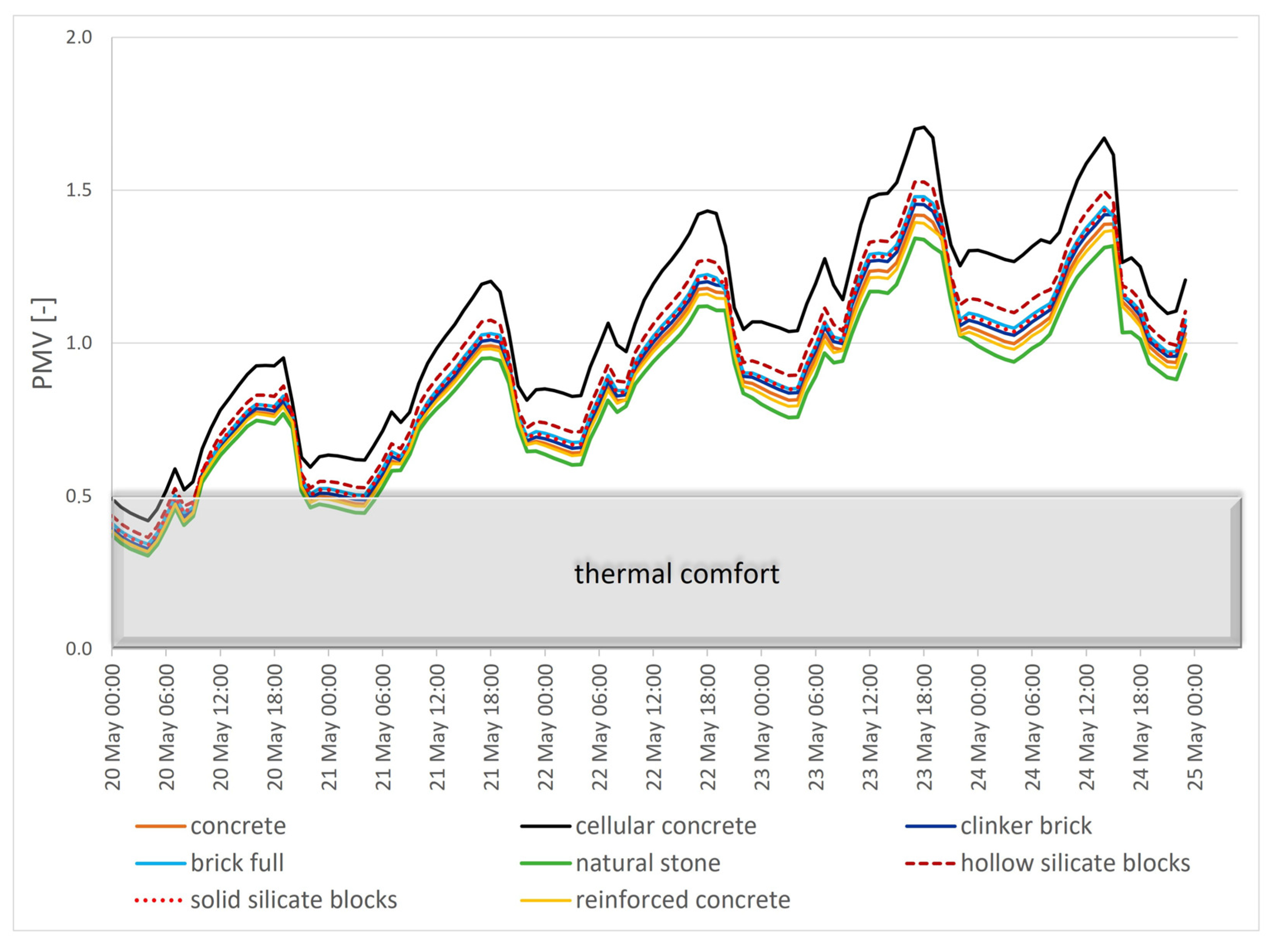
Figure 13 illustrates the distribution of the PMV for the five-day average of high outside temperatures. As in the case of indoor air temperature, the highest PMV values are found in aerated concrete construction and the lowest in natural stone.
The results obtained for the long period (Table 10) are due to the large diurnal temperature fluctuations in the spring and summer months analysed, the specific way in which the building is used and the form of the wall material variants (same thickness of the structural layer).
Analysing the five-day period of high outdoor temperatures, it can be seen that the natural stone variant has the highest number of hours (18 h) during which thermal comfort conditions prevail (Table 11). Materials with a high thermal capacity (natural stone, reinforced concrete, concrete) are characterised by better thermal conditions on hot days compared to others. The worst performer is the variant with lightweight aerated concrete, for which, during 6 h of all 120 h, the PMV value is in the range of −0.5 < PMV < +0.5.
Intensive cooling of the massive interior during the night is one of the best known and at the same time simplest ways to protect buildings from overheating. In the analysed building, no such treatment was found, although it was recommended in the technical design of the building. Therefore, for the exterior wall material variants previously adopted for analysis, the effect of night cooling on thermal comfort was checked using Design Builder. In the simulation analyses, two different methods of night cooling of the building were considered: mechanical or natural ventilation. In the simulation results presented below, there are also references to a variant without night cooling. Although such a way of using the building in summer is not rational, its consideration is based on the actual use of the hall.
In modelling the hall, it was determined that the minimum required fresh air flow per player is 30 m3/h [45]. For 50 people playing, an air exchange of 1.500 m3/h will meet the hygienic needs of the users. The minimum fresh air flow during the day must be provided by mechanical ventilation in a situation where the building has no windows open and no natural ventilation. The maximum capacity of the air handling unit designed for this building corresponds to an air exchange rate of 0.75 ac/h (the maximum ventilation capacity is 9000 m3/h, and the volume of the hall is about 12075 m3). In the case of mechanical ventilation at night (23:00 to 6:00), the intensity of air exchange was assumed at 20% of the maximum value, and then 100%. Night-time natural ventilation was implemented in the simulations in the form of window tilting (40% opening) from 23:00 to 6:00, throughout the analysis period. The actual air exchange with the windows tilted during the night is calculated by the program depending on the current climatic conditions, i.e., outdoor temperature and wind direction and speed.
During the day, the windows can be tilted between 8:00 and 22:00 according to the actual use of the hall and depending on the external conditions (with the condition Tout > Tint—windows closed). The value of the minimum temperature of the indoor air during the tilting of windows during the day and night is 14 °C, its achievement is associated in the simulation algorithm with the closing of windows.
Table 12 summarises the results of calculating the maximum indoor air temperature for all three night-time ventilation scenarios for the building and for all eight exterior wall material variants.
Again, it should be noted that the differences caused by the type of wall material, within the same night ventilation method, are small. When mechanical ventilation was used at night to cool the body of the building, operating at 100% efficiency, the difference in the value of the maximum indoor air temperature between the extreme variants was only 1.2 °K. When natural ventilation, which induces less intensive air exchange than mechanical ventilation, was used at night, the differences between the adopted eight variants were even smaller, amounting to a maximum of 0.7 °K. As before, slightly lower values of maximum indoor air temperature were observed for materials with high thermal capacity (natural stone, reinforced concrete) compared to lightweight materials (aerated concrete). Therefore, it can be concluded that in the case of a building with a large volume, the type of construction material used and the associated thermal capacity of the interior are only of limited importance in shaping thermal comfort in spring and summer.
The air exchange rate during the night was significant for thermal conditions in the building interior throughout the analysis period. With mechanical ventilation operating at the design recommended minimum level (20%), the maximum indoor air temperature for all variants was lower by only 0.4–0.6 °K compared to the variant without night-time ventilation. Mechanical ventilation operating at its maximum capacity guaranteed a reduction in the maximum indoor temperature by 1.2–1.6 °K. If natural ventilation of the building at night had been used, maximum temperatures would have been lower by up to 2.4–3.3 °K with respect to the variant without night-time ventilation.
As before, a five-day period of high outdoor temperatures was selected for detailed analysis. Figure 14 and Figure 15 compare the resulting indoor air temperature values for two extremes in terms of the heat capacity of materials. Opening windows at night results in a reduction in daytime indoor air temperature (e.g., at 14:00) of 2.2–3.3 °K for aerated concrete and 2.0–2.5 °K for natural stone compared to the variant without night-time ventilation. The use of mechanical ventilation at night (0.75 ac/h) on the analysed days of 20–24 May reduced interior temperature values to a lesser extent than natural ventilation. This is due to the higher intensity of natural air exchange compared to the possibility of mechanical ventilation. The stone wall cooled naturally at night, and was characterised by interior air temperature values closer to the comfort zone (Figure 15).
Table 13 summarises the number of hours in the thermal comfort range (the condition 0.5 < PMV < +0.5 is met), for the considered variants of night-time cooling and eight different building materials. Significant differences appear with changes in the intensity of night-time ventilation. When natural night-time ventilation, the most effective in this hall, is used, the number of hours in the thermal comfort range increases by 28.1–32.4% compared to the option without night-time cooling. The use of mechanical ventilation, operating at night at maximum capacity, increased the number of hours in the thermal comfort range by 14.1–21.3%. It should also be noted that the use of maximum-capacity mechanical ventilation involves additional costs, associated with significant energy consumption.
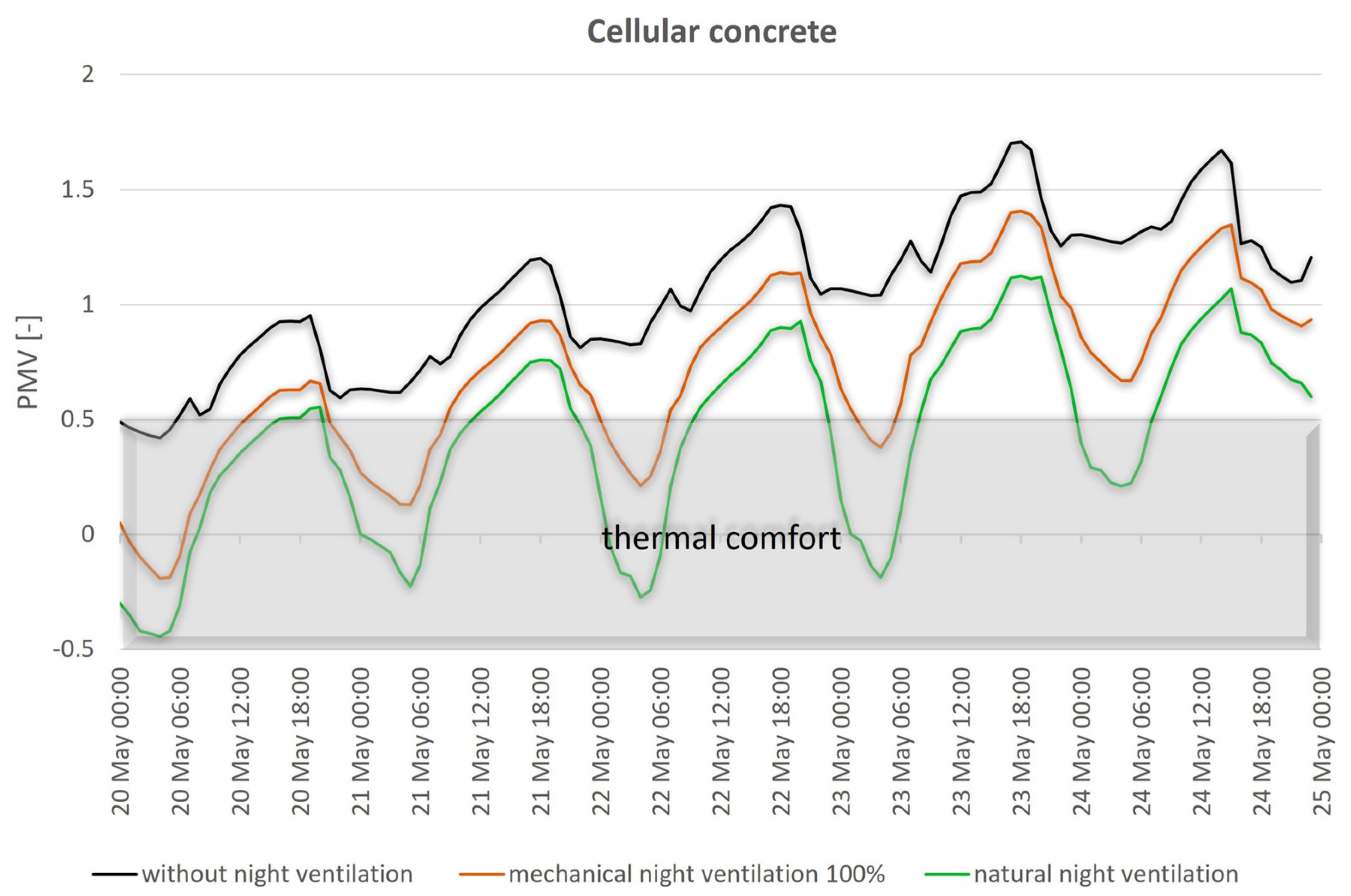
To graphically illustrate the effect of night-time cooling on thermal comfort, Figure 16 and Figure 17 show the distribution of predicted average rating index values for selected construction materials—aerated concrete and natural stone. As before, a five-day period with the highest outdoor temperatures was selected from the two-month interval analysed. The PMV values, for neither of the analysed options, coincide completely with the thermal comfort zone. However, the graph that takes into account natural night-time ventilation runs closest to this zone, in both cases. In the case of structural walls made of stone and natural cooling, at night for most hours, the PMV value ranges from −0.5 to +0.8, which, according to the Fanger scale, means comfortable or indifferent conditions for hall users (Figure 17). The use of lightweight aerated concrete in the structural layer causes the distribution of PMV values to fall within a wider range of −0.4 to +1.1, despite the natural ventilation with cool air at night (Figure 16). The black graph (the variant without night-time cooling) has little overlap with the thermal comfort zone in both cases of the materials used. This means that those using the facility will be clearly too warm during this time. The use of mechanical ventilation for night-time cooling (orange graph) lowered PMV values, but due to its limited rate, it was not as effective as natural ventilation.
To complete the information on the sports arena of the University of Agriculture, it is necessary to mention the modification of the ventilation system, which the authors learned about after the measurements were taken. In view of the building’s repeated overheating in summer and the great discomfort felt by users, a mechanical cooling system was installed in the arena. The decision to upgrade confirmed the problem of the lack of thermal comfort during high outdoor temperatures noted during the survey (2013 and 2014).

4. Discussion

In passive buildings, protection against overheating is crucial and should be an essential step in the design process. The choice of specific solutions must be well thought out and preceded by a thorough analysis of both the efficiency of a given system, as well as its energy consumption and implementation costs. Trying to minimise total energy consumption and maintain thermal comfort conditions without mechanical cooling is very difficult to achieve. In the design and construction documentation of the analysed sports hall, air conditioning was not provided. Among the available passive tools, the authors looked for effective methods to reduce overheating.
Sports facilities are spaces with specific microclimatic requirements due to the required operating temperature and physical activity of users. Ensuring thermal comfort is particularly important there, as it can affect the performance and health of athletes. Most sports facilities are multi-purpose arenas, where several activities with different metabolic rates are performed. Determining a comfortable thermal environment for all athletes and spectators is difficult and can lead to an overestimation of thermal sensation in some athletes. This article examines conditions for lower-activity athletes.
In the context of overheating and reducing thermal discomfort on hot days, materials with a high effusivity factor are more desirable. However, in the case of well-insulated low-energy buildings with a very large volume and a small number of partitions (such as the UA sports hall), their thermal capacity is not the main factor that affects thermal comfort in summer. Night-time ventilation is key to preventing overheating. It is known that the thermal component of the natural air exchange mechanism functions most effectively on cooler days and nights. The difference in indoor and outdoor air temperature creates a difference in density and pressure, which in turn translates into air circulation through natural convection. The pressure difference, and thus the ventilation rate, is proportional to the temperature difference between the indoor and outdoor air. Given the thermal capacity, the effects of material variation are greater the more intensive the night-time ventilation of the interior and the associated nightly cooling effect of the interior. The analysis shows that the effects of night-time mechanical ventilation of a large-volume hall are weaker compared to natural night-time ventilation. This is due to the relatively low power of mechanical ventilation relative to the total volume of the interior. The intensity of mechanical ventilation was related to the expected number of users, not the interior volume. The maximum capacity of mechanical ventilation corresponds to a volumetric air exchange of 0.75 h−1. Night-time natural ventilation is more effective in discharging thermal mass due to an average number of air exchanges of about 4 h−1. Analyses of the effect of night-time cooling on thermal conditions in passive buildings have also been the subject of separately published articles [46,47].
The unfavourable orientation of the analysed building, as well as the effectively insulated shell, caused a significant increase in internal temperature during the study period. Night-time ventilation is used sporadically in the hall building due to various practical considerations: automatic closing of windows in windy or rainy conditions and fear of burglary. Without close cooperation between designers and users on how to discharge excess stored energy in summer, advanced passive buildings will not be able to protect consumers from discomfort.
It is worth mentioning that the adaptive comfort model is increasingly often used to assess thermal conditions in buildings with hybrid ventilation. In the model, during a long period of rising outdoor air temperature, the human body adapts slowly to these conditions and the range of comfortable conditions shifts towards higher temperatures. This type of approach can only be used if a building’s occupants are able to adjust their clothing or open the windows in response to changing environmental conditions. By accounting for occupant adaptation, a more lenient assessment of the microclimate makes it possible, once relevant requirements have been met, to accept conditions treated as overheating under Fanger’s criterion. Although the adaptive method of determining thermal comfort has its limitations, it should be used wherever possible. The synergy of an indoor environment controlled by the occupants in response to the prevailing outdoor conditions and the low energy consumption of passive buildings is becoming an indispensable part of sustainability. By factoring in the thermoregulatory capabilities of the body and using the basic principles of heat exchange with the environment, it is possible to ensure occupant comfort with minimal operating costs.

5. Conclusions

Based on the analysis of the impact of material solutions and night-time ventilation on thermal comfort in a passive sports hall, the following conclusions can be made:
  • Night-time cooling can have a large impact on protection against overheating in passive buildings during summer. Intensive natural ventilation is associated with the highest number of hours in the comfort range: 28.1–32.4% more hours compared to the variant without night-time ventilation. The use of mechanical ventilation, operating at night at maximum capacity, will result in an increase in the number of hours with air temperatures in the −0.5 < PMV < +0.5 range by only 14.1–21.3%.
  • In the case where natural ventilation was used at night the maximum indoor air temperature during the day was lower by 2.4–3.3 °K, relative to the case where no night-time ventilation was used.
  • With mechanical ventilation operating during the night at its design-recommended minimum level (20%), the maximum internal air temperature is only 0.4–0.6 K lower than without night ventilation. Mechanical ventilation operating at its maximum capacity can reduce maximum indoor temperature by 1.2–1.6 K.
  • In the hall under study, the design of the ventilation system addressed the necessary hygienic air exchange resulting from the maximum number of users (maximum 0.75 ach). The design of the facility, taking into account thermal comfort, should allow much more intensive forced air exchange, even several exchanges during the hour [46].
  • One important advantage of mechanical ventilation is its independence from external conditions, certainty of operation and adjustability. However, its significant cost and additional energy consumption is a downside.
  • Natural ventilation depends directly on climatic conditions, poses problems of safety, protection from flooding, wind damage to windows, etc.
  • In the case of a well-insulated sports hall with a very large volume, the thermal capacity of exterior wall materials has little effect on improving thermal conditions. It is not significant in shaping thermal comfort in summer. This is due to the low volume of wall materials in relation to the much greater volume of this building. In the case of residential or office buildings with small rooms, these proportions are different and the influence of the volume of the partitions can be much greater.
  • Solid materials (natural stone, reinforced concrete), with high values of effusivity coefficient and temperature equalisation, allow slightly better results than lightweight materials with lower thermal conductivity.
  • The high thermal capacity of the envelope reduces the occurrence of very high air temperature values inside the building, thus reducing overheating.
  • The type of partition material is all the more important the greater the night-time air exchange rate.
  • Opening windows at night results in a reduction in the daytime indoor air temperature (e.g., at 2 p.m.) by 2.2–3.3 K for lightweight cellular concrete and 2.0–2.5 K for natural stone compared to the alternative without night-time ventilation.
  • The use of high thermal capacity materials in partitions usually promotes a reduction in project costs and provides better structural capabilities (carrying higher loads).
Thermal comfort is a broad, multi-criteria issue that is difficult to analyse comprehensively. The authors are aware of the many limitations associated with the measurements presented. This study was an effort to simplify the assessment of microclimatic conditions in highly specific buildings like sports halls. When undertaking the study, the authors were under no illusion that they would be able to accurately determine the effect of point, directed solar radiation for every location and every moment. In addition, the building’s users did not have strictly assigned locations and visit times. Even in the case of a relatively stationary volleyball game, they were still moving around the hall. In addition, measurements were only made for certain specific metabolic and clothing insulation data. The sports hall can be the site of many different activities as a part of different sports disciplines. The authors focused on activities customarily carried out during the academic year with students and performed the analysis only for this specific-yet-broad user group. All of this makes the information on thermal comfort and that derived from measurements and from simulations indicative and should be treated as an average in terms of place and time.
The location of the device may also have had some small impact on the final results. However, it was the only possibility to perform measurements during the building’s routine operation. The location of the instrument was dictated by concern for its safety, as well as technical possibilities, based on the hall’s form of use. The sensors’ location could not interfere with the sports activities schedule.
It should be added that there are no clear, established guidelines on measuring thermal comfort in sports facilities in recognised standards and in the literature. In addition, there is a lack of consistency and clearly defined categories of sports, metabolic values and the corresponding thermal comfort temperature. It is therefore difficult to formulate general conclusions for this group of buildings, especially when they are built to be passive buildings, and for a specifically defined user group.
The authors are aware of the unavoidable approximations and simplifications that result from the manner, conditions and timing of measurements in the hall. Similar limitations also apply to simulation results concerning the average conditions in the hall’s centre. Nevertheless, the results obtained in this way should, in the authors’ opinion, allow meaningful comparisons of the analysed alternatives and aid in the search for correct directions for the design of such facilities.

Author Contributions

Conceptualization, A.D. and T.K.; Methodology, A.D. and T.K.; Formal analysis, A.D., T.K. and E.P.; Resources, A.D., T.K. and E.P.; Data curation, A.D. and T.K.; Writing—original draft, A.D., T.K. and E.P.; Writing—review & editing, A.D., T.K. and E.P.; Project administration, E.P. All authors have read and agreed to the published version of the manuscript.

Funding

This research received no external funding.

Data Availability Statement

Data are contained within the article.

Conflicts of Interest

The authors declare no conflict of interest.

Abbreviations

Nomenclature
athermal diffusivity coefficient (temperature compensation coefficient)
cpspecific heat capacity [J/(kg × K)]
e effusivity   of   the   material   [ W × s 1 2 m 2 × K ]
PMVPredicted Mean Vote
PPDPredicted Percentage of Dissatisfied
Tintindoor air temperature [°C]
Toutoutdoor air temperature [°C]
Uheat transfer coefficient W/m2K
Greek letters
λthermal conductivity coefficient [W/mK]
ρdensity [kg/m3]

References

  1. Kuczyński, T.; Staszczuk, A. Experimental study of the influence of thermal mass on thermal comfort and cooling energy demand in residential buildings. Energy 2020, 195, 116984. [Google Scholar] [CrossRef]
  2. Perino, M.; Serra, V. Switching from static to adaptable and dynamic building envelopes: A paradigm shift for the energy efficiency in buildings. J. Façade Des. Eng. 2015, 3, 143–163. [Google Scholar] [CrossRef]
  3. Stazi, F.; Bonfigli, C.; Tomassoni, E.; Di Perna, C.; Munafò, P. The effect of high thermal insulation on high thermal mass: Is the dynamic behaviour of traditional envelopes in Mediterranean climates still possible? Energy Build. 2015, 88, 367–383. [Google Scholar] [CrossRef]
  4. Givoni, B. Passive cooling of buildings by natural energies. Energy Build. 1979, 2, 279–285. [Google Scholar] [CrossRef]
  5. Holmes, M.; Hacker, J. Climate change, thermal comfort and energy: Meeting the design challenges of the 21st century. Energy Build. 2007, 39, 802–814. [Google Scholar] [CrossRef]
  6. Slee, B.; Parkinson, T.; Hyde, R. Quantifying useful thermal mass: How much thermal mass do you need? Archit. Sci. Rev. 2014, 57, 271–285. [Google Scholar] [CrossRef]
  7. Reynders, G.; Nuytten, T.; Saelens, D. Potential of structural thermal mass for demand-side management in dwellings. Build. Environ. 2013, 64, 187–199. [Google Scholar] [CrossRef]
  8. Dominkoviĉ, D.F.; Wahlroos, M.; Syri, S.; Schrøder Pedersen, A. Influence of different technologies on dynamic pricing in district heating systems: Comparative case studies. Energy 2018, 153, 136–148. [Google Scholar] [CrossRef]
  9. Gryś, S. Określanie czasu termicznego wymuszenia skokowego w celu wykrycia zmiany grubości pierwszej warstwy struktury dwuwarstwowej. In Proceedings of the XLVI Intercollegiated Conference of Metrologists MKM’2014 and 19th International Metrolog Seminar MSM’2014, Gdańsk, Poland, 13–16 September 2014. [Google Scholar]
  10. Minkina, W. Pomiary Termowizyjne—Przyrządy i Metody; Wydawnictwo Politechniki Częstochowskiej: Częstochowa, Poland, 2004; ISBN 83-7193-237-5. [Google Scholar]
  11. Dokka, T.H. Varmelagringseffekt Ved Bruk av Tunge Materialer i Bygninger (Effect of Thermal Storage by Use of Heavy Materials in Buildings); SINTEF Report STF 50 A05045; SINTEF: Trondheim, Norway, 2005; ISBN 8214035694. [Google Scholar]
  12. Gorgolewski, M. Framing Systems and Thermal Mass. Mod. Steel Constr. 2007, 47, 45. [Google Scholar]
  13. Hietamakai, J.; Kuoppala, M.; Kalema, T.; Taivalantti, K. Thermal Mass of Buildings—Central Researches and their Results; Report 2003:174; Tampere University of Technology, Institute of Energy and Process Engineering: Tampere, Finland, 2003. [Google Scholar]
  14. Johannenson, G. Possibility to Energy Efficient Houses by New Integrated Calculation Approach; ByggTeknik, No. 3: Stockholm, Sweden, 2006. [Google Scholar]
  15. Pilch, Z. Beton w Budynkach Efektywnych Energetycznie, Korzyści z Masy Termicznej; Stowarzyszenie Producentów Cementu: Kraków, Poland, 2007. [Google Scholar]
  16. Tasnuva, A. Investigating the Impact of Thermal Mass towards Energy Efficient Housing in Canada. Master’s Thesis, Rajshahi University of Engineering and Technology, Rajshahi, Bangladesh, 2007. [Google Scholar]
  17. Yinping, Z.; Kunping, L.; Qunli, Z.; Hongfa, D. Ideal thermophysical properties for free-cooling (or heating) buildings with constant thermal physical property material. Energy Build. 2006, 38, 1164–1170. [Google Scholar]
  18. Givoni, B. Effectiveness of mass and night ventilation in lowering the indoor daytime temperatures, Part I: 1993 experimental periods. Energy Build. 1998, 28, 25–32. [Google Scholar] [CrossRef]
  19. Thomas, J.M.; Algohary, S.; Hammad, F.; Soboyejo, W.O. Materials selection for thermal comfort in passive solar buildings. J. Mater. Sci. 2006, 41, 6897–6907. [Google Scholar] [CrossRef]
  20. Roberz, F.; Loonen, R.C.G.M.; Hoes, P.; Hensen, J.L.M. Ultra-lightweight concrete: Energy and comfort performance evaluation in relation to buildings with low and high thermal mass. Energy Build. 2017, 138, 432–442. [Google Scholar] [CrossRef]
  21. Guglielmini, G.; Magrini, U.; Nannei, E. The influence of the thermal inertia of building structures on comfort and energy consumption. J. Build. Phys. 1981, 5, 59–72. [Google Scholar] [CrossRef]
  22. Rehman, A.; Shuli Liu, M.; Shukla, A. A state of art review on the district heating systems. Renew. Sustain. Energy Rev. 2018, 96, 420–439. [Google Scholar]
  23. Romanchenko, D.; Kensby, J.; Odenberger, M.; Johnsson, F. Thermal energy storage in district heating: Centralised storage vs. storage in thermal inertia of buildings. Energy Convers. Manag. 2018, 162, 26–38. [Google Scholar] [CrossRef]
  24. Masy, G.; Georges, E.; Verhelst, C.; Lemort, V.; Andrĕ, P. Smart grid energy flexible buildings through the use of heat pumps and building thermal mass as energy storage in the Belgian context. Sci. Technol. Built Environ. 2015, 21, 800–811. [Google Scholar] [CrossRef]
  25. Gregory, K.; Moghtaderi, B.; Sugo, H.; Page, A. Effect of thermal mass on the thermal performance of various Australian residential constructions systems. Energy Build. 2008, 40, 459–465. [Google Scholar] [CrossRef]
  26. Berge, B. The Ecology of Building Materials; Oxford Architectural Press: Oxford, UK, 2001. [Google Scholar]
  27. Loonen, R.C.G.M.; Trčka, M.; Cóstola, D.; Hensen, J.L. Climate adaptive building shells: State-of-the-art and future challenges. Renew. Sustain. Energy Rev. 2013, 25, 483–493. [Google Scholar] [CrossRef]
  28. Belka, W. Concrete as Thermal Mass in Low Energy Buildings; Warsaw University of Technology: Warsaw, Poland, 2016. (In Polish) [Google Scholar]
  29. Golański, M. Building materials as thermal mass in Buildings. Przegląd Bud. 2011, 12, 88–93. (In Polish) [Google Scholar]
  30. Dudzińska, A. Ways of Shaping and Exploitation of Passive Public Utility Buildings Taking into Consideration the Requirements for Thermal Comfort. Ph.D. Thesis, Cracow University of Technology, Krakow, Poland, 2019. [Google Scholar]
  31. Architektura pasywna Pyszczek i Stelmach Sp., J. Hala Sportowa Uniwersytetu Rolniczego w Krakowie. Available online: http://architekturapasywna.pl/portfolio/centered-stack-2-2-2-4-2/ (accessed on 24 April 2023).
  32. Kisilewicz, T.; Dudzińska, A. Summer overheating of a passive sports hall building. Arch. Civ. Mech. Eng. 2015, 15, 1193–1201. [Google Scholar] [CrossRef]
  33. Dudzińska, A.; Kotowicz, A. Features of materials versus thermal comfort in a passive building. Procedia Eng. 2015, 108, 108–115. [Google Scholar] [CrossRef]
  34. PN-EN ISO 7730:2006; Ergonomics of the Thermal Environment—Analytical Determination and Interpretation of Thermal Comfort using Calculation of the PMV and PPD Indices and Local Thermal Comfort Criteria. ISO: Geneva, Switzerland, 2006.
  35. PN-EN ISO 7726: 2001; Ergonomics of the Thermal Environment—Instruments for Measuring Physical Quantities. ISO: Geneva, Switzerland, 2001.
  36. Fanger, P.O. Thermal Comfort; Arkady: Warsaw, Poland, 1974. [Google Scholar]
  37. PN-EN 16798-1:2019-06; Indoor Environmental Input Parameters for Design and Assessment of Energy Performance of Buildings Addressing Indoor Air Quality, Thermal Environment, Lighting and Acoustics. European Committee for Standardization: Brussels, Belgium, 2019.
  38. PN-EN 12464-1:2012; Światło i Oświetlenie. Oświetlenie Miejsc Pracy, Część 1: Miejsca Pracy we Wnętrzach. PKN: Warsaw, Poland, 2012.
  39. PN-EN ISO 9972:2015-10; Cieplne Właściwości Użytkowe Budynków—Określanie Przepuszczalności Powietrznej Budynków—Metoda Pomiaru Ciśnieniowego z Użyciem Wentylatora. PKN: Warsaw, Poland, 2009.
  40. Jóźwiak, J.; Podgórski, J. Statystyka od Podstaw; PWE: Warsaw, Poland, 2009. [Google Scholar]
  41. Matysiak-Rakoczy, K. Budowa Domu z Silikatów—Bloczki Silikatowe, Cegły, Płytki. Available online: https://muratordom.pl/budowa/sciany-murowane/budowa-domu-z-silikatow-bloczki-silikatowe-aa-6Pfy-PK5J-Sg7E.html (accessed on 15 April 2023).
  42. EN ISO 10456; Materiały i Wyroby Budowlane—Tabele Wartości Projektowych, Określanie Deklarowanych i Projektowych Wartości Cieplnych. ISO: Geneva, Switzerland, 2009.
  43. EN ISO 6946:2017; Komponenty Budowlane i Elementy Budynku—Opór Cieplny i Współczynnik Przenikania Ciepła—Metody Obliczania. ISO: Geneva, Switzerland, 2017.
  44. PN-83/B-03430; Wentylacja w Budynkach Mieszkalnych Zamieszkania Zbiorowego i Użyteczności Publicznej—Wymagania (Uaktualniona 8 Lutego 2000 Roku PN-83/B-03430/Az3:2000). PKN: Warsaw, Poland, 2000.
  45. Dudzińska, A.; Kisilewicz, T. Alternative Ways of Cooling a Passive School Building in Order to Maintain Thermal Comfort in Summer. Energies 2020, 14, 70. [Google Scholar] [CrossRef]
  46. Dudzińska, A.; Kisilewicz, T. Efficiency of night ventilation in limiting the overheating of passive sports hall, MATBUD’2020–Scientific-Technical Conference: E-mobility. Sustain. Mater. Technol. 2020, 322, 01031. [Google Scholar] [CrossRef]
  47. Artmann, N.; Manz, H.; Heiselberg, P. Parameter study on performance of building cooling by night-time ventilation. Renew. Energy 2008, 33, 2589–2598. [Google Scholar] [CrossRef]
Figure 1. South elevation of the hall (author’s archive).
Energies 16 07698 g001
Figure 2. Southeast elevation (ELEWACJA E) and northwest elevation of the sports hall (ELEWACJA W) [32].
Energies 16 07698 g002
Figure 3. Babuc A digital microclimate meter (author’s archive).
Energies 16 07698 g003
Figure 4. Parameters used in the predicted mean vote (PMV) calculation and relation to thermal sensation scale.
Energies 16 07698 g004
Figure 5. The south-east (left) and north-west (right) elevations of the University of Agriculture hall generated in Design Builder.
Energies 16 07698 g005
Figure 6. Indoor air temperature distribution during the summer measurement and the values obtained from the simulation model for the studied sports arena.
Energies 16 07698 g006
Figure 7. Microclimate measurement meter (in red circle) shielded by a goal net during the hall survey in May (author’s archive).
Energies 16 07698 g007
Figure 8. (a) Distribution of indoor air temperature. (b) PMV indicator in the first measurement cycle.
Energies 16 07698 g008
Figure 9. (a) Distribution of indoor air temperature. (b) PMV indicator in the 2nd measurement cycle.
Energies 16 07698 g009aEnergies 16 07698 g009b
Figure 10. Comparison of the conductivity and heat capacity of the construction materials adopted for analysis.
Energies 16 07698 g010
Figure 11. Distribution of indoor air temperature for selected days of high outdoor temperatures.
Energies 16 07698 g011
Figure 12. Distribution of indoor air temperature for a selected five-day period of low outdoor temperatures.
Energies 16 07698 g012
Figure 13. Distribution of the index of the predicted mean score for the selected hot five-day period.
Energies 16 07698 g013
Figure 14. Indoor air temperature distribution for the aerated concrete variant, during a selected five-day period of high outdoor temperatures.
Energies 16 07698 g014
Figure 15. Indoor air temperature distribution for the natural stone variant, during a selected five-day period of high outdoor temperatures.
Energies 16 07698 g015
Figure 16. Distribution of PMV values for the selected five-day period for the variant of structural walls made of aerated concrete.
Energies 16 07698 g016
Figure 17. Distribution of PMV for the selected five-day period for the variant of natural stone structural walls.
Energies 16 07698 g017
Table 1. Load on the University of Agriculture sports hall during the second measurement round (adopted for model validation).
DateHoursNumber of Occupied SectorsApproximate Number of
People in the Room/h
20 May11.00–14.00250
14.00–16.30125
17.30–22.00215
21 May8.00–10.00250
10.00–11.00125
11.00–15.30250
15.30–17.0000
17.00–18.00125
18.00–19.00250
19.00–20.00110
22 May8.30–10.00125
10.00–11.00230
11.30–13.00375
13.00–14.30125
14.30–16.0000
16.00–18.00230
18.00–20.00250
20.00–22.00115
23 May8.00–11.00125
11.00–12.00230
12.00–16.0000
16.00–19.00350
19.00–20.00110
20.00–22.00375
24 May9.00–15.00350
Table 2. Window opening times assumed in the modelling on the southeast and northwest sides of the University of Agriculture hall.
Date of
Measurement
Windows on the Southeast FacadeWindows on the
Northwest Facade
20 Maytilted 7.00–21.00tilted 8.00–21.00
21 Mayclosedclosed
22 Maytilted 14.00–20.00tilted 19.00–20.00
23 Maytilted 8.00–12.00 and 16.00–21.00tilted 19.00–22.00
24 Maytilted 8.00–20.00tilted 9.00–18.00
Table 3. Average measured values of indoor environmental parameters in the UR hall.
Environmental Parameters
(Average Values)
UnitFirst Measurement SeriesSecond Measurement Series
Indoor air temperature ta[°C]27.924.1
Indoor air humidity[%]58.2850.85
Radiation temperature tr[°C]28.824.30
PMV[-]1.142.26
PPD[%]33.1584.18
Table 4. Results of the May 2014 survey on environmental conditions in the University of Agriculture sports hall.
Fanger ScaleHow Would You Rate the Temperature in the Hall?
WomanMan
+3 (hot)30-
+2 (warm)353
+1 (quite warm)191
0 (neutral)115
−1 (quite cool)--
−2 (cool)--
−3 (cold)--
Table 5. Characteristics of the construction materials adopted for the analysis according to [20,42,43,44].
Construction MaterialDensity ρ [kg/m3]Thermal Conductivity λ [W/(m × K)]Specific Heat c
[J/(kg × K)]
Thermal Capacity C
[MJ/m3 × K]
Thermal
Diffusivity
(Temperature Compensation Coefficient) a
[m2/s]
Material Effusivity e
[(W × s1/2)/(m2 × K)]
Concrete22001.38401.857.03 × 10−71549.97
Aerated concrete6000.218400.504.17 × 10−7325.33
Clinker brick masonry19001.058801.676.28 × 10−71324.99
Solid brick masonry18000.778801.584.86 × 10−71104.39
Natural stone28003.59202.581.36 × 10−63002.67
Hollow-core silicate masonry units15000.468801.323.48 × 10−7779.23
Silicate masonry units19000.98801.675.38 × 10−71226.70
Reinforced concrete25001.78402.108.10 × 10−71889.44
Table 6. The use of the University of Agriculture sports hall adopted for the simulation.
Day of the WeekHoursNumber of People in the Hall/h
Monday–Friday8:00 to 16:0050
16:00 to 22:0025
Saturday–Sunday9:00 to 20:0050
Table 7. Mean and maximum values of indoor air temperature and radiation temperature for the two-month analysis period and the eight simulation variants adopted.
Construction MaterialIndoor Air Temperature ta [°C]Radiant Temperature tr [°C]
AverageMaximumAverageMaximum
Concrete19.826.020.825.7
Aerated concrete20.027.221.027.0
Clinker brick masonry19.826.120.825.8
Solid brick masonry19.926.320.826.0
Natural stone19.825.620.825.3
Hollow-core silicate masonry units19.926.520.926.2
Silicate masonry units19.926.220.825.9
Reinforced concrete19.825.920.825.6
Table 8. Mean and maximum values of indoor air temperature for the five-day period of high outdoor temperatures (20–24 May).
Construction MaterialIndoor Air Temperature ta [°C]
AverageMaximum
Concrete22.125.0
Aerated concrete23.025.9
Clinker brick masonry22.225.1
Solid brick masonry22.325.2
Natural stone21.924.6
Hollow-core silicate masonry units22.525.4
Silicate masonry units22.325.2
Concrete22.124.9
Table 9. Number of hours for different outside air temperature ranges for the entire analysis period.
Number of Hours with Outdoor Air Temperature < 10 °CNumber of Hours with Outdoor Air Temperature within 10–15 °CNumber of Hours with Outdoor Air Temperature within 15–20 °CNumber of Hours with Outdoor Air Temperature within 20–25 °CNumber of Hours with Outdoor Air Temperature > 25 °C
22648445023965
Table 10. Hourly distribution of PMV for the adopted simulation variants and the two-month calculation period.
Construction MaterialNumber of Hours with −0.5 < PMV< +0.5Number of Hours with PMV > 0.5
Concrete684780
Aerated concrete669782
Clinker brick masonry681783
Solid brick masonry673791
Natural stone678786
Hollow-core silicate masonry units676788
Silicate masonry units675789
Concrete675789
Table 11. Hourly distribution of PMV for the adopted simulation variants and the five-day (20–24 May) calculation period.
Construction MaterialNumber of Hours with −0.5 < PMV < +0.5Number of Hours with PMV > 0.5
Concrete17103
Aerated concrete6114
Clinker brick masonry14106
Solid brick masonry9111
Natural stone18102
Hollow-core silicate masonry units9111
Silicate masonry units11109
Concrete17103
Table 12. Maximum indoor air temperature values for the two-month analysis period without night ventilation and with night cooling applied.
Construction MaterialMaximum Indoor Air Temperature [°C]
No Night-Time CoolingWith 20% Night-Time CoolingWith 100% Night-Time CoolingNatural Night-Time Cross-Ventilation
Concrete26.025.524.623.4
Aerated concrete27.226.825.623.9
Clinker brick masonry26.125.724.723.4
Solid brick masonry26.325.824.723.5
Natural stone25.625.224.423.2
Hollow-core silicatemasonry units26.526.024.923.6
Silicate masonry units26.225.724.723.4
Concrete25.925.424.623.3
Table 13. Number of hours with conditions in the thermal comfort range −0.5 < PMV < +0.5 for the analysed variants without night ventilation and with night cooling applied.
Construction MaterialNumber of Hours with Conditions within the Thermal Comfort Range−0.5 < PMV < +0.5
No Night-Time CoolingWith 20% Night-Time CoolingWith 100% Night-Time CoolingNatural Night-Time Cross-Ventilation
Concrete684742842975
Aerated concrete669712779930
Clinker brick masonry681740835980
Solid brick masonry673733825966
Natural stone678740862992
Hollow-core silicate masonry units676728811952
Silicate masonry units675734828982
Concrete675741847998
Disclaimer/Publisher’s Note: The statements, opinions and data contained in all publications are solely those of the individual author(s) and contributor(s) and not of MDPI and/or the editor(s). MDPI and/or the editor(s) disclaim responsibility for any injury to people or property resulting from any ideas, methods, instructions or products referred to in the content.