Abstract
The uneven load of the electric drive of sucker-rod pumping units causes an increase in the consumption of reactive power, which requires compensation. This article discusses the issue of calculating the processes in sucker-rod pumping units in the case of individual compensation of the reactive power. Mathematical models for calculating the process of changing the capacity of cosine capacitors for reactive power compensation in the starting and steady-state modes of the electric drive of the sucker-rod pumping unit, which are characterized by the periodically varying load and moment of inertia, have been developed. The calculation is based on a mathematical model of the induction motor that takes into account the saturation of the magnetic path and the skin effect in the bars of the deep-bar rotor. The created mathematical model can be used to regulate the capacitance of the capacitors connected to the induction motor in order to reduce the reactive power consumption.
1. Introduction
In global practice, oil extraction in oil fields is carried out mainly with the help of sucker-rod pumps [1,2]. The main elements of the sucker-rod pumping unit (SRPU) are a pump, a string of pipes and rods, a pump jack, an electric motor and starting and control equipment (Figure 1).
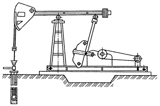
Figure 1.
Sucker-rod pumping unit.
The plunger of the sucker-rod pump is driven by a pump jack with the help of a string of rods, which converts the rotary motion of the electric motor into a reciprocating motion. During the downward movement of the plunger, the static load at the point of suspension of the rods acts in the same direction. If there are no counterweights, the torque applied to the motor shaft from the side of the pump jack has a negative value, which makes the motor switch to a generator mode. To avoid this, pump jacks are designed to provide an option of balancing the weight of the rods with special counterweights, as shown in the scheme (Figure 2).
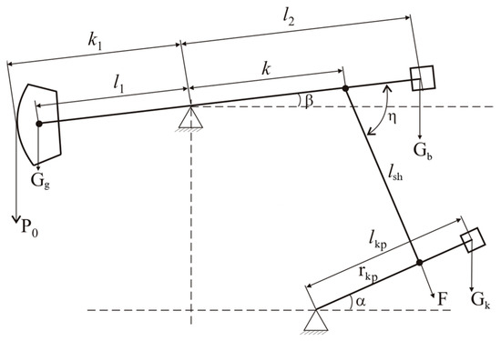
Figure 2.
Kinematic diagram of the pump jack and location of the counterweights: k1 = 2.5 m, k = 2.5 m, lsh = 3.0 m, rkp = 1.0 m, Gk = 27.93 kN, Gg = 3.82 kN.
For driving SRPU pump jacks, three-phase, squirrel-cage induction motors (IM), deep-bar or double-cage, which have an increased starting torque, are most commonly used [2].
The SRPU electric drive has a number of specific features:
- (a)
- A periodically varying load, which is characterised by alternating maximum and minimum values (Figure 3);
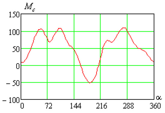 Figure 3. The load torque Mc vs. the angle α of rotation of the crankshaft of the pump jack.
 - (b)
- A periodically varying moment of inertia, the maximum value of which significantly exceeds the moment of inertia of the motor;
- (c)
- The stochastic nature of the load at the starting moment, which is determined by the position of the crank shaft of the pump jack.
Contemporary technologies have significantly increased the requirements for the methods and means of analysis of SRPU electric drives. In particular, the level of automation is increasing in the direction of the development of intelligent control stations, not only for individual wells but also for entire oil fields [3,4,5,6]. Since experimental studies are too expensive, the main attention of researchers is focused on mathematical modelling. Modelling makes it possible to study the behaviour of a system in various emergencies, which are difficult to implement in laboratory installations and even more so in operating industrial units. In addition, automated control systems are based on mathematical models, the adequacy and speed of which determine the efficiency and reliability of the operation of oil production facilities.
In the literature, a large number of works [7,8,9,10,11,12] tackle the problem of mathematical modelling of SRPU operation, in which problematic issues of the functioning of the electrical equipment, mechanical part, pipelines, chemical properties of oil, etc., are considered.
Extraction of oil from wells using pump jacks is very energy-consuming. The cost of electricity can reach 50% of the oil production cost [13], which is why the problem of energy saving is of topical importance. Therefore, due attention should be paid to the issue of the rational selection of SRPU elements and the optimal management of their operation.
The main consumer of electric power in the SRPU is an IM. Despite the quite simple design of induction motors, from the point of view of the theory of automatic control, they are complex, non-linear, multi-dimensional objects with various forms of mathematical description, which results in a large number of their mathematical models [14,15,16]. Therefore, when conducting research on asynchronous electric drives by means of mathematical modelling, it is important to choose a model every time that will satisfy the requirements for the accuracy of the results, the amount of computer memory and the speed of obtaining the results.
The depths of oil wells vary and can reach several kilometres. The drive motor must not only have the appropriate starting torque ratio but also meet the specified thermal limitations [17]. The uneven nature of the load leads to the fact that IMs operate with a load below the nominal one, which has a significant impact on cos φ and, as a result, causes an increase in reactive power consumption [18,19,20]. Its transmission from the load centre to a specific installation through the line is associated with an increase in the consumption of the active power and a decrease in the voltage on the rest of the motors. Installing cosine capacitors connected directly to the IM terminals is the most effective way of reactive power compensation [21].
Since the load torque and moment of inertia of the SRPU pump jack change during the period, the course of the starting process of the drive motor depends not only on the magnitude of the starting torque of the motor but also on the position of the pump jack crank. Therefore, IMs used to drive pump jacks have a starting torque that is approximately twice as large as the nominal one [1,22]. Motors with deep-bar rotors or double squirrel-cage motors meet these requirements. High accuracy of calculation results can be ensured by using IM mathematical models, which take into account all the main factors influencing the dynamic modes of the motors. These include, first of all, the saturation of the magnetic path and the skin effect in the rotor bars. In such a mathematical model, the short-circuited winding of the IM rotor is reduced to an equivalent three-phase winding according to the generally accepted method [23,24]. This allows the description of the processes in the IM using the theory of circuits, in particular, the Kirchhoff laws.
One of the main problems to be solved for the mathematical modelling of the processes in the SRPU is the selection of the coordinate system to describe electromagnetic processes in the IM. It is known that an IM with a synchronous rotation speed of 1500 rpm is used to drive the SRPU, and the oscillation frequency of the walking beam is 5÷15 oscillations per minute. Therefore, in the phase coordinate system, for one period of change in the mechanical load on the motor shaft, there are from 100 to 300 pump jack periods of change in the supply voltage. Taking into account the significant inertia of the mechanical part of the entire oil production unit, reaching the steady-state mode by the evolutionary method requires the calculation of the IM transient process during a large number of periods of mode coordinate changes.
In the present article, in order to take into account the skin effect phenomenon, each bar is divided height-wise into n elements, connected magnetically due to the leakage fluxes [25]. As a result, we will consider n equivalent three-phase windings on the rotor. In the three-phase coordinate axes that are stationary relative to the stator [23], the equations of electrical equilibrium include the EMF having the frequency ω. Besides, the evolutionary method is not applicable to solving optimization problems, including the calculation of static characteristics.
The issue of calculating the processes in the SRPU in the case of individual compensation of the reactive power stays of topical importance. Therefore, the aim of the research is to develop a calculation method and a mathematical model on its basis, enabling complex research on the problems of the compensation of the reactive power of the SRPU electric drive, which is characterised by the cyclic load and the moment of inertia, as well as difficult and unpredictable starting conditions.
2. Mathematical Foundations of Solving the Problem
The electromagnetic processes are determined by the interaction of the electrical circuits of the stator and rotor, between which there is an electromagnetic connection.
The electromechanical processes in the IM are described by a system of differential equations (DEs) of electrical equilibrium [23,24].
where , a, b, c are the indexes denoting the relations of the flux linkage (ψ), current (i) and resistance (r) with the respective winding; Um and ω0 are the amplitude value and frequency of the phase supply voltage of the stator winding; ; and ω is the rotor speed.
Moreover, due to the change in the motor load during the whole operation cycle of the pump jack, its power factor also changes, which causes the fluctuation of the reactive power in the network that supplies power to the units. In practice, one transformer powers a set of units, and loading the line with reactive currents results in a drop in the motor supply voltage, which has an adverse impact on the operation of other units. To compensate for the reactive power, capacitor batteries are used. However, the continuous variation of the active load requires the regulation of the generated reactive power to avoid overshoot, which adversely affects the operation of the units [6,26]. Modern microprocessor systems and capacitor units enable control of the capacitance of capacitors in such a way as to avoid both a lack and an excess of reactive power in the power supply system [27].
In the case of applying individual compensation for the reactive power of the IM, star-connected capacitors are connected to the clamps of the IM, whose three-phase winding of the stator is powered from the three-phase network (Figure 4).
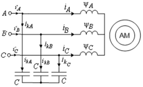
Figure 4.
Power supply diagram of IM with parallel capacitors.
Equations for the capacitors can be considered separately as the values of the voltages on them are known (Figure 4).
ukA, ukB and ukC are the phase voltages of the power supply network and C is the capacitance of the capacitors in one phase, which can have a different value.
To calculate the dynamic electromechanical processes, the above-presented DE of electrical equilibrium needs to be complemented with the equation of the rotor dynamics:
where J is the moment of inertia of the electric drive system of the unit reduced to the IM shaft, which consists of the sum of the moments of inertia of all moving parts of the SRPU with rotary or reciprocating motions; p0 is the number of pole pairs of the motor; Mc is the load torque, and Me is the electromagnetic torque of the IM, which in the three-phase coordinate system is defined by the following formula [23,24]:
where ψµA, ψµB and ψµC are the projections of the vector of the main flux linkage on the coordinate axes.
To determine the flux linkages and matrix of differential inductances of the IM circuits, which are the elements of the Jacobi matrix, characteristics of magnetization of the main magnetic path ψµ =ψµ (iµ) and paths of the leakage fluxes of the stator ψσs =ψσs (is) and rotor ψσr =ψσr (ir) are used [23,24], where
The load torque and moment of inertia of the SRPU electric drive depend on the crank angle α, which is related to the rotor angle γ by the expression
where ki is the gear ratio between the motor and output shaft of the reducing gear, which is driven with the help of the V-belt drive.
Taking into consideration the variable moment of inertia J of the unit and periodic law and changes in the load torque on the motor shaft, the DE of the motion of the rotor in the electric drive system is
The transition from the angle γ derivatives to the time derivatives is made using the formula
Changing to angle α in the Equation (4), we obtain
When integrating the system of DEs (1)–(5), the derivative dJ/dα is calculated by the numerical method and is stored in the computer memory along with the periodic dependence J = J(α). By numerical integration of DEs (1)–(5), one can study the dynamics of the electric drive system operation not only in the transient process but also in the steady-state one, which is a dynamic periodic process. The calculation of the steady-state dynamic mode does not result in a set of coordinates corresponding to a specific time coordinate but in their functional dependencies on the period of change of the torque on the IM shaft. Therefore, the calculation of the steady-state periodic mode by the evolutionary method is ineffective from many points of view. It is applicable mostly for the verification of the adopted solutions at the final stage of the analysis.
The examples of the curves of the relative value of the electromagnetic torque and motor slip s, calculated using the developed algorithm, during the starting of the SRPU electric drive based on the 4AP160S4Y3 motor with the nameplate data Pn = 15 kW, U = 220/380 V, p0 = 2, are presented in Figure 5.
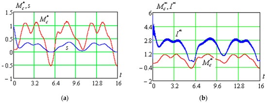
Figure 5.
The relative value of the load torque and motor slip (a) and the current and load torque (b) during SRPU starting.
The numerical integration of DEs (1)–(5) makes it possible not only to study the dynamics of the electric drive operation in the transient mode but also in the steady-state mode, which is a dynamic periodic one. As the calculation of the steady-state dynamic mode outputs not a set of coordinates corresponding to a particular time coordinate but their functional dependencies during the period of change of the IM torque, the calculation of the steady-state periodic mode using the evolutionary method is ineffective for many reasons. It is applicable only for the verification of the adopted solutions at the final stage of the analysis.
3. Steady-State Mode Calculation
Due to the fact that SRPUs have a significant response time of the moving parts, the starting modes of an IM are long-lasting, and the aperiodic components of the current go down during the first several periods of the supply voltage change. The rest of the starting mode can be regarded as quasi-periodic, i.e., it is characterised by the periodic change of currents of the stator and rotor. This allows the determination of the value of the capacitance of the capacitors needed for compensating the reactive power for each value of the slide. In the electric drive with a significant response time, the duration of the transient process is determined by the mechanical time constant, and therefore the starting process can be viewed as a set of steady-state modes.
The problem of analysis of the influence of cosine capacitors on the processes in the network supplying power to the SRPU electric drive is solved in the orthogonal axes x, y [23]. This transformation enables the description of the electromagnetic processes in IM using the minimum number of equations and does not affect the accuracy of calculations for the symmetrical machine. This approach makes it possible to reduce the volume of calculations, as the developed calculation algorithms are high-speed, allowing a real-time analysis of the processes.
The periodic dependencies of the coordinates without resorting to the calculation of the transient process can be calculated by solving a boundary value problem using the projection method developed in [24]. It consists of approximating the periodic dependencies of the coordinates by cubic splines on the network of nodes of the period, taking into consideration the periodic boundary conditions [28]. As a result, instead of a DE, we obtain a system of algebraic equations, which is their discrete analogue. The problem is solved in orthogonal coordinates, which makes it possible to avoid considering the processes within the period of supply voltage change.
The DE of electromechanical equilibrium of the SRPU electrical drive in the x, y coordinates will appear as
where ψsx, ψsy, ψ1x, ψ1y, …,ψnx, ψny, isx, isy, i1x, i1y, …, inx, iny are the flux linkages and currents of the transformed circuits of the stator (subscript s) and n equivalent circuits of the rotor (subscripts 1 − n); usx, usy are the voltages applied to the stator circuits; ω0 is the frequency of the IM supply voltage; and rs, r1–rn are the resistances of the stator winding and equivalent resistances of the rotor winding reduced to the stator winding.
The electromagnetic torque is defined using the formula
In order to shorten the presentation of the algorithm for solving the boundary value problem, the system of DE (6) is presented by one vector equation:
where
To explain the essence of the method of solving the boundary value problem, in which the basic functions are cubic splines, we plot a grid of n + 1 nodes on the period T, which makes it possible to obtain n sections, and, on each of them, we approximate the coordinates of the vector by a cubic spline of the form
where is the number of the section, which is defined by the number of the node on its right border; aj, bj, cj, dj are the coefficients of the spline.
If the step (hj = h) is uniform, the relationship between the vectors , and , the components of which are the corresponding coefficients of the spline (the superscript (*) means transposition), taking into consideration the periodicity conditions an+j = aj, bn+j = bj, and cn+j = cj, is defined by the equations
where
The vectors and are related by the equation
Therefore, instead of the system of DE (6) of the mth order, we obtain the system of mnth-order algebraic Equation (8). As , , where , are the vectors the components of which are the corresponding nodal values, the equation (8) assumes the following form:
Carrying out spline approximation of the coordinates on the grid of n nodes of the period, we obtain the algebraic analogue of the system of DE (6) in the form of a non-linear algebraic equation of the mnth order:
where H is the matrix of transition from the continuous change of the coordinates of the vector to their nodal values, the elements of which are determined solely by the grid of nodes of the period; , are the vectors made of the nodal values of the coordinates of the corresponding vectors.
For the constant slide s, the system of DE (6) is reduced to a system of non-linear algebraic equations, which in the axes x, y appear as
where the indexes sx, sy denote the connection of the flux linkages (ψ), currents (i) and active loads (r) to the corresponding stator circuits, and 1x, …, nx, 1y, …, ny denote the same for the rotor circuits; s = (ω0 − ω)/ω0 is the slide.
The complete system of equations of electrical equilibrium of the electrical circuit with parallel capacitors connected to the motor clamps (Figure 4) consists of the equations (10) and equations for the currents written based on the first Kirchhoff’s law, which in the axes x, y will appear as
where ix and iy are the components of the current in the IM power supply line; and are the components of the phase currents in the star-connected capacitors; and C is the capacitance of the capacitors in one phase.
The system of algebraic Equation (10) is non-linear. Let us present it in the vector form
where are the column vectors of flux linkages, currents and voltages (the upper index “*” means transposition).
A reliable way to find a solution of system (12) for a set value of the slide s is the parametric differentiation method [29]. For this, in system (12), the vector of the perturbing forces will be presented as the product , where ε is the scalar parameter. Differentiation of the obtained system by ε results in
where
is the Jacobi matrix of system (13), elements of which are determined according to the mathematical model of IM in the axes x, y.
After a few steps of integrating the system of DE (13) with respect to ε in the range from ε = 0 to ε = 1, we obtain the value of the vector for a set supply voltage and capacitance of the capacitors needed for a complete reactive power compensation in the power supply line, i.e., for cosφ = 1.
The initial conditions (value of the vector ) are zero because, for ε = 0, the vector of the applied voltages is equal to zero. The algorithm for calculating the static characteristics consists of two stages. In the first stage, the values of the coordinates for s = 1 are determined. In the second stage, assuming the voltage vector to be constant, we change the slide from 1 to the nominal value. This enables the iteration process convergence to be ensured, as the coordinate values obtained at the previous step satisfy the convergence condition of the iteration process.
Setting a number of values of the IM rotor slide s in the range from 1 to the nominal value, one can obtain a multidimensional static characteristic in the form of the relation between the current vector and the slide. This makes it possible to calculate the relation between the value of the capacitance of the capacitors and the slide on the condition of complete reactive power compensation, using the formula
4. Results
An example of the calculated static characteristics for the above-specified motor is presented in Figure 6.
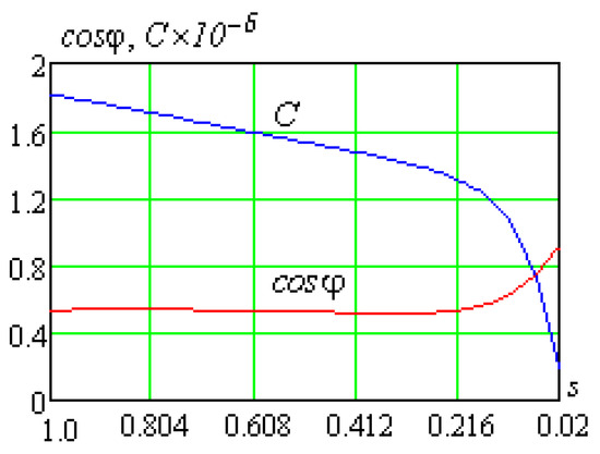
Figure 6.
The IM power factor and capacitance of the capacitors needed for complete reactive power compensation vs. slide.
The Figure 7 presents an example of calculating the curves of the electromagnetic torque, load torque and slide vs. time in the transient process of the SRPU electric drive.
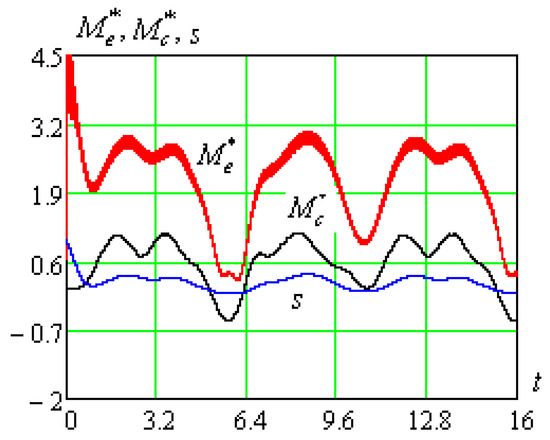
Figure 7.
The electromagnetic torque (), load torque () and rotor slide vs. time during SRPU starting.
When selecting parameters of the capacitor units, the needed power of the capacitors is calculated using the equation
where the angles φ1, φ2 are the phase shifts between the voltage and current of the unit without capacitors and with connected capacitors, respectively, and P is the active power. Thereat, the operation mode of the capacitor unit must make the operation of the unit with the capacitive power factor impossible.
The comparison of the time dependencies of the current in the power supply line with the parallel capacitors whose capacitance is regulated using the developed algorithm and without them is shown in Figure 8 and Figure 9.
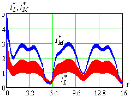
Figure 8.
The effective current in the power supply line () and at the motor input () during SRPU starting with complete reactive power compensation vs. time.
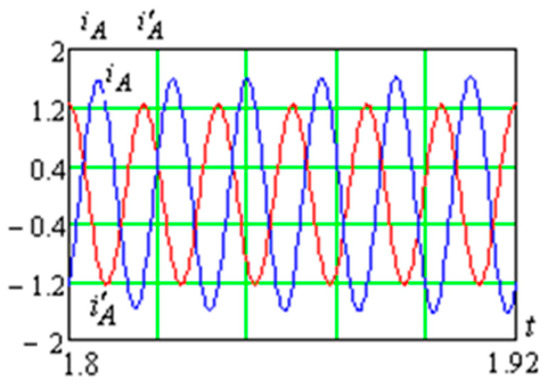
Figure 9.
The instantaneous current in phase A of the motor (iA) and in the power supply line (i’A) in the SRPU steady-state mode vs. time.
In the oil fields, it is common to cluster several SRPUs, mostly up to 16, which are powered by one transformer with a capacity of 25 to 250 kVA, connected to a 35(10) kV overhead line. Since the simultaneous switching on of all SRPUs can lead to a significant overload of the line, the proposed method is planned to be used in the future to determine the maximum permissible number of units that can be switched on at the same time.
5. Conclusions
The developed mathematical models and algorithms built on their basis enable calculation of the law of regulation of the capacity of capacitors needed for reactive power compensation in the starting and steady-state modes of SRPU operation, taking into consideration the periodically varying load on the IM torque.
The developed algorithms are based on:
- mathematical models of the IM with a high level of adequacy in-phase and orthogonal coordinates, which take into consideration the saturation of the magnetic path by the main magnetic flux and the leakage fluxes of the stator and rotor, as well as the skin-effect in the rotor;
- a mathematical model of a pump jack developed taking into consideration the geometric dimensions, kinematic diagram, and weight of the counterweights.
Regulation of the capacitance of the capacitors connected to the IM clamps is an effective way to reduce the reactive power consumption and, as a result, to considerably decrease the current in the power supply line. The developed algorithm of evaluation and regulation of the capacitance of the capacitors according to the motor load change during the whole cycle of the pump jack operation can be used as a basis for the automatic control of SRPU operation.
Author Contributions
Conceptualization, A.M.; methodology, A.M.; software, A.M.; validation, A.M. and S.C.; formal analysis, A.M. and S.C.; investigation, A.M.; resources, S.C.; data curation, A.M. and S.C.; writing—original draft preparation, A.M. and S.C.; writing—review and editing, S.C.; visualization, A.M. and S.C.; supervision, S.C.; project administration, A.M.; funding acquisition, S.C. All authors have read and agreed to the published version of the manuscript.
Funding
This research received no external funding.
Data Availability Statement
The data presented in this study are available on request from the corresponding author.
Conflicts of Interest
The authors declare no conflict of interest.
References
- Boyko, B.C. Development and Operation of Oil Fields; RealPrint: Kyiv, Ukraine, 2004; pp. 457–571. [Google Scholar]
- Mishchenko, I.T. Well Oil Extraction: Educational Aid for Universities; National University of Oil and Gas Gubkin University: Moscow, Russia, 2003; pp. 582–750. [Google Scholar]
- Pozdeev, D.A.; Kudryavtsev, S.V. ABB ALC800 intelligent station for jack pump control. Problems of Automated Electric Drive. Theory and Practice 2008, 30, 265–268. [Google Scholar]
- Pachin, M.G.; Yashin, A.N.; Bodylev, A.S.; Khakimyanov, M.I. Development of an Intelligent Control Station for Rod Pumps. J. Min. Inst. 2022, 333, 68–75. [Google Scholar] [CrossRef]
- Peng, L.; Zeng-Xiu, Z.; Chao, W.; Yi-Hui, Z. Research on Fuzzy PI Control Based on Genetic Algorithms for Beam Pumping Unit. In Proceedings of the 2014 Fourth International Conference on Instrumentation and Measurement, Computer, Communication and Control, Harbin, China, 18–20 September 2014; pp. 72–76. [Google Scholar] [CrossRef]
- Milovzorov, G.V.; Khakimyanov, M.I.; Redkina, T.A.; Milovzorov, A.G. Control system for intelligent oil wells operated by downhole method. Intell. Syst. Prod. 2015, 1, 55–58. [Google Scholar]
- Gao, M.; Tian, J.; Zhou, S.; Zhang, F. Beam-pumping unit energy-saving control system based on support vector machine. In Proceedings of the 2008 IEEE International Conference on Automation and Logistics, Qingdao, China, 1–3 September 2008; pp. 1864–1869. [Google Scholar] [CrossRef]
- Sagdatullin, A.M. Power-Efficiency Analysis of Oil Well Systems with Sucker Rod Pumping Units. Oil Gas Stud. 2015, 4, 80–84. [Google Scholar] [CrossRef]
- Sikanyika, E.W.; Wu, Z.; Mbarouk, M.S.; Mafimba, A.M.; Elbaloula, H.A.; Jiang, S. Numerical Simulation of the Oil Production Performance of Different Well Patterns with Water Injection. Energies 2023, 16, 91. [Google Scholar] [CrossRef]
- Xu, J.; Meng, S.; Li, W.; Wang, Y. Positive Torque Modulation Method and Key Technology of Conventional Beam Pumping Unit. Energies 2022, 15, 3141. [Google Scholar] [CrossRef]
- Tagirova, K.F.; Vulfin, A.M.; Ramazanov, A.R.; Fatkulov, A.A. Increasing the Efficiency of the Oil-Well Sucker-Rod Pump Operation. Neft. Khozyaystvo 2017, 7, 82–85. [Google Scholar] [CrossRef]
- Wei, J.; Gao, X. Electric-Parameter-Based Inversion of Dynamometer Card Using Hybrid Modeling for Beam Pumping System. Math. Probl. Eng. 2018, 2018, 6730905. [Google Scholar] [CrossRef]
- Khakimyanov, M.I.; Khusainov, F.F.; Shafikov, I.N. Problems of Improving the Energy Characteristics of Downhole Sucker Rod Pump Electric Drives. Electrotech. Syst. Complexes 2017, 2, 35–40. [Google Scholar] [CrossRef]
- Malko, B.D.; Popovych, V.Y.; Kharun, V.N.; Kvartsianyi, V.O. Analysis of Power Efficiency of Pump Jack Electric Motors. Rozvid. Rozrobka Naft. Hazovykh Rodovyshch 2007, 1, 49–52. [Google Scholar]
- Petrushin, V.S. Asynchronous Motors in a Variable Speed Drive; Nauka i tehnika: Odessa, Ukraine, 2006; pp. 218–233. [Google Scholar]
- Malyar, V.S.; Hamola, O.Y.; Maday, V.S.; Vasylchyshyn, I.I. Mathematical modelling of starting modes of induction motors with squirrel-cage rotor. Electr. Eng. Electromechanics 2021, 2, 9–15. [Google Scholar] [CrossRef]
- Ziuziev, A.M.; Metielkov, V.P. Estimation of the Thermal Resource of the Electric Motor of the Sucker-Rod Pumping Unit. Nauchnyye Tr. SWorld 2012, 5, 59–62. [Google Scholar]
- Mugalimov, R.G. Induction Motors with Individual Compensation of Reactive Power and Electric Drives Based on Them: Monograph; Magnitogorsk State Technical University Publisher: Magnitogorsk, Russia, 2011; pp. 71–141. [Google Scholar]
- Besarab, A.N.; Nevolnichenko, V.N.; Shabovta, M.Y. Investigation of transients with individual compensation of reactive power of an induction motor. Electr. Eng. Electr. Equip. 2007, 68, 39–44. [Google Scholar]
- Kitabov, A.N.; Abutalipov, Y.M.; Sharipov, A.I.; Khakimyanov, M.I. Estimation Of Error In Determining Electric Power Consumption During The Operation Of Rod Pumping Unit. Electrotech. Syst. Complexes 2020, 16, 5–17. [Google Scholar]
- Afliatunov, I.F. Asynchronous Electric Drive with a Capacitor Starting-Regulating Device. Ph.D. Thesis, Ulyanovsk State Technical University, Ulyanovsk, Russia, 2016. [Google Scholar]
- Andreiev, V.V.; Urazakov, K.R.; Dalimov, V.U. Oil Production Guide; Nedra-Biznestsentr: Moscow, Russia, 2000; pp. 86–184. [Google Scholar]
- Filts, R.V. Mathematical Foundations of the Theory of Electromechanical Transducers; Naukova dumka: Kyiv, Ukraine, 1979; pp. 106–172. [Google Scholar]
- Malyar, V.S.; Malyar, A.V. Mathematical Simulation of Periodic Modes of Electrotechnical Appliances. Electronnoe Model. 2005, 27, 39–53. [Google Scholar]
- Stakhiv, P.; Malyar, A. Influence of saturation and skin effect on current harmonic spectrum of asynchronous motor powered by thyristor voltage regulator. In Proceedings of the 4th International Workshop Computational Problems of Electrical Engineering, Gdynia, Poland, 1–3 June 2005; pp. 58–60. [Google Scholar]
- Shkrabets, F.P. Electric Power Supply; National Mining University Publisher: Dnipro, Ukraine, 2015; pp. 71–88. [Google Scholar]
- Michaelides, A.; Nicolaou, T. A Variable Inductor-Capacitor for Reactive Power Compensation. In Proceedings of the 13th International Symposium on Advanced Topics in Electrical Engineering (ATEE), Bucharest, Romania, 23–25 March 2023; pp. 1–6. [Google Scholar] [CrossRef]
- Malyar, A. Study of stationary modes of sucker rod pumping unit operation. Prz. Elektrotechniczny 2016, 12, 255–259. [Google Scholar] [CrossRef][Green Version]
- Yakovlev, M.N. To the solution of systems of nonlinear equations by the method of differentiation by the parameter. J. Comput. Math. Math. Phys. 1964, 4, 146–149. [Google Scholar]


Disclaimer/Publisher’s Note: The statements, opinions and data contained in all publications are solely those of the individual author(s) and contributor(s) and not of MDPI and/or the editor(s). MDPI and/or the editor(s) disclaim responsibility for any injury to people or property resulting from any ideas, methods, instructions or products referred to in the content. |
© 2023 by the authors. Licensee MDPI, Basel, Switzerland. This article is an open access article distributed under the terms and conditions of the Creative Commons Attribution (CC BY) license (https://creativecommons.org/licenses/by/4.0/).