
Exhaust Air Recovery System from the Utilisation Stage of Pneumatic System in Double Transmission Double Expansion Approach


Abstract
:1. Introduction
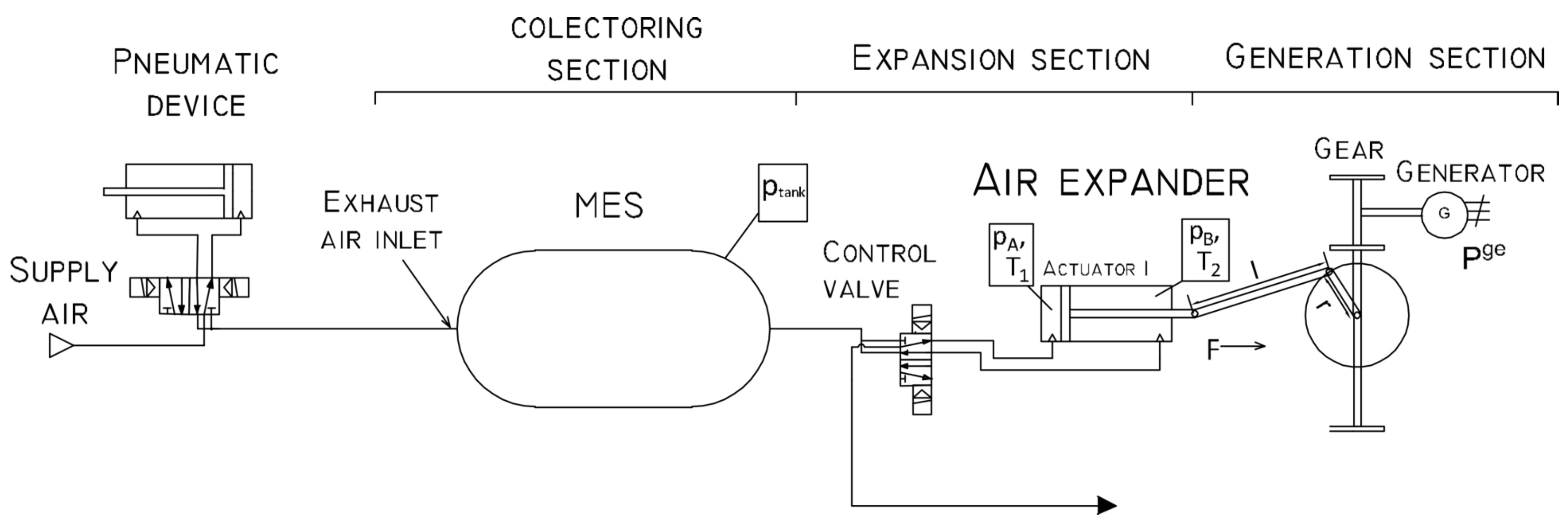
2. Theoretical Setup
- The driving torque is defined as follows:where r is the crank length, is the driving force, is the angular position of the crank, and l is the crank arm length.The bearings breaking torque is defined as follows:where and are the friction bearings coefficients.
- The resistance and electromagnetic torque is defined as follows:where K is the generator constant, I is the current, and is the rotational speed.
- The extend actuator chamber pressure is defined as follows:
- The retract actuator chamber pressure is defined as follows:
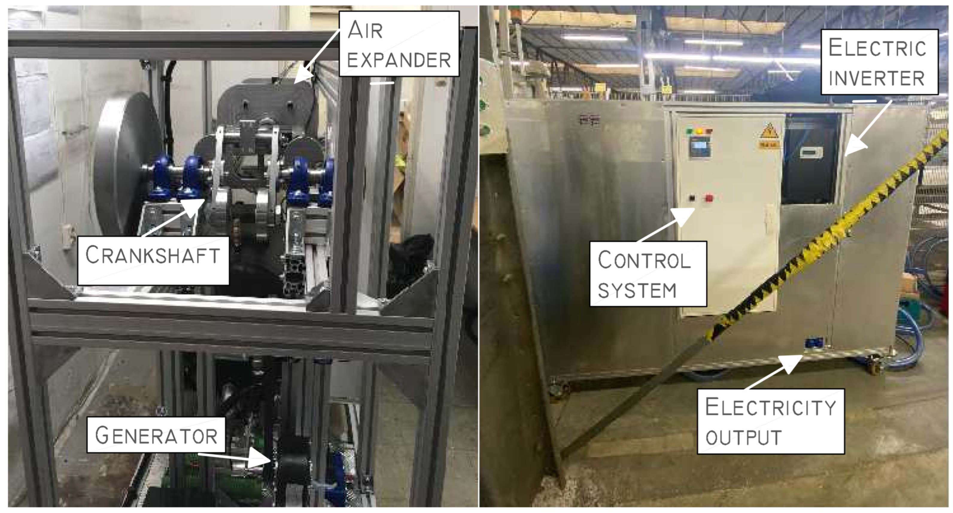
3. Experimental Setup
3.1. Laboratory Setup
3.2. Industrial Setup
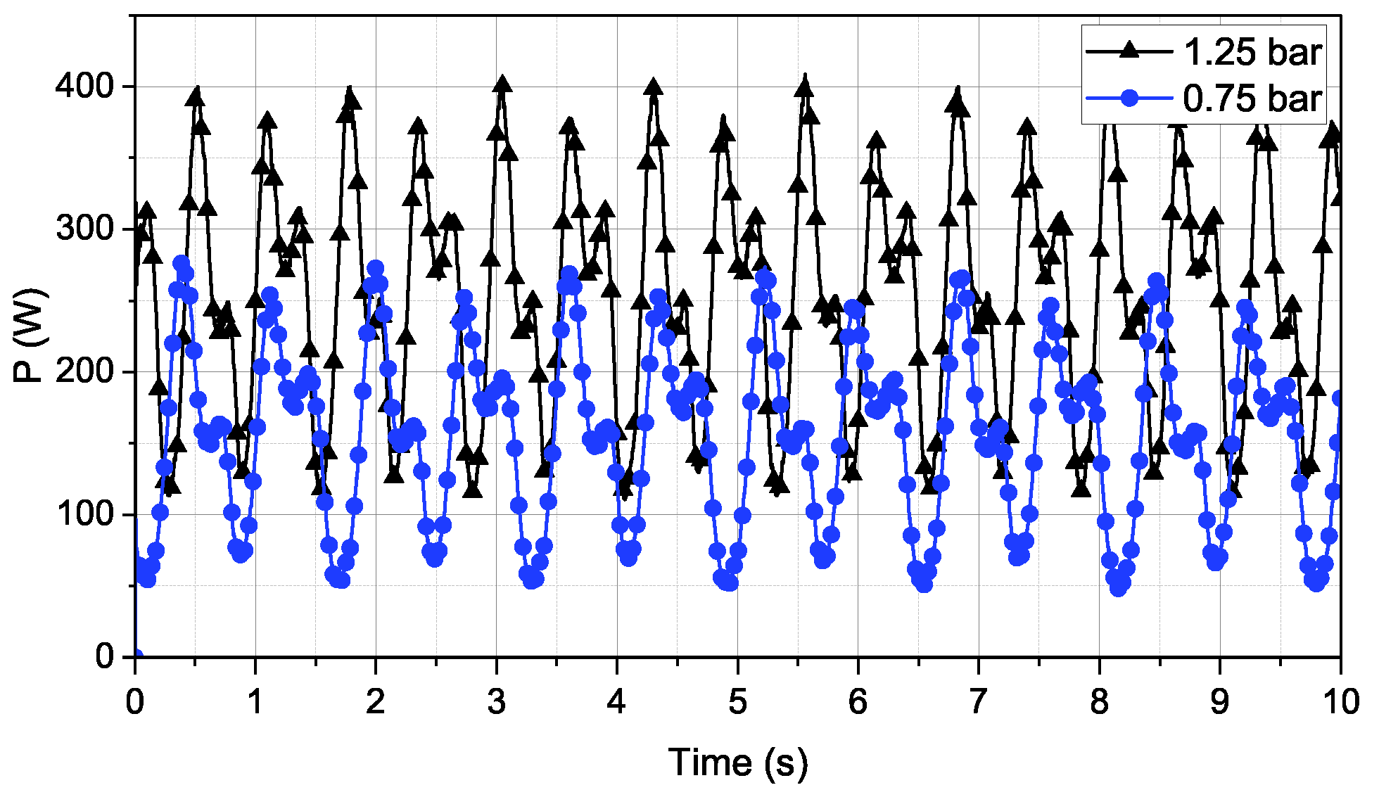
4. Results
5. Conclusions
Author Contributions
Funding
Data Availability Statement
Conflicts of Interest
References
- Caruana, L.; Refalo, P. Sustainability Analysis of a Compressed Air System. In Proceedings of the Engineering Sustainability & Sustainable Energy 2018 (ESSE ‘18) Conference, St. Paul, MN, USA, 8 May 2018. [Google Scholar]
- Nehler, T. Linking energy efficiency measures in industrial compressed air systems with non-energy benefits—A review. Renew. Sustain. Energy Rev. 2018, 89, 72–87. [Google Scholar] [CrossRef]
- Salvatori, S.; Benedetti, M.; Bonfa, F.; Introna, V.; Ubertini, S. Inter-sectorial benchmarking of compressed air generation energy performance: Methodology based on real data gathering in large and energy-intensive industrial firms. Appl. Energy 2018, 217, 266–280. [Google Scholar] [CrossRef]
- Benedetti, M.; Bonfa’, F.; Bertini, I.; Introna, V.; Ubertini, S. Explorative study on Compressed Air Systems’ energy efficiency in production and use: First steps towards the creation of a benchmarking system for large and energy-intensive industrial firms. Appl. Energy 2018, 227, 436–448. [Google Scholar] [CrossRef]
- Nourin, F.N.; Espindola, J.; Selim, O.M.; Amano, R.S. Energy, Exergy, and Emission Analysis on Industrial Air Compressors. J. Energy Resour. Technol. 2022, 144, 042104. [Google Scholar] [CrossRef]
- Dindorf, R. Estimating Potential Energy Savings in Compressed Air Systems. Procedia Eng. 2012, 39, 204–211. [Google Scholar] [CrossRef]
- Li, F.; Yu, Y.; Shu, Y.; Liu, X. Study on characteristics of photovoltaic and photothermal coupling compressed air energy storage system. Process Saf. Environ. Prot. 2023, 178, 147–155. [Google Scholar] [CrossRef]
- Mitali, J.; Dhinakaran, S.; Mohamad, A. Energy storage systems: A review. Energy Storage Sav. 2022, 1, 166–216. [Google Scholar] [CrossRef]
- Çağman, S.; Soylu, E.; Ünver, Ü. A research on the easy-to-use energy efficiency performance indicators for energy audit and energy monitoring of industrial compressed air systems. J. Clean. Prod. 2022, 365, 132698. [Google Scholar] [CrossRef]
- Hernandez-Herrera, H.; Silva-Ortega, J.I.; MartÃnez Diaz, V.L.; Sanchez, Z.G.; GarcÃa, G.G.; Escorcia, S.M.; Zarate, H.E. Energy Savings Measures in Compressed Air Systems. Int. J. Energy Econ. Policy 2020, 10, 414–422. [Google Scholar] [CrossRef]
- Leszczynski, J.S.; Grybos, D. Compensation for the complexity and over-scaling in industrial pneumatic systems by the accumulation and reuse of exhaust air. Appl. Energy 2019, 239, 1130–1141. [Google Scholar] [CrossRef]
- Mousavi, S.; Kara, S.; Kornfeld, B. Energy Efficiency of Compressed Air Systems. Procedia CIRP 2014, 15, 313–318. [Google Scholar] [CrossRef]
- Rakova, E.; Weber, J. Process Simulation of Energy Behaviour of Pneumatic Drives. Procedia Eng. 2015, 106, 149–157. [Google Scholar] [CrossRef]
- Saidur, R.; Rahim, N.A.; Hasanuzzaman, M. A review on compressed-air energy use and energy savings. Renew. Sustain. Energy Rev. 2010, 14, 1135–1153. [Google Scholar] [CrossRef]
- Cai, M.; Kawashima, K.; Kagawa, T. Power assessment of Flowing Compressed Air. Trans. ASME 2006, 128, 402–405. [Google Scholar] [CrossRef]
- Radgen, P.; Blaustein, E. Compressed Air Systems in the European Union. Energy, Emissions, Savings Potential and Policy Actions; Fraunhofer ISI: Stuttgart, Germany, 2001. [Google Scholar]
- Hepke, J.; Weber, J. Energy Saving Measures on Pneumatic Drive Systems Energy Consumption of Pneumatic Drives; Linkoping University Electronic Press: Linköping, Sweden, 2013; pp. 475–483. [Google Scholar] [CrossRef]
- Liu, C.; Kong, D.; Cai, M. Research on Energy-Saving Operation of Screw Air Compressor. Res. J. Appl. Sci. Eng. Technol. 2013, 6, 325–333. [Google Scholar] [CrossRef]
- Du, H.; Xiong, W.; Jiang, Z.; Li, Q.; Wang, L. Energy efficiency control of pneumatic actuator systems through nonlinear dynamic optimization. J. Clean. Prod. 2018, 184, 511–519. [Google Scholar] [CrossRef]
- Soylu, E.; BİlGİN, H.; Cagman, S.; Unver, U. An Ultrasonic Application to Evaluate Energy Costs of Air Leakages at the Compressed Air Systems. In Proceedings of the 2021 6th International Conference on Smart and Sustainable Technologies (SpliTech), Bol and Split, Croatia, 8–11 September 2021; pp. 1–3. [Google Scholar] [CrossRef]
- Doner, N.; Ciddi, K. Regression analysis of the operational parameters and energy-saving potential of industrial compressed air systems. Energy 2022, 252, 124030. [Google Scholar] [CrossRef]
- Fleischer, H. Manual of Pneumatic Systems Optimization; McGraw-Hill: Berlin/Heidelberg, Germany, 1995. [Google Scholar]
- Beater, P. Pneumatic Drives; Springer: Berlin/Heidelberg, Germany, 2007. [Google Scholar] [CrossRef]
- Doll, M.; Neumann, R.; Sawodny, O. Dimensioning of pneumatic cylinders for motion tasks. Int. J. Fluid Power 2015, 16, 11–24. [Google Scholar] [CrossRef]
- Raisch, A.; Sawodny, O. Analysis and optimal sizing of pneumatic drive systems for handling tasks. Mechatronics 2019, 59, 168–177. [Google Scholar] [CrossRef]
- Harris, P.G.; O’Donnell, G.E.; Whelan, T. Modelling and identification of industrial pneumatic drive system. Int. J. Adv. Manuf. Technol. 2012, 58, 1075–1086. [Google Scholar] [CrossRef]
- Gryboś, D.; Leszczyński, J.S. Double transmission double expansion technology as a method for reducing energy losses associated with oversizing of industrial compressed air systems. In Proceedings of the ECEEE Industrial Summer Study Proceedings, Gothenburg, Sweden, 14–17 September 2020; pp. 295–305. [Google Scholar]
- Doll, M.; Neumann, R.; Sawodny, O. Energy Efficient Use Of Compressed Air In Pneumatic Drive Systems For Motion Tasks. In Proceedings of the 2011 International Conference on Fluid Power and Mechatronics (FPM), Beijing, China, 17–20 August 2011; pp. 340–345. [Google Scholar] [CrossRef]
- Pfeffer, A.; Glück, T.; Schausberger, F.; Kugi, A. Control and estimation strategies for pneumatic drives with partial position information. Mechatronics 2018, 50, 259–270. [Google Scholar] [CrossRef]
- Blagojevic, V.; Jankovic, P. Advantages of restoring energy in the execution part of pneumatic system with semi-rotary actuator. Therm. Sci. 2016, 20, 1599–1609. [Google Scholar] [CrossRef]
- Raisch, A.; Hülsmann, S.; Sawodny, O. Saving Energy by Predictive Supply Air Shutoff for Pneumatic Drives. In Proceedings of the 2018 European Control Conference (ECC), Limassol, Cyprus, 12–15 June 2018; pp. 965–970. [Google Scholar] [CrossRef]
- Pfeffer, A.; Glück, T.; Kugi, A. Soft Landing and Disturbance Rejection for Pneumatic Drives with Partial Position Information. IFAC-PapersOnLine 2016, 49, 559–566. [Google Scholar] [CrossRef]
- Harris, P.; Nolan, S.; O’Donnell, G.E. Energy optimisation of pneumatic actuator systems in manufacturing. J. Clean. Prod. 2014, 72, 35–45. [Google Scholar] [CrossRef]
- Mutoh, H.; Kawasakami, Y.; Hriata, Y.; Kawai, S. An Approach to Energy Conservation in Pneumatic Systems with Meter out Circuit. In Proceedings of the 7th JFPS International Symposium on Fluid Power, Toyama, Japan, 15–18 September 2008; pp. 124–130. [Google Scholar]
- Cummins, J.J.; Nash, C.J.; Thomas, S.; Justice, A.; Mahadevan, S.; Adams, D.E.; Barth, E.J. Energy conservation in industrial pneumatics: A state model for predicting energetic savings using a novel pneumatic strain energy accumulator. Appl. Energy 2017, 198, 239–249. [Google Scholar] [CrossRef]
- Yang, F.; Tadano, K.; Li, G.; Kagawa, T. Analysis of the energy efficiency of a pneumatic booster regulator with energy recovery. Appl. Sci. 2017, 7, 816. [Google Scholar] [CrossRef]
- Li, T.C.; Wu, H.W.; Kuo, M.J. A Study of Gas Economizing Pneumatic Cylinder. J. Phys. Conf. Ser. 2006, 48, 1227–1232. [Google Scholar] [CrossRef]
- Dindorf, R.; Takosoglu, J.; Wos, P. Review of Compressed Air Receiver Tanks for Improved Energy Efficiency of Various Pneumatic Systems. Energies 2023, 16, 4153. [Google Scholar] [CrossRef]
- Raisch, A.; Sawodny, O. Energy Savings in Pneumatically Driven Plants. IEEE/ASME Trans. Mechatron. 2021, 27, 1023–1033. [Google Scholar] [CrossRef]
- Luo, X.; Sun, H.; Wang, J. An Energy Efficient Pneumatic-electrical System and Control Strategy Development. In Proceedings of the American Control Conference, San Francisco, CA, USA, 29 June–1 July 2011; pp. 4743–4748. [Google Scholar]
- Leszczynski, J.S.; Grybos, D. Sensitivity analysis of Double Transmission Double Expansion ( DTDE ) systems for assessment of the environmental impact of recovering energy waste in exhaust air from compressed air systems. Appl. Energy 2020, 278, 115696. [Google Scholar] [CrossRef]
- Leszczyński, J.S.; Gryboś, D.; Markowski, J. Analysis of optimal expansion dynamics in a reciprocating drive for a micro-CAES production system. Appl. Energy 2023, 350, 121742. [Google Scholar] [CrossRef]


| Piston Diameter [mm] | Stroke [mm] | Inlet and Outlet Connectors [inch] | Pressure Range [bar] |
|---|---|---|---|
| 32 | 20–500 | 1/8 | 1–10 |
| 40 | 25–500 | 1/4 | 1–10 |
| 50 | 25–500 | 1/4 | 1–10 |
| 63 | 25–500 | 3/8 | 1–10 |
| 80 | 25–1000 | 3/8 | 1–10 |
| 100 | 25–1000 | 1/2 | 1–10 |
| 125 | 25–1000 | 1/2 | 1–10 |
| … | … | … | … |
| Parameter | Value |
|---|---|
| Electrical Power at 1.5 bar | 450 W |
| Operating Over-Pressure | 0.75–2 bar |
| Air Consumption at 1.5 bar FAD | 750 L/min |
| Pneumatic Connection | 2xG1 |
| Electrical Connection | 230 V AC |
| Number of Phases | 1 |
| Dimensions (length × width × height) | 2.1 × 0.8 × 1.6 m |
| Approximate Weight | 400 kg |
| Piston diameter | 0.2 m |
| Piston stroke | 0.2 m |
| Connecting Rod Length, L | 0.46 m |
| Crank Radius, r | 0.1 m |
| Parameter | Value |
|---|---|
| Rated Voltage | 3 × 230/400 V AC |
| Voltage Tolerance | –20% to 15% |
| Frequency | 50/60 Hz |
| Measurement Accuracy | Class 2 (±2%) |
| Dimensions (length × width × height) | 90 × 35 × 66 mm |
| Energy Produced | Energy Self Consumed |
|---|---|
| 38.411 kWh | 7.652 kWh |
Disclaimer/Publisher’s Note: The statements, opinions and data contained in all publications are solely those of the individual author(s) and contributor(s) and not of MDPI and/or the editor(s). MDPI and/or the editor(s) disclaim responsibility for any injury to people or property resulting from any ideas, methods, instructions or products referred to in the content. |
© 2023 by the authors. Licensee MDPI, Basel, Switzerland. This article is an open access article distributed under the terms and conditions of the Creative Commons Attribution (CC BY) license (https://creativecommons.org/licenses/by/4.0/).
Share and Cite
Markowski, J.; Gryboś, D.; Leszczyński, J.; Suwa, Y. Exhaust Air Recovery System from the Utilisation Stage of Pneumatic System in Double Transmission Double Expansion Approach. Energies 2023, 16, 7840. https://doi.org/10.3390/en16237840
Markowski J, Gryboś D, Leszczyński J, Suwa Y. Exhaust Air Recovery System from the Utilisation Stage of Pneumatic System in Double Transmission Double Expansion Approach. Energies. 2023; 16(23):7840. https://doi.org/10.3390/en16237840
Chicago/Turabian StyleMarkowski, Jan, Dominik Gryboś, Jacek Leszczyński, and Yohiside Suwa. 2023. "Exhaust Air Recovery System from the Utilisation Stage of Pneumatic System in Double Transmission Double Expansion Approach" Energies 16, no. 23: 7840. https://doi.org/10.3390/en16237840
APA StyleMarkowski, J., Gryboś, D., Leszczyński, J., & Suwa, Y. (2023). Exhaust Air Recovery System from the Utilisation Stage of Pneumatic System in Double Transmission Double Expansion Approach. Energies, 16(23), 7840. https://doi.org/10.3390/en16237840