Article

Exhaust Air Recovery System from the Utilisation Stage of Pneumatic System in Double Transmission Double Expansion Approach

1
Department of Thermal and Fluid Flow Machines, Faculty of Energy and Fuels, AGH University of Krakow, Av. Mickiewicza 30, 30-059 Krakow, Poland
2
Department of Mechanical Engineering, Shibaura Institute of Technology, 3-7-5 Toyosu, Koto-ku, Tokyo 135-8548, Japan
*
Author to whom correspondence should be addressed.
Energies 2023, 16(23), 7840; https://doi.org/10.3390/en16237840
Submission received: 16 October 2023 / Revised: 17 November 2023 / Accepted: 27 November 2023 / Published: 29 November 2023
(This article belongs to the Special Issue Integration of Distributed Energy Resources (DERs))

Abstract

:
Pneumatic machines and systems are highly popular in the automation and mechanisation of production lines in many industry sectors, such as, e.g., food, automotive, production, and packaging. However, the energy efficiency of the pneumatic system is very low at about 10 to 20% The exhaust air from pneumatic machines has high energy, which is considered waste. This study introduces a novel energy recovery machine designed for integration into industrial compressed air systems. The authors describe the potential of the recovery machine within an industrial environment and present a developed exhaust air recovery system which collects exhaust air and converts it into electricity. Comprehensive industrial tests were conducted to evaluate its performance. The results, along with a detailed analysis, are presented, thereby showing there machine’s capabilities in recovering energy from compressed air processes. This research provides valuable insights into the practical implementation and benefits of deploying such energy recovery systems at an industrial scale. The findings demonstrate the machine’s potential to enhance energy efficiency and reduce operational costs in a wide array of industrial applications that are reliant on compressed air.

1. Introduction

Compressed air is very often used in industry as an energy carrier in manufacturing or technology lines. Servo motors or pneumatic actuators are powered by compressed air, which is expanded to the atmosphere after the work is done. Compressed air is also used for the operation of pneumatic equipment for spray painting and cleaning [1]. Pneumatic machines find widespread application in various industrial sectors [2,3]. Their advantages, stemming from the use of nontoxic and nonflammable fuel, make them suitable for industries like food production and mining. Still, compressed air is the most costly among typical industrial utilities [4,5]. The potential for maximising savings in pneumatic systems is substantial; however, for its implementation to be justified, it must also be economically viable [6]. That is why tests are necessary not only in the laboratory setting, but also in an industrial environment. Generally, pneumatic systems are used in applications that demand precision. High power output, simple design, and high energy density are some of the many benefits of such devices. The simplicity of pneumatic systems allows for easy adaptation and the development of configurations. As noted in [7,8], compressed air is also considered as a promising and increasingly popular energy carrier in storage systems, which are very durable and do not pollute the environment. However, the low energy efficiency of CASs (10–30%) remains a significant drawback [9,10], which often leads to them not being considered the most optimal technological solutions. The low efficiency is primarily caused by oversizing the pneumatic systems [11], thus resulting in the over-consumption of compressed air, as well as heat loss during compression [2,12], pressure drops [13], and air leaks [2,10,14]. There are numerous methods to enhance the efficiency of pneumatic systems, such as preventing energy loss [15,16], reducing energy consumption [17,18], and minimising waste energy generation [15,17,19]. Exhaust air from pneumatic devices carries a substantial amount of mechanical energy [11]. Soylu et al. [20] conducted a comprehensive study to assess the energy-saving potential of rectifying air leakages in pneumatic systems, thus revealing a substantial 42% reduction in energy costs using an ultrasonic flow meter. Doner and Ciddi [21] investigated various energy-saving strategies, including leakage elimination, compressor operation optimisation, and waste heat recovery methods. They established significant correlations between the system parameters, thereby providing valuable insights for more efficient CASs in industrial applications. Depending on the CAS specification, emphasis should be placed on reducing heat losses, reducing energy utilisation, or preventing air leakage from the system. While the reduction in compression losses and air leaks is well researched, the problem of oversizing pneumatic systems is not widely addressed.
Manufacturing companies typically offer discrete dimensions for pneumatic components. Thus, pneumatic actuators are commonly available in discrete sets of the following parameters: the piston diameter, rod diameter, and inlet/outlet diameter; these are shown in Table 1.
The standardisation of pneumatic components in the manufacturing process often limits the synergy between required operational parameters such as stroke time and generated force, as well as energy efficiency. This practice can lead to an oversizing of the pneumatic actuator and the pneumatic system, thereby resulting in an over-consumption of energy and low energy efficiency. The selection of pneumatic actuators assumes a reserve of generated force (33–50% greater than the load), which is suitable for the condition of the average piston speed in strokes from 0.3 to 0.5 m/s [11,22,23]. Furthermore, due to the discrete parameters of the actuators described above, it is not always possible to meet these requirements, and a pneumatic actuator is selected to be one size larger than the load requirement [11]. The oversizing indicator, or the pneumatic frequency ratio, was demonstrated by Doll et al. [24] and should be in between 1.1 and 1.7. Based on this indicator, Raisch and Sawodny [25] indicated the appropriate selection of pneumatic elements. The phenomenon of over-consumption of the pneumatic actuators forces the use of methods to optimise the dynamics of actuator movement to ensure appropriate automation times and save compressed air.
In the literature, three main approaches to reduce the air over-consumption of pneumatic actuators are specified: the reduction of the supply pressure amount [23,26], introduction of the back pressure [17,23,27], or use of the expansion power [19,28,29]. These approaches, respectively, involve interference in the power supply, venting, and the control of the pneumatic actuator. The most commonly used method is to reduce the supply pressure by using pressure reducers or a meter-in system (throttling the flow at the input to the actuator) and can lead to energy savings of up to 40% [17,23,26]. The expansion power utilisation in a pneumatic actuator assumes, according to Cai’s theory, the use of both transmission air power and expansion air power as opposed to the classic approach, which uses only transmission power [19,28,30,31]. The estimated energy savings of this method are up to 85% Doll et al. [28]. The idea of the method is to appropriately control the on–off signal of the pneumatic actuator from the power source through a fast switch directional control valve [29,32]. Moreover, it requires a change in the way of controlling the production process in the pneumatic machine and interference in its software. Therefore, it is difficult to use in existing pneumatic systems. As noted in [11], reused exhaust air methods are still being developed and seem very promising. The introduction of the back pressure approach has achieved energy savings of 40–75%. It involves introducing back pressure into the pneumatic actuator chamber that is currently being vented. The most widely used method for regulating the piston speed and actuator stroke time is the so-called metering system, that is, to throttle the actuator air flow [23,33,34]. This method increases the complexity of the entire pneumatic system, and energy savings are calculated to be up to 5%. The exhaust air recovery system works on the principle of a spring, in which exhaust air from the extend movement is used for the piston retract movement [17]. Energy savings are estimated at 43%; the additional investment cost is 83% of the cost of a classic pneumatic system. Cummins et al. [35] presented the idea of staging a pneumatic system (high- and low-pressure) using an isobaric air tank and achieved energy savings of 32 to 78%. Another method is a closed pneumatic system in which exhaust air is pumped to the low pressure tank and then compressed back to the pneumatic system using a booster [36,37]. Researchers achieved energy savings of up to 40%. Dindorf et al. [38] presented a method for improving the efficiency of CASs with the development of a tank charging and discharge system. They explored compressed air receiver tanks (CARTs) and highlighted their potential to enhance energy efficiency in pneumatic systems.
Raisch and Sawodny [39] introduced a cascade system, which consists of a high- and low-pressure subsystem that achieved air savings of 65%. Luo et al. [40] used a vane-type air expander for exhaust air and converted air energy into electricity. They gained energy savings of 15–23% at a back pressure of 3.5 bar. Leszczynski and Grybos [11,41] proposed that methods that involve the staging of the pneumatic system should be classified as a double transmission, double expansion solution.
This paper presents a system for recovering waste energy from compressed air and converting it into electricity, which is called the exhaust air recovery system. Its implementations in industrial infrastructure are shown. The novelty of this paper is focused on a holistic approach to reduce the over-consumption of the pneumatic system, because instead of focusing on one actuator as in the abovementioned methods, the whole or part of the pneumatic system is considered. As a result, the complexity of the system does not increase as rapidly as in other solutions. The research carried out allows for the analysis of the process and the real benefits resulting from the use of energy recovery technology.

2. Theoretical Setup

As noted in [15], in CASs, most of the useful energy in the pneumatic system is obtained through transmission energy, while expansion energy is practically lost with the exhaust air. The authors in [15] described the air power in the compressed state as follows:
P A = p A V ˙ ln p A p 0
where p A is the compressed air pressure, V is the volume, and p 0 is the ambient pressure
The transmission air power P T describes the isobaric transformation work of the volume change in the actuator at a constant pressure:
P T = p A p 0 V ˙ A
where p A is the compressed air pressure, p 0 is the ambient pressure, and V ˙ A is the volume flow.
The single transmission single expansion (STSE) power P E is related to the pressure change of the exhaust air during isothermal transformation:
P E = p A V ˙ A ln p A p 0 + p 0 p A 1
The solution proposed by the authors [41] is called double transmission double expansion (DTDE), which increases the share of expansion power during the operation of the pneumatic actuator. It involves capturing the expansion power from a high-pressure actuator and then using it in another low-pressure actuator. When the double transmission double expansion approach of the pneumatic system is installed, the utilisation stage of the compressed air is divided into high- and low-pressure stages with interpressures defined as p b . In the high-pressure stage, compressed air converts transmission power into piston movment, as force is created until it reaches the end position in the pneumatic machine. In this case, air is expanded from the supply pressure to the back pressure p b . Without the DTDE approach, compressed air is exhausted into the atmosphere. With the DTDE approach, compressed air flows further into the tank at a pressure of p b and expands in the low-pressure stage of the pneumatic system, such as, for example, from the energy recovery system into the ambient environment. This results in partial recovery of the expansion power from the exhaust air. By collecting the exhausted air from the pneumatic system, we create a system for reutilising compressed air. The exhaust air recovery system comprises a tank, pneumatic valves, pneumatic actuator, a set of mechanical transmissions, and a permanent magnet synchronous generator (PMSG). The pneumatic system with the DTDE approach and energy recovery system is presented in Figure 1 and has been divided into three sections: collectoring, expansion, and generation. Compressed air exhausted from pneumatic devices is collected in the collectoring section. As a result of the installed exhaust air collector with nonreturn valves, the air from several pneumatic machines flows into the storage tank. The next two sections of expansion and generation contain an exhaust air recovery system consisting of control valves, a piston expander, and a electrical generator. In the expansion section, air is sequentially expanded in the expander chambers and then released into the atmosphere. Then, the mechanical energy of the compressed air is converted into electrical energy through the reciprocating motion of the expander piston and the electrical generator.
By capturing and converting the energy from the exhaust air, our system offers the potential for significant energy savings and increased overall efficiency in pneumatic systems. This technology can help reduce the environmental impact of pneumatic processes by minimising energy waste and improving resource utilisation.
A mathematical model of the expander–generator unit was created to determine the device’s operating parameters. The authors in [42] conducted an in-depth analysis of the dynamics of compressed air expansion in the pneumatic piston engine system, thereby describing each of the processes occurring in the CAS. The model of the unit was formulated according to [42] in the form of the differential equations presented below.
J d 2 α d t 2 = i = 1 i = 3 T i ω = d α d t L d I d t = K ω R 1 + R 2 I
where J is the moment of inertia, α is the angular position of the crank, t is the time, T is the torque, ω is the angular speed, L is the generator inductance, K is the generator constant, R is the generator resistance, and I is the current.dditionally, the torque values resulting from the force applied to the actuator piston and braking torques were determined:
  • The driving torque is defined as follows:
    T 1 = r F sin α ( r l ) 2 sin 2 α + r l cos α 1 ( r l ) 2 sin 2 α 1
    where r is the crank length, F d r i v e is the driving force, α is the angular position of the crank, and l is the crank arm length.The bearings breaking torque is defined as follows:
    T 2 = C 0 + C 1 ( ω ) 3 2 sgn ( ω )
    where C 0 and C 1 are the friction bearings coefficients.
  • The resistance and electromagnetic torque is defined as follows:
    T 3 = 3 2 K I sgn ( ω )
    where K is the generator constant, I is the current, and ω is the rotational speed.
The driving force is described as follows:
F d r i v e = p A A 1 p B A 1 A 2 p C A 2
where p A is the pressure in the first chamber, p B is the pressure in the second chamber, p C is the ambient pressure, A 1 defines the piston cross-sections, and A 2 defines the piston rod cross-section.he cross-section of the piston is defined as follows:
A i = π D i 2 4
for i = 1 and i = 2.
The pressures are calculated as follows:
  • The extend actuator chamber pressure is defined as follows:
    p A = R x T 1 m 1 ( 1 ( R x R w ) ϕ p s ( T 1 ) p 0 ) V 1
  • The retract actuator chamber pressure is defined as follows:
    p B = R x T 2 m 2 ( 1 ( R x R w ) ϕ p s ( T 2 ) p 0 ) V 2
where R x is the air constant, T is the temperature, m is the air mass, ϕ is the relative air humidity, R w is the vapour constant, p s is the saturation pressure, p 0 is the ambient pressure, and V is the volume.
We calculate the electrical power of the generator P G as follows:
P G = R 1 I 2
where R 1 is the generator resistance, and I is the current.

3. Experimental Setup

The experiments were carried out in two laboratory and industrial environments; the setups are described below.

3.1. Laboratory Setup

At an industrial scale, recovery could only take place after a thorough analysis of the pneumatic machine from which the air was being collected. Such an analysis ensured that the operation of the device was not significantly disturbed, i.e., it did not significantly affect the dynamics of filling and emptying the actuator or the time and speed of the piston. Adjusting the exhaust air collector system prevents back pressure, which affects the dynamics of the piston in the cylinder and may prevent the chamber from emptying freely. The energy recovery machine (see, Figure 1) was connected to the exhaust of the industrial devices through a collecting system. The air was collected and stored in a 100 L capacity tank. As soon as the over-pressure in the tank reached p t a n k = 1.25 bar, a sensor sent a signal to a logic controller, which then initiated the control of pneumatic valve switching. Compressed air entered the actuator chamber, thereby applying a force F to the piston and causing piston displacement to the actuator’s dead point. Then, the valves were switched, with one chamber being emptied, while the other was powered by compressed air. The linear motion of the piston was converted into rotary motion using a crankshaft assembly connected to a shaft. The shaft was linked through belt transmissions to a permanent magnet synchronous generator (PMSG), thereby generating electrical energy. The machine operated until the pressure in the tank dropped to p 0 = 0.75 bar above atmospheric pressure.
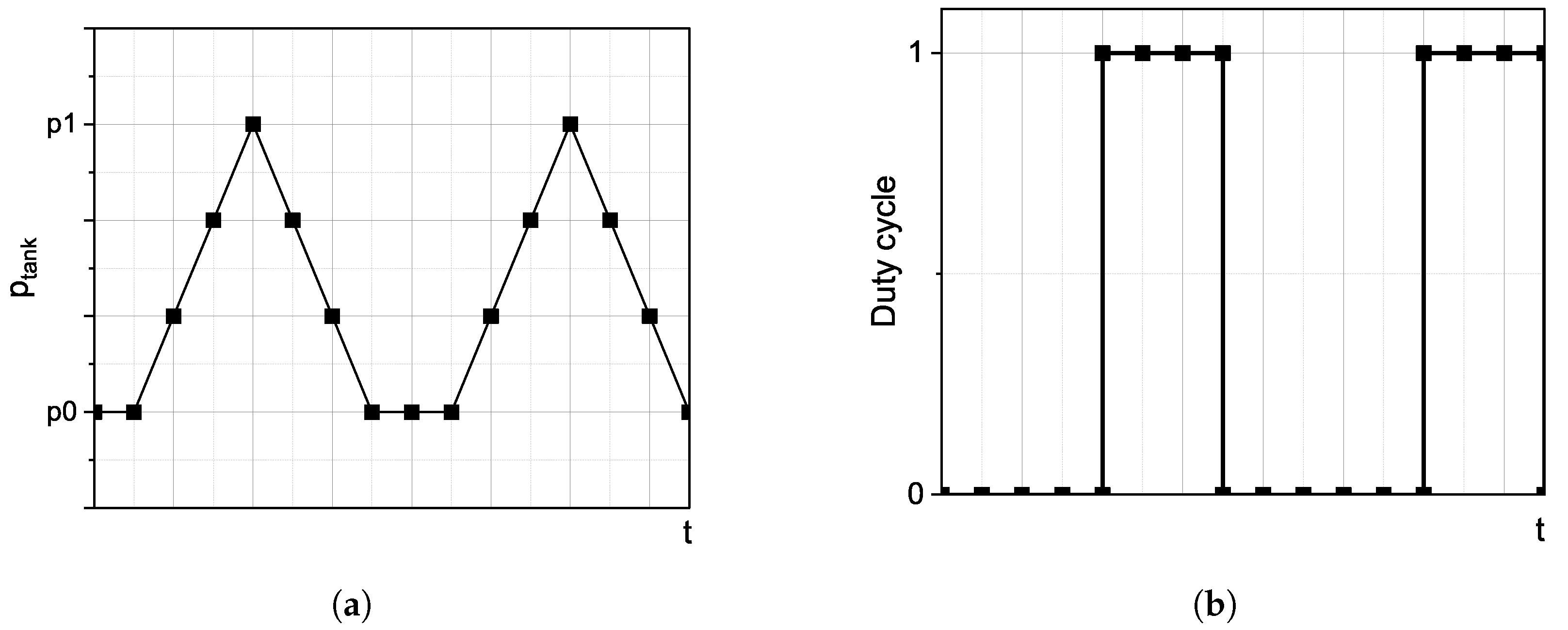
The following Figure 2 shows the compressed air collection scheme over time and the machine’s operating mode. Here, p 0 denotes the minimum working over-pressure of the machine, and p 1 represents the pressure at which the machine begins its operation. Due to the lack of continuous supply of compressed air to the tank, the machine operated intermittently. The system often operated only in startup mode, thereby resulting in significant power fluctuations. This intermittent duty cycle is visible in the chart below, where value labeled as 0 signifies the machine’s idle mode, where the tank is being charged, or where it is waiting for a load, whereas 1 signifies the working mode in which the expander chambers are sequentially powered, and current is generated in generating section.
Table 2 presents construction parameters of one linear drive from expansion section of recovery unit and set of conditions within which recovery machine can function effectively and safely. This includes factors like electrical power, operating pressure, air consumption, pneumatic connections, and many other relevant variables that define the operational limits or boundaries of the machine. For a proper and safe use of the machinery, it is crucial to obtain these values.

3.2. Industrial Setup

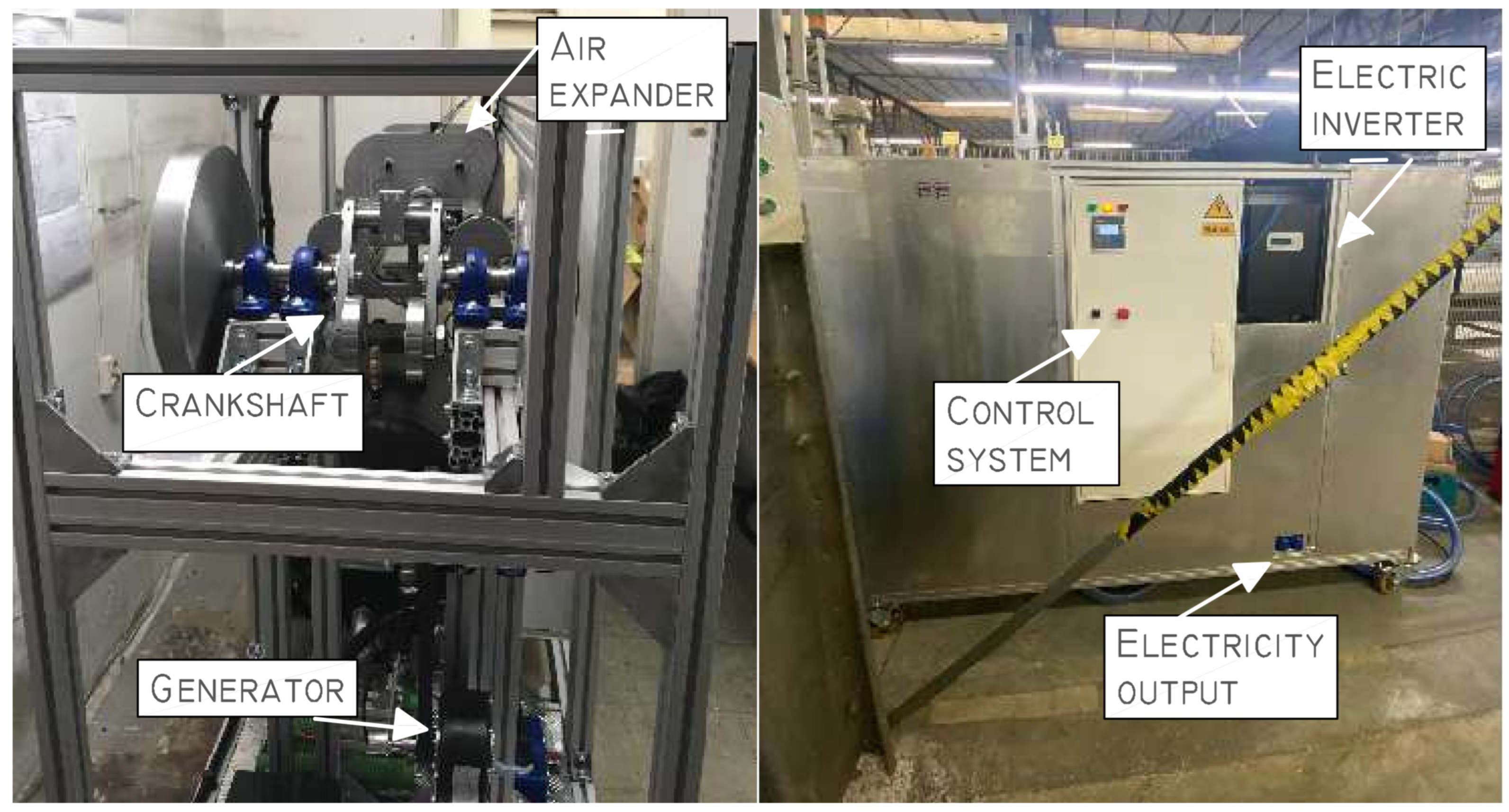
To evaluate the performance of our device, an industrial test was conducted on a semitechnical scale. During the test, the machine’s operation, its impact on processes along the production line, and the resulting energy savings were examined. This test aimed to validate the effectiveness of our air recovery system in real-world production environments. Figure 3 shows the energy recovery system installed in an industrial environment. The machine’s arrangement and the collection system through pipes connected to the compressed air tank are visible.
The collection system aims to capture the exhaust air from the outlets of pneumatic devices in industrial area and then accumulate it in the tank of the recovery system for reutilisation. This is achieved by replacing existing pneumatic mufflers with tubes equipped with nonreturn valves through which air is transported to the expansion collector and then to the storage tank. The dimensions of the pneumatic lines and the capacity of the expansion collector are chosen so that the system installation does not adversely affect the operation of the devices from which the air is sourced. Exhaust air collector is shown in Figure 4a.
The continuity of supplying exhaust air depends on the work frequency of machines from which the air is collected. The most effective solution would be to connect as many devices as possible that operate continuously. This way, we would ensure a continuous supply of air and constant back pressure in the tank, thereby allowing for the continuous operation of the piston expander with constant electrical power. This solution only requires additional pneumatic lines from pneumatic machines to expand the collecting system.
To conduct electric energy measurements, an MEW-01 meter was installed. This electric energy monitor enables the monitoring of energy consumption through a wireless network. The Table 3 below presents the technical data of the applied component.

4. Results

The selection of the appropriate installation was carried out, among other things, thanks to the characteristics of the expander’s operation shown below. Figure 5 presents the power, volume flow, efficiency, and actuator force versus the rotational speed of the generator.
It is observed that, at lower speeds, the machine generated less power, which increased with higher rotational speeds, reached its peak, and then decreased again. This is due to a higher air flow rate, which delivers a greater amount of energy. With a higher rotational speed, the compressed air engine consumes a larger mass of air, which can be critical in terms of energy efficiency, especially if air resources are limited. With a gauge pressure of 2 bar, the system can achieve maximum average power output ranging around 600 W. The highest efficiency of the exhaust air recovery system was 20% for the rotational speed between 300 and 350 rpm. Working with a gauge pressure of 1.0 bar, an average generated power of 200 W was obtained at the point of maximum efficiency. The low efficiency of the device resulted from the low efficiency of the expander and its undeveloped construction, thus meaning that a single actuator or an immature air supply control system was used. In practice, optimal pneumatic engine speeds must be selected to ensure adequate power for a given application while not exceeding air consumption. The other solution could be inefficient or incapable of reaching the required power. This is a crucial element in the design and optimisation of pneumatic systems, thus having a significant impact on their performance and effectiveness.
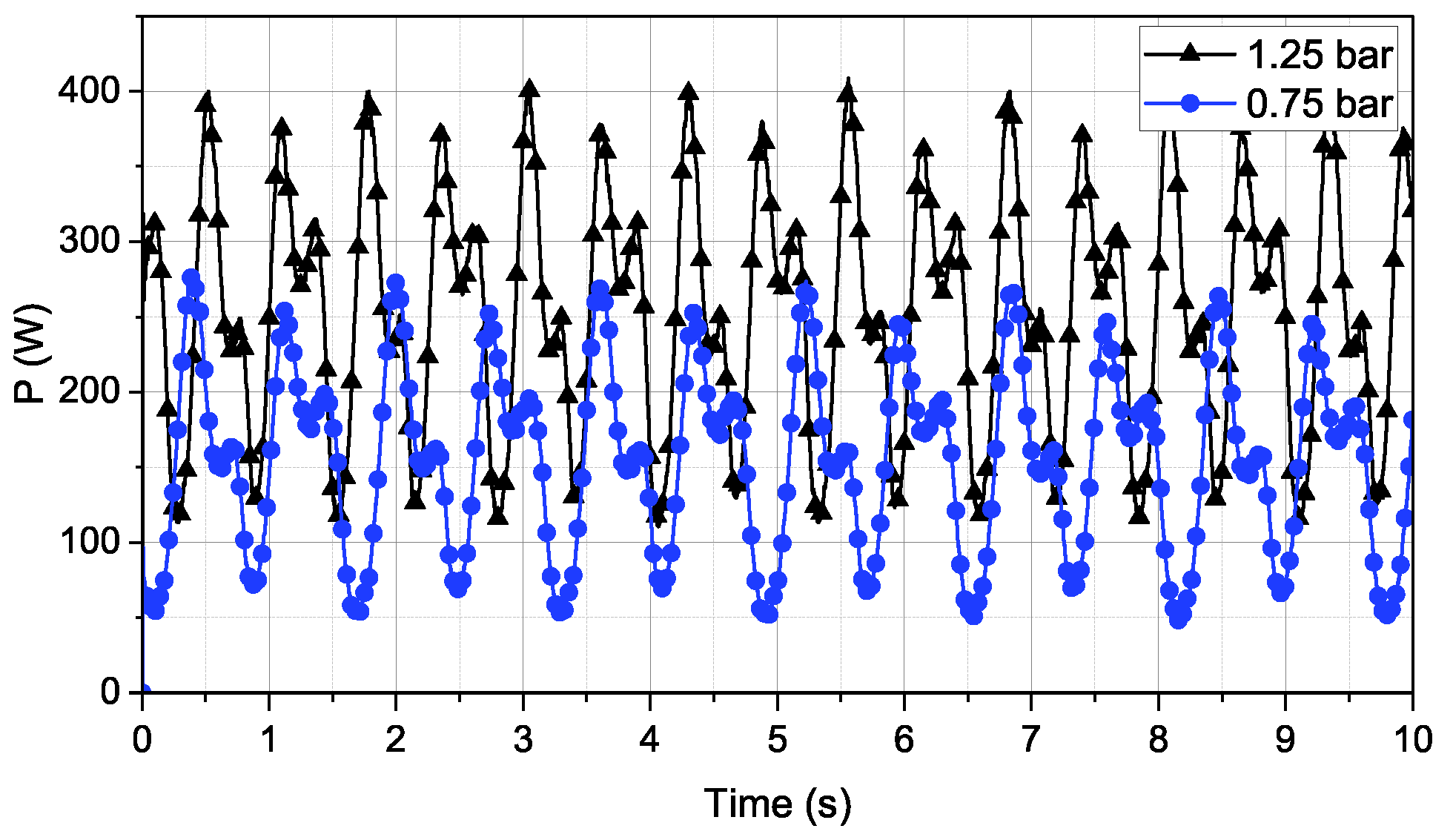
Figure 6 shows the performance characteristics of the recovery machine working with supply pressures of 1.25 bar, as well as 0.75 and 5.6 ohm of generator load.
During the industrial tests, the machine operated within this range of pressures. Due to utilisation through a single-cylinder expander, significant power fluctuations were observed, despite the incorporation of a flywheel. The fluctuations in the power output are inherent to the operation of a single-cylinder expander, as it experiences variations in pressure and velocity during each cycle. It has an impact on the overall stability of the system, thus leading to inconsistent power generation. Power fluctuations can potentially be smoothed out by employing a multicylinder design. This represents another step in the potential development of the energy recovery machine leading to enhance the efficiency and effectiveness of the energy recovery machine. As the operation cycle of the energy recovery machine is based on utilising air that is cyclically supplied from pneumatic devices, this causes the machine to not operate with a constant pressure. With the consumption of air from the tank, the supply pressure drops, and consequently, the generated power decreases. It can be expected that the power curve will not only deviate from the above characteristics, but also that the power will decrease over time along with the pressure in the tank.
The following figures, Figure 7 and Figure 8, show the machine’s performance in the industrial environment.
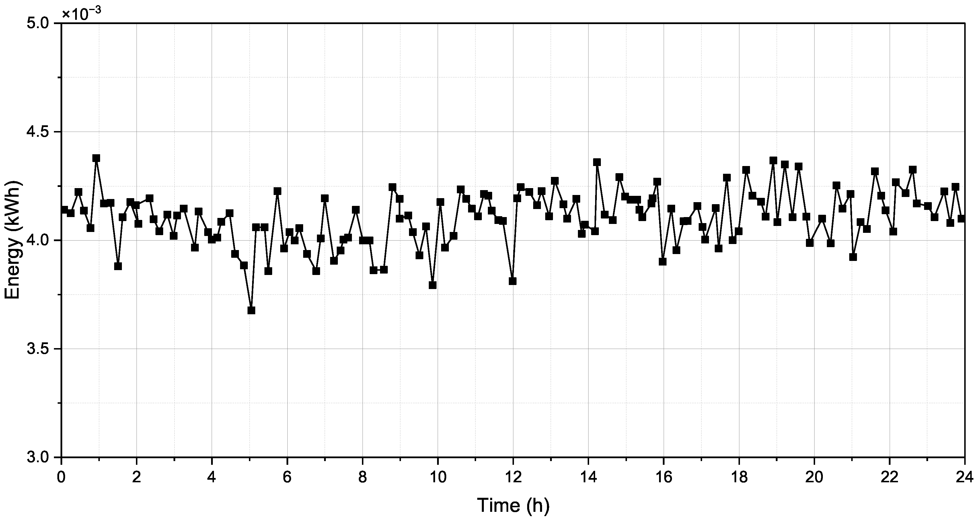
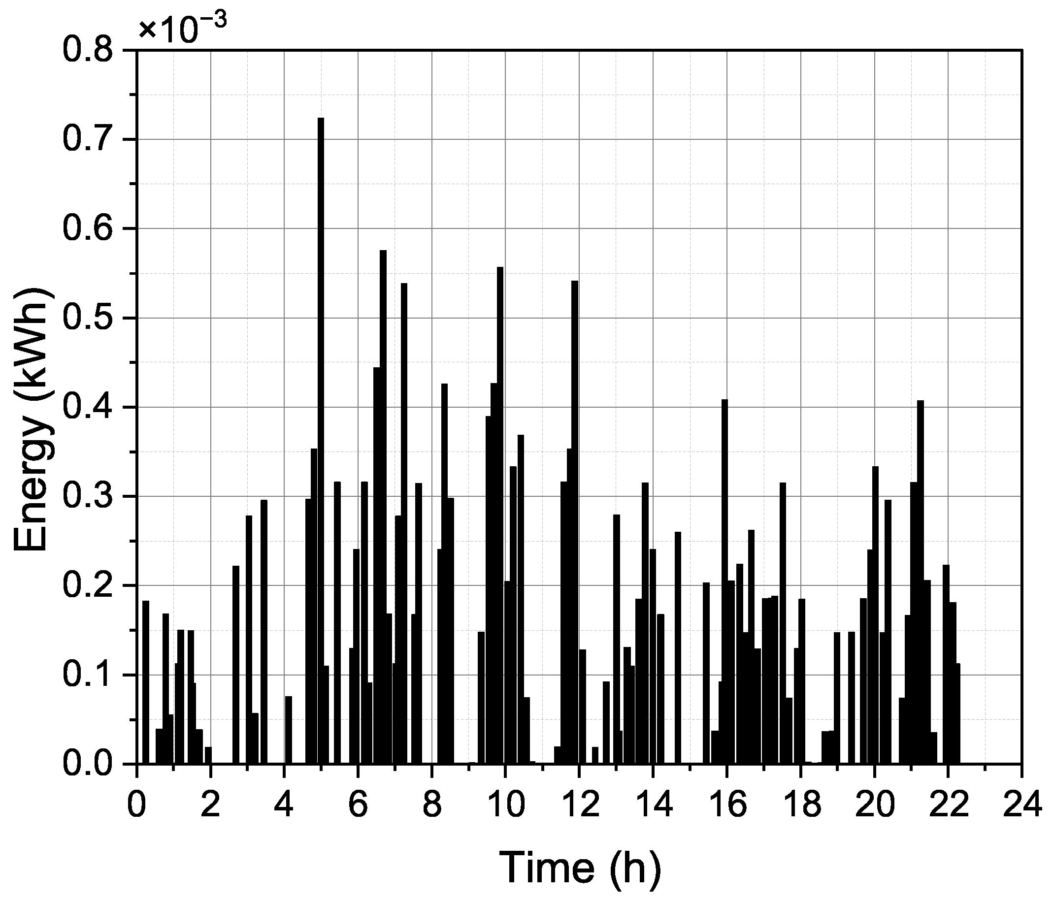
For better clarity, the results from a full day of machine operation have been presented. Over the course of 24 h, the machine operated intermittently and generated electrical energy, which was monitored by the energy meter.The energy generated by the recovery machine over 24 h is presented in Figure 7. During a 24 h period, the machine’s tank was powered by compressed air exhausted from the pneumatic devices. Installing the energy recovery machine allowed for the reutilisation of compressed air that would otherwise be considered waste. By generating electrical energy throughout the entire day, the recovery machine contributes to increasing the efficiency of the entire industrial plant, regardless of the amount of energy generated. The small energy values seen on the graph are associated with the low amount of waste air and the machine’s intermittent operation. The device not only can operate at a low supply pressure and low mass flow rate of air, but is also flexible for the variety of the mass flow when emptying of the tank. This solution allows for the effective adjustment of the machine operation according to variable conditions, which is particularly beneficial in the context of the instability of the mass flow during tank emptying.
Figure 8 illustrates the self-consumed energy by the recovery machine over a 24 h period. It is important to note that the machine only consumes energy for powering the inverter and the control system. However, in order for the system to be constantly prepared to perform its function, it must consume a small, steady amount of energy even when the expander is not in operation, thus meaning energy is not being generated. The substantial surplus of generated energy compared to the consumed energy is evident. Despite this, the outcomes may not be considered to be overwhelmingly favorable. The interruptions in the tank supply, attributed to an imperfect collection system, resulted in periods of machine downtime. This led to intermittent operation, often in startup mode, which tended to have lower efficiency levels. The fluctuations in the graph depicting the generated energy indicate operation with a variable mass flow and pressure levels oscillating between p 1 and p 0 . Nevertheless, the findings strongly suggest the potential for energy recovery in the pneumatic systems. One can see the precise energy values in Table 4.
The results of the energy recovery system installed in an industrial environment are noteworthy. The machine generated a total of 38.411 kWh of energy while consuming only 7.652 kWh. The visible surplus of generated energy over consumed energy indicates the effectiveness of the machine. Depending on the purpose, the recovered energy can be used within the facility where the machine is installed to improve the overall efficiency of the industrial facility or can be sent back to the electrical grid to optimise the costs of electricity.

5. Conclusions

The article presents the construction, scheme, and description of a compressed air energy recovery machine. Both laboratory experiments and industrial and tests have been carried out. These tests allowed for an assessment of the performance and demonstrated the applicability of such devices in the industry. It is worth noting that implementing such a system does not disrupt the simultaneous operation of the device, which is critical for the continuity of industrial processes. The recovery machine was connected to the compressed air outlet from pneumatic devices through a special collector system. Therefore, it used exhaust air that would otherwise be considered waste and expended into the surroundings. Our pneumatic unit introduced the second stage of transmission and expansion, thereby creating the DTDE (double transmission double expansion) system.
The results achieved by the energy recovery machine can be considered a success. The energy produced was over five times greater than that energy that was self-consumed by the machine. It produced 38,411 kWh of energy that directly contributes to increasing the efficiency of the entire industrial facility. Its low value is likely caused by an underdeveloped collecting system at the location where the prototype was installed, which caused intermittent machine operation often in the startup mode. Intermittent operation of the recovery system also negatively affected its efficiency. The need for the device to be constantly ready to perform work requires constant power supply and, consequently, constant electricity consumption despite a standstill. The value of 7.652 kWh was, therefore, mainly the result of the energy used to maintain the readiness of the recovery system and not its consumption during machine operation.
These findings are important for striving towards a more efficient and sustainable use of energy in the pneumatic industry. In summary, the conducted tests open new perspectives for the utilisation of energy recovery in pneumatic installations and show that, with further research and enhancements, even greater savings and environmental benefits can be expected. Further research will focus on the improvement of the collection system and the increase in the expander efficiency. Expanding the collector system to connect more pneumatic machines will allow for the collection of a larger volume of air and ensure the continuous operation of the energy recovery machine. In addition, it will be possible to achieve higher pressure in the collector tank, thereby resulting in more power generated. The efficiency of the air expander can be increased by expanding the construction, for example, by using a multicylinder expander. This will also result in stable generated power during operation. The additional use of waste heat to provide heating during the expansion process would also positively impact the efficiency of the entire system.

Author Contributions

Conceptualisation, J.L. and D.G.; methodology J.L., D.G. and Y.S.; formal analysis, J.L., D.G., Y.S. and J.M.; resources, J.M.; writing—original draft preparation, J.M. writing—review and editing, J.L. and D.G.; visualisation, J.M. All authors have read and agreed to the published version of the manuscript.

Funding

The work was carried out as part of a research subvention under contract no. 16.16.210.476, which was supported by the Polish Ministry of Science and Higher Education and by the Polish National Agency for Aca- demic Exchange under the Strategic Partnerships Program, Project No. BPI/PST/2021/1/00023. The research project was supported by the program “Excellence Initiative – Research University” for the AGH University of Krakow.

Data Availability Statement

Data is contained within the article.

Conflicts of Interest

The authors declare no conflict of interest.

References

  1. Caruana, L.; Refalo, P. Sustainability Analysis of a Compressed Air System. In Proceedings of the Engineering Sustainability & Sustainable Energy 2018 (ESSE ‘18) Conference, St. Paul, MN, USA, 8 May 2018. [Google Scholar]
  2. Nehler, T. Linking energy efficiency measures in industrial compressed air systems with non-energy benefits—A review. Renew. Sustain. Energy Rev. 2018, 89, 72–87. [Google Scholar] [CrossRef]
  3. Salvatori, S.; Benedetti, M.; Bonfa, F.; Introna, V.; Ubertini, S. Inter-sectorial benchmarking of compressed air generation energy performance: Methodology based on real data gathering in large and energy-intensive industrial firms. Appl. Energy 2018, 217, 266–280. [Google Scholar] [CrossRef]
  4. Benedetti, M.; Bonfa’, F.; Bertini, I.; Introna, V.; Ubertini, S. Explorative study on Compressed Air Systems’ energy efficiency in production and use: First steps towards the creation of a benchmarking system for large and energy-intensive industrial firms. Appl. Energy 2018, 227, 436–448. [Google Scholar] [CrossRef]
  5. Nourin, F.N.; Espindola, J.; Selim, O.M.; Amano, R.S. Energy, Exergy, and Emission Analysis on Industrial Air Compressors. J. Energy Resour. Technol. 2022, 144, 042104. [Google Scholar] [CrossRef]
  6. Dindorf, R. Estimating Potential Energy Savings in Compressed Air Systems. Procedia Eng. 2012, 39, 204–211. [Google Scholar] [CrossRef]
  7. Li, F.; Yu, Y.; Shu, Y.; Liu, X. Study on characteristics of photovoltaic and photothermal coupling compressed air energy storage system. Process Saf. Environ. Prot. 2023, 178, 147–155. [Google Scholar] [CrossRef]
  8. Mitali, J.; Dhinakaran, S.; Mohamad, A. Energy storage systems: A review. Energy Storage Sav. 2022, 1, 166–216. [Google Scholar] [CrossRef]
  9. Çağman, S.; Soylu, E.; Ünver, Ü. A research on the easy-to-use energy efficiency performance indicators for energy audit and energy monitoring of industrial compressed air systems. J. Clean. Prod. 2022, 365, 132698. [Google Scholar] [CrossRef]
  10. Hernandez-Herrera, H.; Silva-Ortega, J.I.; MartÃnez Diaz, V.L.; Sanchez, Z.G.; GarcÃa, G.G.; Escorcia, S.M.; Zarate, H.E. Energy Savings Measures in Compressed Air Systems. Int. J. Energy Econ. Policy 2020, 10, 414–422. [Google Scholar] [CrossRef]
  11. Leszczynski, J.S.; Grybos, D. Compensation for the complexity and over-scaling in industrial pneumatic systems by the accumulation and reuse of exhaust air. Appl. Energy 2019, 239, 1130–1141. [Google Scholar] [CrossRef]
  12. Mousavi, S.; Kara, S.; Kornfeld, B. Energy Efficiency of Compressed Air Systems. Procedia CIRP 2014, 15, 313–318. [Google Scholar] [CrossRef]
  13. Rakova, E.; Weber, J. Process Simulation of Energy Behaviour of Pneumatic Drives. Procedia Eng. 2015, 106, 149–157. [Google Scholar] [CrossRef]
  14. Saidur, R.; Rahim, N.A.; Hasanuzzaman, M. A review on compressed-air energy use and energy savings. Renew. Sustain. Energy Rev. 2010, 14, 1135–1153. [Google Scholar] [CrossRef]
  15. Cai, M.; Kawashima, K.; Kagawa, T. Power assessment of Flowing Compressed Air. Trans. ASME 2006, 128, 402–405. [Google Scholar] [CrossRef]
  16. Radgen, P.; Blaustein, E. Compressed Air Systems in the European Union. Energy, Emissions, Savings Potential and Policy Actions; Fraunhofer ISI: Stuttgart, Germany, 2001. [Google Scholar]
  17. Hepke, J.; Weber, J. Energy Saving Measures on Pneumatic Drive Systems Energy Consumption of Pneumatic Drives; Linkoping University Electronic Press: Linköping, Sweden, 2013; pp. 475–483. [Google Scholar] [CrossRef]
  18. Liu, C.; Kong, D.; Cai, M. Research on Energy-Saving Operation of Screw Air Compressor. Res. J. Appl. Sci. Eng. Technol. 2013, 6, 325–333. [Google Scholar] [CrossRef]
  19. Du, H.; Xiong, W.; Jiang, Z.; Li, Q.; Wang, L. Energy efficiency control of pneumatic actuator systems through nonlinear dynamic optimization. J. Clean. Prod. 2018, 184, 511–519. [Google Scholar] [CrossRef]
  20. Soylu, E.; BİlGİN, H.; Cagman, S.; Unver, U. An Ultrasonic Application to Evaluate Energy Costs of Air Leakages at the Compressed Air Systems. In Proceedings of the 2021 6th International Conference on Smart and Sustainable Technologies (SpliTech), Bol and Split, Croatia, 8–11 September 2021; pp. 1–3. [Google Scholar] [CrossRef]
  21. Doner, N.; Ciddi, K. Regression analysis of the operational parameters and energy-saving potential of industrial compressed air systems. Energy 2022, 252, 124030. [Google Scholar] [CrossRef]
  22. Fleischer, H. Manual of Pneumatic Systems Optimization; McGraw-Hill: Berlin/Heidelberg, Germany, 1995. [Google Scholar]
  23. Beater, P. Pneumatic Drives; Springer: Berlin/Heidelberg, Germany, 2007. [Google Scholar] [CrossRef]
  24. Doll, M.; Neumann, R.; Sawodny, O. Dimensioning of pneumatic cylinders for motion tasks. Int. J. Fluid Power 2015, 16, 11–24. [Google Scholar] [CrossRef]
  25. Raisch, A.; Sawodny, O. Analysis and optimal sizing of pneumatic drive systems for handling tasks. Mechatronics 2019, 59, 168–177. [Google Scholar] [CrossRef]
  26. Harris, P.G.; O’Donnell, G.E.; Whelan, T. Modelling and identification of industrial pneumatic drive system. Int. J. Adv. Manuf. Technol. 2012, 58, 1075–1086. [Google Scholar] [CrossRef]
  27. Gryboś, D.; Leszczyński, J.S. Double transmission double expansion technology as a method for reducing energy losses associated with oversizing of industrial compressed air systems. In Proceedings of the ECEEE Industrial Summer Study Proceedings, Gothenburg, Sweden, 14–17 September 2020; pp. 295–305. [Google Scholar]
  28. Doll, M.; Neumann, R.; Sawodny, O. Energy Efficient Use Of Compressed Air In Pneumatic Drive Systems For Motion Tasks. In Proceedings of the 2011 International Conference on Fluid Power and Mechatronics (FPM), Beijing, China, 17–20 August 2011; pp. 340–345. [Google Scholar] [CrossRef]
  29. Pfeffer, A.; Glück, T.; Schausberger, F.; Kugi, A. Control and estimation strategies for pneumatic drives with partial position information. Mechatronics 2018, 50, 259–270. [Google Scholar] [CrossRef]
  30. Blagojevic, V.; Jankovic, P. Advantages of restoring energy in the execution part of pneumatic system with semi-rotary actuator. Therm. Sci. 2016, 20, 1599–1609. [Google Scholar] [CrossRef]
  31. Raisch, A.; Hülsmann, S.; Sawodny, O. Saving Energy by Predictive Supply Air Shutoff for Pneumatic Drives. In Proceedings of the 2018 European Control Conference (ECC), Limassol, Cyprus, 12–15 June 2018; pp. 965–970. [Google Scholar] [CrossRef]
  32. Pfeffer, A.; Glück, T.; Kugi, A. Soft Landing and Disturbance Rejection for Pneumatic Drives with Partial Position Information. IFAC-PapersOnLine 2016, 49, 559–566. [Google Scholar] [CrossRef]
  33. Harris, P.; Nolan, S.; O’Donnell, G.E. Energy optimisation of pneumatic actuator systems in manufacturing. J. Clean. Prod. 2014, 72, 35–45. [Google Scholar] [CrossRef]
  34. Mutoh, H.; Kawasakami, Y.; Hriata, Y.; Kawai, S. An Approach to Energy Conservation in Pneumatic Systems with Meter out Circuit. In Proceedings of the 7th JFPS International Symposium on Fluid Power, Toyama, Japan, 15–18 September 2008; pp. 124–130. [Google Scholar]
  35. Cummins, J.J.; Nash, C.J.; Thomas, S.; Justice, A.; Mahadevan, S.; Adams, D.E.; Barth, E.J. Energy conservation in industrial pneumatics: A state model for predicting energetic savings using a novel pneumatic strain energy accumulator. Appl. Energy 2017, 198, 239–249. [Google Scholar] [CrossRef]
  36. Yang, F.; Tadano, K.; Li, G.; Kagawa, T. Analysis of the energy efficiency of a pneumatic booster regulator with energy recovery. Appl. Sci. 2017, 7, 816. [Google Scholar] [CrossRef]
  37. Li, T.C.; Wu, H.W.; Kuo, M.J. A Study of Gas Economizing Pneumatic Cylinder. J. Phys. Conf. Ser. 2006, 48, 1227–1232. [Google Scholar] [CrossRef]
  38. Dindorf, R.; Takosoglu, J.; Wos, P. Review of Compressed Air Receiver Tanks for Improved Energy Efficiency of Various Pneumatic Systems. Energies 2023, 16, 4153. [Google Scholar] [CrossRef]
  39. Raisch, A.; Sawodny, O. Energy Savings in Pneumatically Driven Plants. IEEE/ASME Trans. Mechatron. 2021, 27, 1023–1033. [Google Scholar] [CrossRef]
  40. Luo, X.; Sun, H.; Wang, J. An Energy Efficient Pneumatic-electrical System and Control Strategy Development. In Proceedings of the American Control Conference, San Francisco, CA, USA, 29 June–1 July 2011; pp. 4743–4748. [Google Scholar]
  41. Leszczynski, J.S.; Grybos, D. Sensitivity analysis of Double Transmission Double Expansion ( DTDE ) systems for assessment of the environmental impact of recovering energy waste in exhaust air from compressed air systems. Appl. Energy 2020, 278, 115696. [Google Scholar] [CrossRef]
  42. Leszczyński, J.S.; Gryboś, D.; Markowski, J. Analysis of optimal expansion dynamics in a reciprocating drive for a micro-CAES production system. Appl. Energy 2023, 350, 121742. [Google Scholar] [CrossRef]
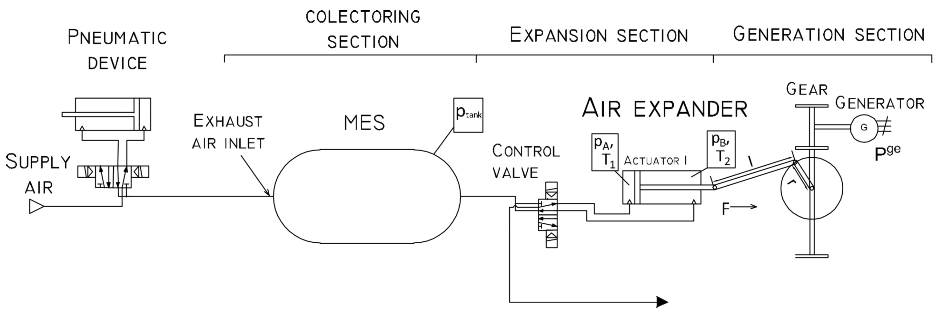
Figure 1. Topology of energy recovery system in double transmission double expansion approach.
Energies 16 07840 g001
Figure 2. Compressed air collection (a) and machine’s duty cycle (b).
Energies 16 07840 g002
Figure 3. Energy recovery system installed in an industrial environment.
Energies 16 07840 g003
Figure 4. Industrial setup scheme (a) and exhaust air collecting system (b). In the diagram, 1 is the exhaust air inlet, 2 is the valve manifold, 3 is the exhaust air outlet, 4 is the inlet of exhaust air to collector, 5 is the collector, and 6 is the outlet to energy recovery machine.
Energies 16 07840 g004
Figure 5. Operation characteristics of energy recovery system: (a) power generated versus the rotational speed of the generator; (b) volume flow of air versus the rotational speed; (c) efficiency versus the rotational speed; (d) actuator force versus the rotational. speed.
Energies 16 07840 g005
Figure 6. Performance characteristics of the recovery machine for 1.25 bar and 0.75 bar of supply pressures.
Energies 16 07840 g006
Figure 7. Energy generated by the machine over a period of 24 h.
Energies 16 07840 g007
Figure 8. Energy of self-consumption of the machine over a period of 24 h.
Energies 16 07840 g008
Table 1. Classic dimensions for pneumatic actuator.
Piston Diameter [mm]Stroke [mm]Inlet and Outlet Connectors [inch]Pressure Range [bar]
3220–5001/81–10
4025–5001/41–10
5025–5001/41–10
6325–5003/81–10
8025–10003/81–10
10025–10001/21–10
12525–10001/21–10
Table 2. Operating and construction parameters of recovery machine.
ParameterValue
Electrical Power at 1.5 bar450 W
Operating Over-Pressure0.75–2 bar
Air Consumption at 1.5 bar FAD750 L/min
Pneumatic Connection2xG1
Electrical Connection230 V AC
Number of Phases1
Dimensions (length × width × height)2.1 × 0.8 × 1.6 m
Approximate Weight400 kg
Piston diameter0.2 m
Piston stroke0.2 m
Connecting Rod Length, L0.46 m
Crank Radius, r0.1 m
Table 3. Electric energy monitor’s technical data.
ParameterValue
Rated Voltage3 × 230/400 V AC
Voltage Tolerance–20% to 15%
Frequency50/60 Hz
Measurement AccuracyClass 2 (±2%)
Dimensions (length × width × height)90 × 35 × 66 mm
Table 4. Results of energy recovering system installed in industrial environment.
Energy ProducedEnergy Self Consumed
38.411 kWh7.652 kWh
Disclaimer/Publisher’s Note: The statements, opinions and data contained in all publications are solely those of the individual author(s) and contributor(s) and not of MDPI and/or the editor(s). MDPI and/or the editor(s) disclaim responsibility for any injury to people or property resulting from any ideas, methods, instructions or products referred to in the content.