1. Introduction
The docking of a ship in a floating dock is typically carried out at the quay of a ship repair yard. The floating dock is submerged to a depth which enables the ship to enter. Once in the dock, the ship is picked up and raised together with the dock. The same reverse technique is applied to allow the ship to leave the dock. This method of docking requires that the depth of water be sufficient for the dock to be lowered to an appropriate depth, determined by the dimensions of the dock and the ship size.
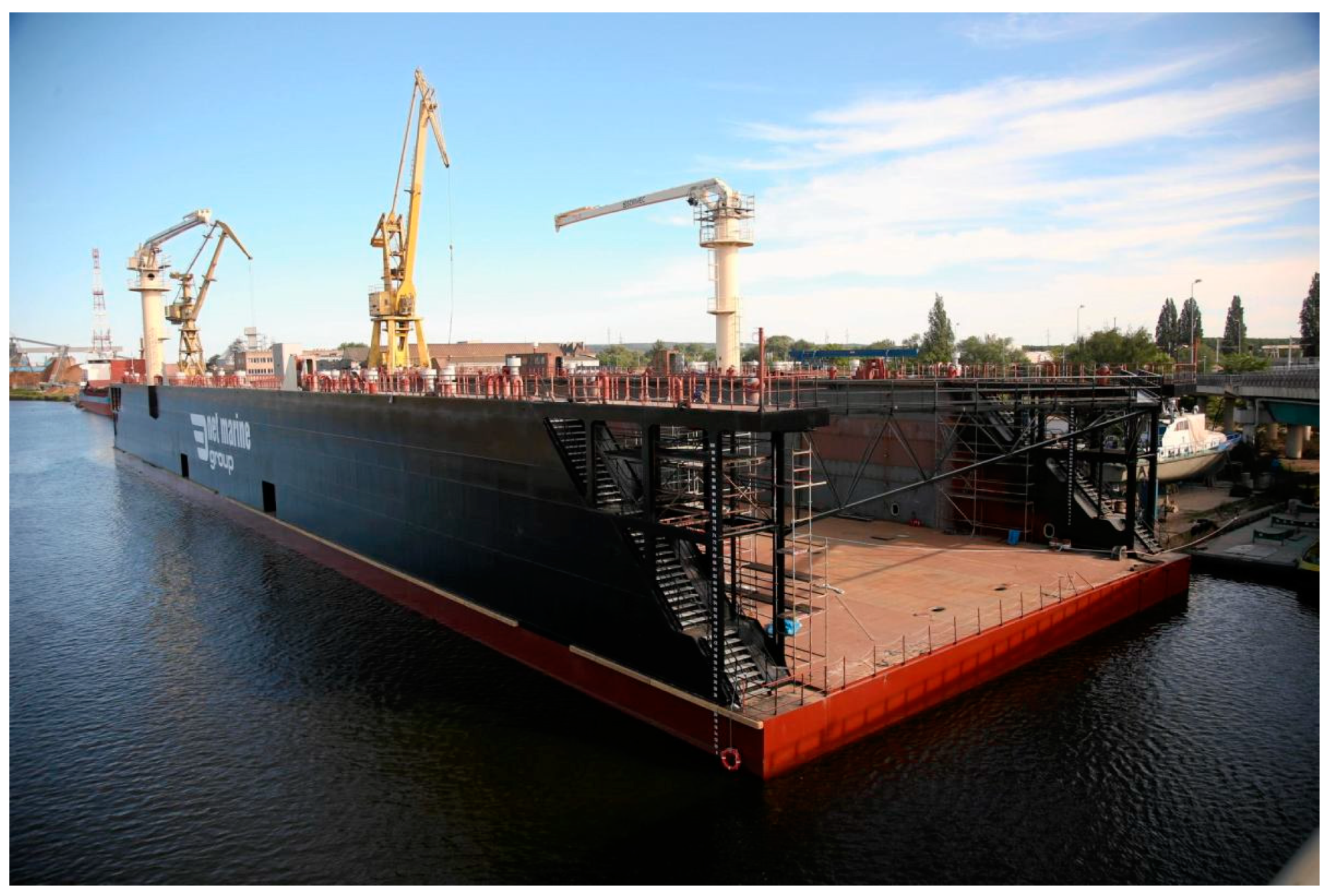
A floating dock (
Figure 1) was built at the Pomerania Repair Yard (Szczecin, Poland) and dimensions to dock maximum size vessels which are permitted to enter the Parnicki Canal.
The dimensions of the dock and the maximum size of docked vessels are shown in
Table 1. The dimensions of the Parnicki Canal are shown in
Table 2.
Figure 2 shows the location of the Pomerania Ship Repair Yard and the dock at the Parnicki Canal [
3].
2. Aim and Scope of Research
It is evident from the data presented in
Table 1 and
Table 2 that the Parnicki Canal can be navigated by vessels with a maximum draught of 6.0 m. However, the water depth at the Repair Quay is too shallow for the dock to submerge and carry out ship docking. In order for a vessel to be docked at the quay, the canal at the quay would have to be deepened to a minimum of 11 m over a bottom surface area larger than the dock. Although technically possible, the water engineering works would be highly costly, as the deepening of the canal would have to be accompanied by the construction of a new quay for the deepened canal. Alternatively, a dock trench has been built along the centre line of the canal, at a cost lower than that of building a new quay and deepening the canal alongside. The decision to build the dock depth was taken at the same time as the construction of the floating dock. The dimensions of the dock trench are shown in
Table 3 [
4,
5].
In order to dock a ship in the dock trench, a system must be built to move the dock away from the quay and over the dock trench and stabilise the dock in position during docking. To this end, a research and development agreement was concluded between the Pomerania Repair Yard and the Maritime University of Szczecin to carry out analyses and research work on the feasibility of building such a system.
This study is aimed to develop an innovative system to move the dock and stabilise it in position during ship docking operations at the dock trench built on the Parnicki Canal.
The operations of moving the dock and ship docking are shown in
Figure 3 [
6].
In the sparse literature on floating docks, the focus is made primarily on dock design and construction or dock strength and stability.
In [
7], various floating docks, their construction, design principles, methods of calculating dock stresses and strength, and ballast systems have been discussed. In [
8], two design concepts of an environmentally friendly dock have been presented, with the environmental aspect examined in the context of repairing the ship’s hull. Dock design procedures have also been discussed in [
9,
10]. Stability of a floating dock at different stages of lowering and raising of the same has been studied in [
11,
12]. In [
13,
14,
15,
16], results of strength analyses of floating docks, also under wave action, have been presented and their application in the design process has been analysed. The safety assessment of floating dock structures during docking operations by the finite element method has been carried out in [
17].
An in-depth analysis of the literature has not revealed any description of methods or applications of systems for moving the dock from the quay to the dock trench or stabilising the dock in position during ship docking operations. No information on the use of green, renewable energy sources or the storage of green energy in order to power systems for moving and stabilising a floating dock has been found either.
In view of the above, the authors’ approach to the design and construction of an environmentally friendly dock moving and stabilisation system (PSPD) can be considered novel and contributing to the environmental protection.
3. Requirements and Design Criteria for the Dock Moving and Stabilisation System
In order to achieve the key research goal, it is necessary to:
Determine specific requirements for the dock moving and stabilisation system;
Determine the weather conditions under which a ship can be docked;
Determine criteria for the dock moving and stabilisation system;
Design the system and ensure that it meets all of the requirements and design criteria;
Examine the environmental impact of the system—intended to be environmentally friendly, neither the dock nor the dock moving and stabilisation system can adversely affect the natural environment.
Considering that port tugboats could be employed to move and stabilise the dock, the last task mentioned above is of great importance. Apart from the fact that operation of a tugboat is highly costly, fitted with an internal combustion engine, a tugboat will emit large amounts of exhaust fumes during long hours of operation while moving the dock and stabilising it in position during docking operations. Any adverse change in weather parameters (e.g., increased wind speed) would necessitate the engagement of tugboats with a higher propulsion power, which would in turn generate even more exhaust fumes.
The dock moving and stabilisation system must be designed to be powered by green energy from renewable sources.
The system requirements and design criteria are shown in
Table 4.
Achievement of the research goal, i.e., the development of a dock moving and stabilisation (PSPD) system which meets the requirements and criteria listed in
Table 4, is shown in a flowchart in
Figure 4.
4. External Forces Acting on the Dock Moving System
The dock, whether empty or with a docking ship, will be subject to external forces from the environment, such as the wind, river current, wave action, drag force acting on the dock while it is being moved, or impact of the ship entering the dock. All of them will simultaneously constitute effective loads acting on the PSPD system. The PSPD system will be designed and analysed for such loads, taking into account the safety factor.
The research and analysis of various variants of the PSPD system will be conducted for two extreme positions of the dock:
Elevated, with a ship onboard;
Submerged, with a ship onboard.
All external forces will be calculated for the two dock positions, and the PSPD systems will be designed and their technical and operational parameters analysed for the corresponding external loads.
Apart from wind and river current, the dock will be subject to the drag force generated while being moved from the Repair Quay to the dock trench, as well as the drag force generated by the ship being pulled into the dock. The wave action on the Parnicki Canal is slight, and therefore its effect on the dock is negligible. The external forces are shown in
Figure 5.
4.1. River Current Forces Acting on the Dock
Vessels will be docked in a canal with a longitudinal flow of water (river current), represented by a longitudinal force
RCx (
Figure 5). Its value is calculated from the following formula:
where:
ρw—water density, ρw = 1000 kg/m3 (fresh water),
Sx(T)—surface area of the submerged dock’s bow for draft T,
CCx—dock’s bow drag factor,
CH—shallow water impact factor,
Vc(T)—speed of the river current for draft T.
The measured average current speed
Vc = 0.5 knots (0.26 m/s) has been applied for the calculations [
5]. The distribution of the transverse underwater surface of the dock has been calculated on the basis of the dock design documentation (
Figure 6) [
2].
Based on the numerical analyses of distribution of the river current speed
Vc (
T) in the canal in the dock trench area, it has been established that water speed variability in the dock area is negligible. Therefore, a constant water speed has been assumed for the purpose of calculation of force
RCx. Detailed results of the numerical calculations are included in [
6].
The longitudinal forces of river current acting on the dock
RCx for current speed
Vc = 0.5 knots (0.26 m/s), calculated from Equation (1), are shown in
Table 5.
A detailed description of the calculations performed is included in [
6].
4.2. Wind Impact on the Dock
Wind is a random phenomenon in time and space. On the basis of many years of measurements of wind force and direction in the Port of Szczecin [
18,
19,
20], it has been established that the probability of wind occurrence from a particular direction is highly variable.
Table 6 shows the results of wind measurements, broken down by force (in °B) and directions [
19].
Figure 7 shows the probability of wind occurrence from a specific geographical direction and the geographical location of the dock.
The most unfavourable wind direction (the greatest impact of the wind) is when the wind blows against the side of the dock and ship. The statistics (
Figure 7) show that the lateral wind direction relative to the dock is NE and SW. The probability of a NE wind is very low, and that of a SW wind (from the Repair Quay) is close to zero.
An analysis of all of the criteria and requirements, as well as the port regulations applicable to ship docking operations, has led to an assumption that the system for moving and stabilising the dock during docking operations will be designed taking into consideration the impact of wind on the dock, calculated for:
The average wind speed corresponding to a wind force of 5 °B,
Any direction (angle βA) of wind action on the dock.
The impact of wind on the dock (
Figure 5) has been calculated from the following equations:
where:
ρA—air density,
CAx, CAy, CMz—aerodynamic drag coefficient for the dock empty or with a ship,
Ax(H)—transverse distribution of the dock’s surface above water as a function of the lateral height H of the dock,
Ay(H)—longitudinal distribution of the dock’s lateral surface above water as a function of the lateral height H of the dock,
VA(H)—distribution of wind speed as a function of the lateral height H of the dock, calculated from Equations (3),
L—dock’s length.
The wind speed distribution
VA(
H) has been calculated from the following formula:
where:
VAZ—average wind speed at height ‘z’,
VA10—average wind speed at a height of, e.g., 10 m,
Z—the height for which VAZ is calculated (in this case, Z is the lateral height H of the dock, measured from the water surface),
α—the exponent depending on the area (land, water) over which the wind blows; it depends on the so-called roughness of the surface.
Applicable regulations specify various values of
α, depending on the area. For the purpose of calculation of the impact of wind on the floating dock,
α = 0.17, as defined in the DNV rules and standards, will apply [
21].
Distributions of the dock’s bow surface above water and lateral surface above water as a function of its lateral height H, for the dock with a ship, are shown in
Figure 8 and
Figure 9.
The results of the calculation of wind impact for different wind speeds, corresponding to wind force expressed in °B, for wind direction relative to the dock
βA = 0–180° (
Figure 5) are shown in
Figure 10 and
Figure 11.
4.3. Drag Force Acting on the Dock While Being Moved
Being moved from the quay to the dock trench or back to the quay, the dock will be subject to a lateral drag force. Based on the estimated dock transit time of maximum 30 min and the established distance at which the dock will be moved, the speed of dock transit has been calculated. The dock will only be moved submerged to a draft of T = 2 m.
The lateral drag force
RDy (
Figure 6) has been calculated from the following formula:
where:
ρw—water density,
Sy—lateral surface of the dock below the waterline, while being moved (T = 2 m),
Vy—speed of dock transit,
CDy—hydrodynamic drag coefficient when moving the dock.
The calculated values of the lateral drag force
RDy for the estimated dock transit time and the calculated dock transit speeds are shown in
Table 7.
4.4. Drag Force Acting on the Vessel Being Pulled into the Dock
When the docked vessel is connected by ropes to the system for pulling the vessel into the dock, additional external forces will be exerted on the dock from the drag of the vessel being pulled in. Although the speed at which the ship’s hull is pulled into the dock will be very low, the effect of the river current on the ship’s hull must also be taken into account in the calculation of the resistance of the ship’s hull. Water speed
VR relative to the vessel’s hull has been taken into consideration in the calculation of the drag force
RSx acting on the vessel being pulled in:
where:
VS—absolute speed of the vessel being pulled in,
VC—speed of the river current.
The results of the calculation of drag force
RSx are shown in
Table 8.
4.5. Total External Forces Acting on the Dock
Table 9 shows the total maximum external forces acting on the dock empty and with a vessel, for different wind speeds (°B) and for drafts
T = 2 m and
T = 10 m, taking into account the force from the river current, the drag force of dock while being moved, and the drag force of the vessel being pulled in (
Figure 5).
5. Design Concepts of a System for Autonomous Movement and Stabilisation of the Dock
Three initial design concepts of a system for moving and stabilising the dock in position have been developed:
A waterjet-based system, utilising a ballast system installed on the dock;
A rope winch-based system;
A hydraulically driven mechanical system.
Conceptual designs for each system and possible different variants of the same have been developed. Preliminary strength calculations as well as calculations related to the capability of moving the dock at maximum weather conditions have been performed. An analysis for meeting the criteria and requirements shown in
Table 4 has been performed for each of the systems and their respective variants.
5.1. Waterjet-Based System
The floating dock is equipped with a ballast system for submerging and raising the dock. The ballast system has four pumps (two on the starboard and two on the port side of the dock) of the following parameters:
In order to engage the ballast system in moving the dock, each ballast pump is required to suck water from under the dock and jet it through a suitable nozzle mounted on the side of the dock below the waterline for the minimum dock draft. To this end, the ballast system must be fitted with the following items, mounted in the vicinity of each pump:
Additional valves (gate valves) for disconnecting the ballast system,
Additional nozzles for jetting the pumped water,
Additional short piping connecting the nozzles to the pump, with additional valves.
The pumps and additional valves should be controlled in the same way as during the dock ballasting.
Two variants have been developed for this system, one with directional nozzles and one with fixed nozzles (
Figure 12).
Directional nozzles allow the water jet and the resulting thrust force to be pointed in any direction, while fixed nozzles only allow the water jet to be pointed in one, y-axis direction while the dock is being moved. The latter solution requires additional devices to generate longitudinal thrust forces.
Thrust forces which can be generated, depending on the diameter of the discharge nozzle, have been calculated for each pump (
Table 10).
This results from a comparison of the obtained values of thrust forces from one nozzle with the external forces acting on the dock (
Table 9) that the system would only be capable of moving the dock at low wind speeds. Two nozzles on one side of the dock can be used simultaneously to move the dock. Moreover, since the design does not provide for the counteracting of longitudinal forces (
Rx), the system would have to be supported by another system capable of balancing forces from the ‘x’ direction. Last but not least, the system cannot guarantee that stabilising the dock during docking of a vessel would be performed with the assumed accuracy.
Considering the above-mentioned drawbacks, the waterjet-based system has been discarded for not meeting the specified requirements.
5.2. Rope Winch-Based System
The system uses rope winches to move and stabilise the dock in position. Depending on the variant, the ropes are sent from the winch drums and secured to bollards on both quays or to mooring sinkers at the bottom of the Parnicki Canal.
A rope winch-based system with ropes sent to both quays is shown in
Figure 13.
The system uses four winches (two at the bow and two at the stern) to move the dock and stabilise it in position while the ship is being docked. Two additional winches on the port side of the dock pull the dock towards the Repair Quay. Mooring lines on the port side of the dock are secured to bollards at the Repair Quay, while those on the starboard side must be carried on board and secured to the opposite quay once the dock is in position. Once the ship is docked and the dock is tensioned to the Repair Quay, the starboard side ropes must be taken in and wound onto drums of the winches for moving the dock.
The technical parameters of the system (i.e., the length and diameter of the mooring lines, design, capacity of the winch drums and their drive power) meet the requirements specified for moving and stabilising the dock in position in the assumed maximum weather parameters and with any wind direction relative to the dock. Nevertheless, there are serious drawbacks to the system, namely the following:
It is highly costly to build (especially the winch control system);
It requires that starboard mooring lines be carried on board before and after docking, which may pose various difficulties (e.g., the need to close navigation on the river);
The time of moving the dock into position is considerably longer than estimated due to the necessity to carry mooring lines on board, and the engagement of tugboats is required; the harbour tugboats available at present are diesel powered, which has a negative impact on the environment.
For the reasons mentioned above, the system (in all of the analysed variants) has been discarded.
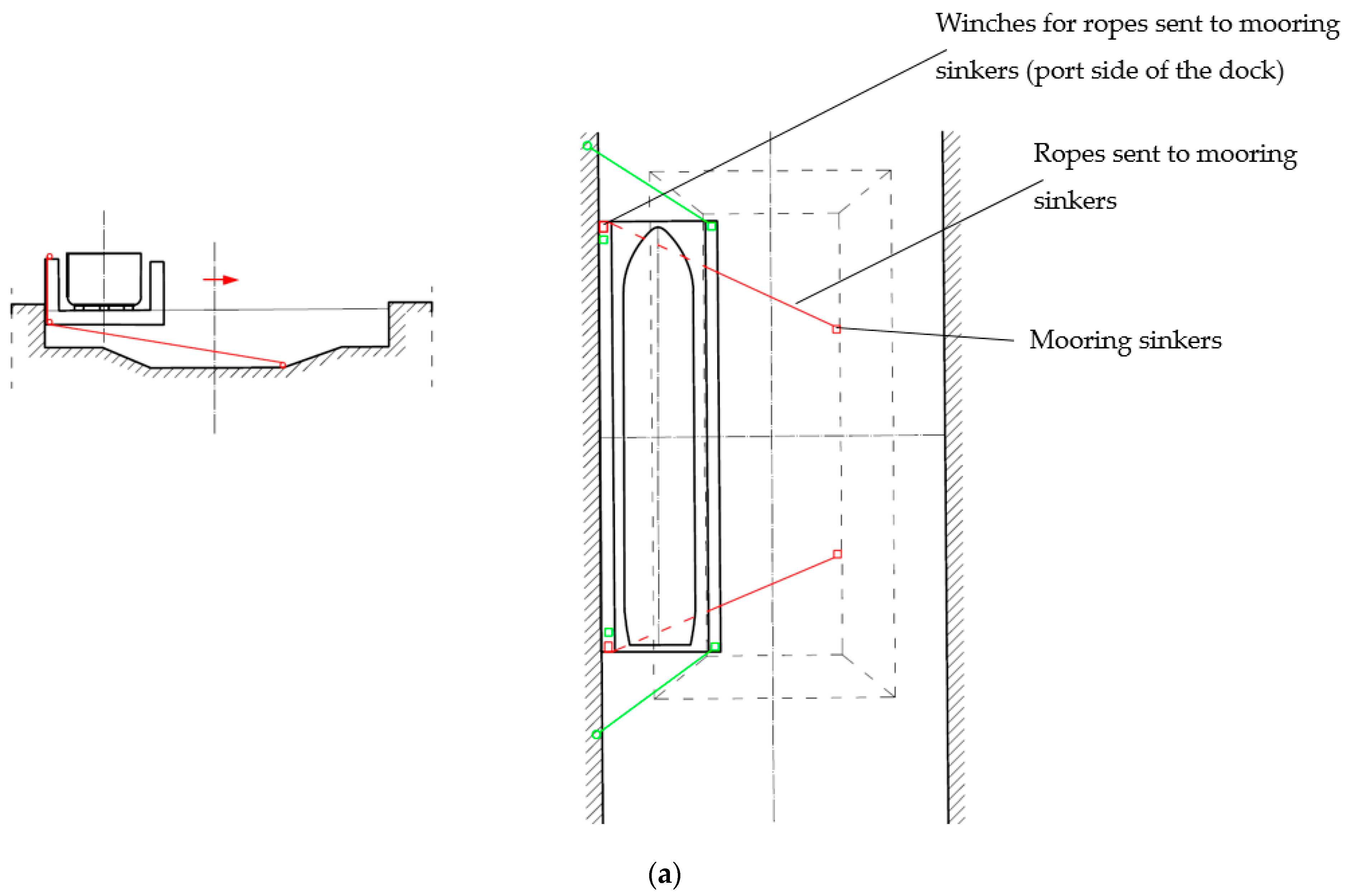
In order to avoid the need to moor the dock to the opposite quay, several variants of the rope winch-based system with mooring sinkers fitted at the bottom of the canal have been examined (
Figure 14). Although the solution facilitates the moving and stabilising of the dock in position, the entire system is even more difficult to maintain and expensive. Certain sections of ropes will remain under the water throughout the entire life cycle of the dock, and will therefore require frequent inspections and replacement of corroded ropes.
5.3. Hydraulically Driven Mechanical System
Since the systems described above do not meet all of the requirements and criteria listed in
Section 3, another system has been developed, in several variants. Based on a trussed structure, it can fold and unfold in the same way as a ladder, pushing the dock away from the quay or pulling it towards the quay.
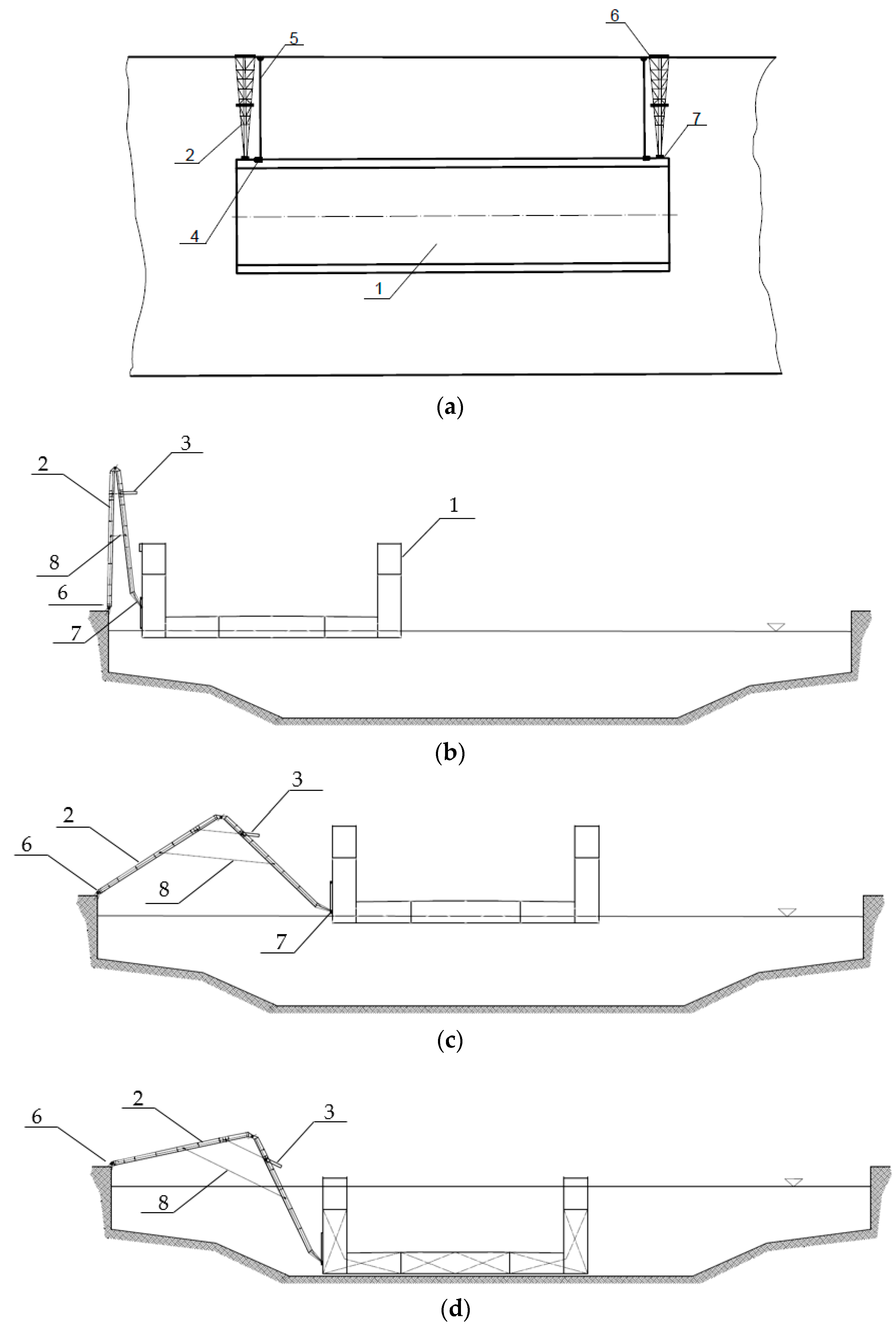
The best variant of the system is shown in
Figure 15. Double-acting, telescopic hydraulic cylinders are used to unfold the arms (trusses). As the weight of the truss arms has a considerable effect on the forces generated in the cylinders when pulling the dock to the quay, additional rope winches (located on the port side of the dock) are used to facilitate pulling the dock to the quay. The design of the arms, their connection to the quay and to the dock not only ensure adequate movement of the dock, but also stabilise the dock in position when the ship is docked.
The dock at the quay or moored off the quay is moved by means of truss arms extended by hydraulic cylinders. The parameters of the cylinders, their mounting coordinates in the arm structure, and the length of the arms are suited to move the dock away from the quay over a distance of 28 m. Once the dock has been moved, the hydraulic power of the cylinders is switched off and the arms maintain the position of the dock, stabilising it while the dock is being submerged and the ship pulled in. When the ship is brought in, the dock emerges, picks up the ship, and is pulled to the quay when the hydraulic power is activated. The arms are connected to the quay by means of an articulated connection, whilst the connection between the arms and the dock is articulated and sliding, to compensate for changes in the water level in the Parnicki Canal. Two rope winches installed on the dock support the hydraulic cylinders when pulling the dock to the quay in adverse weather.
6. Assessment of Systems for Moving and Stabilising the Dock in Position
The developed concepts, as described in
Section 5, have been assessed for meeting the requirements and design criteria (as specified in
Table 4). The results of the assessment are shown in
Table 11.
An analysis of the assessment outcome (see
Table 11) shows that while all of the developed systems meet most of the requirements and criteria (systems 5.1.a, 5.1.b, 5.2.a, 5.2.b), only system 5.3 meets all of them. Hence, further design work has been performed for a hydraulically driven mechanical system (
Section 5.3).
7. Technical and Operational Parameters of the Dock Moving System
Based on the requirements and criteria listed in
Table 4 and the maximum forces acting on the floating dock shown in
Table 9, a technical design of the hydraulically driven folding arms has been developed (
Figure 16) and the technical and operational parameters for the system have been calculated (
Table 12).
The pushing force of the cylinders is far greater than the force required to push the dock away from the quay. By reducing the pressure in the hydraulic system for extending the cylinders, this force has been reduced. The duration of a full cycle (pushing the dock away from the quay and pulling it towards the quay) is ca. 35 min.
8. Concept for an Environmentally Friendly Power Supply for the System for Moving and Stabilising the Dock in Position
The hydraulic system for moving the dock consists of four hydraulic cylinders, two sets of hydraulic power units, and a control console with setters to control the hydraulic cylinders. The total nominal output of the electrical equipment for the hydraulic system is ca. 23 kW. Due to the deliberate reduction of pressure in the hydraulic system for moving the dock away from the quay, the actual drive power is lower.
The hydraulic system is powered by photovoltaic panels with batteries, which store the electricity for use when moving the dock.
The expected number of ship dockings per year is 15. A full cycle of moving the dock away and towards the quay (and thus the electricity requirement) is ca. 35 min. On this basis, the capacity of the batteries to power the hydraulic system has been determined. During the periods between dockings (ca. 24 days on average), the batteries will be recharged. For the purpose of recharging the batteries, the necessary power of photovoltaic panels has been estimated for average sunshine conditions. In summer time, any excess electricity generated by the panels will be fed back into the electricity grid or used for maintenance work at the dock. In winter, any energy shortfall will be compensated for from the electricity grid.
A combination of panels and batteries has been selected for the average sunshine conditions in Szczecin. Thus, the solution is highly environmentally friendly, and the system’s power supply uses renewable energy sources.
The estimated parameters of the environmentally friendly power supply for the hydraulic system are shown in
Table 13.
9. Final Conclusions
Based on the literature review of the subject, it can be concluded that the designed system for moving and stabilising a floating dock in position is an innovative solution which makes it possible to dock a ship in the dock trench in the central part of the Parnicki Canal.
The designed PSPD system fulfils all of the requirements and criteria for moving and stabilising the dock in position during docking operations at the dock trench in maximum weather conditions corresponding to 5 °B.
One of the most important features of the system is the utilisation of renewable energy sources—electricity will be generated by photovoltaic panels and stored in batteries. The selected set of panels for the solution guarantees that the energy stored in the batteries will be sufficient for 1 h of operation of the dock moving system. The reserve of energy is ample, since one full cycle of moving the dock away from and towards the quay lasts ca. 35 min. It is therefore a system with zero greenhouse gas emissions and a zero carbon footprint.
This innovative PSPD system completely eliminates the need for using diesel-powered harbour tugboats to move the dock.
The construction of the floating dock was launched in May 2023 and completed in September 2023. In October 2023, the construction of the PSPD system was completed and the system was installed at the Repair Quay. The system will be tested and trial runs will be performed in November 2023. The PSPD system operators will be trained in the same month. It is expected that later this year, the first ship will be docked and repaired in this new eco-friendly floating dock.
The research project discussed in this paper and the subsequent construction of an eco-friendly system for moving and stabilising the dock in position at the Parnicki Canal can be considered highly innovative. The use of renewable energy sources to power the system makes it a truly green solution which contributes to the protection of the environment.


