Abstract
Vortex generators and pin fins are conventionally used to deliver fluid mixing and improved convective heat transfer. The increased pressure loss following a fractional increase in heat transfer, as well as the complex manufacturing design, leave room for improvement. The present work proposes a novel diverging–converging base corrugation model coupled with vortex generation using simple geometrical modifications across rectangular microchannels to ensure a superior performance. The Nusselt number, friction factor, and flow phenomenon were numerically studied across a Reynolds number range of 50–1000. The optimum cross-section of the microchannel-generating vortices was determined after thorough study, and base corrugation was further added to improve heat transfer. For the vortex–corrugation modeling, the heat transfer enhancement was verified in two optimized cases: (1) curved corrugated model, (2) interacting corrugated model. In the first case, an optimized curve generating Dean vortices was coupled with base corrugation. An overall increase in the Nusselt number of up to 32.69% and the thermal performance of “1.285 TPF” were observed at a high Reynolds number. The interacting channels with connecting bridges of varying width were found to generate vortices in the counter-flow configuration. The thermal performance of “1.25 TPF” was almost identical to the curved corrugated model; however, a major decrease in pressure, with a loss of 26.88%, was observed for this configuration.
1. Introduction
1.1. Background
A stable operating temperature is an essential requirement for most electronic equipment, as well as lab-on-chip devices. Recent advancements in technology have provided intense functionality in small-sized equipment. Owing to their small size, these micro-devices find use in varied applications, including aerospace, biomedical, chemical, computing, and automotive industries. However, the localized heat generation from these devices greatly threatens their durability and performance. This localized heat needs to be constantly removed for optimum operation and to avoid any damage to the underlying equipment. In this regard, microchannel heat exchangers have come forth as an attractive solution to dissipate heat from small spaces. Heat flux modeling can be used to predict the cooling load; however, variations in practical applications make its use difficult in problems where the flux cannot be predicted. The primary objective of heat sinks is to ensure equipment remains below a critical temperature; therefore, their performance needs to be studied when the maximum allowable temperatures have already been achieved. In extreme conditions, the energy efficiency and resulting convective heat transfer is significantly important. Therefore, they can be used to determine the maximum achievable heat dissipation for these devices.
1.2. Literature Review
The increasing number of transistors on electronic chips has significantly increased the heat generation rates of such equipment [1]. Moore’s law predicts an increase in the computing functionality of modern electronics, and hence a proportional increase in heat generation is expected [2,3]. Thermal management techniques also need to continue evolving to catch up with the cooling requirements [4]. Microchannel heat sinks [5], phase change cooling [6,7] and micro-jet cooling [8] are some of the proposed methods for delivering an improved thermal management to high-performance computing chips [9,10]. Microchannels are usually preferred for applications in confined spaces, where the hydraulic diameter is between 1 and 1000 microns [11]. Therefore, using microchannels to reduce the risk of thermal hotspots on microprocessors is a promising application for highly optimized heat sinks. Hydraulic diameter, cross-section, and wall effects were identified as the parameters affecting the design of these devices [11,12]. Geometrical variations like sinusoidal structures [13], converging–diverging manifolds [14], and pin fins [15] have been used in the literature to study the improved heat transfer effects. Most studies have attempted to improve the Nusselt numbers [16] of micro heat sinks by changing their hydraulic diameter and mixing effects at different Reynold numbers. The application of secondary cooling methods to enhance the overall heat transfer has not been thoroughly investigated, mainly because the secondary effects lead to insignificant heat transfer benefits compared to the large pressure drops across the flow region. Therefore, more studies are needed to properly investigate efficient methods of utilizing secondary flow effects. In such cases, experimental methods are expensive; therefore, Computational Fluid Dynamics (CFD) can be effectively utilized to accurately predict the fluid flow and heat transfer rates [17,18].
Different schemes of fluid mixing have been investigated in the literature. Passive fluid mixing can be obtained by subtle variations in geometry, surface roughness, curvature, or obstructions. Some scholars have concluded that surface corrugation is an effective way to enhance heat transfer [19,20]. Typically, there is a significant temperature gradient across the cross-section of coolants flowing within microchannels. The highest temperature occurs close to the heated walls, where the fluid is in contact with the solid surface, leading to conjugate heat transfer across the boundary. However, the heat relieved from the walls is not always uniformly transported across the entire fluid domain within the cross-section of the channel. Therefore, the present study identifies uniform temperature distribution within coolants as the key to delivering an improved thermal performance. To overcome this bottleneck, Wang et al. [21] proposed the use of porous fins to induce the mixing of fluid within the channels. Petal-shaped ribs were used by Q. Zhang et al. [22] to induce vortices and promote the mixing of high-temperature fluid close to the boundaries with the cooler fluid at the center of the channel. Sun [18] used numerical analysis to study the effects of semi-elliptical protrusion on the heat transfer and friction factor. Liu [23] studied the effects of using winglets to promote the mixing across the base of microchannels. However, the use of pins, winglets, and arrays complicates the manufacturing of such devices, in addition to increasing the pumping requirements encountered due to increased pressure losses [8,24]. Grooves [25], cavities [26], ribs [27,28], and vortex generators [25,29] can also be utilized for secondary flow generation [30]; however, they do not always reflect the desired heat transfer enhancement. Therefore, any effective design that utilizes secondary cooling techniques must be able to deliver a significant thermal advantage at a low pressure drop penalty to be considered an effective solution.
The simplicity of design is important from a practical perspective, especially when manufacturing limitations are present. While complex design structures can be produced through additive manufacturing [31,32], such methods are not always suitable for mass production [11]. The prevailing microfabrication capabilities [33] severely limit the mass production of such devices at a large scale, and hence their ability to be classified as a good design. Therefore, any proposed design should be simple enough to allow for ease of manufacturing.
Nanofluids are an effective alternative to the single-phase fluids commonly used in cooling applications [34]. Nanofluids are a form of particle suspensions formed to disrupt the boundary layer formation, which improves the heat transfer coefficient and hence the overall performance of the coolant [35]. Numerical studies with aluminum oxide [36], graphene oxide [37], titanium oxide [38,39], zinc oxide [40], and zirconia [41] nanoparticles were performed to establish the superiority of nanofluids over single phase cooling fluids [42]. Zeng et al. [36] numerically studied the effects of alumina nanofluid on novel grooved rectangular microchannels for the enhanced cooling effects of nanofluids across grooved channels. Li et al. [43] demonstrated the heat transfer enhancement achieved through nanofluids at the cost of increased pumping power. Therefore, the use of nanofluids as coolants provides benefits for heat transfer enhancement; however, we conclude that their affects can be further enhanced by utilizing them with the secondary flow disruption technique, which allows for improved heat transfer rates.
A review of the available literature suggests that the use of corrugation in microchannels is still emerging, and more studies are needed to achieve the best utilization of the hydrothermal characteristics of heat sinks. The curved microchannel geometries have been known to generate Dean vortices [44]; however, their use as a secondary passive mixing method in combination with the base corrugation has not been studied. Further, according to the authors’ knowledge, no study has been performed on interacting microchannels, which is proposed in the present work. Another objective of the study was to keep the overall design relatively simple from a manufacturing viewpoint, thereby facilitating experimental studies in the future. Therefore, the novelty of the present work lies in the following three aspects.
- The introduction of a novel, interacting microchannel model which generates rotating vortices.
- The generation of vortices across an optimized cross-section and the addition of a novel diverging–converging base corrugation model to promote passive fluid mixing combined with continuous flow disruption.
- The comparison of the results of a nanofluid model proposed by Rea et al. with the KKL model to determine the validity of Rea et al.’s model for geometries compared the one proposed under the study.
According to the authors’ knowledge, no such study has been performed to determine the thermo–hydrodynamic performance of a corrugated design combined with the vortex generation phenomenon. Therefore, the proposed work can provide a new way to harness passive mixing as an effective tool without a significant pressure drop across microchannels.
2. Materials and Methods
2.1. Methodology
Straight microchannels of fixed length, as shown in Figure 1, were studied, with varying aspect ratios achieved by changing the width and height parameters, as given in Table 1. The length of the channel was kept fixed at 18 mm, according to the length of the microchip, while the flow velocities were varied between a Reynolds number range of 100 to 1000, to study the effects of an increase in flow velocity upon a change in the aspect ratios. Figure 1 shows the model developed for conjugate heat transfer analysis, where the cooling fluid flows across a channel of fixed length. The solid domain was coupled to the fluid domain and a heated wall condition was applied to the base of the channel.
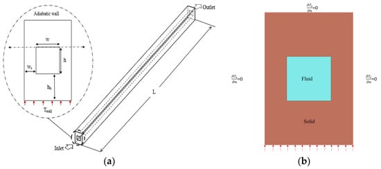
Figure 1.
(a) Schematic of straight channel, (b) section view of channel.

Table 1.
Straight channel analysis parameters.
Deionized water, having temperature-dependent fluid properties, was chosen as the coolant to determine the optimum cross-section for straight channels. The numerical results were evaluated in terms of the dimensionless Nusselt number and friction factor as the performance variables.
An optimization study for aspect ratios was performed to select the cross-section providing the highest cooling rates. However, this led to a high number of cases that needed to be studied, as given in Table 1; therefore, the design point was identified as the criterion to reduce the number of numerical simulations that were needed to be performed for the present study. The best design point for each aspect ratio was identified through the optimization of dimensionless parameters for both the pressure drop and convective heat transfer in terms of the friction factor and the Nusselt number, respectively. Using a statistical analysis software, Minitab 21, we identified an optimized point for each aspect ratio. The optimized point was defined as the point of intersection of the Nusselt number and the friction factor, as shown in Figure 2. This provided a reasonable tradeoff between the convective heat transfer and pressure drop. The corresponding Reynolds number was considered the design point of that aspect ratio. Through this optimization and data reduction technique, the total number of simulation cases adopted for this detailed study was reduced from 1470 to 147.
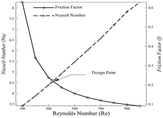
Figure 2.
Design point selection.
Subsequently, in order to harness the effects of vortex generation, a bend was introduced along the length of the microchannel, as shown in Figure 3. The effects of Dean vortices were studied by varying the bend angle between 0 to 90 degrees at incremental intervals given in Table 2. Optimization of the bend angle was performed to find the bend allowing for highest convective transfer rates at the lowest pressure drop penalty. This was achieved using a design point selection based on the same criterion as discussed previously for selection of the optimum cross-section of a straight channel.
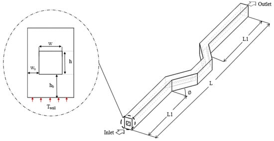
Figure 3.
Bended channel geometry.
Table 2.
Bent channel parameters.
The dual channels with a connecting bridge, as shown in Figure 4, were used in both the parallel and the counter flow configurations. The flow phenomenon for both configurations in the interacting channel geometry was observed. The resulting cooling effects and pressure drop across the interacting channels were studied for both flow orientations under the parameters given in Table 3.
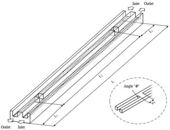
Figure 4.
Interacting corrugated channel (counterflow).
Table 3.
Interacting channel design parameters.
The continuous flow disruption at the base of the microchannel was achieved by adding a diverging–converging base corrugation, as shown in Figure 5. The flow disruption across the entire cross-section of the base delayed the onset of boundary layer formation and hence provided the possibility for higher convective heat transfer rates. This is mainly due to the presence of a heated wall only at the bottom of the entire domain. Therefore, we theorized the overall conjugate heat transfer could be improved by utilizing the effects of corrugation at the base wall. This effect can be further enhanced through effective heat conduction across the entire fluid cross-section in the upper regions of the channel by flow mixing. This mixing was achieved through the utilization of vortices that provided effective fluid mixing across the remaining flow region. This technique was able to provide a stronger mixing of heating effects across the entire cross-section of fluid in the microchannel. The corrugation model was studied for the best aspect ratio along the length to determine the best geometry as well as variation in the depth of the corrugation model to determine if it had any significant effects on the cooling rates.
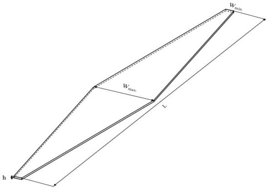
Figure 5.
Diverging–converging corrugation geometry.
The diverging–converging corrugation model proposed in Figure 5 was added to the base of the channel for both curved and interacting channels. The heat transfer rates, and the flow phenomenon were observed, and the results are presented in this paper.
The cases were studied to determine the combined effect of vortex generation with base corrugation. This combination of passing mixing and flow disruption close to the base of the microchannel had a better thermal performance compared to the regular straight channels. Once the best-performing geometries were optimized for both cases, alumina nanofluids were added to the deionized water to study the effects of changing the operating fluid on the heat transfer rates. The results of the experimentally determined relations by Rea et al. [45] were compared with the reliable KKL model to determine the validity of these relations and for comparison of the results.
2.2. Assumptions
The numerical model developed for this heat transfer problem was assumed to satisfy the following criteria.
- Fluid incompressibility in a three-dimensional domain.
- Steady-state heat transfer.
- Negligible radiation heat transfer and viscous heating.
- No slip conditions at the wall.
- No effect of channel surface roughness.
- No effects of natural convection.
2.3. Governing Equations
Based on the above-mentioned assumptions, the governing equation for the case can be expressed as
where is the velocity vector given as ,
2.4. Numerical Methods
The Reynolds number for this study was varied between a range of 100 to 1000, as similar numbers have already been utilized in previous studies [27]. The fluid–solid interface was specified as a coupled boundary, with the solid wall having fixed properties. The numerical model developed for this conjugate heat transfer problem was assumed to have the following characteristics.
- Inlet: Tin = 298.15 K and w = win, u = 0, v = 0.
- Outlet: p = 1 atm.
- Solid Liquid Interface: Ts = , ; u = 0, v = 0, w = 0.
- Bottom wall: Dirichlet boundary condition, T boundary [16].
- Other wall surfaces: .
The principal fluid flow was along the direction of the z-axis, as given above. The walls were set to no-slip boundary, making the velocity components along the other two axes zero. The velocity inlet at a fixed temperature is a function of hydraulic diameter, which, in turn, is based upon the Reynolds number. The top wall is the same thickness as the base, while the sides are given as half the thickness of the bottom wall to replicate practical scenarios, where the sides are also occupied by neighboring channels. The outlet was fixed as a pressure boundary to mimic the effects in an experimental setup.
The ANSYS workbench meshing module was utilized for generating a hexahedral non-uniform mesh, as shown in Figure 6. Inflation was applied to keep the sizes of the mesh elements close to the walls smaller, to accurately capture the boundary layer effects.
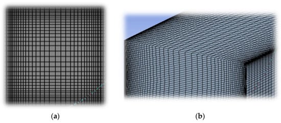
Figure 6.
(a) Channel cross-section, (b) bend (top view).
The numerical solutions of governing equations for the conjugate heat transfer problem were achieved through commercial Ansys Workbench 2021, Fluent module. The properties of deionized water, as given in Table 4, were defined in terms of the temperature as a variable. The numerical scheme used for this study is given in Table 5. A convergence criterion of “1 × 10⁻⁶” was set, considering the solution accuracy and convergence time. The study was performed using two Intel Xeon X5660 processors (Intel, Santa Clara, CA, USA) with, overall, 12 cores and 64 gigabytes of ram. The hexahedral mesh elements were used to generate a structured non-uniform mesh, as shown in Figure 6. Double precision simulations were performed, with the number of mesh elements for an average case being 4.32 million and 6.5 million elements for single and interacting dual channel models, respectively.
Table 4.
Properties of DI water, copper, and alumina.
Table 5.
Numerical scheme.
2.5. Parametric Relations
Shah and London [16] proposed the analytical relation for the fanning friction factor across rectangular ducts in terms of the Poiseuille number. The number itself is a function of the aspect ratio of the channel, and the analytical relation for both fully developed and developing flow solutions were validated for the present study.
Blevins [47] proposed the Darcy friction factor relation for rectangular channels as a ratio of the Reynolds number, width, and height of the channel. The analytical relation of the friction factor proposed recently by Bejan [48] uses similar parameters as the ones proposed by Blevins [47]. Validation against one analytical equation is usually enough; however, the present work was validated against all the analytical relations to establish a thorough study about the analytical relations. It was found that all the analytical relations provide very similar results for such applications and can be used interchangeably. The generalized Nusselt number relation [49] from the literature was used for the present study. The nanofluid density can be characterized as a physical mixture of fluid and nanoparticles. The specific heat capacity nanofluid is expressed in the form of a thermal equilibrium equation between base fluid and nanoparticles.
The viscosity and thermal conductivity of the alumina nanofluids were experimentally determined and separate relations have been proposed by Rea et al. [45]’s and the KKL [50] model. The model proposed by Rea et al. is independent of geometrical variations, while the KKL model was based on experimental datasets of volume fractions up to 4%. The effective thermal conductivity is a sum of static conductivity and the Brownian motion of particles.
Evaluation of the design was based on the established relations available in the literature. The Nusselt number and friction factor efficiency of microchannels can be expressed as a ratio of novel design and a conventional straight channel [51]. The overall thermal performance of the design can be evaluated, as described by Harikrishnan [52].
3. Results and Discussion
3.1. Grid Independence
The grid independence was performed for different mesh sizes to achieve the stabilization of the mesh size and ensure the reliability of the results. The mesh was varied from coarse to very fine with an increasing number of elements until a stable solution with an acceptable numerical error percentage was achieved. Thus, grid independence was achieved at a condition where large changes in the mesh density led to negligible changes in the numerical results. A Reynolds number of 500 was chosen as a mean reference parameter over the range of 0 to 1000. The numerical values of the friction factor achieved against varying mesh densities were validated against the established analytical relations in the literature. The results, plotted in Figure 7, were found to be in good agreement with the analytical results, as shown by an error of 4% occurring due to the initial developing flow region across the microchannel, as shown in Table 6.
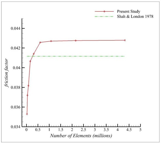
Figure 7.
Grid independence [16].
Table 6.
Grid Independence.
3.2. Validation
As discussed in the previous section, the results of the numerical study were compared to the analytical relations available in the literature. The analytical relations given for both the fully developed and developing flow, Nusselt number, and friction factor [16] have been discussed in the previous section. However, for the present case, the flow profile is still developing as it enters the channel flow domain; therefore, it is a combination of developing and fully developed flow regimes. Therefore, the results needed to be plotted against both analytical relations proposed by Shah and London [16]. While validation with analytical relations is very reliable [18], for the sake of completeness, the present study was also validated against the results of the analytical relations of the friction factor proposed by Blevins [47] and Bejan [48]. It was found that the relations provide similar results, especially in the case of higher Reynolds numbers.
The results in Figure 8a confirm that, for small aspect ratios, the numerical model displays good agreement with the analytical results for a purely rectangular channel cross-section. An error of less than 6% with the analytical relations was achieved for the numerical solution, which is a consequence of the pressure drop in the flow development region [52] at the entrance of the channel. The results provided exceedingly good agreements at higher Reynolds numbers. However, the analytical relation proposed by Bejan [48] only shows a good correlation beyond a Reynolds number of 400, and underpredicts the solution at low Reynold numbers below 300. For the high aspect ratio, shown in Figure 8b, where the cross-section becomes a perfect square, it was shown that the numerical results provide a better agreement with the developing flow correlations and those with a higher Reynolds number. The flow across the entire square cross-section remains developing throughout the region and therefore provides improved heat transfer rates.
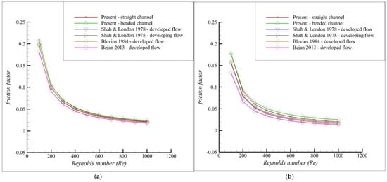
Figure 8.
Friction factor validation for Shah and London [16], Blevins [47], and Bejan [48]. (a) Aspect ratio 0.167. (b) Aspect ratio 1.
3.3. Results
The optimized design points for each geometry were plotted against the aspect ratios. Straight channels of varying aspect ratios were modeled using the thermophysical properties of the deionized water. The parameters of width and height were varied against a fixed channel length of 18 mm, which was fixed according to a square microchip design for which the solution is being proposed. The optimized design points for each geometry were finalized using the friction factor and Nusselt number parameters. The optimization was based on a design point criterion, where the performance of the optimum points for each geometry were compared. The selection criterion was based on the sensitivity of the parameters and a difference in the absolute value of less than was achieved for the Nusselt number. Multiple aspect ratios were investigated against each geometry to find the most efficient design providing the highest convective heat transfer characteristics. The Nusselt number and non-dimensional pressure drop results obtained for the different aspect ratios are given in Figure 9a and 9b, respectively.
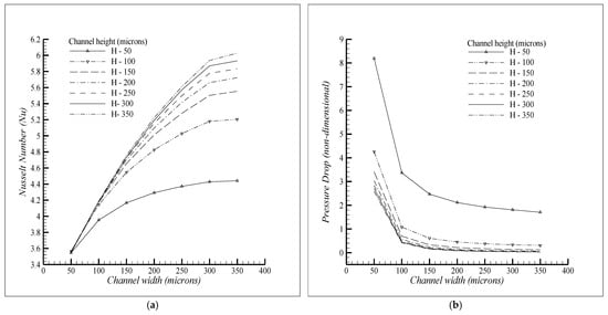
Figure 9.
Aspect ratio effects. (a) Nusselt number. (b) (Non-dimensional) pressure drop.
The microchannel with an aspect ratio of 1 and a side length of 300 microns provided the best performance and the highest possible Nusselt number within the tolerance range defined previously. The selection was based on the criterion that an increase in the width beyond this side length provided a negligible increase in the Nusselt number at no change in the friction factor. Further, it was shown, through the literature review, that for the cooling of the surface, it is preferable to have a higher number of channels. Therefore, going beyond this limit might negatively affect the multichannel performance, as increasing the channel width no longer provides the intimate contact of the fluid with the surface.
Upon the finalization of the optimum aspect ratio of the channels, two bends of varying angles between a range of 0–90 degrees were studied. A total of six cases, given in Table 7, were initiated with periodic increments of 15 degrees to obtain the Nusselt number and friction factor against each bend angle. The multi-objective response optimization of the bent channel was carried out, using angle “” as a continuous variable, while the dimensionless pressure drop and Nusselt number were chosen as the response variables. The optimized angle with acceptable composite desirability was finalized as the optimum bend angle, as shown in Figure 10.
Table 7.
Bent channel cases.
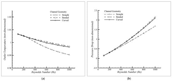
Figure 10.
Comparison between (a) dimensionless temperature, (b) dimensionless pressure drop.
The optimized angle of 35° (approx.) was finalized as the optimum bend angle based on the design criterion. The resulting data from the bent channel was used to obtain a regression model for the Nusselt number and pressure drop in terms of continuous variable “” at the Reynolds number for the design point. The accuracy of this regression models is more than 95% and the characteristic equations for bent channels with deionized water having temperature-dependent properties can be expressed as
The flow phenomenon across this bent channel was compared against an equivalent curved channel, obtained through the smoothing of the sharp edges of the bend, to determine the difference between the heat transfer rates for both geometries. The corners of the bends were replaced by an equivalent curve which provided equivalent Nusselt number and friction factor values. The data shown in Figure 10a,b present the dimensionless outlet temperature and pressure drop, respectively, where a negligible difference in both values were observed for the bent and curved channels.
Therefore, we conclude that the previously determined equations are also applicable for the curved channels, where the dimensionless outlet temperature and pressure drop are approximately the same for both cases, as shown in Figure 10. The cross-section of the flow phenomenon at Reynolds number 500 and 1000 for both the straight and curved channels is shown in Figure 11. The flow leads to the generation of Dean vortices along the curve and the noticeable increase in the convective heat transfer and dimensionless pressure drop beyond a Reynolds number of 300 is linked to this phenomenon. The corresponding phenomenon can be seen across the cross-section of the curve, as shown in Figure 12.
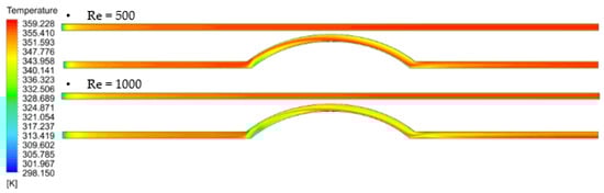
Figure 11.
Curved channel flow.
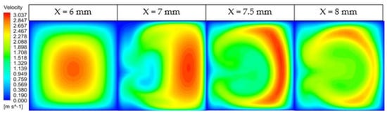
Figure 12.
Dean vortices across the curve.
The curved channel displays fluid mixing due to the generation of Dean vortices across the curved region of flow. However, a complete vortex along the cross-section of the channel leads to a higher pressure drop due to its contact with a solid boundary at the bottom surface. The convective heat transfer rates can be further increased through continued flow disruption across the base of the fluid. For this purpose, a corrugation pattern applied to the base of the fmicrochannel was proposed based on a periodic diverging–converging corrugation model. The width ratio and depth of this corrugation were studied using separate design parameters. The design parameters were identified as the width ratio and aspect ratio, and they were defined as and . The increase in the depth of the channel shows improved heat transfer rates and a lower pressure drop trend as compared to the same corrugation pattern with a smaller height, as shown in Figure 13a,b.
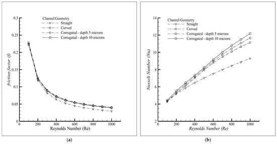
Figure 13.
Aspect ratio variation. (a) Friction factor, (b) Nusselt number.
The flow phenomenon at a Reynolds number of 500 across the corrugated model is shown in Figure 14, where the temperature can be observed to be rising across from the cross-section of the corrugated channel model. This is in complete contrast to the straight channel model, where the temperature distribution across the base of the channel was not uniform. The left image shows that, at various points across the corrugated channel length, after the fluid has crossed the first diverging–converging corrugation model, the heat is already starting to travel further across the cross-section as compared to the straight channel, and once at the end, we can observe a clear increase in the temperature across the cross-section of the channel. Therefore, continuous flow disruption at the base of the channel is extremely efficient at dissipating heat across the fluid domain.
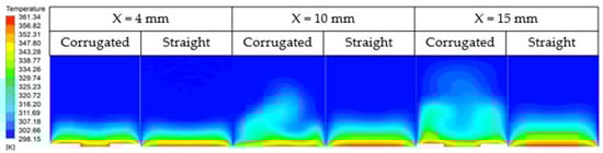
Figure 14.
Temperature variation across the corrugated base and flat base channels.
The comparison shown in Figure 15 shows that a decreasing width ratio shows an improved Nusselt number and friction factor. The decreasing width ratio shows the difference in the maximum and minimum width values of this model. Therefore, we conclude the difference between the maximum and minimum width dimensions should be maximum to achieve the best results.
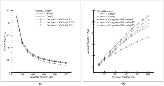
Figure 15.
Width ratio. (a) Friction factor, (b) Nusselt number.
The corrugation height of 10 microns was chosen as the reference height for the comparison of the different width ratios in terms of the efficiency of the channel. The overall thermal performance factor given in Figure 16 shows the improved efficiency of the curved corrugated channels over the curved and conventional straight channel geometries.
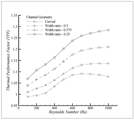
Figure 16.
Thermal performance factor.
An interesting phenomenon happens at a Reynolds number above 700 in the curved channels, where a further increase in the Reynolds number leads to a minor increase in the Nusselt number at a much larger increase in the friction factor. This leads to a decrease in the Thermal Performance Factor for curved factors above a Reynolds number of 500.
Upon establishing the benefits of using corrugated channels with vortex generation, A connecting bridge of varying width was introduced between two parallel channels to induce flow mixing and increase convective heat transfer. The orientation of the connecting bridge was varied from the previously determined optimum angle of 35° to 90° to determine the effect of changing the bridge angle on the fluid mixing and performance parameters. Both the curved and straight channels without corrugation were used as the reference geometries. The flow phenomenon was varied from the parallel flow type to the counter flow type for a comprehensive study. The simulation matrix is given in Table 8.
Table 8.
Interacting channel simulation matrix.
The cases mentioned in Table 8 were studied, and it was found that no convective heat transfer benefit was observed for the curved channel as well as the straight channel with a connecting bend at 35 degrees. However, an interesting phenomenon was observed for the interacting channels with a connecting bridge at 90 degrees, where vortices were observed to have been generated for counter flow phenomenon. The temperature profile at the base has been given in Figure 17 where enhanced cooling effects can be observed during the counter flow configuration, which is due to the fluid crossing over from one channel into the next through the connecting bridge.
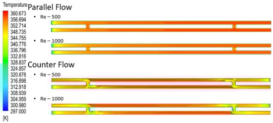
Figure 17.
Interacting channel flow behavior.
The parallel flow case resulted in the formation of a recirculation zone at the connecting bridge, as shown in Figure 18. Apart from the minor increase in the surface area due to the connecting bridge, no significant cooling effects were observed. However, in the case of the counter flow configuration, the fluid crossed over into the neighboring channel, which resulted in the flow encountering the oncoming fluid of that channel. This caused separation at the fluid center and led to the development of counter rotating vortices, which provide significant heat transfer and less pressure drop benefits.
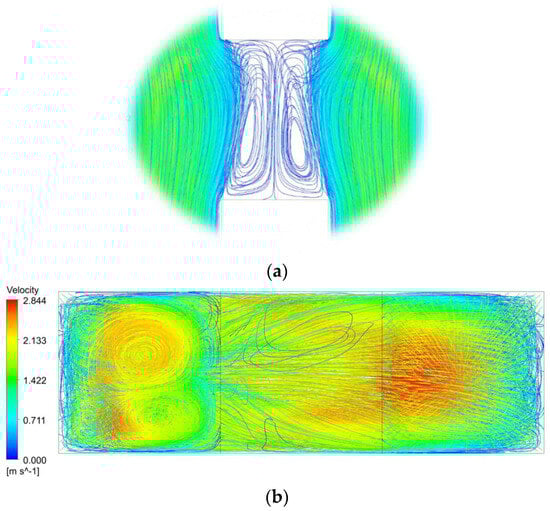
Figure 18.
Interacting channel. (a) Parallel flow, (b) counter flow.
The flow phenomenon was accurately captured in Figure 19 for both the parallel flow and counter flow configuration with the varying bridge width. However, it was found that the flow phenomenon predominantly remained the same in all cases, and therefore has no effect on the heat transfer rates across the interacting channels. Therefore, the interacting channel model can be thought to be independent of the bridge width.
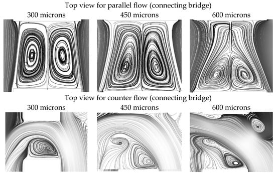
Figure 19.
Flow phenomenon at the bridge.
The cooling effect provided by the counter flow configuration was significantly more as compared to the results of the parallel flow configuration. The decrease in the outlet temperature can be explained by the fact that, as the fluid moves closer to the outlet of the channel, the oncoming cooler fluid mixes, causing the localized Nusselt number to be higher than the overall value. Therefore, a quantitative analysis needed to be performed to determine the overall effects on the performance of the microchannels.
A major decrease in the pressure drop was observed for the counter flow configuration across the microchannels. The friction factor efficiency for the parallel flow was consistently below one, leading to a lower overall thermal performance factor. However, the decrease in the pressure drop and increase in the Nusselt number provided an overall increase in the thermal performance of 1.25 for the counter flow channels, as shown in Figure 20.
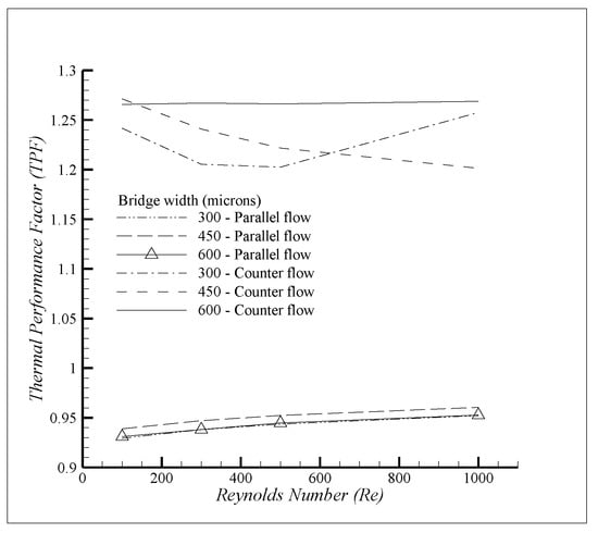
Figure 20.
Thermal performance factor of interacting channel.
Base corrugation was added to the counter flow channels to study the combined effect of vortex generation and base corrugation for this type of channel. As shown in Figure 21, it was found that base corrugation increases the Nusselt number appreciably at no significant change in the pressure drop. Therefore, this model has superior benefits for all cases.
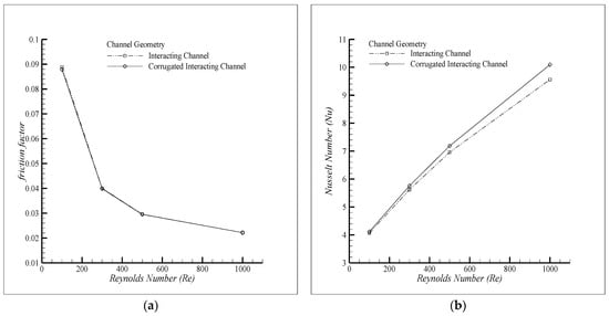
Figure 21.
Corrugated interacting channel. (a) Friction factor, (b) Nusselt number.
The finalized model for this case was then further studied in two separate nanofluid models: one developed by Rea et al., and the KKL model. The model proposed by Rea et al. was developed for circular microchannels; however, the final relations developed for this model were independent of any geometric constraint. This model was tested against the reliable KKL model to determine if the values are applicable for different geometries. Based on the results obtained in Figure 22, we conclude that the friction factor shows good agreement; however, the Nusselt number was underpredicted by 4% in comparison to the KKL model.
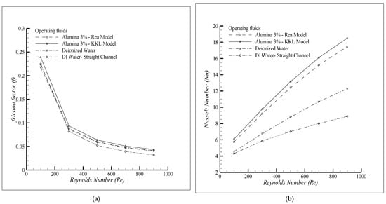
Figure 22.
Nanofluid comparison. (a) Friction factor, (b) Nusselt number.
4. Conclusions
The present study focuses on the numerical three-dimensional analysis of the conjugate heat transfer and hydrodynamic flow behavior of rectangular microchannels. A combination of base corrugation and rotating vortices were utilized to delay the onset of boundary layer formation. The results obtained under the steady state assumption were in good agreement with the experimental and analytical relations, leading to the major findings of this study. The increase in the aspect ratio for the microchannels provides an increase in the Nusselt number; however, this incremental increase diminishes at higher aspect ratios. Also, with a greater channel width, the increase in height leads to a smaller increase in the magnitude of the Nusselt number. It was found that the vortex generation phenomenon can occur in geometries other than curved channels either due to geometric variation or a change in the flow characteristics, as exemplified by the occurrence of the counter-rotating vortices in the bent channels of up to 90° as well as the channels with a connecting bridge under the counter flow configuration. For both the bent and curved channels, Dean vortices were generated; however, for the curved channels, the vortices were generated at Reynolds numbers beyond 300; therefore, we conclude that a minimum threshold velocity is needed for the development of Dean instability. The vortices were observed for all Reynolds numbers in the interacting channels under the counter flow configuration. The generation of vortices provides homogeneity and improved heat transfer rates. The resulting passive mixing improved the heat transfer rates by 20% due to Dean vortices and a further increase of 4% was observed due to the addition of base corrugation. The heat transfer rates for the corrugation model are dependent upon the width ratio and aspect ratio parameters, while being independent of the amplitude ratio. We conclude that both models deliver similar TPF values; however, the performance parameters reveal drastic differences in the friction factor and Nusselt number. A closer look at the parameters for the bent channels reveals that the increase in the pressure drop lags behind the increase in the Nusselt number, while, for the interacting channels, a significant decrease in the pressure drop against an increase in the Nusselt number was observed. Therefore, the bent channels with base corrugation are more suited to applications where pumping power is not the limiting factor and increased heat transfer is desirable, while the interacting channels can be used in cases where a decrease in the pressure drop is critical in comparison to a limited increase in the Nusselt number. The nanofluid relations developed by Rea et al. underpredict the Nusselt number by 4% in comparison to the KKL model. Therefore, we conclude that the results presented by Rea et al. are geometry-dependent and not valid for general applications. This study can be further enhanced by including an experimental study and using a multichannel approach, in the future.
Author Contributions
Conceptualization, A.A.N. and E.U.; Methodology, A.A.N., E.U. and M.Z.U.K.; Software, A.A.N. and M.Z.U.K.; Validation, A.A.N.; Investigation, A.A.N.; Writing—original draft, A.A.N.; Supervision, E.U. All authors have read and agreed to the published version of the manuscript.
Funding
This research received no external funding.
Data Availability Statement
Data are contained within the article.
Conflicts of Interest
The authors declare no conflict of interest.
Abbreviations
| Re | Reynolds number |
| Nu | Nusselt number |
| T | Temperature |
| FVM | Finite Volume Method |
| microns | Micrometer |
| Cp | Specific heat (J/kg.k) |
| k | Thermal conductivity (W/m.k) |
| ff | Friction factor |
| K | Kelvin |
| Subscript | |
| s | Solid |
| f | Fluid |
| np | Nanoparticle |
| nf | Nanofluid |
| bf | Base fluid |
| al | Aluminum |
| Greek Symbols | |
| ρ | Density (kg/m3) |
| φ | Volume fraction |
References
- Yan, Y.; Xue, Z.; Xu, F.; Li, L.; Shen, K.; Li, J.; Yang, Z.; He, Z. Numerical investigation on thermal-hydraulic characteristics of the micro heat sink with gradient distribution pin fin arrays and narrow slots. Appl. Therm. Eng. 2022, 202, 117836. [Google Scholar] [CrossRef]
- Duan, Z.; Xie, G.; Yu, B.; Jin, P. Multi-objective topology optimization and thermal performance of liquid-cooled microchannel heat sinks with pin fins. Case Stud. Therm. Eng. 2023, 49, 103178. [Google Scholar] [CrossRef]
- Xiang, X.; Yang, J.; Fan, A.; Liu, W. A comparison between cooling performances of water-based and gallium-based micro-channel heat sinks with the same dimensions. Appl. Therm. Eng. 2018, 137, 1–10. [Google Scholar] [CrossRef]
- Khalaj, A.H.; Halgamuge, S.K. A Review on efficient thermal management of air- and liquid-cooled data centers: From chip to the cooling system. Appl. Energy 2017, 205, 1165–1188. [Google Scholar] [CrossRef]
- Liang, G.; Mudawar, I. Review of single-phase and two-phase nanofluid heat transfer in macro-channels and micro-channels. Int. J. Heat Mass Transf. 2019, 136, 324–354. [Google Scholar] [CrossRef]
- Emam, M.; Ahmed, M. Cooling concentrator photovoltaic systems using various configurations of phase-change material heat sinks. Energy Convers. Manag. 2018, 158, 298–314. [Google Scholar] [CrossRef]
- Avci, M.; Yazici, M.Y. An experimental study on effect of inclination angle on the performance of a PCM-based flat-type heat sink. Appl. Therm. Eng. 2018, 131, 806–814. [Google Scholar] [CrossRef]
- Xue, Z.; Yan, Y.; Shen, K.; He, Z.; You, J.; Zhang, C. Thermal performance enhancement of a micro-jet heat sink via parametric investigated micro pin fin arrays. Int. J. Therm. Sci. 2024, 196, 108717. [Google Scholar] [CrossRef]
- Kalkan, O. Multi-objective optimization of a liquid metal cooled heat sink for electronic cooling applications. Int. J. Therm. Sci. 2023, 190, 108325. [Google Scholar] [CrossRef]
- Kumar, S.; Singh, P.K. Effects of flow inlet angle on flow maldistribution and thermal performance of water cooled mini-channel heat sink. Int. J. Therm. Sci. 2019, 138, 504–511. [Google Scholar] [CrossRef]
- Li, J.; Yang, L. Recent Development of Heat Sink and Related Design Methods. Energies 2023, 16, 7133. [Google Scholar] [CrossRef]
- Zhang, J.; Zhang, B.; Lei, L.; Cheng, C.; Xu, J.; Zhou, N. Experimental Study on Heat Transfer Characteristics of Two-Phase Flow in Square and Rectangular Channels. Energies 2022, 15, 8453. [Google Scholar] [CrossRef]
- Khan, M.Z.U.; Younis, M.Y.; Akram, N.; Akbar, B.; Rajput, U.A.; Bhutta, R.A.; Uddin, E.; Jamil, M.A.; Márquez, F.P.G.; Bin Zahid, F. Investigation of heat transfer in wavy and dual wavy micro-channel heat sink using alumina nanoparticles. Case Stud. Therm. Eng. 2021, 28, 101515. [Google Scholar] [CrossRef]
- Tang, K.; Lin, G.; Guo, Y.; Huang, J.; Zhang, H.; Miao, J. Simulation and optimization of thermal performance in diverging/converging manifold microchannel heat sink. Int. J. Heat Mass Transf. 2023, 200, 123495. [Google Scholar] [CrossRef]
- Nunes, J.M.; de Oliveira, J.D.; Copetti, J.B.; Gajghate, S.S.; Banerjee, U.; Mitra, S.K.; Cardoso, E.M. Thermal Performance Analysis of Micro Pin Fin Heat Sinks under Different Flow Conditions. Energies 2023, 16, 3175. [Google Scholar] [CrossRef]
- Shah, R.K.; London, A.L. Chapter VII—Rectangular Ducts. In Laminar Flow Forced Convection in Ducts, 1st ed.; Shah, R.K., London, A.L., Eds.; Academic Press: New York, NY, USA, 1978; pp. 196–222. [Google Scholar]
- Sahar, A.M.; Özdemir, M.R.; Fayyadh, E.M.; Wissink, J.; Mahmoud, M.M.; Karayiannis, T.G. Single phase flow pressure drop and heat transfer in rectangular metallic microchannels. Appl. Therm. Eng. 2016, 93, 1324–1336. [Google Scholar] [CrossRef]
- Sun, H.; Fu, H.; Yan, L.; Ma, H.; Luan, Y.; Magagnato, F. Numerical Investigation of Flow and Heat Transfer in Rectangular Microchannels with and without Semi-Elliptical Protrusions. Energies 2022, 15, 4927. [Google Scholar] [CrossRef]
- Wan, Z.; Lin, Q.; Wang, X.; Tang, Y. Flow characteristics and heat transfer performance of half-corrugated microchannels. Appl. Therm. Eng. 2017, 123, 1140–1151. [Google Scholar] [CrossRef]
- Wan, Z.; Wang, Y.; Wang, X.; Tang, Y. Flow boiling characteristics in microchannels with half-corrugated bottom plates. Int. J. Heat Mass Transf. 2018, 116, 557–568. [Google Scholar] [CrossRef]
- Wang, S.-L.; An, D.; Yang, Y.-R.; Zheng, S.-F.; Wang, X.-D.; Lee, D.-J. Heat transfer and flow characteristics in symmetric and parallel wavy microchannel heat sinks with porous ribs. Int. J. Therm. Sci. 2023, 185, 108080. [Google Scholar] [CrossRef]
- Zhang, Q.; Wang, T.; Hou, Q.; Song, K.; Hu, W.; Wu, X. Thermal hydraulic performance augmentation by petal-shaped ribs in a two-pass cooling channel. Case Stud. Therm. Eng. 2022, 40, 102542. [Google Scholar] [CrossRef]
- Liu, H.-L.; Fan, C.-C.; He, Y.-L.; Nobes, D.S. Heat transfer and flow characteristics in a rectangular channel with combined delta winglet inserts. Int. J. Heat Mass Transf. 2019, 134, 149–165. [Google Scholar] [CrossRef]
- Yan, Y.; Wang, D.; Xu, F.; He, Z.; Yang, Z. Numerical study on hot spots thermal management in low pressure gradient distribution narrow microchannel embedded with pin fins. Int. J. Heat Mass Transf. 2022, 186, 122518. [Google Scholar] [CrossRef]
- Al-Asadi, M.T.; Mohammed, H.A.; Wilson, M.C.T. Heat Transfer Characteristics of Conventional Fluids and Nanofluids in Micro-Channels with Vortex Generators: A Review. Energies 2022, 15, 1245. [Google Scholar] [CrossRef]
- Ahmad, F.; Cheema, T.A.; Rehman, M.M.U.; Ilyas, M.; Park, C.W. Thermodynamic Analysis of Microchannel Heat Sink With Cylindrical Ribs and Cavities. J. Heat Transf. 2020, 142, 092503. [Google Scholar] [CrossRef]
- Ali, S.; Ahmad, F.; Akhtar, K.; Habib, N.; Aamir, M.; Giasin, K.; Vafadar, A.; Pimenov, D.Y. Numerical investigation of microchannel heat sink with trefoil shape ribs. Energies 2021, 14, 6764. [Google Scholar] [CrossRef]
- Wang, L.; Wang, S.; Liu, W.; Wen, F.; Zhou, X.; Wang, Z. Numerical predictions on heat transfer and flow characteristics in a straight channel with different geometric parameters wavy ribs. Appl. Therm. Eng. 2018, 140, 245–265. [Google Scholar] [CrossRef]
- Ebrahimi, A.; Rikhtegar, F.; Sabaghan, A.; Roohi, E. Heat transfer and entropy generation in a microchannel with longitudinal vortex generators using nanofluids. Energy 2016, 101, 190–201. [Google Scholar] [CrossRef]
- Memon, S.A.; Cheema, T.A.; Kim, G.M.; Park, C.W. Hydrothermal investigation of a microchannel heat sink using secondary flows in trapezoidal and parallel orientations. Energies 2020, 13, 5616. [Google Scholar] [CrossRef]
- Tiwari, R.; Andhare, R.S.; Shooshtari, A.; Ohadi, M. Development of an additive manufacturing-enabled compact manifold microchannel heat exchanger. Appl. Therm. Eng. 2019, 147, 781–788. [Google Scholar] [CrossRef]
- Tang, W.; Liu, H.; Zhu, L.; Shi, J.; Li, Z.; Xiang, N.; Yang, J. Fabrication of different microchannels by adjusting the extrusion parameters for sacrificial molds. Micromachines 2019, 10, 544. [Google Scholar] [CrossRef] [PubMed]
- Ashman, S.; Kandlikar, S.G. A review of manufacturing processes for microchannel heat exchanger fabrication. In Proceedings of the ASME 4th International Conference on Nanochannels, Microchannels, and Minichannels, Limerick, Ireland, 19–21 June 2006; pp. 855–860. [Google Scholar]
- Shang, X.-S.; Li, Q.-W.; Cao, Q.; Li, Z.-R.; Shao, W.; Cui, Z. Mathematical modeling and multi-objective optimization on the rectangular micro-channel heat sink. Int. J. Therm. Sci. 2023, 184, 107926. [Google Scholar] [CrossRef]
- Azodinia, M.; Mudabbir, M.; Karimipour, A. Numerical investigation of two-phase Al2O3 nanofluid in a microchannel equipped with bump through slip flow. Eng. Anal. Bound. Elem. 2023, 155, 1028–1034. [Google Scholar] [CrossRef]
- Zeng, X.; Yu, H.; He, T.; Mao, N. A Numerical Study on Heat Transfer Characteristics of a Novel Rectangular Grooved Microchannel with Al2O3/Water Nanofluids. Energies 2022, 15, 7187. [Google Scholar] [CrossRef]
- Tariq, H.; Sajjad, R.; Khan, M.Z.U.; Ghachem, K.; Ammar, A.; Khan, S.U.; Kolsi, L. Effective waste heat recovery from engine exhaust using fin prolonged heat exchanger with graphene oxide nanoparticles. J. Indian Chem. Soc. 2023, 100, 100911. [Google Scholar] [CrossRef]
- Moghanlou, F.S.; Noorzadeh, S.; Ataei, M.; Vajdi, M.; Asl, M.S.; Esmaeilzadeh, E. Experimental investigation of heat transfer and pressure drop in a minichannel heat sink using Al2O3 and TiO2–water nanofluids. J. Braz. Soc. Mech. Sci. Eng. 2020, 42, 315. [Google Scholar] [CrossRef]
- Tran, N.; Chang, Y.-J.; Wang, C.-C. Optimization of thermal performance of multi-nozzle trapezoidal microchannel heat sinks by using nanofluids of Al2O3 and TiO2. Int. J. Heat Mass Transf. 2018, 117, 787–798. [Google Scholar] [CrossRef]
- Al-Shamani, A.N.; Sopian, K.; Mohammed, H.; Mat, S.; Ruslan, M.H.; Abed, A.M. Enhancement heat transfer characteristics in the channel with Trapezoidal rib–groove using nanofluids. Case Stud. Therm. Eng. 2015, 5, 48–58. [Google Scholar] [CrossRef]
- Khan, M.Z.U.; Uddin, E.; Akbar, B.; Akram, N.; Naqvi, A.A.; Sajid, M.; Ali, Z.; Younis, Y.; Márquez, F.P.G. Investigation of heat transfer and pressure drop in microchannel heat sink using Al2O3 and ZrO2 nanofluids. Nanomaterials 2020, 10, 1796. [Google Scholar] [CrossRef]
- Heidarshenas, B.; Abidi, A.; Sajadi, S.M.; Yuan, Y.; El-Shafay, A.S.; Aybar, H.Ş. Numerical Study and Optimization of Thermal Efficiency for a Pin Fin Heatsink with Nanofluid Flow by Modifying Heatsink Geometry. Available online: https://ssrn.com/abstract=4631379 (accessed on 1 November 2023).
- Li, C.; Huang, J.; Shang, Y.; Huang, H. Study on the flow and heat dissipation of water-based alumina nanofluids in microchannels. Case Stud. Therm. Eng. 2020, 22, 100746. [Google Scholar] [CrossRef]
- Di Carlo, D.; Royal Society of Chemistry. Inertial microfluidics. Lab Chip 2009, 9, 3038–3046. [Google Scholar] [CrossRef] [PubMed]
- Rea, U.; McKrell, T.; Hu, L.-W.; Buongiorno, J. Laminar convective heat transfer and viscous pressure loss of alumina–water and zirconia–water nanofluids. Int. J. Heat Mass Transf. 2009, 52, 2042–2048. [Google Scholar] [CrossRef]
- Peiyi, W.; Little, W. Measurement of friction factors for the flow of gases in very fine channels used for microminiature Joule-Thomson refrigerators. Cryogenics 1983, 23, 273–277. [Google Scholar] [CrossRef]
- Blevins, R.D. Applied Fluid Dynamics Handbook. 1984. Available online: https://api.semanticscholar.org/CorpusID:116954751 (accessed on 1 November 2023).
- Bejan, A. Convection Heat Transfer, 4th ed.; John Wiley & Sons, Inc.: Hoboken, NJ, USA, 2013. [Google Scholar] [CrossRef]
- Bergman, T.L.; DeWitt, D.P.; Incropera, F.; Lavine, A.S. Fundamentals of Heat and Mass Transfer; John Wiley & Sons, Inc.: Hoboken, NJ, USA, 2011; Volume 997. [Google Scholar]
- Li, J.; Kleinstreuer, C. Thermal performance of nanofluid flow in microchannels. Int. J. Heat Fluid Flow 2008, 29, 1221–1232. [Google Scholar] [CrossRef]
- Yong, J.Q.; Teo, C.J. Mixing and Heat Transfer Enhancement in Microchannels Containing Converging-Diverging Passages. J. Heat Transf. 2014, 136, 041704. [Google Scholar] [CrossRef]
- Harikrishnan, S.; Tiwari, S. Heat transfer characteristics of sinusoidal wavy channel with secondary corrugations. Int. J. Therm. Sci. 2019, 145, 105973. [Google Scholar] [CrossRef]


Disclaimer/Publisher’s Note: The statements, opinions and data contained in all publications are solely those of the individual author(s) and contributor(s) and not of MDPI and/or the editor(s). MDPI and/or the editor(s) disclaim responsibility for any injury to people or property resulting from any ideas, methods, instructions or products referred to in the content. |
© 2023 by the authors. Licensee MDPI, Basel, Switzerland. This article is an open access article distributed under the terms and conditions of the Creative Commons Attribution (CC BY) license (https://creativecommons.org/licenses/by/4.0/).