Abstract
This study investigates a low-temperature three-circuit cooling system for a 55 kW industrial electric motor. The cooling system provides an increase of the power-to-dimension ratio by 63%, together with an improvement in motor performance. The three-circuit cooling system includes water cooling of the housing and stator and air-cooling of the motor’s interior. The test results show that the motor efficiency was maintained in the range between 92.5 and 94.5%, with respect to the motor’s power. With power increases up to 90 kW, a winding temperature of 67 °C was observed during three hours of operation. This advancement is particularly valuable for vehicles, ships, and aircraft applications, where maximizing power within limited space is crucial. An analysis of the experimental data showed that the cooling system operates at an average efficiency of 79.2%, indicating that roughly 20% of heat was accumulated in the rotor. This leads to a gradual temperature rise, particularly in the rotor, posing a risk of overheating and failure during motor overloads above 90 kW. Enhancing the cooling efficiency within the motor’s interior can be achieved by incorporating extra heat exchangers, implementing evaporative heat transfer, and employing water-cooling circuits at lower temperatures. This, in turn, can boost the electric motor’s power-to-dimension ratio.
1. Introduction
Electric motors play a vital role in a wide range of applications, from vehicles and ships to industrial machinery and aircraft [1,2]. To ensure their optimal performance and operation time, electric motors must meet a set of stringent requirements. Designing an effective cooling system for these motors is crucial, as it directly impacts their reliability, efficiency, and overall functionality [3,4]. This requires a comprehensive understanding of the technical demands and challenges associated with motor cooling [5,6].
The branch of motor engineering has evolved significantly in recent years, yielding a diverse array of motor types and configurations [7,8]. These motors vary in construction, performance capabilities, and resilience to external factors like air temperature and humidity. Consequently, the requirements imposed on cooling systems are equally diverse and complex. The balance between meeting technical specifications and achieving economic efficiency is a central objective in designing motor cooling systems [9,10].
The technical requirements for electric motors can be generalized and formulated as follows [11,12,13,14,15]:
(1) the motors must operate reliably under the conditions for which they are intended, for a period not less than specified in the technical specifications, while developing the required power at the set voltage, speed, efficiency, and other parameters specified in the motor passport and,
(2) the motor must be convenient and safe to operate.
The choice of cooling system design depends on the specific application area of the electric motor, and interrelating factors like power-to-dimension ratios (PDR), efficiency, cooling capacity, and maintenance efficiency. The temperature distribution within electric motors has a crucial role in determining motor performance. As motor efficiency is never 100%, the difference between input and output power results in heat losses. In modern motors, these losses can be up to 10% of motor power, leading to heat distribution among various components [16,17,18]. Decreasing the motor’s temperature allows its performance to increase significantly. According to the characteristics of motors provided by motor manufacturers [19,20,21,22,23,24,25,26], the motor’s power can increase by 3–8% when the temperature decreases by 10 °C. This makes it possible to reduce the motor’s weight while maintaining high performance simultaneously. For example, the research of [27] found that decreasing the temperature by 8 °C results in an increased PDR of 276%.
Different cooling systems, including air, water, and oil cooling, play a crucial role in maintaining the optimal temperature of electric motors, contributing to a higher PDR. The significance of PDR increases notably when considering the required motor installation volume. Therefore, the necessary pursuit to improve performance while also reducing the volume and weight of electric motors is crucial, especially for vehicles and aircraft.
Air cooling stands as the predominant method for cooling synchronous and asynchronous motors [28], although alternative cooling media like nitrogen and hydrogen exist [4]. Key elements of the air cooling methods include external fins [29,30], air circulation ducts, air gaps, and fan impellers [31,32].
Advantages:
- Air, as a cooling medium, remains widely used due to its availability and cost-effectiveness.
- The cooling system design involves external fins, air circulation ducts, and fan impellers, providing a straightforward approach to heat dissipation.
- The positioning and geometry of cooling elements are subject to ongoing research, allowing for optimization and patentable innovations.
- Improved fan impeller design and optimized fin geometry contribute to increased cooling system efficiency by 10–30%.
Disadvantages:
- Air-cooling systems face challenges due to the low convective heat transfer of air, necessitating additional thermal management strategies.
- External cooling via a one-sided fan impeller results in uneven temperature distribution inside the electric motor.
- Fan characteristics and fin geometry significantly impact noise levels, requiring careful design considerations to achieve lower noise levels.
The air-cooling system may not be sufficient for efficient thermal management on its own, leading to the exploration of combination methods like dual-circuit cooling technology [10,26].
Liquid cooling systems in electric motors, featuring external heat exchangers and pump-driven liquid circulation, offer versatile applications with varying designs based on motor size and usage. Nowadays, known different liquid cooling methods, including housing jackets [33], tube installations [34], direct liquid contact, and oil spraying [35,36,37].
Advantages:
- Liquid cooling systems demonstrate enhanced cooling efficiency compared to air-cooling, ensuring temperature regulation even at high loads.
- Liquid cooling methods can be combined with air cooling to create effective hybrid systems, providing flexibility and adaptability.
- Liquid cooling is well-suited for various applications, including electric cars, marine vessels, and high-power motors.
Disadvantages:
- Liquid cooling systems may face challenges related to hydraulic losses, pressure drops, and increased load on circulation pumps.
- Achieving uniform temperature distribution can be challenging, especially in systems relying on nozzles and spraying.
- Some liquid cooling methods, like direct contact with oil, may require frequent maintenance, impacting the reliability of the motor.
- Implementing certain liquid cooling techniques, such as direct liquid injection and combined systems, can introduce design complexities.
Additionally, the combination of liquid cooling with innovative approaches, like heat pipes [4] or nanofluids [38], presents exciting possibilities for further advancements in electric motor cooling systems.
Notably, electric motors utilized in robotics, pumps, and power stations have the lowest PDR, regardless of their general power output. For instance, the PDR varies from 0.02 to 0.65 kW/kg for air cooling [19,20,21,39]. At the same time, electric motors used in aircraft and vehicles utilize liquid cooling systems, where their PDR varies in the range between 1.1 and 25.3 kW/kg [40,41,42].
Improving cooling efficiency can be achieved by using combined water and air cooling or multi-circuit low-temperature cooling methods. Such methods facilitate achieving high specific power values for the motor, a crucial consideration for electric vehicle motors of various types [43]. This strategy has been adopted in vehicles like the BMW i3, Toyota Prius, Sonata, Tesla Roadster, and Nissan Leaf. This implementation enables a potential increase in the PDR, reaching levels of 2.5–2.7 kW/kg [10,42]. Recent research has suggested that multi-circuit low-temperature cooling systems are a promising solution to provide reliable and safe operation of electric motors together with the high economic efficiency of the cooling method [44,45,46,47]. Such systems have a simple design of cooling circuits, are reliable, small, have flexibility of operation, a high reduction of stator and rotor temperatures, and good motor performance.
However, some negative aspects of multi-circuit low-temperature cooling systems were also observed. These include the need for a refrigeration unit and condensation on cold surfaces, requiring additional insulation, and the need for auxiliary equipment such as circulation pumps and external heat exchangers. Despite this, it should be noted that these disadvantages do not reduce the value of using the motor multi-circuit cooling system and can be compensated by appropriate design solutions, but some challenges still exist when calculating the cooling systems for electric motors.
The task of the thermal calculation is to determine the temperature rise of the motor’s parts. The results of the thermal calculation show the suitability of the electromagnetic loads and confirm the feasibility of using electrically insulating materials of the chosen heat resistance class in the motor [48].
Electric general-purpose motors are usually designed for continuous operation. For these motors, the steady-state thermal regime is calculated when the motor parts temperatures are constant, and the heat released in the motor is completely dissipated into the environment. Experiments on the study of thermal processes in electric motors, as well as numerous thermal calculations, show that the physical picture of thermal processes in motors is very complicated, and it is practically impossible to accurately determine the temperature distribution by thermal calculation [10,49,50,51]. Therefore, when designing the motor, the approximate thermal calculations using several coefficients are applied. The values of the coefficients are established experimentally as a result of studying the thermal processes of a large number of different motors [35,38].
In the realm of designing electric general-purpose motors for continuous operation, the determination of steady-state thermal regimes proves to be a complex undertaking. Despite the issues of experiments and thermal calculations, accurately mapping the temperature distribution within the motor remains a formidable challenge. In light of this complexity, designers often resort to approximate thermal calculations, relying on a set of coefficients. These coefficients not only contribute a more flexible approach to thermal modeling but also include the cumulative insights data from extensive empirical studies.
Due to this, experimental research on the cooling system of electric motors is of high importance for the development of electric motor technology across various industries. The experimental research remains vital for validating theoretical assumptions, refining cooling system designs, and gaining a deeper understanding of the complex thermal dynamics within electric motors.
Improving the cooling system’s efficiency is a topic that has not been extensively explored, especially in the context of electric motors with significant weight and thermal resistance. It is crucial to define the cooling system’s limits, such as the maximum achievable motor power and its behavior under varying motor loads. Understanding how the system adapts to different loads is essential for evaluating effectiveness.
The authors missed detailing the cooling system’s response to fluctuating loads, a critical aspect for the advancement of modern vehicles, aircraft, and ships using high-powered electric motors [3,4,9,28,44,46,47,52]. Gathering experimental data on the cooling system’s performance is vital for subsequent modeling, considering different temperature modes and various refrigerants, including a phase change (evaporation) at low temperatures.
The solution to this issue is important not just for optimizing the cooling system’s performance but also for the impact on environmental sustainability. Exploring different refrigerants from ecological, efficient, and sustainable prospects is necessary, making this study a valuable contribution to the improving field of electric motor cooling systems.
This article is devoted to the experimental investigation of a low-temperature multi-circuit cooling system applied to a 55 kW electric motor. The main benefit of the cooling method is that the motor’s cooling system consists of three circuits that dissipate heat and also maintain a constant temperature level in the motor’s main components (stator, winding, and rotor) across various operational and climatic conditions. The efficient cooling was achieved by the implementation of simultaneous cooling of the motor’s jacket and stator via a network of ducts. The first circuit involves water cooling of the motor housing, responsible for removing the largest part of the heat generated. The second circuit is water cooling for the motor stator, using a tube coil within the stator to remove heat from both the stator and the internal air being circulated. The third circuit is air cooling the rotor and frontal parts of the stator winding. The homogenous and predictive temperature distribution prevent the occurrence of hot spots inside the motor and create and opportunity to increase the power of the motor keeping the temperature levels within safety margins. The temperature control is vital to ensure motor performance and longevity within permissible limits for the specific motor class. This results in a PDR increase as well (up to 60%).
The selected approach of a low-temperature multi-circuit cooling system for a 55 kW electric motor offers several distinct advantages:
- The implementation ensures a uniform temperature distribution across critical motor components, including the stator, winding, and rotor. This eliminates the risk of hot spots, contributing to enhanced motor reliability and preventing potential damage.
- The cooling method is designed to maintain constant temperature levels across various operational and climatic conditions.
- This adaptability is crucial for ensuring consistent motor performance regardless of external factors, contributing to the motor’s reliability.
The main aim of this investigative research was to prove the presence of homogeneous temperature distribution inside the electric motor. The study documents and analyses the temperature profile of the motor with respect to the operation mode, changes in the motor efficiency, and improvements in the PDR when compared to a standard air-cooling method.
2. The Design of the Experimental Cooling System
2.1. Description Design and Cooling System for Base Motor
For experimental research and development of the cooling system, an asynchronous motor (model YE3-250, Zhejiang Special Motor, China) with a power of 55 kW was chosen (Figure 1, Table 1). The asynchronous motor is an electric motor that uses electric power to induce rotation of the rotor.
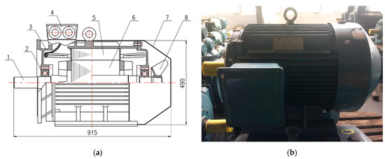
Figure 1.
The asynchronous motor of model YE3-250M-4 with power of 55 kW: simplified sketch (a) and photo (b). The components of the motor include the shaft (1), the bearing (2), the open-type end cover (3), the terminal box (4), the stator (5), the rotor (6), the motor end-plate (7), and the motor fan (8).

Table 1.
The experimental motor.
According to the international classification, the cooling system of this motor is IC411: design of the cooling circuit—cooling of the outer surface of the motor; ways of movement the secondary coolant—self-cooling.
The stator (Figure 2) is the outer stationary part of the motor. It consists of the outer cylindrical frame, the magnetic path, and a set of insulated electrical windings. For this motor variant, the typical approach involves utilizing external cooling. This cooling process takes place through the finned surface of the motor using either natural or forced convection methods. The forced convection mechanism is facilitated by an external fan impeller that is mounted on the rotor shaft. This impeller ensures the circulation of air along the ducts of the motor housing’s finned surface, as depicted in Figure 2a [30,53]. However, it is important to note that this external cooling method leads to uneven temperature distribution in the electric motor, resulting in an inability to achieve a notable power boost while lowering the coolant temperature. Furthermore, the requirement for efficient cooling leads to motor weight increases [24].

Figure 2.
Stator of an asynchronous motor (model YE3-250): frontal (a) and general view (b). As shown, there are the motor housing (1), the terminal box (2), and the stator (3).
2.2. General Description of the Experimental Setup
After analyzing the schemes of different types of cooling systems, the cooling system for the motor YE3-250M-4 was selected as shown in Figure 3. This cooling system is a three-circuit low-temperature system that allows the temperature of the cooling water circuit to be decreased to a temperature equal to or lower than the ambient temperature (tcool = 0–45 °C). This setup includes a motor, a load (generator), an electromechanical parameter control and management system, distribution valves (utilized for regulating the distribution of cooling water between the separate cooling circuits), measurement systems (computerized tools designed for the monitoring, control, and recording of measured data), and an industrial chiller (used to provide water cooling and temperature regulation at the cooling system’s inlet).
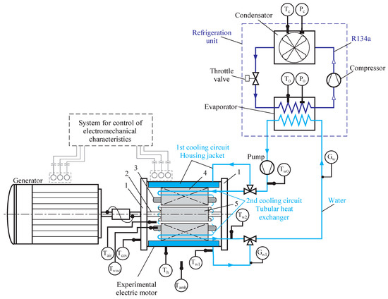
Figure 3.
Scheme of the experimental setup including temperature sensors (T) and pressure sensors (P). The experimental motor consists of a cover (1), a shaft (2), the winding (3), the stator (4), and the rotor (5). Temperature sensors: air temperature inside the motor (Tair), winding temperature (Twind), rotor bearing temperature, cover (Tcov), housing temperature (Th), ambient air temperature (Tamb), water temperature at the outlet of the first cooling circuit (Tw1), water temperature at the outlet of the second cooling circuit (Tw2), cooled water temperature after chiller (Tw0), evaporation temperature and pressure of the refrigerant in the refrigeration machine (T0, P0), and condensation temperature and pressure of the refrigerant in the refrigeration machine (Tc, Pc).
The developed motor cooling system consists of three cooling circuits:
- 1st circuit—water cooling of the motor housing;
- 2nd circuit—water cooling of the stator (Figure 3; part 4). Cooling tubes should be installed in the stator and,
- 3rd circuit—air cooling of the rotor (Figure 3, part 5) (self-cooling or self-ventilated). The air is cooled by the tubes of the cooling system of the second circuit (stator).
The water is fed through the manifold to the ducts of the motor housing (the first circuit of the cooling system) and the stator heat exchanger–cooler (the second circuit of the cooling system) by a circulation pump. The manifold consistently channels water to efficiently maintain the optimal flow speed and heat dissipation in both the first and second circuits of the cooling system, thereby cooling the stator air and motor housing effectively.
The first circuit of the motor cooling system consists of flat ducts connected in series inside the motor housing. The connection of the ducts is successive in the form of a “coil pipe”. For the connection of ducts, special slots (in the form of cuts) are used. The water supply and removal were carried out through fittings located on one side in several ducts.
The second circuit of the motor cooling system is a stator heat exchanger-cooler in the form of small-diameter coil pipes. The water supply and removal into the tubes of the heat exchanger is carried out from one side. To connect the pipes, special “arcuate tube” connections are used. Such connections should have an elongated part of the straight tube and an arcuate tube that connects two adjacent tubes. This way of installing the heat exchanger will ensure efficient cooling not only for the stator (Figure 3, part 4) but the air that circulates inside the motor. The heat exchanger tubes are located inside the stator metal and near the motor housing. The water velocity in the tube must be not less than 1.0 m/s high enough to ensure intensive air cooling inside the motor.
The third circuit of the motor cooling system is the rotor and the stator winding frontal parts (Figure 3, part 3) air cooling, which circulates intensively inside the motor in two air chambers. This is a method of self-cooling where the coolant airflow depends on the motor’s peripheral speed due to the rotor speed. In this case, the air is cooled by the tubes protruding parts (“arcuate tubes”) of the second circuit heat exchanger of the motor cooling system. Such a cooling method will significantly reduce the rotor and the stator winding frontal parts temperature in comparison with the standard motor cooling method.
The first and second circuits heated water of the cooling system is discharged to the wastewater collector and then enters the refrigeration unit. Then, the cooled water is fed back to the motor by the circulation pump. The refrigerating machine also consists of a condenser, a compressor, and a throttle valve. The refrigerating machine is switched on also when the motor is switched to a large load (power). This is due to the fact that with increasing motor power, absolute heat losses increase, the temperatures of the elements inside the motor increase, and the motor efficiency changes. The refrigerating machine condenser is air-cooled.
The refrigerating system selection was carried out considering variable climatic conditions. For experimentation of the cooling system, the industrial chiller LNSX-0.3 refrigerating system was used for water cooling. The system has a cooling capacity (Q0st) of 9.25 kW, a water flow (Vw) of 2.0 m3/h (0.56 kg/s), a pump power (Npump) of 0.55 kW, a compressor power (Ncomp) of 2.68 kW, and uses the refrigerant R134a.
The classification of the developed cooling system is according to IEC 60034-6: 1991 [54]—IC71W (IC7A1W7): design of the cooling circuit—integrated heat exchanger (using a remote medium); ways of the primary coolant flow—self-cooling; primary coolant—air; secondary coolant—water (Figure 3). This motor cooling system consists of a closed primary cooling line and an open secondary cooling line using a remote medium. These cooling characteristics are associated with the characteristics of the primary coolant flow. The secondary coolant flows during independent cooling and the coolant flows under pressure. This means that the primary coolant, water, which circulates in the system (motor housing—first circuit; heat exchanger tubes—second circuit) and is cooled by a refrigeration machine, where a secondary refrigerant circulates. Air also circulates inside the motor, which additionally removes heat from the motor elements (self-cooling) and transfers it upon contact with the first and second circuits of the cooling system).
2.3. The Geometry of the Motor Housing Ducts and the Location of the Stator Cooling Tubes
The first circuit of the motor cooling system consists of special geometry ducts located inside the motor housing (motor cooling jacket). The geometry of these channels was chosen from the existing and industry-applied types of duct geometry for motor water cooling systems. In this project, one of the most common types of ducts was selected as shown in Figure 4.
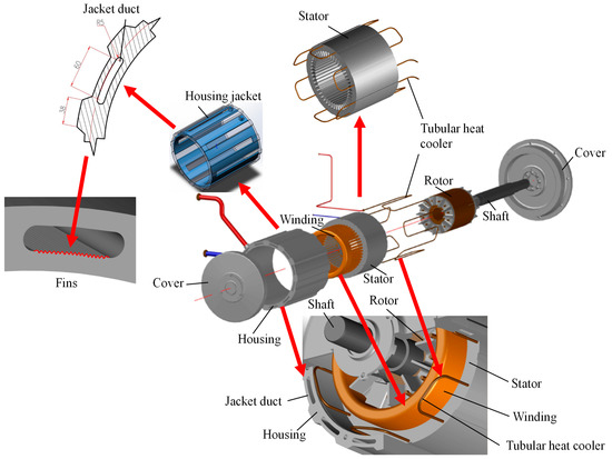
Figure 4.
The structure of the experimental cooling system.
To increase the area of the heat transfer surface and intensify the heat transfer, finning on the side of the water coolant was used. The geometry of such fins can be different (e.g., round form, oval form, and triangular form). The direction of the fin should be along the duct. The selection of fins with an oval form is particularly strategic. Oval fins are known for their ability to efficiently conduct heat from the solid surfaces of the housing to the adjacent fluid, making them highly effective in convective heat transfer scenarios. This choice aligns with established industry practices for motor water cooling systems, where the inclusion of fins in duct geometry is a well-regarded method for improving cooling performance.
The duct dimensions (Figure 4) based on existing technical solutions for this type of cooling system are selected with the following defining parameters are
- inner diameter of the motor housing (Din)—400 mm;
- motor housing material—Aluminum alloy 6063-T5;
- optimum channel water speed—0.1–0.5 m/s.
These parameters were selected during design and are determined by the technical requirements for water cooling systems in vehicle engines.
The first circuit channels of the motor cooling system are connected in series and in general are multi-pass heat exchangers (Figure 4). This solution is technologically the most straightforward from the manufacturing point-of-view for the motor housing [55,56]. It should be noted that, for example, a multi-pass heat exchanger with water supply through the channel or in each channel is more efficient [17]. However, this variant is more complicated, which in turn complicates the cooling system operation.
The second circuit tubes of the motor cooling system are also combined into a coil-type heat exchanger. It is more effective to supply heat to each tube or through a tube [57,58]; however, the variant in the form of a coil is chosen as the most technologically straightforward (Figure 4).
The peculiarity of this heat exchanger is that the tubes are installed directly in the motor stator, which increases the cooling efficiency. The tube selected for installation inside the stator has an inner diameter (din) of 4.8 mm, an outer diameter (dout) of 6.0 mm, and is constructed out of copper.
The recommended co-installation of the heat exchanger of the second circuit of the motor cooling system to the first circuit channels is a “staggered” type as shown in Figure 4. The number of ducts and tubes of the heat exchanger must be equal. This arrangement is effective from the point of view of removing heat from the motor stator and makes it possible for the first and second cooling circuits to operate simultaneously. This makes it possible to study the joint operation of the cooling system for the first and second circuits to determine the optimal operating conditions. The schematic design of the motor cooling system is shown in Figure 4.
It should be noted that iron losses are primarily associated with the core material and the alternating magnetic field. Copper tubes themselves are not likely to have a direct impact on magnetic saturation in the stator. Magnetic saturation is more related to the magnetic properties of the stator core material. The design of the stator core and the choice of materials are crucial factors in preventing or managing magnetic saturation. If the copper tubes are part of a cooling system, they may experience induced currents due to the changing magnetic fields in the near. However, this is a common reason in the design of such systems, and measures such as insulating materials or specific design features are often used to minimize these induced currents. Thus, while copper tubes cannot directly impact iron losses or magnetic saturation in the stator, their attendance in a cooling system could potentially lead to induced currents. However, these issues are usually managed through thoughtful design and material choices in the overall system to ensure efficient and safe operation.
3. Plan of the Experiment
3.1. Test Procedure and Conditions
Throughout the testing process, the motor underwent loadings within the range of 55 to 90 kW. Simultaneously, the rotational frequency, water flow rate, and temperature were maintained. This allowed for the comprehensive measurement of all electromechanical and thermal characteristics of the motor with the cooling circuits and the refrigeration apparatus attached (Table 2). The arrangement of the sensors for measuring the cooling circuit temperatures is shown in Figure 3.
Table 2.
The conditions of the experiment.
The experiment’s duration (3 h) was determined by the necessity to assess the cooling system’s efficiency under constant, extended periods of operation. Data collection was conducted at 15 min intervals and calculated as an average over a specific time window. The motor’s rotation frequency was consistently maintained in accordance with the standardized testing protocol (IEC/EN60034-1/-29 standards [59]).
In practical terms, maintaining a constant rotation frequency during the tests serves several purposes. Firstly, it replicates real-world scenarios where motors in certain applications operate at a specific rotational speed. This controlled setting allows for a focused evaluation of the cooling system’s performance under conditions relevant to its intended use. Secondly, a steady rotation frequency facilitates the accurate measurement of various parameters, including temperature and heat dissipation, enabling a thorough analysis of the cooling system’s efficiency.
The tests were carried out at a steady power output, ranging from 55 kW to 90 kW, to reflect typical motor power levels for light vehicles. The selection of water temperature was based on the technical limitations of developing and future thermal insulation designs for this motor type. To emulate real-world operating conditions, the ambient air temperature and humidity were monitored during experimentation. The water flow rate was chosen and maintained at the highest possible level, considering the maximum hydraulic resistance values within the secondary circuit stator cooler tubes, as these are limited by the technical specifications of the motor design.
To determine the motor’s effectiveness under the specified load conditions, the following characteristics were ascertained: motor efficiency (ηe), constant heat losses (Pk), losses within the iron components (Pi), losses in the stator winding (Ps), and losses within the rotor winding (Pr). Simultaneously, to evaluate the cooling system’s efficiency, the following parameters were examined: motor winding temperature (Twind), internal air temperature within the motor housing (Tair), heat transfer coefficient between air inside the motor and coolant (k), convective heat transfer coefficient (h), thermal resistance (Rcs), the ratio of the temperature difference between the winding and the average temperature of the cooling water to the quantity of heat removed within the cooling circuits), and heat flux (qcs). The convective heat transfer coefficient was calculated by measuring the heat transfer rate between the motor components and the air, the surface area, and the temperature difference between the surface and the air.
The dimensionless winding temperature was defined as:
where Tmax—the maximum permissible temperature according to the motor’s thermal class
A computerized monitoring and data registration system provided the connection of temperature sensors and a motor electromechanical monitoring system throughout the experiment.
Taking into consideration the test equipment’s power, the machine was initiated with characteristics corresponding to its machine type, and all specific parameters outlined by the manufacturer were established. Subsequently, a functional test was executed in alignment with the IEC/EN60034-1/-29 standards. A functional test in the context of motor testing involves a systematic examination of the motor’s operational performance under predefined conditions. The purpose of this test is to ensure that the motor functions as expected and meets the specified criteria. After that, a load characteristic was established during actual operational conditions, and the efficiency was computed by accounting for individual losses according to the IEC 60034-2-1/IEEE-112-7 standards [60]. Post-testing, a visual inspection of motor components was carried out.
The motor efficiency was defined as follows:
where P1 is the input motor power, P2 is the output motor power, and P1–P2 is the totally power loss (Pt). The power loss (Pt) is the sum of the individual losses:
where Pk is the permanent losses, PS is the stator winding losses depending on the load, PR is the rotor winding losses, and PLL are the additional losses.
Permanent losses (Pk) are the no-load losses excluding no-load losses in the windings (PS0) with winding resistance (R) and no-load current (I0):
where Pk is the sum of friction and ventilation losses (Pfw) and iron losses (Pfe); P0 is no-load power losses.
Iron losses at the desired load point are determined from the no-load curve at voltage Vi reduced by the ohmic voltage drop in the primary winding:
Losses in the stator winding depend on the load Ps.
The losses in the stator winding that are not reduced to the normal temperature of the coolant are determined for each load point using the values of current (I) and winding resistance (R) corresponding to each load point:
For each load point, the coolant temperature is considered by means of the coefficient kθ, which represents a coefficient that adjusts the stator winding losses based on the coolant temperature (Tw) [60]:
where Twind—winding temperature; Tw0—water temperature (before motor).
The losses in the rotor winding (Pr), normalized to the normal temperature of the coolant, are determined for each load point:
where s is the slip in an induction motor, indicating the difference between synchronous speed and actual rotor speed.
3.2. Measurement System and Instrumentation
During the experiment, data were collected through a network of sensors and monitors. We employed thermocouples and pressure sensors, which were managed and read by 8-channel controllers (И8-TC). This controller utilized an RS485 communication interface to transmit the data to a computer through a USB, which subsequently processed the information using SSD 3.5 Regmik software. The resultant measurement data was documented in measurement protocols and visualized graphically. To facilitate data input and processing, a dedicated database was set up. Details regarding the precision and measurement error characteristics of the control and measurement devices can be found in Table 3. To measure air temperature and humidity, a thermocouple (Tamb, Figure 3) and a psychrometer installed close to the motor housing were also used. The data were recorded by the measurement system.
Table 3.
Instruments of the measurement system.
The air temperature inside the motor was measured in the air chamber area located between the motor cover and the frontal part of the rotor end-winding (Figure 5). The temperature sensor did not touch the inside surfaces to ensure that the data obtained was solely the air temperature.
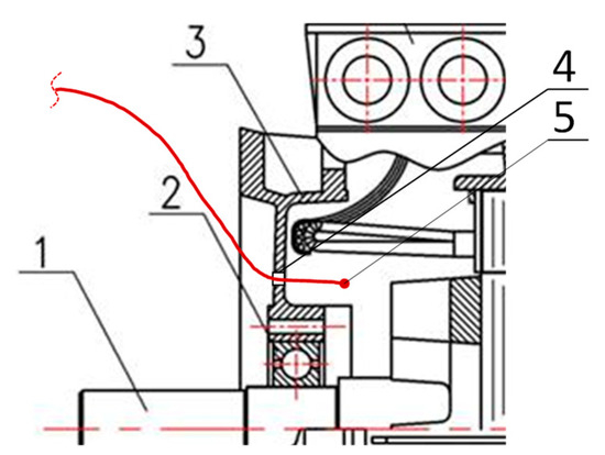
Figure 5.
Installation method for sensor TT/1 for the measurement of the air temperature inside the motor. The schematic includes the motor shaft (1), the bearing (2), the open-type end cover (3), the technological hole (4), and the temperature sensor (5).
For measuring water flow in the cooling system’s primary and secondary circuits, a rotameter was used. This device is designed to gauge volume flow in uniform flows with an acceptable measurement error. Additionally, the volume flow was measured by determining the filling time of a specialized measuring container (volume method).
3.3. Measurement Uncertainty
The precision of experimental outcomes depends on systematic error, which in turn is influenced by methodological errors and the inaccuracies inherent in measuring devices. The relative error was evaluated using a confidence probability value of p = 0.95. For evaluating the precision of measurement results when dealing with a limited number of observations (n ≤ 20), and if the uncertainty of individual measurements follows a normal distribution, the Student’s t-distribution was used [61,62,63].
The relationship for calculating the maximum relative error in indirectly measuring the required quantity y = f(x1, x2, … xi, … xn) was calculated as в the value of the confidence interval Δ0.95:
where tp—value of the relative interval, depending on the number of measurements for P = 0.95; —estimate of the mean square deviation of the measurement result.
Table 4 presents the maximum values of measurement uncertainties for various sensors at different power levels in the experiment.
Table 4.
Maximum values of the uncertainty of the measures in the experiment.
Air temperature inside the motor (Tair):
- Uncertainty increases with higher power levels, ranging from 0.86% at 55 kW to 2.46% at 90 kW.
- The increase in uncertainty could be attributed to the higher thermal stresses and complexities in heat dissipation as the motor operates at increased power levels.
Winding temperature (Twind):
- Similar to Tair, uncertainties show an increasing trend with higher power levels.
- The precision in measuring winding temperature is affected by the escalating thermal demands on the motor at higher loads.
Rotor bearing temperature, cover (Tcov):
- The trend is similar, with higher uncertainties observed at higher power levels.
- The rotor bearing temperature, influenced by the motor’s operational load, exhibits increased uncertainty under heavier demands.
Housing temperature (Th):
- Uncertainty remains relatively low across different power levels.
- The housing temperature, being a more stable parameter, shows consistent and manageable uncertainties.
Ambient air temperature (Tamb):
- The uncertainties vary, but interestingly, Tamb shows a decrease at 75 kW compared to 65 kW.
- This could be due to the specifics of the experimental conditions or the influence of external factors on ambient air temperature measurements.
Water temperatures (Tw1 to Tw2):
- Variations in uncertainties are observed across different water temperature measurements.
- These uncertainties could be influenced by factors such as water flow rates and heat exchange efficiency within the cooling circuits.
Stator temperature (Tst):
- Uncertainty shows a fluctuating pattern across different power levels.
- This fluctuation could be linked to the intricacies of stator temperature regulation under varying loads.
Input power (P1) and output power (P2):
- Uncertainties vary, and higher uncertainties are noticeable at certain power levels.
- The precision in measuring input and output power may be influenced by factors like electrical losses and measurement device accuracy.
4. Results and Discussion
4.1. Analysis of Experimental Data of the Electric Motor Cooling System
The experimental investigation focused on evaluating the cooling system’s performance for an electric motor operating at varying load conditions. The study revealed significant insights into the relationship between motor power, winding temperature, and cooling efficiency. The motor cooling system was evaluated based on the heat flux and temperature of the stator winding.
The cooling system demonstrated the ability to maintain motor efficiency within acceptable limits higher than 92.2% across varying power levels (55–90 kW), ambient air temperatures in the range of 22–31 °C, and ambient air humidity in the range of 30–60%. Several key observations were made under these varying conditions. The motor efficiency decreased as both power (Figure 6a) and winding temperature (Figure 6b) increased. The reduction in efficiency was also more visible at higher power levels and under continuous loads (Figure 6c). For instance, at 55 kW, the efficiency was observed as 94.5%. This decreased to 92.5% at 90 kW (Figure 6a). It should be said that considering the power of the compressor of the refrigeration machine (RM), the efficiency of the installation decreases by 0.7–1.0% (Figure 6a).
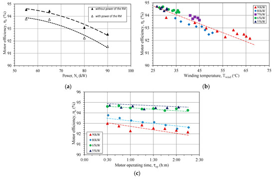
Figure 6.
Motor efficiency versus motor power (a), winding temperature (b), motor operation time (c). RM—refrigeration machine.
The decrease in the motor’s efficiency resulted in the increase of a winding temperature up to 67 °C (Figure 7a) when applying a motor power of 90 kW for a 3 h duration. During the operation time, a gradual temperature increase of 10–20 °C was observed. Measurements were taken when applying a motor power constantly for a 3 h duration. The test time was chosen based on the generally accepted practice of conducting experimental studies with motors that operate under variable loads (1–3 h) [31,37,57].
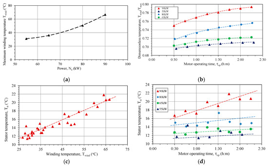
Figure 7.
Winding temperature versus motor power (a), dimensionless temperature versus motor operation time (b), stator temperature versus winding temperature (c), and stator temperature versus motor operation time (d).
After this time, the quasi-equilibrium state of the motor’s operation was observed. The cooling system provided a significant margin for producing increased motor power, as indicated by the dimensionless winding temperature staying below the critical threshold of 1.0 (Figure 7b). The maximum dimensionless winding temperature reaches 0.79 at a power rating of 90 kW, which corresponds to a temperature margin of 21%. A previous study obtained the dimensionless winding temperature in the range between 0.74 and 0.95 [3].
Stator and winding temperatures remained within safe limits, even under high-power operations, and did not exceed the maximum allowable limit for the thermal insulation class F (155 °C). The system effectively controlled and managed temperature variations. The increasing winding temperature correlates linearly with the stator temperature (Figure 7c), which is also increasing during the experiment duration (Figure 7d). The air temperature between the motors cover and winding was also increasing when power and duration were increased (Figure 8a,b). The increase was in the range of 34.3 °C to 96.6 °C, with respect to motor’s power and operation time. The heat flow from rotor contributed to the increasing air temperature. The same behavior was reported in other studies, when the rise of rotor temperature compared to the air temperature exceeded 50 °C. It is crucial to point out the significance of integrated rotor and stator cooling as the efficient solution [28,46]. The integrated rotor and stator cooling system plays a pivotal role in dissipating the heat generated during motor operation, ensuring a harmonious thermal environment. By facilitating effective heat transfer and maintaining temperature levels within prescribed limits, this system enhances the motor’s reliability, longevity, and operational efficiency. Its importance extends beyond conventional cooling methods, providing a comprehensive solution to the intricate thermal challenges posed by high-power and extended-duration operations.

Figure 8.
Air temperature versus motor operating time (a), and winding temperature (b).
The overall convective heat transfer coefficient to the air inside the motor ranges between 46 and 80 W/(m2 °C), which correlates quite well with the previously reported data (110 to 130 W/(m2 °C)) [64,65]. The Reynold’s number for the 1st circuit (ducts into the motor housing) is 29·103, and for the 2nd circuit (tubes installed in the stator) is 6.3·103. At the same time, Nusselt number to the air inside the motor is from 250 to 515. However, the precise data of the convective heat transfer of air requires a different experimental set up, which was not used for this study.
The Reynold’s number for the 1st circuit (ducts into the motor housing) is 29·103, and for the 2nd circuit (tubes installed in the stator) is 6.3·103. At the same time, Nusselt number to the air inside the motor is from 250 to 515. However, the precise data of the convective heat transfer of air requires a different experimental setup, which was not used for this study.
Reynolds number was established as:
where: w is the flow speed; ν is the kinematic viscosity of the fluid; Dekv is an equivalent diameter (m), equal to the diameter of the ducts.
Nusselt number was established as:
where: h is the convective heat transfer coefficient of the flow; λ is the thermal conductivity of the fluid.
The heat flux was a critical parameter indicating the system’s cooling efficiency and reached a maximum value exceeding 20 kW/m2. The heat flux increased from 5.80 kW/m2 to 21.30 kW/m2, with respect to the motor’s power and operation time (Figure 9). The experimental motor’s coolant temperature (Tw0) consistently registers below ambient temperature (Tamb). It is crucial to note that the experimental motor is not isolated, and the cooling dynamics are impacted by various factors. Specifically, the first cooling circuit, responsible for cooling the motor housing, exhibits temperatures lower than the ambient temperature. Moreover, the ambient conditions, including ambient temperature (Tamb) and humidity (φamb), play a significant role in influencing the cooling capacity of the refrigeration unit. The interplay of these ambient factors has a direct impact on the heat flux values, affecting the heat transfer calculations through the cooling water.
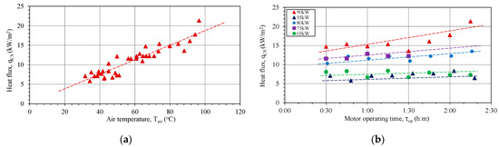
Figure 9.
Heat flux versus air temperature inside the motor (a), and for different motor powers and operation times (b).
It should be noted that the temperature of the air inside the motor’s interior continued to rise during the operation time (Figure 8a,b). The air temperature has the highest values among other elements of the motor (housing, stator, and windings). This means that the rotor has an even higher temperature and requires more intensive cooling, thereby increasing the heat flux levels. The analysis of recent research has shown that the heat flux levels can be increased by more than 10 times by using direct cooling methods [28].
The developed cooling system, comprising of water- and air-cooling circuits, demonstrated its ability to effectively manage temperature according to the thermal insulation class F and maintain motor efficiency under varying load conditions exceeding the base power by more than 63%. A recent review has shown that the power of electric motors can be improved by a factor of 3–5 or even more by managing temperature control of the windings [11].
4.2. The Power-to-Dimension Ratio
Based on the comprehensive analyses of the experimental data and the performance characteristics of the cooling system for electric motors, it is evident that the utilization of such an advanced cooling system holds the potential to significantly increase the power-to-dimension ratio (PDR) of electric motors, while also considering the capability to cool to lower temperatures. Several key factors support this conclusion. Moreover, it is important to have a cooling system margin. The consistently low relative winding temperature remaining below 1.0 (Figure 10), indicates that the cooling system possesses a substantial margin for accommodating increased power outputs. This suggests that the cooling system can support further enhancements in the PDR. Wherein despite the rise in thermal resistance, the cooling system effectively maintains temperature control within safe parameters. This management ensures that the motor’s performance remains stable and reliable, even as power levels escalate.
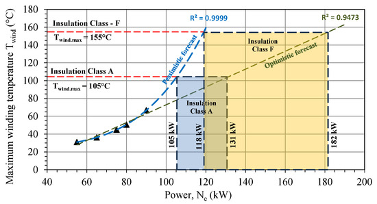
Figure 10.
The maximum winding temperature versus motor power. A forecast for increasing power in different insulation class.
The cooling system’s ability to cool to lower temperatures is a crucial factor in enabling the motor to withstand higher power outputs. The data indicates that the cooling system can efficiently manage temperature extremes, paving the way for increased power density.
The modification in design involving the adoption of an aluminum motor housing, combined with a boost in motor output power, results in increasing the PDR. At the same time, when increasing the power to 90 kW, the PDR increases to 0.45 kW/kg.
It should be noted that adopting a three-circuit cooling system necessitates modifications to specific motor components, including the motor housing and covers. Additionally, alterations are required for the installation of secondary circuit tubes into the stator metal. Design improvements are also required to enhance the internal components’ sealing. Furthermore, the choice of aluminum alloy for the motor housing and covers is rational when using water cooling, as aluminum has a superior thermal conductivity of 209 W/(m·K), enabling it to support a higher heat flux for the cooling system. It also significantly reduces the weight of the motor (up to 40% depending on the application). However, this imposes additional requirements on the sealing of the motor. It is important to note that practical implementation should consider factors such as thermal limits, materials, manufacturing constraints, and specific application requirements.
The using of aluminum alloy for the motor housing and covers introduces specific considerations, particularly concerning additional sealing requirements. While the aluminum alloy offers advantages such as lightweight and good thermal conductivity, addressing sealing requirements becomes crucial for maintaining the motor’s performance and longevity. A holistic approach that considers thermal expansion, corrosion resistance, gasket compatibility, mechanical stresses, assembly techniques, compliance with standards, environmental factors, and serviceability will contribute to the successful implementation of aluminum alloy in motor housing and covers.
An examination of the stator winding temperatures, as acquired from the experiment, reveals a notable temperature margin. Analyzing the experimental data, we can make conclusions while considering both a pessimistic and optimistic outlook for enhancing motor power (Figure 10). The presented forecasts are obtained by the method of extrapolated experimental data and represent polynomial and linear dependences as the minimum and maximum power values at the same temperature of the stator winding, respectively. As a result, when the maximum winding temperature reaches 155 °C (in insulation class F), the achievable motor power ranges between 118 and 182 kW. This provides a PDR ranging from 0.59 to 0.90 under the optimistic scenario, which is 4.2 to 6.4 times higher than that of a standard asynchronous motor with external air cooling and exceeds the maximum performance of this type of industrial motor (Figure 11).
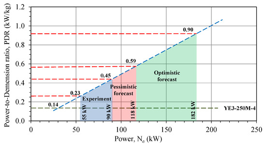
Figure 11.
Power-to-dimension ratio versus motor power.
It is also possible to assess the potential for using a cooling system while considering a reduction in the motor’s insulation class. By reducing the insulation class to class A, with a maximum winding temperature of 105 °C, an increase in power ranging from 105 to 131 kW is feasible. Lowering the insulation class would considerably extend the motor’s lifespan by up to 2.5 times, considering the recommendations listed in [1,2].
It is worth noting that comparing the PDR of the experimental asynchronous motor with that of a synchronous transport motor of type iEM featuring air cooling [4], the potential increase in PDR is up to 3.32 in the optimistic scenario and up to 2.15 in the pessimistic scenario (Figure 12). This exceeds the baseline value by 2.6 to 4.0 times.
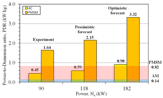
Figure 12.
Comparison of the power-to-dimension ratio for experimental an asynchronous motor (AM) and a transport permanent magnet synchronous motor (PMSM) [4] with an air cooling system.
It should be noted that there are a number of promising solutions for cooling systems. Increasing the cooling efficiency can be achieved by replacing the primary circuit with indirect cooling when the hot air from the interior of the motor is cooled down in the external heat exchanger on top of the motor housing. In this case, heat exchange is not limited by the geometry of the motor itself. This allows high specific power values for the motor to be achieved, which is of great importance for electric vehicle motors of all types. For example, this concept is used in the BMW i3 (IPMSM motor), Toyota Prius (IPSMSM motor), Sonata (PMSM motor), Tesla Roadster (AC IM motor), and Nissan Leaf (IPMSM motor), making it possible to increase the power-to-dimension ratio by up to 2.5–2.7 kW/kg [3,4,5].
While exact figures would require further detailed analysis and testing specific to a given motor design and cooling system, the observed trends and thermal management capabilities of the advanced cooling system suggest that a significant increase in power output (potentially exceeding 60%) and PDR (potentially well above the nominal values) is achievable.
The implementation of an advanced cooling system has the potential to significantly elevate the PDR of electric motors. By effectively controlling temperatures, dissipating heat, and ensuring stable operation, such cooling systems enable electric motors to operate at higher power levels while maintaining efficiency and reliability. This has substantial implications for a wide range of applications, including vehicles, ships, aircraft, and beyond, where maximizing PDR within a limited volume is of high importance.
4.3. Analysis of the Three-Circuit Cooling Unit
The analysis of experimental data concerning the cooling system capacity at various motor loads (Figure 13a) shows significant insights. When the motor operates at its nominal power of 55 kW, the heat load of the cooling system is 2.71 kW. However, increasing the power output by 63% (90 kW) rises the heat load to 6.10 kW (average value), meaning a notable 112% increase in cooling is required. This increase of the cooling load also includes the additional electromechanical losses related to decreased motor efficiency at higher power levels.
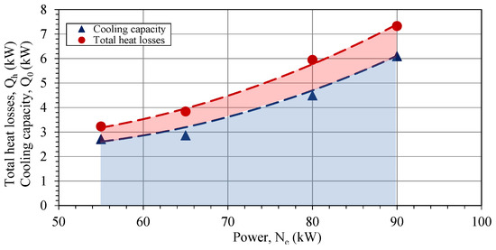
Figure 13.
Heat efficiency of the cooling system: comparison of the heat losses and heat capacity.
As can be seen from Figure 13a, the motor’s heat losses (red line) exceed the thermal capabilities of the cooling system for all the experimental points. The heat, which is not removed by the cooling system, was measured at 626 and 1234 W for 55 kW and 90 kW, respectively. The thermal efficiency of the cooling system, representing the ratio of heat removed by the cooling system to total heat losses, varied between 74% and 84% during the experiments (Figure 13b). Notably, the air-cooling system’s efficiency declared by the producer for a base motor of 55 kW stands at 80.3%. Therefore, increasing the motor power up to 90 kW and applying the three-circuit low-temperature cooling system fits the specified cooling efficiency.
It is important to highlight that the average efficiency of the cooling system was measured at 79.2%, indicating that more than 20% of the heat is not transferred to the water loop and is partially dissipated in the motor resulting in the gradual increasing of the air temperature inside the motor (Figure 8). The accumulation of the heat energy in the rotor risks overheating and failure during extended motor overloads exceeding 90 kW. The real values of the heat accumulated during the motor’s operation can be higher than the 20% indicated above. This requires an additional study when a detailed investigation of the rotor behavior is included. However, the main goal of this study was to determine the cooling system’s limitations, such as the maximum achievable engine power and its behavior under varying engine loads.
The obvious solution includes enhancing the air circulation and heat transfer inside the motor, achieved by integrating additional heat exchangers for the third circuit of the cooling system. Alternatively, a redesign of the heat exchanger elements in the first and second circuits to increase the heat-exchanging surface area could be considered. At the same time, the use of evaporative heat transfer and lower cooling temperatures is also a potential way to improve [4,28].
Refrigerants like CO2 or low-boiling refrigerants have the potential to provide efficient cooling due to their excellent heat transfer properties. At the same time, CO2 and some low-boiling refrigerants are environmentally friendly alternatives to traditional refrigerants that have a high global warming potential (GWP). Their lower GWP and reduced environmental impact align with the growing demand for sustainable and eco-conscious technologies. Simultaneously, the use of low-boiling refrigerants can potentially lead to more compact and lightweight cooling systems, which is advantageous in applications with space restrictions like vehicles, ships, and aircraft.
5. Conclusions
The experimental research of a cooling system for the asynchronous motor involved developing a three-circuit low-temperature cooling system. This system consists of water cooling for the motor housing, water cooling for the stator, and air cooling for the rotor and stator winding frontal parts. The system features an integrated heat exchanger where the primary coolant is air, and the secondary coolant is water. The geometry of the motor housing ducts and stator cooling tubes was carefully considered to optimize heat transfer and cooling efficiency. The study demonstrates the benefits of a low-temperature three-circuit cooling system for a 55-kW electric motor, achieving uniform temperature distribution, increased PDR, and increased motor performance by 63%.
The study shows that the cooling system effectively maintained motor efficiency from 94.5% to 92.5%, while the motor power increased from 55 kW to 90 kW. Despite a minor decrease in efficiency by 2.0%, the system demonstrated a significant margin for increased motor power while keeping winding temperatures within safe limits. Moreover, the maximum dimensionless winding temperature ratio reaches 0.79 at a power of 90 kW, corresponding to a temperature margin of 21%.
The observations showed the linear dependence between motor power and winding temperature, with a maximum temperature increase of 10–20 °C during the operation, followed by a quasi-equilibrium state. Notably, the winding temperatures remained below the critical threshold for thermal insulation class F (155 °C). The increasing winding temperature during the three hours of motor operation time is up to 67 °C. This means that the water-cooling loops can provide sufficient cooling for the stator and housing of the electric motor.
The convective heat transfer coefficient to the air inside the motor was estimated to be in the range of 46 to 80 W/(m2 °C). The heat flux, a critical parameter for cooling efficiency, reached values exceeding 20 kW/m2. A portion of the heat remains accumulated in the rotor, reaching 626 W at 55 kW, and 1234 W at 90 kW. The average cooling system efficiency is 79.2%, signifying that around 20% of heat is not transferred to water. This results in a gradual temperature increase, particularly in the rotor, posing a risk of overheating and failure during extended motor overloads above 90 kW. The motor’s heat losses surpass the cooling system’s capabilities. Solutions for such challenges may include enhancing air-cooling efficiency through additional heat exchangers. A study of the use of alternative refrigerants with higher heat evaporative transfer values and lower cooling temperatures is also a promising method for improvement.
The implementation of such an advanced cooling system has the potential to raise the PDR of electric motors significantly. By effectively managing temperatures, dissipating heat, and ensuring stable operation, these cooling systems open possibilities for higher power levels, particularly in vehicles, ships, and aircraft, where maximizing PDR within limited volume constraints is important. Implementing a three-circuit cooling system requires specific modifications to motor components, including the motor housing and covers. Design improvements are necessary to enhance the sealing of internal components. Due to its superior thermal conductivity, the choice of aluminum alloy for the motor housing and covers significantly reduces motor weight while supporting higher heat flux for the cooling system.
Analysis of the extrapolating data suggests that by reaching a maximum winding temperature of 155 °C (insulation class F), the achievable asynchronous motor power could range from 118 to 182 kW, resulting in a PDR ranging from 0.59 to 0.90. Lowering the insulation class to class A, with a maximum winding temperature of 105 °C, could achieve increased power output, ranging from 105 to 131 kW. This would considerably extend the motor’s lifespan by almost 2.5 times. At the same time, the potential PDR of the synchronous motor can be increased by up to 2.15–3.32 times. These improvements surpass the base value by a factor of 2.6 to 4.0, showcasing a performance on par with leading global analogues that boast PDR values ranging from 2.5 to 2.7.
Moreover, it is imperative to consider the potential advancements that novel cooling approaches could bring to the system. Exploring possibilities such as additive manufacturing techniques and enhanced cooling agents presents an avenue for optimizing the cooling efficiency of the motor. The integration of innovative cooling methods has the potential to further improve heat dissipation, enhance overall performance, and contribute to the development of more efficient and resilient motor cooling systems.
Author Contributions
Conceptualization, D.K. and I.T.; methodology, D.K., H.K. and I.T.; software, H.K.; formal analysis, D.K. and I.T.; investigation, D.K., H.K. and I.T.; resources, H.K.; writing—original draft preparation, D.K., I.T.; writing—review and editing, J.J.L., T.M.E. and I.T.; supervision, D.K; project administration, D.K. All authors have read and agreed to the published version of the manuscript.
Funding
This research did not receive any specific grant from funding agencies in the public, commercial, or not-for-profit sectors.
Data Availability Statement
Data are contained within the article.
Conflicts of Interest
The authors declare no conflict of interest.
Nomenclature
| RM | Refrigeration machine | |
| GWP | Global warming potential | |
| Symbols and units | ||
| PDR | Power-to-dimension ratio | kW/kg |
| Tair | Air temperature inside the motor | °C |
| Twind | Winding temperature | °C |
| Dimensionless winding temperature | ||
| Tmax | Maximum permissible temperature according to the motor’s thermal class | °C |
| Tcov | Rotor bearing temperature, cover | °C |
| Th | Housing temperature | °C |
| Tamb | Ambient air temperature | °C |
| Tw1 | Water temperature at the outlet of the first cooling circuit | °C |
| Tw2 | Water temperature at the outlet of the second cooling circuit | °C |
| Tw0 | Cooled water temperature after the chiller | °C |
| Tst | Stator temperature | °C |
| T0, P0 | Evaporation temperature and pressure of the refrigerant in the refrigeration machine | °C, kPa |
| Tc, Pc | Condensation temperature and pressure of the refrigerant in the refrigeration machine | °C, kPa |
| Q0st | Cooling capacity | kW |
| Vw0 | Total volume water flow rate | m3/h |
| Gw0 | Total Water mass flow rate | kg/s |
| Gw1 | Water mass flow rate in 1st cooling circuits | kg/s |
| Npump | Pump power | kW |
| Ncomp | Compressor power | kW |
| din | Inner diameter of the tubes | mm |
| dout | Outer diameter of the tubes | mm |
| Dekv | Equivalent diameter | mm, m |
| ηe | Motor efficiency | % |
| Pk | Permanent losses | kW |
| Pi | Losses within the iron components | kW |
| Ps | Losses in the stator winding | kW |
| Pr | Losses within the rotor winding | kW |
| PLL | Additional losses | kW |
| Pt | Totally power loss | kW |
| P0 | No-load losses | kW |
| PS0 | No-load losses in the windings | kW |
| Pfw | Ventilation losses | kW |
| Pfe | Iron losses | kW |
| R | Winding resistance | kW |
| I0, I | No-load current, current | A |
| k | Heat transfer coefficient between air inside the motor and coolant | W/(m2 °C) |
| h | Convective heat transfer coefficient | W/(m2 °C) |
| Rcs | Thermal resistance | K/W |
| qcs | Heat flux | kW/m2, W/m2 |
| P1 | Input power | kW |
| P2 | Output power | kW |
| kθ | Temperature coefficient | |
| Re | Reynolds number | |
| Nu | Nusselt number | |
| w | Flow speed | m/s |
| ν | Kinematic viscosity of the fluid | m2/s |
| λ | Thermal conductivity of the fluid | W/(m·K) |
References
- Toliyat, H.A.; Kliman, G.B. Handbook of Electric Motors, 2nd ed.; Marcel Dekker: New York, NY, USA, 2004; Volume 120. [Google Scholar]
- Lipo, T. Introduction to AC Machine Design; Wiley-IEEE Press: Hoboken, NJ, USA, 2018. [Google Scholar]
- Gronwald, P.O.; Kern, T.A. Traction Motor Cooling Systems: A Literature Review and Comparative Study. IEEE Trans. Transp. Electrif. 2021, 7, 2892–2913. [Google Scholar] [CrossRef]
- Wrobel, R. A technology overview of thermal management of integrated motor drives—Electrical Machines. Therm. Sci. Eng. Prog. 2022, 29, 101222. [Google Scholar] [CrossRef]
- Konovalov, D.; Tolstorebrov, I.; Eikevik, T.M.; Kobalava, H.; Radchenko, M.; Hafner, A.; Radchenko, A. Recent Developments in Cooling Systems and Cooling Management for Electric Motors. Energies 2023, 16, 7006. [Google Scholar] [CrossRef]
- Yu, Z.; Løvås, T.; Konovalov, D.; Trushliakov, E.; Radchenko, M.; Kobalava, H.; Radchenko, R.; Radchenko, A. Investigation of Thermopressor with Incomplete Evaporation for Gas Turbine Intercooling Systems. Energies 2023, 16, 20. [Google Scholar] [CrossRef]
- Zhu, G.; Jia, N.; Li, L.; Liu, T.; Xue, M.; Li, M. Cooling System Design Optimization of a High Power Density PM Traction Motor for Electric Vehicle Applications. J. Electr. Eng. Technol. 2021, 16, 3061–3068. [Google Scholar] [CrossRef]
- Thomas, R.; Garbuio, L.; Gerbaud, L.; Chazal, H. Modeling and design analysis of the Tesla Model S induction motor. In Proceedings of the Proceedings—2020 International Conference on Electrical Machines, ICEM 2020, Gothenburg, Sweden, 23–26 August 2020; pp. 495–501. [Google Scholar]
- Nategh, S.; Boglietti, A.; Liu, Y.; Barber, D.; Brammer, R.; Lindberg, D.; Aglen, O. A Review on Different Aspects of Traction Motor Design for Railway Applications. IEEE Trans. Ind. Appl. 2020, 56, 2148–2157. [Google Scholar] [CrossRef]
- Gai, Y.; Kimiabeigi, M.; Chuan Chong, Y.; Widmer, J.D.; Deng, X.; Popescu, M.; Goss, J.; Staton, D.A.; Steven, A. Cooling of automotive traction motors: Schemes, examples, and computation methods. IEEE Trans. Ind. Electron. 2019, 66, 1681–1692. [Google Scholar] [CrossRef]
- Deisenroth, D.C.; Ohadi, M. Thermal management of high-power density electric motors for electrification of aviation and beyond. Energies 2019, 12, 3594. [Google Scholar] [CrossRef]
- Huang, J.A.; Shoai Naini, S.; Miller, R.; Wagner, J.R.; Rizzo, D.; Sebeck, K.; Shurin, S. An Integrated Cooling System for Hybrid Electric Vehicle Motors: Design and Simulation. SAE Int. J. Commer. Veh. 2018, 11, 255–266. [Google Scholar] [CrossRef]
- Sano, S.; Yashiro, T.; Takizawa, K.; Mizutani, T. Development of new motor for compact-class hybrid vehicles. World Electr. Veh. J. 2016, 8, 443–449. [Google Scholar] [CrossRef]
- IEC 60034-6: 1991; Rotating Electrical Machines—Part 6: Methods of Cooling (IC Code). IEC: Geneva, Switzerland, 1991; 39p.
- IEC 60034-1:2022; Rotating Electrical Machines—Part 1: Rating and Performance. IEC: Geneva, Switzerland, 2022; 161p.
- Ponomarev, P.; Polikarpova, M.; Pyrhönen, J. Thermal modeling of directly-oil-cooled permanent magnet synchronous machine. In Proceedings of the Proceedings—2012 20th International Conference on Electrical Machines, ICEM 2012, Marseille, France, 2–5 September 2012; pp. 1882–1887. [Google Scholar]
- Sikora, M.; Vlach, R.; Navr´atil, P. The unusial water cooling applied on small asynchronous motor. Eng. Mech. 2011, 18, 143–153. [Google Scholar]
- Chong, Y.C. Thermal Analysis and Air Flow Modelling of Electrical Machines. Ph.D. Thesis, The University of Edinburgh, Edinburgh, UK, 2015. [Google Scholar]
- Catalog D 81.1: SIMOTICS GP, SD, XP, DP Low-Voltage Motors. 2021. 706p. Available online: https://cache.industry.siemens.com/dl/files/197/109749197/att_1094438/v1/Motors-D81-1-complete-English-12-2021-Update_2022-02.pdf (accessed on 8 December 2023).
- ABB Low Voltage Motors. Motor Guide. 2019. 112p. Available online: https://library.e.abb.com/public/1fd380f8ca8b4934ae3fa609d764fd33/21043_ABB_Motor_Guide_REV_D.pdf (accessed on 8 December 2023).
- Catalog ABB Low Voltage. Process Performance Motors According to EU MEPS. 2014. 124p. Available online: https://library.e.abb.com/public/23ff859eee0200c3c1257e1a002770a2/Catalog_Process_performance_acc_to_EU_MEPS_9AKK105944%20EN%2010_2014.low.pdf?filename=Catalog_Process_performance_acc_to_EU_MEPS_9AKK105944%20EN%2010_2014.low.pdf (accessed on 8 December 2023).
- ABB Technical Application Papers No.7. THREE-Phase Asynchronous Motors. Generalities and ABB Proposals for the Coordination of Protective Devices. 2008. 48p. Available online: https://library.e.abb.com/public/451760e552194a239c7fec9ebde3fd4a/1SDC007106G0201.pdf (accessed on 8 December 2023).
- Brook Cromoton. Series 10. Frame Size 56 to 450. 2012. 30p. Available online: https://www.brookcromptonmotors.com/products/brook-crompton-series-10 (accessed on 8 December 2023).
- WEG: Specification of Electric Motors. 2020. 68p. Available online: https://static2.weg.net/medias/downloadcenter/ha0/h5f/WEG-motors-specification-of-electric-motors-50039409-brochure-english-web.pdf (accessed on 8 December 2023).
- Marathon Electric Motors: IEC IE3 Motor Range. 2014. 20p. Available online: https://sahkonumerot.fi/8610137/doc/brochure/ (accessed on 8 December 2023).
- Bharat Bijlee: Low Voltage Motors. 2016. 86p. Available online: http://www.mittalmachinery.in/downloads/products/Bharat-Bijlee-Motors.pdf (accessed on 8 December 2023).
- Khan, B.; Goyal, A.; Kumar Chobey, A. Improving thermal withstanding capacity of three phase induction motor using NWCC method. Int. J. Res. -Granthaalayah 2014, 2, 40–51. [Google Scholar] [CrossRef]
- Wang, X.; Li, B.; Gerada, D.; Huang, K.; Stone, I.; Worrall, S.; Yan, Y. A critical review on thermal management technologies for motors in electric cars. Appl. Therm. Eng. 2022, 201, 117758. [Google Scholar] [CrossRef]
- Albers, T.; Bonnett, A.H. Motor temperature considerations for pulp and paper mill applications. IEEE Trans. Ind. Appl. 2002, 38, 1701–1713. [Google Scholar] [CrossRef]
- Bante, K.G.; Tarnekar, S.G. AC Motor cooling system Analysis Based on Application Case Study. Int. J. Eng. Invent. 2013, 2, 9–15. Available online: https://ijeijournal.com/papers/v2i8/B02080915.pdf (accessed on 8 December 2023).
- Catalog Winkelmann Elektromotoren. Cooling Methods for Motors. 2020. Available online: https://www.w-winkelmann.com/fileadmin/user_upload/cooling-methods.pdf (accessed on 8 December 2023).
- Nakahama, T.; Suzuki, K.; Hashidume, S.; Ishihashi, F.; Hirata, M. Cooling airflow in unidirectional ventilated open-type motor for electric vehicles. IEEE Trans. Energy Convers. 2006, 21, 645–651. [Google Scholar] [CrossRef]
- Borges, S.S.; Cezario, C.A.; Kunz, T.T. Design of water cooled electric motors using CFD and thermography techniques. In Proceedings of the 2008 International Conference on Electrical Machines, ICEM’08, Vilamoura, Portugal, 6–9 September 2008. [Google Scholar]
- Schiefer, M.; Doppelbauer, M. Indirect slot cooling for high-power-density machines with concentrated winding. In Proceedings of the Proceedings—2015 IEEE International Electric Machines and Drives Conference, IEMDC 2015, Coeur d’Alene, ID, USA, 10–13 May 2015; pp. 1820–1825. [Google Scholar]
- Liu, C.; Gerada, D.; Xu, Z.; Chong, Y.C.; Michon, M.; Goss, J.; Li, J.; Gerada, C.; Zhang, H. Estimation of Oil Spray Cooling Heat Transfer Coefficients on Hairpin Windings with Reduced-Parameter Models. IEEE Trans. Transp. Electrif. 2021, 7, 793–803. [Google Scholar] [CrossRef]
- Ghahfarokhi, P.S.; Podgornovs, A.; Kallaste, A.; Vaimann, T.; Belahcen, A.; Cardoso, A.J.M. Oil Spray Cooling with Hairpin Windings in High-Performance Electric Vehicle Motors. In Proceedings of the 2021 28th International Workshop on Electric Drives: Improving Reliability of Electric Drives, IWED 2021—Proceedings, Moscow, Russia, 27–29 January 2021. [Google Scholar]
- Lindh, P.; Petrov, I.; Jaatinen-Varri, A.; Gronman, A.; Martinez-Iturralde, M.; Satrústegui, M.; Pyrhonen, J. Direct Liquid Cooling Method Verified with an Axial-Flux Permanent-Magnet Traction Machine Prototype. IEEE Trans. Ind. Electron. 2017, 64, 6086–6095. [Google Scholar] [CrossRef]
- Deriszadeh, A.; de Monte, F. On heat transfer performance of cooling systems using nanofluid for electric motor applications. Entropy 2020, 22, 99. [Google Scholar] [CrossRef]
- Catalog D 81.2: SIMOTICS NEMA Motors. Low Voltage AC Motors Selection and Pricing Guide. 2019. p. 293. Available online: https://cache.industry.siemens.com/dl/files/390/109763390/att_1023414/v1/2019_NEMA_Catalog_D81-2_Online_May2020.pdf (accessed on 8 December 2023).
- Integral Powertrain Limite. Electric Powertrain. Available online: https://ehelix.com/electric-powertrains/ (accessed on 8 December 2023).
- H3X Technologies Inc. High Performance Electric Propulsion Systems. Available online: https://www.h3x.tech/ (accessed on 8 December 2023).
- Burress, T. Electrical Performance, Reliability Analysis, and Characterization; Project ID: EDT087; U.S. Department of Energy: Washington, DC, USA, 2017; p. 25. [Google Scholar]
- Kimiabeigi, M.; Long, R.; Widmer, J.D.; Gao, Y. Comparative Assessment of Single Piece and Fir-Tree-Based Spoke Type Rotor Designs for Low-Cost Electric Vehicle Application. IEEE Trans. Energy Convers. 2017, 32, 486–494. [Google Scholar] [CrossRef]
- Lehmann, R.; Künzler, M.; Moullion, M.; Gauterin, F. Comparison of Commonly Used Cooling Concepts for Electrical Machines in Automotive Applications. Machines 2022, 10, 442. [Google Scholar] [CrossRef]
- Jin, Y.; Song, Y.; Liu, Y.; Cui, W.; Sun, C. Design of low-pressure sand casting process for water-cooled motor shell in electric vehicle. In Proceedings of the Journal of Physics: Conference Series; IOP Publishing: Bristol, UK, 2021. [Google Scholar]
- Carriero, A.; Locatelli, M.; Ramakrishnan, K.; Mastinu, G.; Gobbi, M. A Review of the State of the Art of Electric Traction Motors Cooling Techniques. In Proceedings of the SAE Technical Papers; SAE: Warrendale, PA, USA, 2018. [Google Scholar]
- Chasiotis, I.D.; Karnavas, Y.L. Design, Optimization and Modelling of High Power Density Direct-Drive Wheel Motor for Light Hybrid Electric Vehicles; IntechOpen: London, UK, 2017. [Google Scholar]
- Stone, G.C.; Culbert, I.; Boulter, E.A.; Dhirani, H. Electrical Insulation for Rotating Machines: Design, Evaluation, Aging, Testing, and Repair, 2nd ed.; John Wiley & Sons: Hoboken, NJ, USA, 2014; Volume 9781118057063, pp. 1–643. [Google Scholar]
- Liu, C.; Xu, Z.; Gerada, D.; Li, J.; Gerada, C.; Chong, Y.C.; Popescu, M.; Goss, J.; Staton, D.; Zhang, H. Experimental Investigation on Oil Spray Cooling with Hairpin Windings. IEEE Trans. Ind. Electron. 2020, 67, 7343–7353. [Google Scholar] [CrossRef]
- Davin, T.; Pellé, J.; Harmand, S.; Yu, R. Experimental study of oil cooling systems for electric motors. Appl. Therm. Eng. 2015, 75, 1–13. [Google Scholar] [CrossRef]
- Hari, D.; Brace, C.; Vagg, C.; Akehurst, S.; Ash, L.; Strong, R. Development and testing of a low cost high performance hybrid vehicle electric motor. In Proceedings of the SAE Technical Papers; SAE: Warrendale, PA, USA, 2013. [Google Scholar]
- Tüysüz, A.; Meyer, F.; Steichen, M.; Zwyssig, C.; Kolar, J.W. Advanced Cooling Methods for High-Speed Electrical Machines. IEEE Trans. Ind. Appl. 2017, 53, 2077–2087. [Google Scholar] [CrossRef]
- Bonnett, A.H. Operating temperature considerations and performance characteristics for IEEE 841 motors. IEEE Trans. Ind. Appl. 2001, 37, 1120–1131. [Google Scholar] [CrossRef]
- IEC 60034-6:1991; Rotating Electrical Machines: Methods of Cooling. IEC: Geneva, Switzerland, 1991.
- Pechanek, R.; Bouzek, L. Analyzing of two types water cooling electric motors using computational fluid dynamics. In Proceedings of the 15th International Power Electronics and Motion Control Conference and Exposition, EPE-PEMC 2012 ECCE Europe, Novi Sad, Serbia, 4–6 September 2012; pp. LS2e.41–LS42e.45. [Google Scholar]
- Kindl, V.; Pechanek, R.; Bouzek, L. Cooling of new designed machine. In Proceedings of the 13th International Symposium on Mechatronics, MECHATRONIKA 2010, Trencianske Teplice, Slovakia, 2–4 June 2010; pp. 95–98. [Google Scholar]
- Crowell, J.R.; Johnson, W.R.; Sontag, D.R.; Matthew, M.; Marker, T.K.; Basu, A.H. Liquid Cooled Electric Motor Frame. EU Patent EP 0859447A1, 19 August 1998. [Google Scholar]
- James, R.C.; Matthew, M.D.; Walter, R.J.; Tlmothy, K.M.; Darrell, R.S.; Ajoy, K.B. Liquid Cooled Electric Motor Frame. US Patent US005859482A, 12 January 1999. [Google Scholar]
- IEC 60034-29:2008; Rotating Electrical Machines—Part 29: Equivalent Loading and Superposition Techniques-Indirect Testing to Determine Temperature Rise. IEC: Geneva, Switzerland, 2008; 58p.
- IEC 60034-2-1:2014; Rotating Electrical Machines—Part 2-1: Standard Methods for Determining Losses and Efficiency from Tests. IEC: Geneva, Switzerland, 2014; 186p.
- Moffat, R.J. Describing the uncertainties in experimental results. Exp. Therm. Fluid Sci. 1988, 1, 3–17. [Google Scholar] [CrossRef]
- Mandel, J. The Statistical Analysis of Experimental Data; Interscience Publishers: Geneva, Switzerland, 1964. [Google Scholar]
- Meyer, S.L. Data Analysis for Scientists and Engineers; Wiley: Hoboken, NJ, USA, 1975. [Google Scholar]
- Goldberg, O.D.; Sviridenko, I.S. Design of Electrical Machines; Vyssh. School: Moscow, Russia, 1984. [Google Scholar]
- Dave, S.; Eddie, C.; Steve, P.; Aldo, B. Cooling of Rotating Electrical Machines: Fundamentals, Modelling, Testing and Design; IET: Stevenage, UK, 2022; pp. 1–241. [Google Scholar]
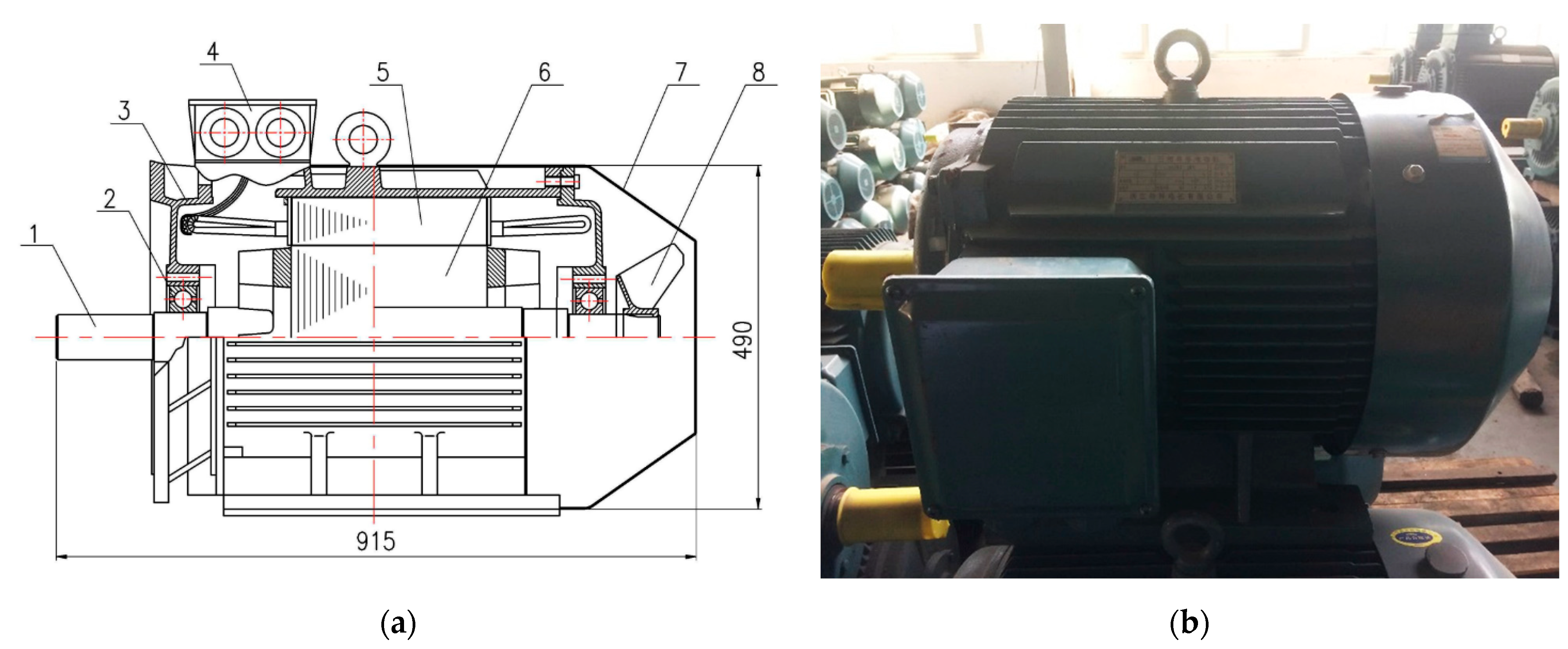
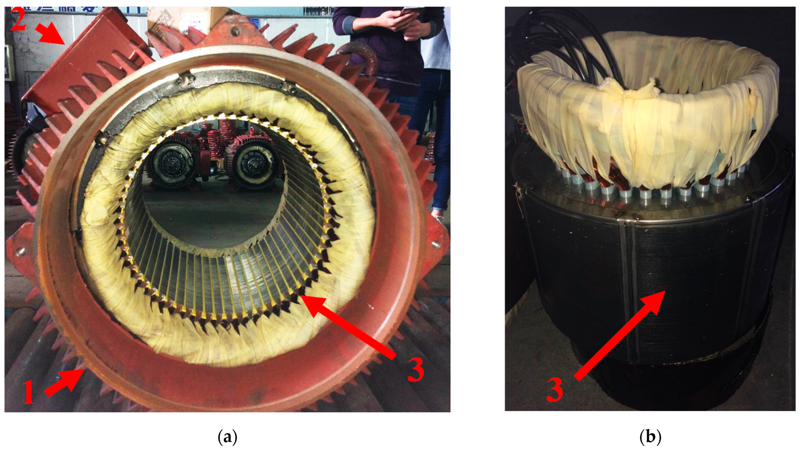
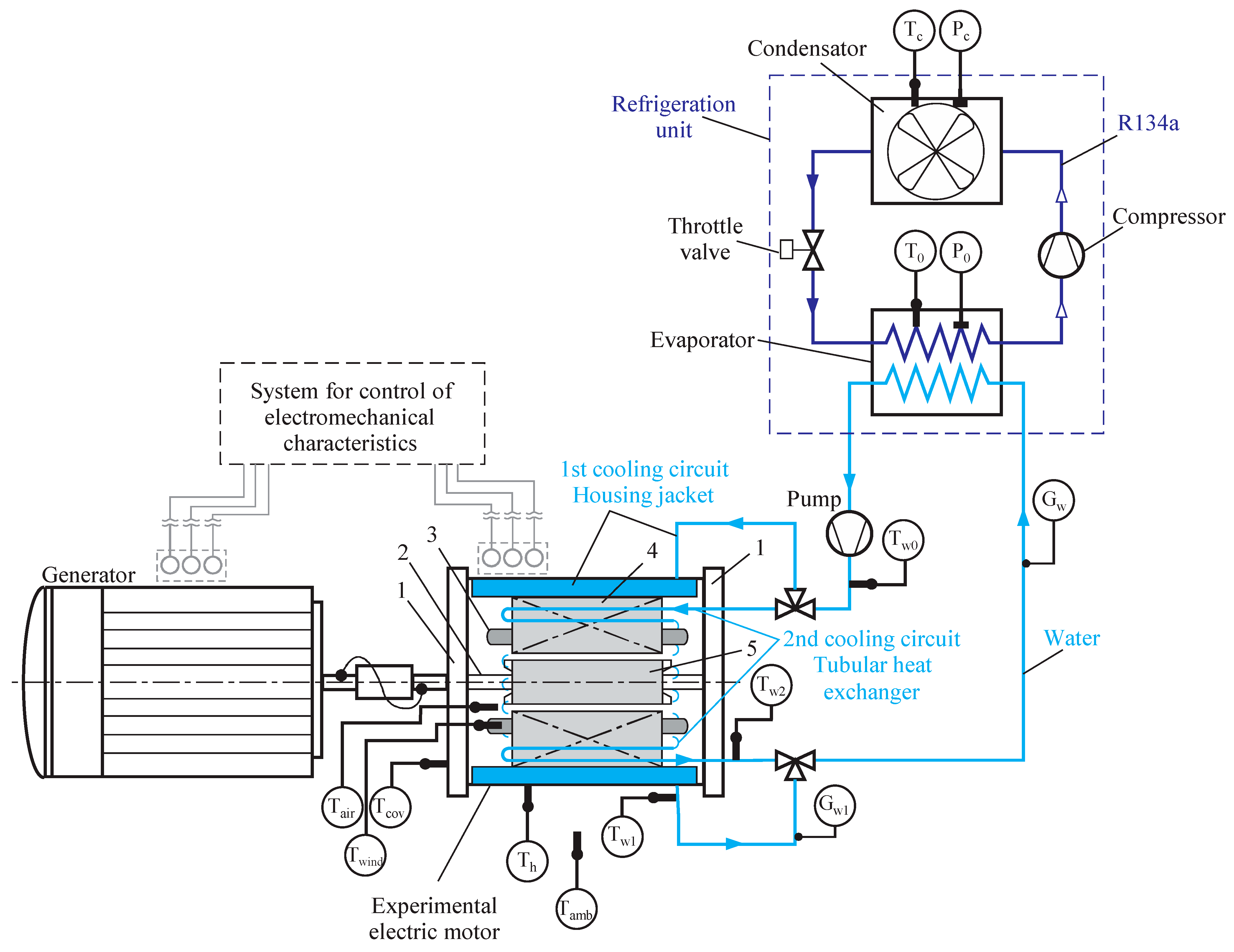


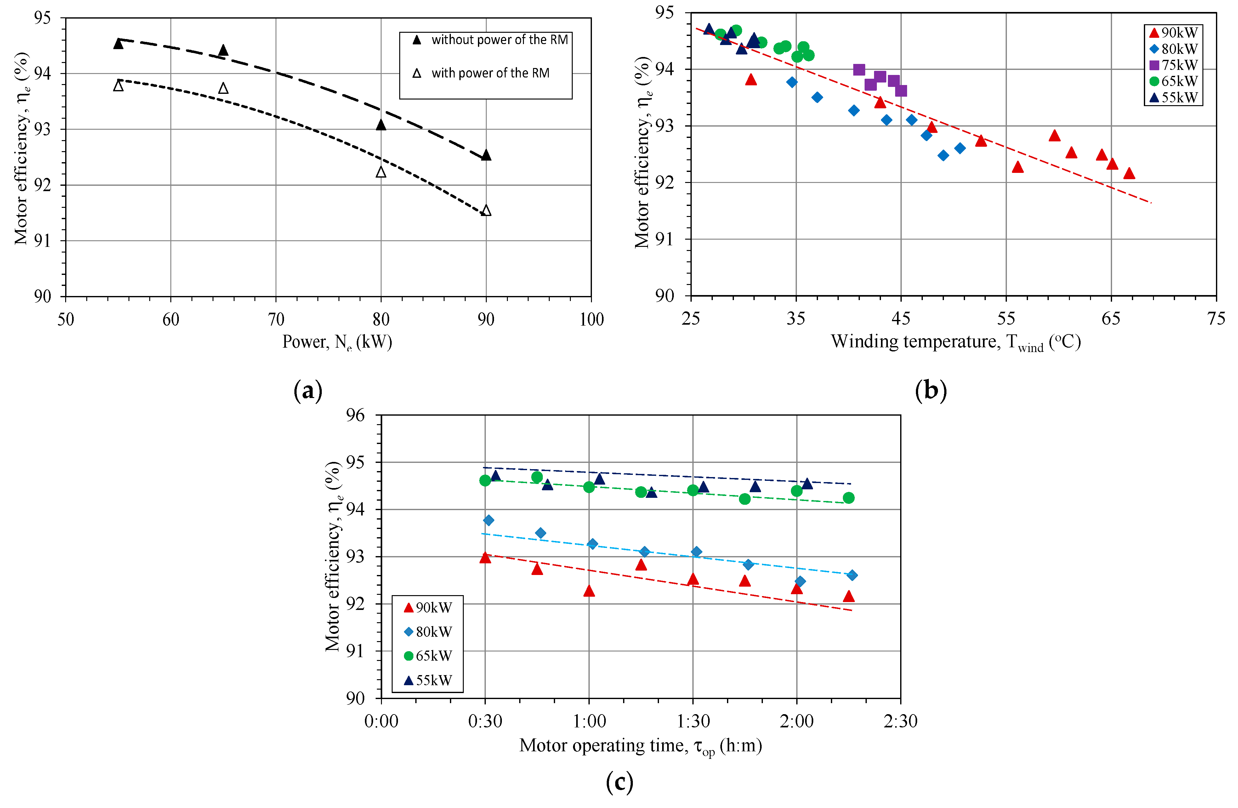
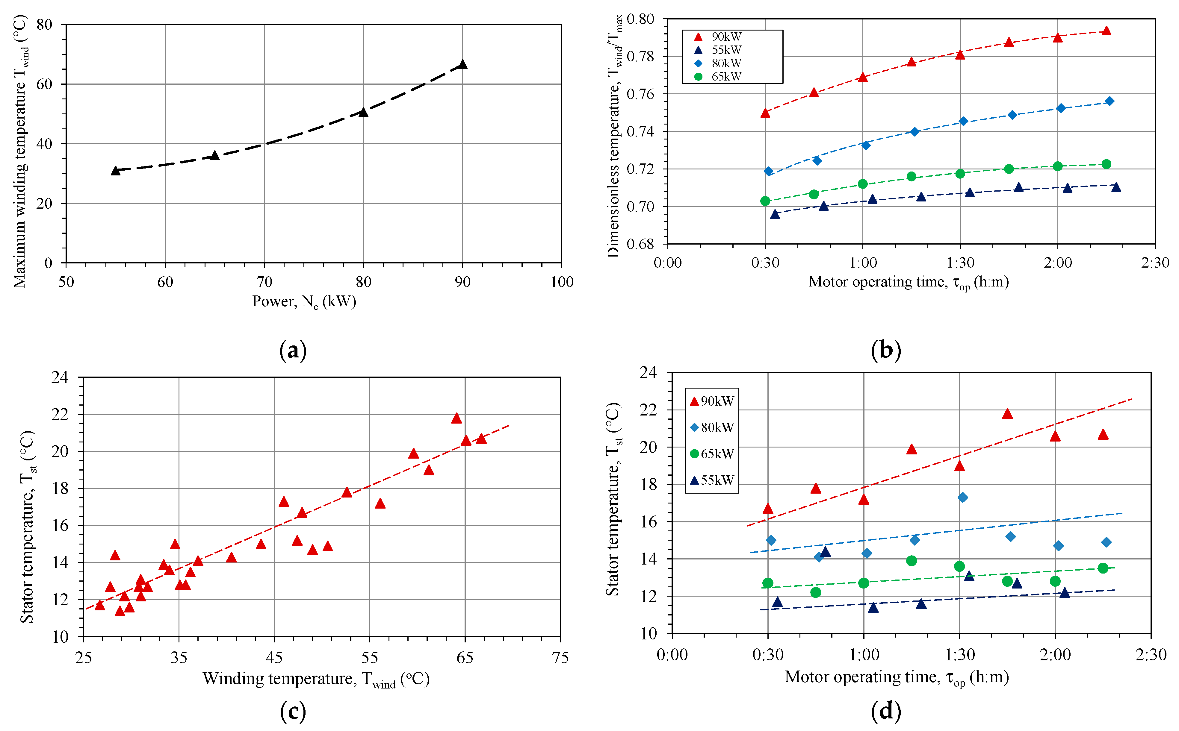
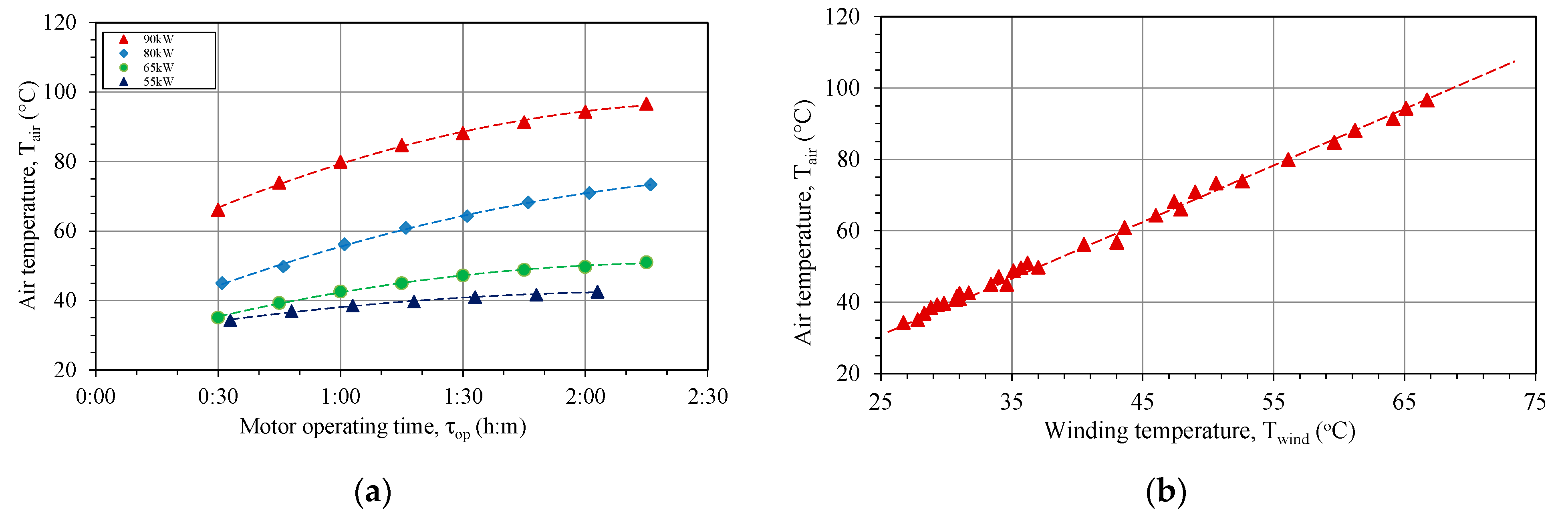
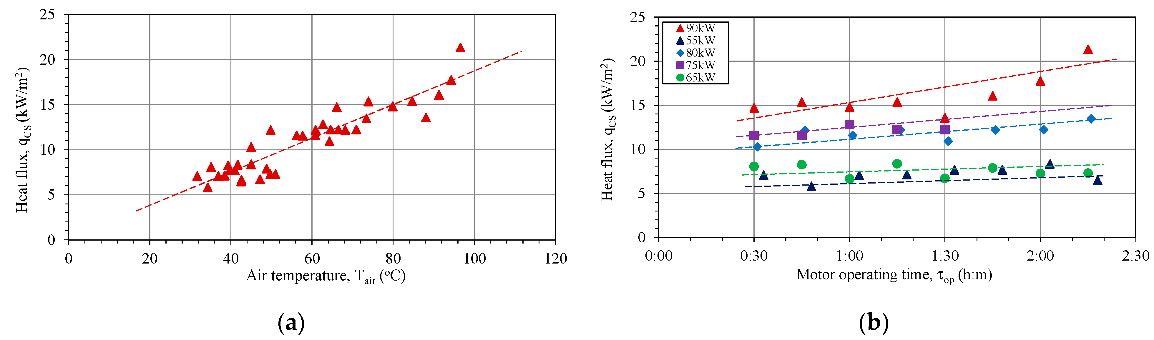
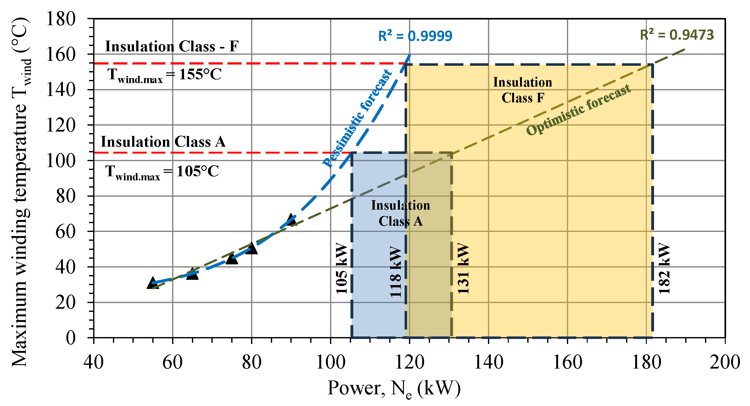

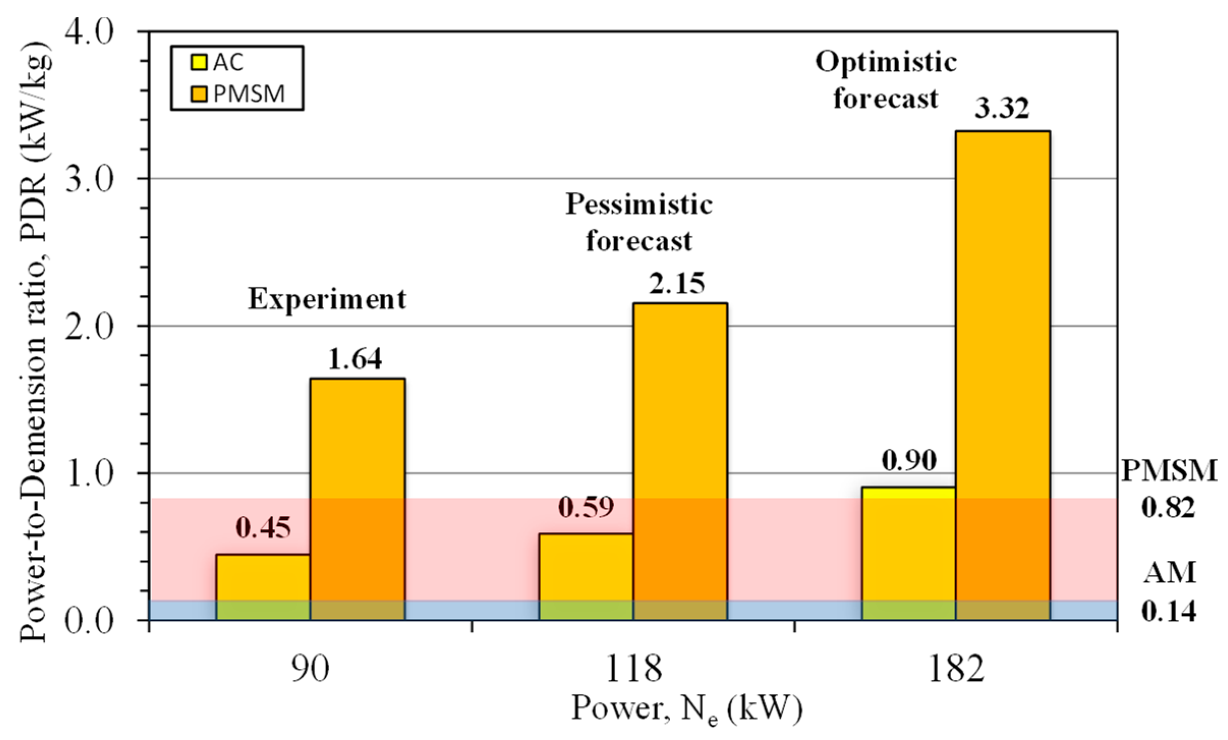
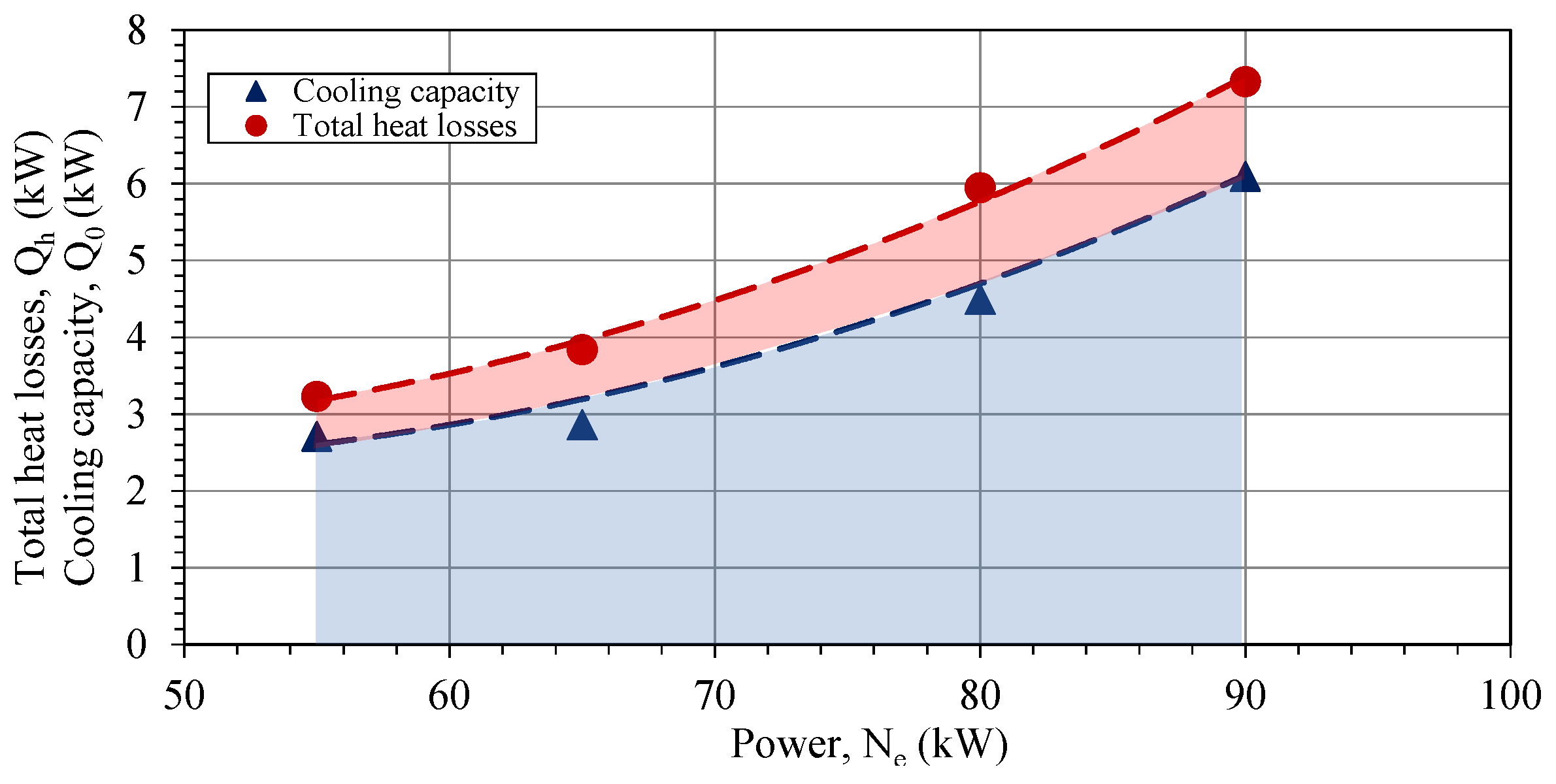
Disclaimer/Publisher’s Note: The statements, opinions and data contained in all publications are solely those of the individual author(s) and contributor(s) and not of MDPI and/or the editor(s). MDPI and/or the editor(s) disclaim responsibility for any injury to people or property resulting from any ideas, methods, instructions or products referred to in the content. |
© 2023 by the authors. Licensee MDPI, Basel, Switzerland. This article is an open access article distributed under the terms and conditions of the Creative Commons Attribution (CC BY) license (https://creativecommons.org/licenses/by/4.0/).