
Frictional Losses of Ring Pack in SI and HCCI Engine


1
Faculty of Mechanical Engineering, Lublin University of Technology, 20-618 Lublin, Poland
2
Faculty of Transport, Warsaw University of Technology, 00-662 Warsaw, Poland
*
Author to whom correspondence should be addressed.
Energies 2023, 16(24), 8096; https://doi.org/10.3390/en16248096
Submission received: 24 November 2023
/
Revised: 12 December 2023
/
Accepted: 14 December 2023
/
Published: 16 December 2023
(This article belongs to the Special Issue Internal Combustion Engine: Research and Application—2nd Edition)
Abstract
:The vast majority of research dedicated to enhancing the homogenous charge compression ignition (HCCI) low-temperature combustion system is focused on improving controllability, efficiency and emissions. This article aims to assess the impact of HCCI combustion on the operation of the piston ring system. Utilizing the measured pressures in the combustion chamber of a single-cylinder research engine operating in spark ignition (SI) and HCCI modes at various loads, simulations were carried out using an advanced ring pack model. This model integrates the gas flow, ring dynamics and ring mixed lubrication models. Simulations revealed that differences in the pressure above the piston between the HCCI and SI combustion significantly influence ring pack performance. The predicted energy losses due to the friction of piston rings against the cylinder liner are up to 5% higher in the HCCI engine than in the SI engine. This identified drawback diminishes the advantages of the HCCI engine resulting from higher thermal efficiency, and efforts should be made to minimize this negative impact.
1. Introduction
The reliable operation of the piston-ring-cylinder (PRC) system is critical for an internal combustion (IC) engine. Investigations into the operation of the piston ring pack have garnered the attention of many scientists due to their significance in determining the mechanical efficiency, wear, fuel economy, and exhaust emissions of an IC engine. The PRC system has a huge share in engine frictional losses—about 30–65% [1,2,3,4,5].
Piston rings can be treated as the most intricate tribological system in the IC engine to analyze due to high variations in load, speed, temperature, and lubricant accessibility. The PRC system may experience hydrodynamic, mixed, and boundary lubrication in one single piston stroke.
In-depth analyses of oil flow in the PRC system were demonstrated by Gulwadi [2], Tian [6], Novotný et al. [7], Koszalka and Guzik [8], Li et al. [9] and Wolff [10,11]. In most publications, one-dimensional models of hydrodynamic ring lubrication were assumed. In such models, the oil gap between the ring and cylinder liner surface was constant around the entire cylinder circumference. To determine the distribution of hydrodynamic pressure in the oil gap, the well-established Reynolds equation was solved, considering appropriate boundary conditions on the inlet and outlet sides of the ring. Different kinds of boundary conditions, such as half Sommerfeld, oil separation and Reynolds cavitation and reformation, were thoroughly analyzed among others by Razavykia et al. [12]. It means that cavitation phenomena in piston ring oil gaps were also investigated. Numerous studies on oil consumption were also conducted, including those by Gulwadi [2]. Bolander et al. [13] developed and discussed a two-dimensional oil flow model, which considers the variability of the oil gap and hydrodynamic pressure around the circumference of the rings.
A lot of scientists analyzed and investigated the mixed lubrication phenomena concerning the PRC system, for example, Bolander et al. [13], Tamminen at al. [14], Soederfjaell et al. [15], Tomanik et al. [16], Chu et al. [17] and Wolff [10,18]. Patir and Cheng’s works [19,20] were of fundamental significance in this area. They proposed modifications to the Reynolds equation to represent the pressure distribution and flow rates between two rough surfaces. In turn, Greenwood and Tripp in their work [21] proposed a model of elastic contact between two rough surfaces. They provided relationships between statistical parameters of roughness and normal and tangential forces of surface interaction.
Many researchers utilized the Greenwood and Tripp model [21] to simulate boundary friction between the rings and the cylinder liner, with the majority adopting a Gaussian roughness distribution. However, this was a gross simplification because the surface texture of the honed cylinder liner features grooves much deeper than the roughness of the surrounding surface. In response to this, Bolander and Sadeghi [22] developed a mixed lubrication model that considers a more realistic surface profile. This profile was numerically generated based on a three-dimensional measurement of the liner profile.
The results of the research on the friction, lubrication and wear of the piston-ring-cylinder system have been published in many other articles, e.g., [23,24,25,26,27,28,29]. An extensive review concerning the theoretical and experimental investigations of rough-surface contact for the prediction of friction in the mixed and boundary lubrication conditions has been presented in [30].
Nowadays, SAE 0W-20 or even lower viscosity oils are often used. When using such oils, the oil film thickness and therefore the contact friction will be greater. In turn, losses due to hydrodynamic friction will be smaller. As a consequence, the shares of contact forces should be higher. Lin et al. [31] conducted experimental investigations to examine the impact of contemporary low-phosphorus engine oils on the friction and wear of a standard car engine cylinder.
Homogeneous charge compression ignition (HCCI) is an advanced engine technology that implements low-temperature combustion. It offers better fuel efficiency and reduced emissions of harmful exhaust gases, especially NOx [32,33,34,35,36]. It also exhibits good compatibility with alternative fuels, including biofuels and synthetic fuels [37,38,39]. These advantages of HCCI can help achieve sustainability goals, and much research is focusing on the practical application of this technology. The biggest challenges and most research are related to controlling ignition timing and extending the operating range [40,41,42]. The pressure course in the combustion chamber of an HCCI engine is different from the pressure course in a spark ignition or a diesel engine. This difference affects the operation of the PRC system, causing greater energy losses related to blow-by and, to some extent, the friction of the piston rings against the cylinder [43]. This study also showed that the contribution of blow-by to the energy losses in the HCCI engine is comparable to the losses associated with ring friction.
This work is a continuation of previous research devoted to assessing the impact of HCCI combustion on the operation of the piston-rings-cylinder system [43]. However, in those studies, a simplified model of ring–cylinder interaction was used, assuming that only fluid friction occurs between the rings and the cylinder liner. In this study, a much more advanced model was used, taking into account mixed friction. The influence of the engine load and combustion system (SI and HCCI) on ring friction against the cylinder and the associated energy losses are analyzed in the article. The analysis is based on simulations using an in-house piston ring pack model. The input data for the simulations were obtained from measurements carried out on a research engine that could operate both as an SI engine and as an HCCI engine.
2. Piston Ring Pack Model
The ring pack model used in this research includes three models: (a) model of gas flow through the ring pack, (b) model of ring dynamics and (c) model of ring lubrication. All these models are integrated. Since all of the above models have been described in detail earlier [8,10], only a brief description is provided below, allowing you to understand their most important assumptions.
2.1. Gas Flow Model
The gas flow model assumes that the gas between the combustion chamber and the crankcase can flow through the ring locks and gaps between the side surfaces of the rings and grooves. The possibility of flow between the front surfaces of the rings and the cylinder liner was not considered. The appropriate diagram is shown in Figure 1. The model takes into account the thermal deformations of the elements and the displacements of the rings in the grooves, which means that all cross-sectional areas of the flows (A in Figure 1) and the volumes of the individual inter-ring and behind-ring spaces (V in Figure 1) are not constant, but change as a function of the crankshaft rotation angle. It was assumed that the flowing gas is a semi-ideal gas whose internal energy . The flow, both through the ring locks (Q1 and Q4 in Figure 1) and through the gaps between the side surfaces of the ring and the groove (Q2, Q3, Q5 and Q6 in Figure 1), is modeled as isentropic—critical or subcritical, depending on the pressure in the space from which the gas flows. Unlike most models described in the literature and used in simulations of piston-rings-cylinder assembly [2,3,6,7], the model used does not assume that the gas temperature in individual volumes is equal to the temperature of the surrounding walls, but the heat transfer between the gas and the walls was calculated (Qwall). Then, the temperature and pressure of the gas in a given stage were calculated from the energy conservation Equation (1) and the gas equation of state (2), taking into account the mass balance of the gas flowing into and out of a given space (3):
where i means enthalpy, the lack of an index means that the quantity refers to a given space and the in and out indexes refer to the quantity flowing into and out of a given space. A more detailed description of the gas flow model can be found in [8].
2.2. Ring Dynamics Model
The axial position of the ring in the groove is determined from the balance of the forces acting on the ring in the axial direction. This balance takes into account the gas forces Fpx, the inertia forces Fix and the friction forces of the ring against the cylinder Fhx and Fcx (Figure 2). If the ring adheres to the groove and the sum of the above forces presses it against the groove wall, then these forces are balanced by the reaction force Rx and the ring moves with the piston speed v. If the resultant of these forces begins to push the ring away from the groove wall, then the axial position of the ring relative to the groove xr is determined from the relationship:
The model assumes that the cylinder, piston and rings are axially symmetrical. Therefore, the radial position of the ring, i.e., its outer diameter, results from the diameter of the cylinder liner at the point of contact with the ring and the thickness of the oil film. The thickness of the oil film is determined from the mass balance of the oil flowing through the gap between the front surface of the ring and the cylinder liner and the balance of the forces acting on the ring in the radial direction (Figure 2):
The hydrodynamic force Fh and elastic contact force Fc, same as the hydrodynamic friction force Fhx and contact friction force Fcx, are determined in the mixed lubrication model described in the next section. Fe is the self-elastic force of the ring. In this article, the values in Formulas (4) and (5) and elsewhere are forces per unit circumference.
2.3. Mixed Lubrication Model
The model assumes that the starved or full lubrications are possible and that the surface of the cylinder liner and the front surface of the ring are rough. Depending on the roughness and the thickness of the oil film, there may be only fluid friction or fluid friction and friction resulting from the elastic contact of rough surfaces, as shown in Figure 3.
A one-dimensional Reynolds equation modified to model the oil flow between rough surfaces by Patir and Cheng [19] was used to calculate the hydrodynamic pressure in the gap between the ring face and the cylinder liner:
where: p—hydrodynamic pressure, x—coordinate along cylinder liner, h—nominal oil film thickness, hT—local oil film thickness, U—axial ring velocity, µ—dynamic oil viscosity, t—time, —composite root mean square roughness of sliding surfaces, —pressure flow factor, and —shear flow factor. The pressure and shear flow factors were calculated from empirical equations given in [20].
The boundary conditions specified in [44] were used to solve Equation (6). They assume that the hydrodynamic pressure at the oil inlet is equal to the gas pressure p1:
and at the oil outlet is equal to the gas pressure p2, and the pressure gradient is equal to zero (Figure 3):
The hydrodynamic force per unit circumference was calculated by the integration of the hydrodynamic pressure distribution:
and the hydrodynamic friction force per unit circumference Fhx was calculated from the equation:
The interactions between the asperities of the piston ring face and cylinder liner were modeled using the model developed by Greenwood and Tripp [21]. The following equation determined the asperity contact force per unit circumference:
and the friction force per unit circumference arising from elastic contact was calculated by the equation:
where the integration limits xl and xr define an interval in which , η—asperity density, E′—composite elastic modulus of mating surfaces, β—combined asperity radius of curvature, and F5/2—empirical function of H, Ac—the real area of contact, τ0—the Eyring shear stress of the oil, and α—the coefficient of asperity shear strength. E′, β, F5/2 and Ac were calculated from the formulas given in [21]. In this calculation, the following values were assumed: τ0 = 2 MPa and α = 0.08.
A computer program integrating all the above models has been developed and applied in this study. The numerical solution of Equation (6) is based on the implicit finite difference scheme [10].
3. Object, Experiment and Simulations
3.1. Research Object
The research object was a single-cylinder, four-stroke research engine, the basic parameters of which are presented in Table 1. This engine was equipped with a timing system allowing for changing the opening and closing phases of the valves and their lift within a very wide range. Thanks to this, the engine could operate as a classic SI engine and as an HCCI engine with NVO. The engine control system was computer-based and provided with dedicated software. It was connected to a timing module that controlled injection timings and durations as well as spark ignition timing.
3.2. Test Stand and Measurements
The engine was mounted on an engine dynamometric bench equipped with appropriate control and measurement systems. The bench equipment allowed for the precise control of engine operating conditions, including the temperature of the coolant and engine oil, as well as measurements of many engine operating parameters. In addition to the basic values always measured on a dynamometric stand, the measurements of the blow-by rate, excess air ratio and pressure in the combustion chamber were important from the point of view of the research conducted. The pressure in the combustion chamber was recorded as a function of the crankshaft angle with a resolution of 0.1 deg. A detailed description of the instruments used in the measurements can be found in [46].
The measurements were carried out at a constant crankshaft speed of 1500 rpm and three different engine loads, from very low to the maximum achievable in the HCCI mode. The plan was to perform measurements at the following loads expressed as the indicated mean effective pressure (IMEP): 0.15 MPa, 0.35 MPa and 0.60 MPa. In the SI mode, the engine operated on a stoichiometric mixture and the load was regulated by opening the throttle. In the HCCI mode, the throttle was fully open and the load was regulated by the injected fuel dose. Valve timing in the HCCI mode was changed with the load. The values of the opening and closing of the intake and exhaust valves (IVO, IVC, EVO and EVC) were determined in previous studies devoted to the low-temperature combustion process [47]. The engine operating conditions together with the valve timing and the maximum lifts of the intake valve (IV lift) and exhaust valve (EV lift) are presented in Table 3. The table shows the actual IMEP values, i.e., calculated for the average of 100 recorded cycles during engine operation at a given load (see Figure 4). The engine bench tests are described in more detail in [43]. SAE 10W-40 grade engine oil was used during the tests.
3.3. Simulations
The key input data for the simulations were the engine dimensions, especially of the elements forming the ring pack, and the pressures in the combustion chamber. The dimensions of the cylinder, piston and rings were determined based on measurements of the cold elements. The thermal deformations determined using the finite element method were added to these dimensions. The roughness parameters used in the simulations are presented in Table 4. The values adopted were previously determined for a car engine with similar dimensions and piston system design [48]. The average pressure from 100 consecutive cycles measured while the engine was operating under set conditions was used in the simulations as the pressure above the piston. The pressures for the tested loads and the engine operating in the SI and HCCI modes are shown in Figure 4.
Simulations were performed for three loads for the engine operating in both the SI and HCCI modes. The input data for the simulation at the assumed load (IMEP = 0.15, 0.35 or 0.60 MPa) for the engine operating in the SI and HCCI modes differed only in the indicated pressure.
4. Results and Discussion
4.1. Pressure in the Combustion Chamber in SI and HCCI Modes
The measurement results presented in Figure 4 show differences in the pressure profile in the combustion chamber for the engine working in the SI and HCCI modes. The first significant difference is the large increase in pressure between the exhaust and intake strokes in an HCCI engine, which does not occur in an SI engine. The incomplete emptying of the combustion chamber of exhaust gases and their recompression is necessary to achieve the self-ignition of the mixture in the HCCI mode. This recompression was achieved by NVO (see Table 3). The second difference is a much faster increase in pressure after auto-ignition occurs and much higher maximum combustion pressures in an HCCI engine. Another difference is the higher pressure during the compression stroke in an HCCI mode, mainly due to the operation with the throttle fully open. These differences in the pressure profiles above the piston affect the operation of the piston assembly and their impact on the mating of piston rings with the cylinder. It will be discussed in detail below.
The impact of the above differences on the blow-by was discussed in detail in [43], which presents the results of the simulations carried out on a model considering only fluid friction. Therefore, unlike the simulations presented in this paper, asperity contact was omitted. However, since the blow-by obtained in the simulations presented here do not differ much from those presented in [43], and considering that blow-by is not the subject of this article, the differences in the gas flow through the ring pack between the SI and HCCI modes will not be discussed here. Suffice it to say that the blow-by rates obtained in the simulations were consistent with the measured ones.
4.2. Top Ring Friction
The total radial force, equal to the sum of the hydrodynamic force and the asperity contact force (Equation (5)), acting on the top ring is quite proportional to the pressure above the piston (Figure 4). When the pressure above the piston is high, the top ring sticks to the lower shelf of the groove, and then the pressure behind the ring is almost equal to the pressure above the ring. The radial force is the sum of the force resulting from this pressure and the self-elastic force (Equation (5)). However, in periods when the pressure behind the ring is high, the force resulting from this pressure is enormous compared to the force of self-elasticity (see Table 3), so the contribution of the latter is negligible. Hence, the radial force is proportional to the pressure in the combustion chamber.
The influence of the load and operating mode on the radial force pressing the top ring to the cylinder liner is considerable (Figure 5). However, these considerable differences have little impact on the total friction force (Figure 6), because this force comes almost entirely from hydrodynamic friction, for which the influence of radial force is small. Moreover, as the engine load increases, the hydrodynamic friction force slightly decreases due to the lower viscosity of the oil. The viscosity is lower because the cylinder liner temperatures are higher at higher loads.
Contact friction occurs only in the narrow ranges of the crankshaft rotation angle around TDC (Figure 7), causing short-term but sudden increases in the total friction force visible in Figure 6, especially for high loads near the TDC after firing.
The contact friction force (Figure 7) increases with the engine load and is much higher in the HCCI mode. In the SI mode, this force occurs only around the TDC after firing, with no contact at the smallest load. In the HCCI mode, this force also appears around the TDC between the exhaust and intake strokes, which is related to the additional compression of the exhaust gases in this mode. However, the values of these forces in this part of the engine cycle are small compared to the forces occurring at the beginning of the power stroke (Figure 7).
The explanation of the above effect of the combustion system and load on ring friction is as follows. The influence of the radial force on the oil film thickness is significant (Figure 8). However, the effect of radial force on ring friction depends on the thickness of the oil film. As long as the film is thick enough and there is only fluid friction, this effect is small. When the minimum oil film thickness drops below the value at which the elastic contact between the asperities of the mating surfaces appears, its effect becomes very significant. This is because in the range of mixed and boundary friction, the share of the hydrodynamic force in the total force balancing the ring pressure on the cylinder decreases, and the elastic contact force increases rapidly as the minimum oil film thickness decreases. These rapid increases account for the reason for the much larger relative difference in the maximum friction forces between the SI and HCCI modes at high loads (Figure 6) compared to the relative difference in radial forces (Figure 5).
4.3. Second Ring Friction
The course of the total radial forces acting on the second ring is similar to the course of the radial forces acting on the top ring, except that the values of these forces are approximately 2.5 times smaller (Figure 9). As in the top ring case, these forces increase with the engine load and are more significant for the HCCI mode.
The surface roughness of the second ring and the cylinder liner in the SI mode come into contact only at the highest analyzed load. However, the friction force associated with it is minimal (Figure 10). In the HCCI mode, contact occurs at both TDC before the power stroke and before the intake stroke at all loads tested. The greater the load, the greater the interactions between the surfaces. The contact friction forces are much higher in the HCCI mode than in the SI mode, but their effect on the total friction force is noticeable only at the highest engine load (Figure 11).
Due to the absence or small values of the contact friction forces, the total friction forces of the second ring against the cylinder are practically equal to the hydrodynamic friction forces. Since the ring pressure force (Figure 9) has little effect on the hydrodynamic friction force, the values of this force for the SI and HCCI modes are similar. The values of hydrodynamic friction forces, and therefore total friction forces, slightly decrease with the increasing engine load due to higher cylinder temperatures, and therefore lower oil viscosities at higher loads (Figure 11).
The relative speed between the ring and the cylinder has the greatest influence on the oil film thickness between them. The smallest oil film thicknesses occur slightly after the reversion of the crankshaft angle due to the oil squeeze effect. Additionally, the viscosity of the oil and the force pressing the ring to the cylinder have a significant impact. As a result, the minimum oil film thickness decreases with the engine load and is slightly smaller in the HCCI mode than in the SI mode (Figure 12).
4.4. Oil Ring Friction
Since the pressure behind the oil ring is equal to the pressure in the crankcase, the radial force acting on this ring is practically constant and equal to the ring’s elastic force. In the simulations, it was assumed that the cylinder temperatures at a given engine load were the same in the SI and HCCI modes. Consequently, the hydrodynamic and contact friction forces and the sum of these forces in the case of the oil ring are the same for the SI and HCCI modes. The minimum oil film thicknesses are also the same. Therefore, only the results for the SI mode are presented in Figure 13 and Figure 14.
Similarly to the top and second rings, the hydrodynamic force decreases with the engine load, because the cylinder temperature is higher and the oil viscosity is lower. However, the values of this force are approximately twice as small as for the top and second rings. It is related to the smaller height of the oil ring (Table 2). Figure 13 and Figure 14 show the sums of forces for the two lips of the oil ring.
4.5. Energy Losess Due to Ring Friction
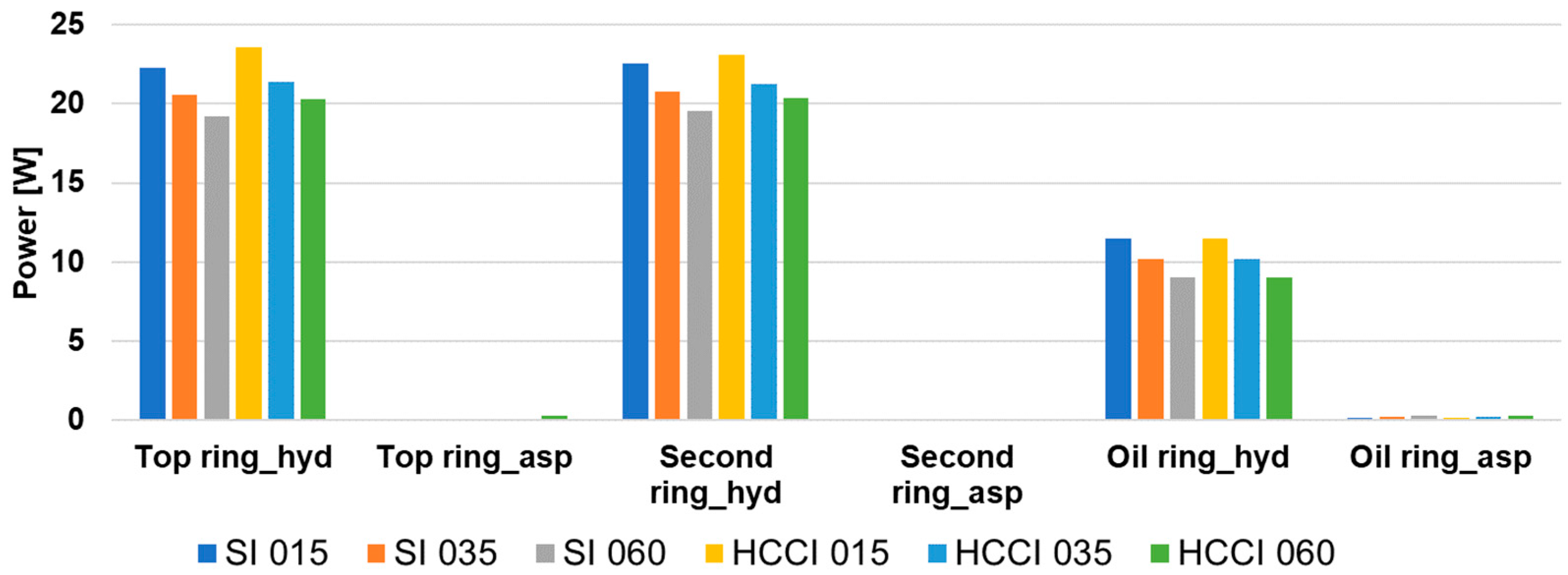
Figure 15 shows the hydrodynamic and contact friction power losses of individual rings at low, medium and high loads of the engine operating in the SI and HCCI modes. Like forces, hydrodynamic friction power losses also decrease with the engine load. For the top and second rings and both operating modes, an increase in load from the lowest to medium causes a decrease in hydrodynamic friction power loss by approximately 9%, and an increase in load from medium to high causes a decrease in power loss by approximately 6%. These changes in the case of the oil ring are larger and amount to 13% and 13%, respectively.
The contact friction power losses of compression rings are equal to zero or are very small compared to the hydrodynamic friction powers. This is also the case of the oil ring, where the maximum values of the contact friction forces are larger than the maximum values of the hydrodynamic friction force (Figure 13). This is due to the very low ring velocities around TDC, where the contact forces reach high values. As the load increases, the contact friction power losses increase. In the case of the oil ring, the load increasing from the lowest to the highest results in a twofold increase in this power. The highest share of contact friction in the total friction power loss occurs in the case of the oil ring at a high engine load and amounts to 3%. For the entire ring pack, the share of contact friction in the total friction power loss is the highest for the engine operating at a high load in the HCCI mode, which slightly exceeds 1%. Although the share of losses related to contact friction is small, the forces of this friction are much more significant in an engine operating at the HCCI mode. This may contribute to the increased wear intensity of the rings and cylinder liner in such an engine.
The most considerable differences in the friction powers between the SI and HCCI modes occur in the case of the top ring—the powers in the HCCI mode are on average about 5.5% higher. In the case of the second ring, they are larger by approximately 3%. As previously mentioned, there are no differences in the case of the oil ring. Compared to the SI engine, the friction losses of the entire ring pack in the HCCI engine are higher by 3.7%, 2.6% and 4.6% at low, medium and high loads, respectively. Therefore, the effect of the operating mode on the energy losses associated with ring friction is significant.
It should be emphasized, however, that the rings in the tested research engine were quite high and that engine oil with a relatively high viscosity was used (SAE 10W-40). The latest designs often use smaller ring heights and lower viscosity oils (SAE 0W-20 or even lower viscosity) to reduce friction losses. When using such rings and oils, the minimum oil film thickness will be smaller, and contact friction losses may be greater. In turn, losses due to hydrodynamic friction will be smaller. Consequently, the shares of contact friction losses will probably be higher than in the tested engine, and the differences between the SI and HCCI modes would be more considerable.
5. Conclusions and Future Works
The article analyzes the impact of low-temperature HCCI combustion on the interaction of piston rings with the cylinder and the associated energy losses. This impact was assessed by a comparison with the losses occurring in an SI engine. The research was carried out on an advanced mathematical model of the ring pack, which considered the roughness of the sliding surfaces of piston rings and cylinder liner and the possibility of mixed friction. The input data for the calculations came from measurements carried out on an engine that could operate as an SI and HCCI engine, which guaranteed that both operating modes had the same piston system. The bench tests of the engine and the corresponding simulation tests were carried out at various loads, from very low to the highest achievable by the tested engine in the HCCI mode.
The main result of the work carried out is the demonstration that the energy losses caused by the friction of the rings on the cylinder in the tested engine operating in the HCCI mode were up to 5% higher than in the same engine operating in the SI mode. This means that the benefits of the greater thermal efficiency of an HCCI engine are partially reduced due to its lower mechanical efficiency.
Additionally, simulations have shown that the radial forces pressing the compression rings against the liner are much more significant when the engine operates in the HCCI mode. This causes the minimum oil film thickness in the HCCI mode to be smaller. In turn, it leads to more frequent asperity contacts of mating surfaces and greater contact friction forces. However, this did not translate into a proportionally large increase in friction losses, because in the tested engine, the losses related to hydrodynamic friction dominated, and the hydrodynamic friction depended to a much lesser extent on the radial force. The shares of contact friction in the total friction losses in the tested engine were minimal—only up to 1%.
The tests were carried out on an engine with relatively high compression rings, and high viscosity engine oil was used. The authors plan to conduct research on the impact of HCCI combustion on the piston ring performance for rings of smaller height and for oil with lower viscosity, as commonly used in the newest engines. We also intend to try to find a solution that would minimize the disadvantage of the HCCI engine with NVO revealed in this research.
Author Contributions
Conceptualization, G.K.; methodology, G.K. and A.W.; software, A.W.; validation, G.K.; formal analysis, G.K. and A.W.; investigation, G.K. and A.W.; resources, G.K.; data curation, G.K. and A.W.; writing—original draft preparation, G.K. and A.W.; writing—review and editing, G.K. and A.W.; visualization, G.K. and A.W.; supervision, G.K. All authors have read and agreed to the published version of the manuscript.
Funding
This research received no external funding.
Data Availability Statement
Data are contained within the article.
Acknowledgments
The authors of this article wish to thank Jacek Hunicz for providing data on the HCCI engine and valuable tips during the research. The authors would also like to thank AVL List GmbH for making the simulation software available within the framework of the AVL University Partnership Program—the software was used to calculate the temperature in the combustion chamber.
Conflicts of Interest
The authors declare no conflict of interest.
References
- Richardson, D.E. Review of power cylinder friction for diesel engines. J. Eng. Gas. Turb. Power 2000, 122, 506–519. [Google Scholar] [CrossRef]
- Gulwadi, S.D. Analysis of Tribological Performance of a Piston Ring Pack. Tribol. Trans. 2000, 43, 151–162. [Google Scholar] [CrossRef]
- Ma, Z.; Henein, N.A.; Bryzik, W. A Model for Wear and Friction in Cylinder Liners and Piston Rings. Tribol. Trans. 2006, 49, 315–327. [Google Scholar] [CrossRef]
- Livanos, G.A.; Kyrtatos, N.P. Friction model of a marine diesel engine piston assembly. Tribol. Int. 2007, 40, 1441–1453. [Google Scholar] [CrossRef]
- Tormos, B.; Martín, J.; Pla, B.; Jimenez-Reyes, A.J. A methodology to estimate mechanical losses and its distribution during a real driving cycle. Tribol. Int. 2020, 145, 106208. [Google Scholar] [CrossRef]
- Tian, T. Dynamic Behaviors of Piston Rings and Their Practical Impact—Part II: Oil Transport, Friction, and Wear of Ring/Liner Interface and the Effects of Piston and Ring Dynamics. Proc. Inst. Mech. Eng. Part J J. Eng. Tribol. 2002, 216, 229–247. [Google Scholar] [CrossRef]
- Novotny, P.; Pistek, V.; Drapal, L.; Svida, D.; Devera, T. Efficient approach for solution of the mechanical losses of the piston ring pack. Proc. Inst. Mech. Eng. Part D J. Automob. Eng. 2013, 227, 1377–1388. [Google Scholar] [CrossRef]
- Koszalka, G.; Guzik, M. Mathematical model of piston ring sealing in combustion engine. Pol. Marit. Res. 2014, 21, 66–78. [Google Scholar] [CrossRef]
- Li, G.; Gu, F.; Wang, T.; Lu, X.; Zhang, L.; Zhang, C.; Ball, A. An Improved Lubrication Model between Piston Rings and Cylinder Liners with Consideration of Liner Dynamic Deformations. Energies 2017, 10, 2122. [Google Scholar] [CrossRef]
- Wolff, A. Simulation based study of the system piston-ring-cylinder of a marine two-stroke engine. Tribol. Trans. 2014, 57, 653–667. [Google Scholar] [CrossRef]
- Wolff, A. Influence of piston ring profiles and oil temperature distribution on cylinder liner lubrication of a marine two-stroke engine. Combust. Engines 2019, 178, 257–263. [Google Scholar] [CrossRef]
- Razavykia, A.; Delprete, C.; Brusa, E.; Hosseini, Y. The Effects of Oil Film Shape on Piston Ring and Liner Tribology under Mixed Lubrication. Am. J. Eng. Appl. Sci. 2021, 14, 436–447. [Google Scholar] [CrossRef]
- Bolander, N.W.; Steenwyk, B.D.; Sadeghi, F.; Gerber, G.R. Lubrication Regime Transitions at the Piston Ring—Cylinder Liner Interface. Proc. Inst. Mech. Eng. Part J J. Eng. Tribol. 2005, 219, 19–31. [Google Scholar] [CrossRef]
- Tamminen, J.; Sandström, C.-E.; Andersson, P. Influence of load on the tribological conditions in piston ring and cylinder liner contacts in a medium-speed diesel engine. Tribol. Int. 2006, 39, 1643–1652. [Google Scholar] [CrossRef]
- Soederfjaell, M.; Herbst, H.M.; Larsson, R.; Almqvist, A. Influence on friction from piston ring design, cylinder liner roughness and lubricant properties. Tribol. Int. 2017, 116, 272–284. [Google Scholar] [CrossRef]
- Tomanik, E.; Mansori, M.E.; Souza, R.; Profito, F. Effect of waviness and roughness on cylinder liner friction. Tribol. Int. 2018, 120, 547–555. [Google Scholar] [CrossRef]
- Chu, N.R.; Jackson, R.L.; Ghaednia, H.; Gangopadhyay, A. A Mixed Lubrication Model of Piston Rings on Cylinder Liner Contacts Considering Temperature-Dependent Shear Thinning and Elastic–Plastic Contact. Lubricants 2023, 11, 208. [Google Scholar] [CrossRef]
- Wolff, A. Numerical Analysis of the System Piston-Ring-Cylinder of an Automotive IC Engine. In Proceedings of the SAE Powertrains, Fuels & Lubricants Meeting, Kraków, Poland, 22–24 September 2020. [Google Scholar] [CrossRef]
- Patir, N.; Cheng, H.S. An Average Flow Model for Determining Effects of Three-Dimensional Roughness on Partial Hydrodynamic Lubrication. J. Lubr. Tech. 1978, 100, 12–17. [Google Scholar] [CrossRef]
- Patir, N.; Cheng, H.S. Application of Average Flow Model to Lubrication Between Rough Sliding Surfaces. J. Lubr. Tech. 1979, 101, 220–229. [Google Scholar] [CrossRef]
- Greenwood, J.; Tripp, J.H. The contact of Two Nominally Flat Rough Surfaces. Proc. Inst. Mech. Eng. 1971, 185, 625–633. [Google Scholar] [CrossRef]
- Bolander, N.W.; Sadeghi, F. Deterministic Modeling of Honed Cylinder Liner Friction. Tribol. Trans. 2007, 50, 248–256. [Google Scholar] [CrossRef]
- Koszalka, G. Predicting the durability of the piston-rings-cylinder assembly of a diesel engine using a piston ring pack model. Eksploat. I Niezawodn. Maint. Reliab. 2011, 51, 40–44. [Google Scholar]
- Vlădescu, S.-C.; Medina, S.; Olver, A.V.; Pegg, I.G.; Reddyhoff, T. Lubricant film thickness and friction force measurements in a laser surface textured reciprocating line contact simulating the piston ring-liner pairing. Tribol. Int. 2016, 98, 317–329. [Google Scholar] [CrossRef]
- Gu, C.; Wang, R.; Tian, T. Modeling the Fatigue Wear of the Cylinder Liner in Internal Combustion Engines during the Break-In Period and Its Impact on Piston Ring Lubrication. Lubricants 2019, 7, 89. [Google Scholar] [CrossRef]
- Li, W.; Yu, B.; Lv, Y.; Shen, Y.; Huang, R.; Du, F. Wear Behavior of CuSn Coated Piston Ring Sliding against Nodular Cast Iron Cylinder Liner under Heavy-Duty Conditions. Metals 2019, 9, 139. [Google Scholar] [CrossRef]
- Koszalka, G.; Krzeczek, P. Energy Losses Related to Ring Pack Wear in Gasoline Car Engine. Energies 2022, 15, 9570. [Google Scholar] [CrossRef]
- Tomanik, E.; Christinelli, W.; Souza, R.M.; Oliveira, V.L.; Ferreira, F.; Zhmud, B. Review of Graphene-Based Materials for Tribological Engineering Applications. Energies 2023, 4, 2764–2811. [Google Scholar] [CrossRef]
- Li, M.; Zhong, X.; Ahling, S.; Tian, T. An Investigation of Oil Supply Mechanisms to the Top of the Liner in Internal Combustion Engines. In Proceedings of the 2023 JSAE/SAE Powertrains, Energy and Lubricants International Meeting, Kyoto, Japan, 29 August–1 September 2023. [Google Scholar] [CrossRef]
- Taylor, R.I. Rough Surface Contact Modelling—A Review. Lubricants 2022, 10, 98. [Google Scholar] [CrossRef]
- Lin, P.; Barber, G.; Zou, Q.; Anderson, A.H.; Tung, S.; Quintana, A. Friction and Wear of Low-Phosphorus Engine Oils with Additional Molybdenum and Boron Compounds, Measured on a Reciprocating Lubricant Tester. Tribol. Trans. 2008, 51, 659–672. [Google Scholar] [CrossRef]
- Agarwal, A.K.; Singh, A.P.; Maurya, R.K. Evolution, challenges and path forward for low temperature combustion engines. Prog. Energy Comb. 2017, 61, 1–56. [Google Scholar] [CrossRef]
- Zhang, Y.; Zhao, H. Investigation of combustion, performance and emission characteristics of 2-stroke and 4-stroke spark ignition and CAI/HCCI operations in a DI gasoline. Appl. Energy 2014, 130, 244–255. [Google Scholar] [CrossRef]
- Hunicz, J.; Krzaczek, P. Detailed speciation of emissions from low-temperature combustion in a gasoline HCCI engine. Pol. J. Environ. Stud. 2016, 25, 137–145. [Google Scholar] [CrossRef] [PubMed]
- Chauhan, B.V.S.; Sayyed, I.; Vedrantam, A.; Garg, A.; Bharti, S.; Shukla, M. State of the Art in Low-Temperature Combustion Technologies: HCCI, PCCI, and RCCI. In Advanced Combustion for Sustainable Transport. Energy, Environment, and Sustainability; Agarwal, A.K., Martínez, A.G., Kalwar, A., Valera, H., Eds.; Springer: Singapore, 2022. [Google Scholar] [CrossRef]
- Kontarakis, G.; Collings, N.; Ma, T. Demonstration of HCCI using a single cylinder four-stroke SI engine with modified valve timing. SAE Tech. Pap. 2000, 109, 2057–2067. [Google Scholar] [CrossRef]
- Pachiannan, T.; Zhong, W.; Rajkumar, S.; He, Z.; Leng, X.; Wang, Q. A literature review of fuel effects on performance and emission characteristics of low-temperature combustion strategies. Appl. Energy 2019, 251, 113380. [Google Scholar] [CrossRef]
- Kale, A.V.; Krishnasamy, A. Experimental study on combustion, performance, and emission characteristics of a homogeneous charge compression ignition engine fuelled with multiple biofuel-gasoline blends. Energy 2023, 288, 129621. [Google Scholar] [CrossRef]
- Quintana, S.H.; Morales Rojas, A.D.; Bedoya, I.D. Experimental and Numerical Evaluation of an HCCI Engine Fueled with Biogas for Power Generation under Sub-Atmospheric Conditions. Energies 2023, 16, 6267. [Google Scholar] [CrossRef]
- Vasudev, A.; Mikulski, M.; Balakrishnan, P.R.; Storm, X.; Hunicz, J. Thermo-kinetic multi-zone modelling of low temperature combustion engines. Prog. Energy Comb. 2022, 91, 100998. [Google Scholar] [CrossRef]
- Han, L.; Duan, J.; Qian, D.; Gong, Y.; Wang, Y.; Xie, F.; Su, Y. Research on Homogeneous Charge Compression Ignition Combustion of Intake Port Exhaust Gas Recirculation Based on Cam Drive Hydraulic Variable Valve Actuation Mechanism. Energies 2022, 15, 438. [Google Scholar] [CrossRef]
- Hunicz, J.; Gęca, M.S.; Ratajczyk, E.; Andwari, A.M.; Yang, L.; Mikulski, M. An analytical approach to converting vibration signal to combustion characteristics of homogeneous charge compression ignition engines. Energ. Convers. Manag. 2023, 294, 117564. [Google Scholar] [CrossRef]
- Koszałka, G.; Hunicz, J. Comparative study of energy losses related to the ring pack operation in homogeneous charge compression ignition and spark ignition combustion. Energy 2021, 235, 121388. [Google Scholar] [CrossRef]
- Richardson, D.E.; Borman, G.L. Theoretical and Experimental Investigations of Oil Films for Application to Piston Ring Lubrication. In Proceedings of the International Fuels & Lubricants Meeting & Exposition, San Francisco, CA, USA, 19–22 October 1992. [Google Scholar] [CrossRef]
- Hunicz, J. An experimental study of combustion phasing control in CAI gasoline engine with in-cylinder fuel reforming. In Proceedings of the 10th International Conference on Engines & Vehicles, Napoli, Italy, 11–15 September 2011. [Google Scholar] [CrossRef]
- Hunicz, J.; Medina, A. Experimental study on detailed emissions speciation of an HCCI engine equipped with a three-way catalytic converter. Energy 2016, 117, 388–397. [Google Scholar] [CrossRef]
- Hunicz, J.; Mikulski, M.; Geca, M.S.; Rybak, A. An applicable approach to mitigate pressure rise rate in an HCCI engine with negative valve overlap. Appl. Energy 2020, 257, 114018. [Google Scholar] [CrossRef]
- Wolff, A.; Koszałka, G. Influence of engine load on piston ring pack operation of an automotive IC engine. Combust. Engines 2022, 190, 88–94. [Google Scholar] [CrossRef]
Figure 1.
Scheme of the ring pack and corresponding volume and orifice model.
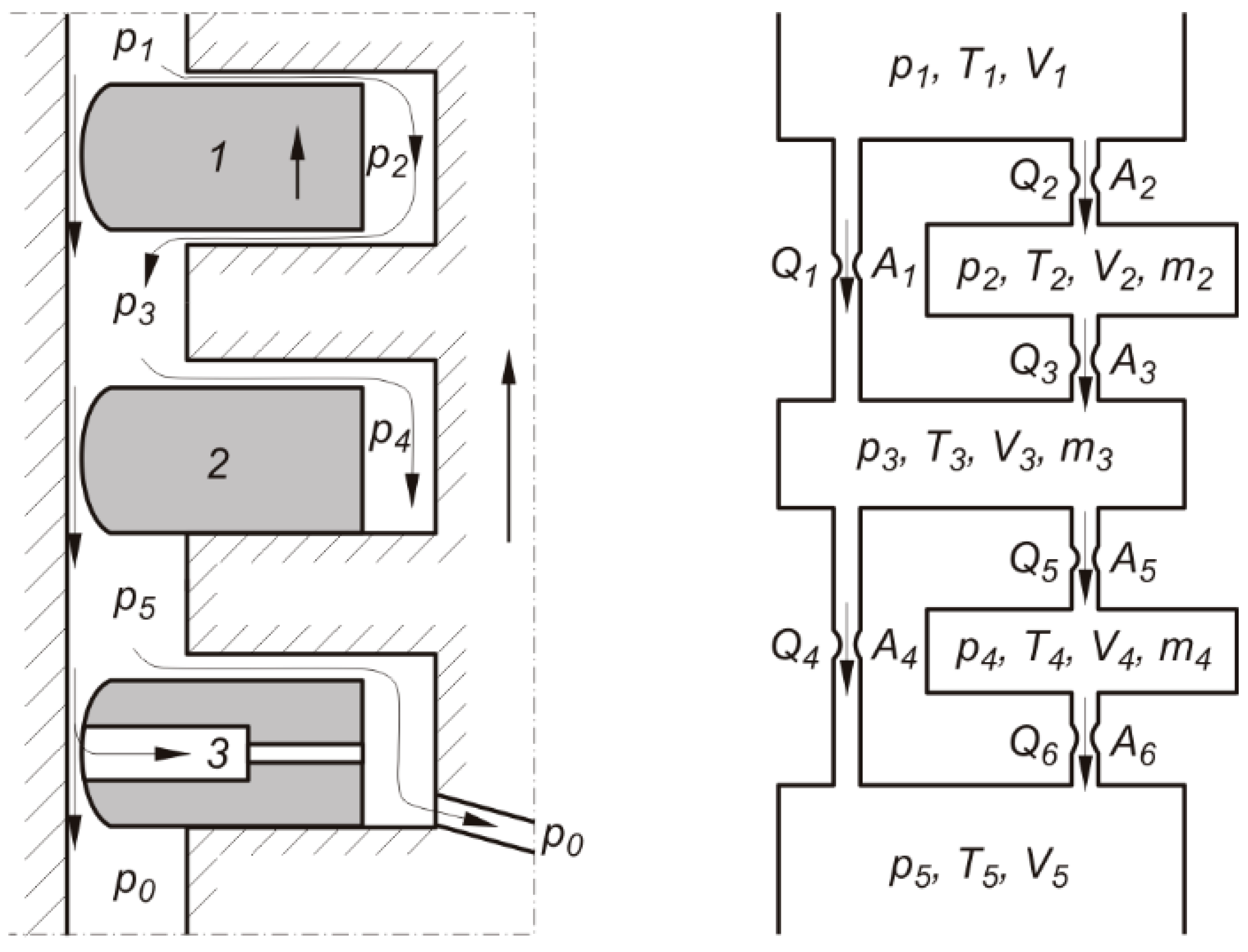
Figure 2.
Pressures and forces acting on the ring (subscripts at pressure as for the first ring).

Figure 3.
Oil and pressure distribution in the gap between the ring face and cylinder liner in the case of: (a) pure hydrodynamic and (b) mixed friction.
Figure 3.
Oil and pressure distribution in the gap between the ring face and cylinder liner in the case of: (a) pure hydrodynamic and (b) mixed friction.
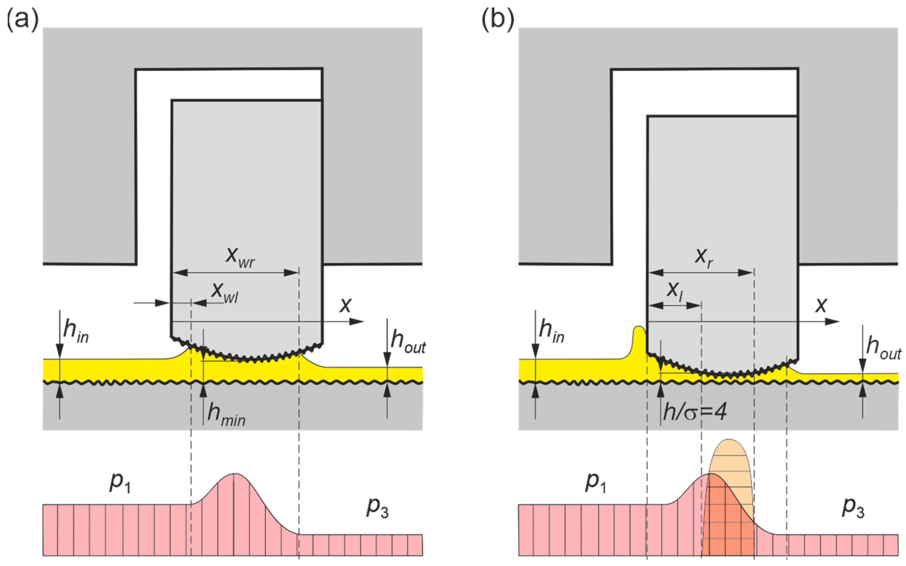
Figure 4.
Pressure in the combustion chamber in SI and HCCI modes at various loads.
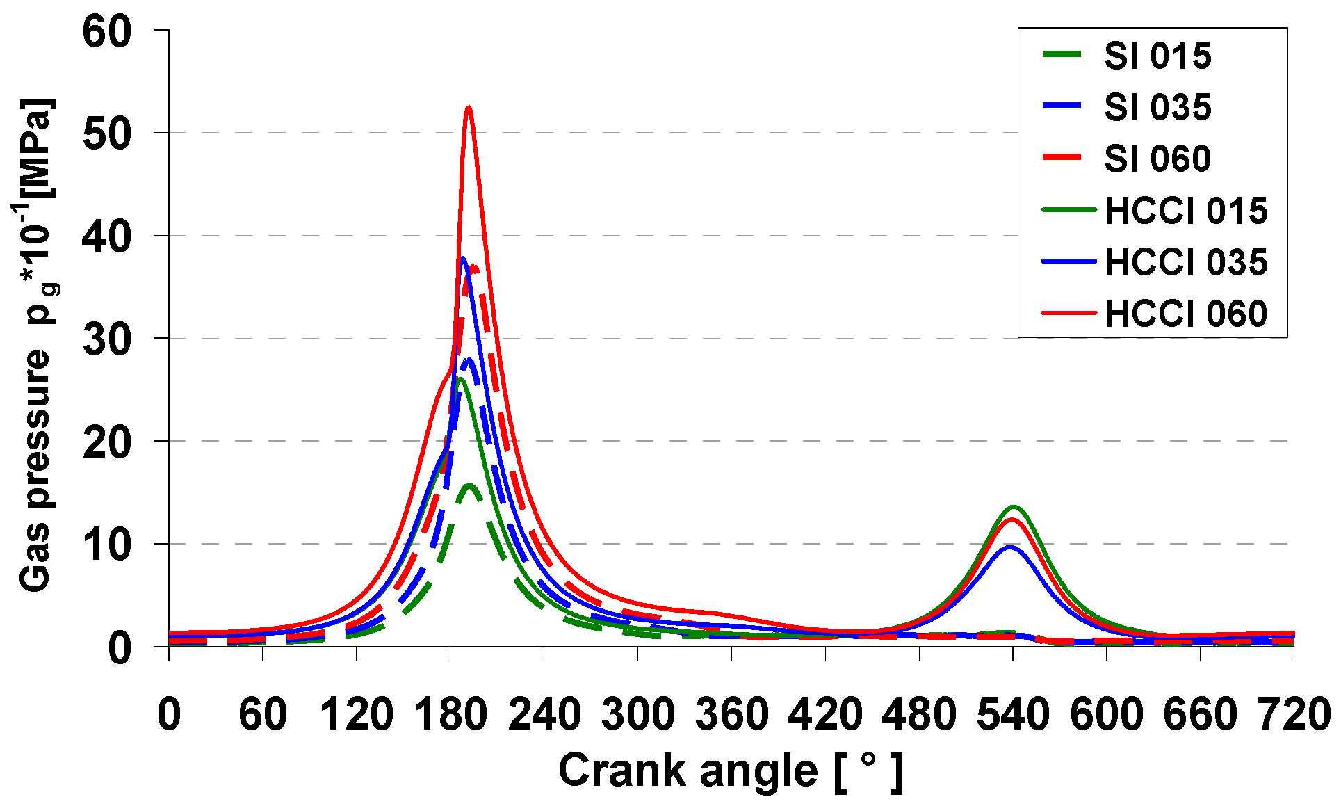
Figure 5.
Total radial unit force of the top ring versus crank angle for (a) SI mode and (b) HCCI mode.
Figure 5.
Total radial unit force of the top ring versus crank angle for (a) SI mode and (b) HCCI mode.
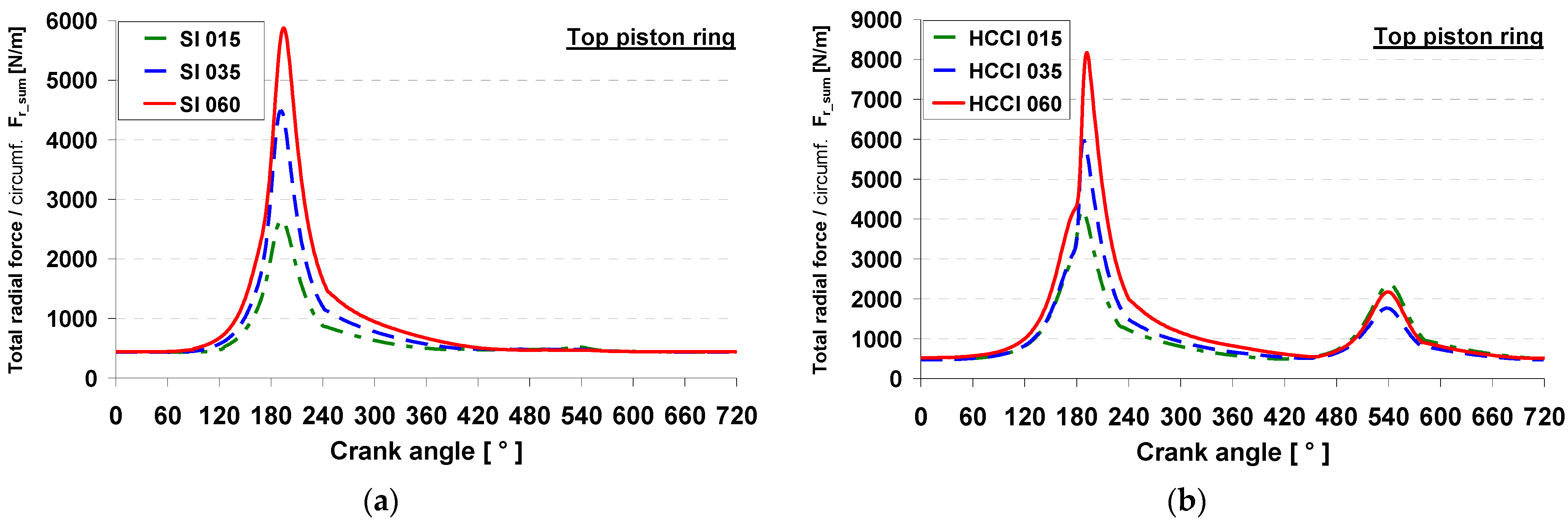
Figure 6.
Total friction unit force of the top ring versus crank angle for (a) SI mode and (b) HCCI mode.
Figure 6.
Total friction unit force of the top ring versus crank angle for (a) SI mode and (b) HCCI mode.
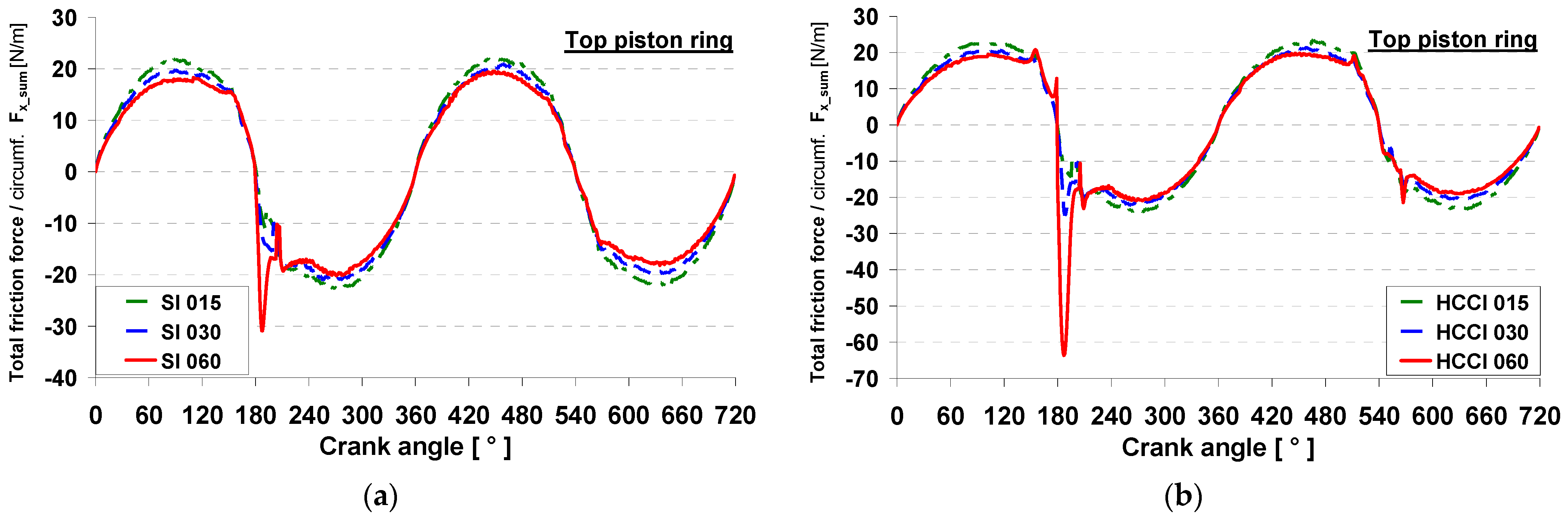
Figure 7.
Contact friction unit force of the top ring versus crank angle for (a) SI mode and (b) HCCI mode.
Figure 7.
Contact friction unit force of the top ring versus crank angle for (a) SI mode and (b) HCCI mode.
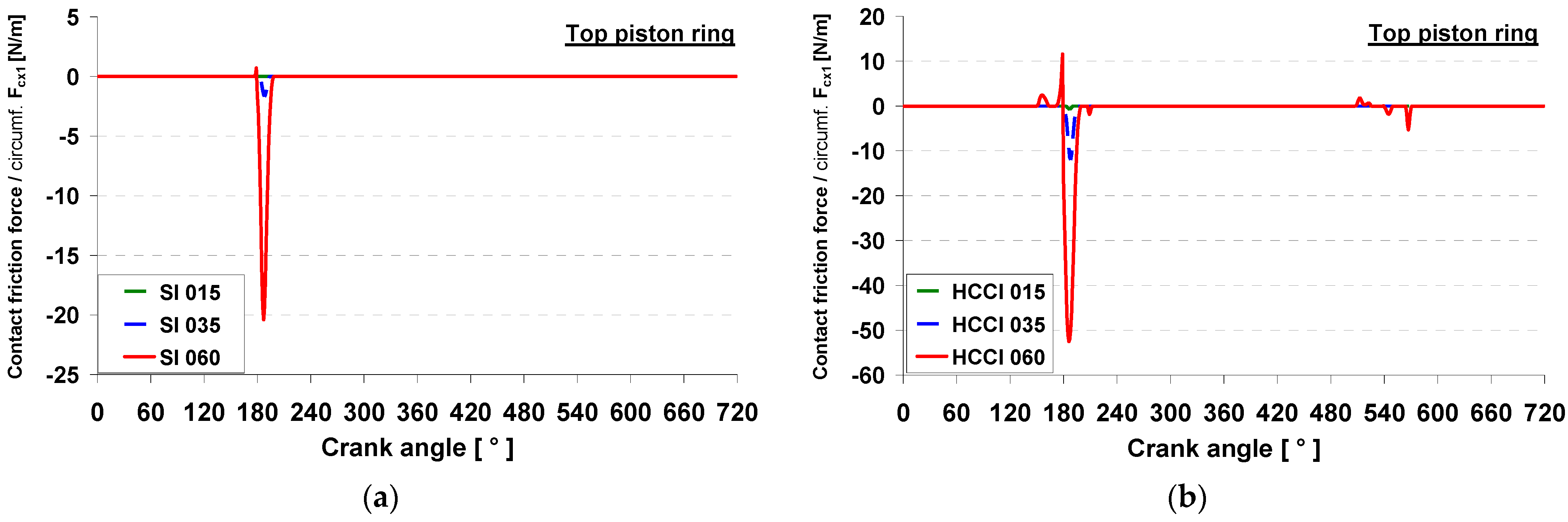
Figure 8.
Minimum oil film thickness of the top ring versus crank angle for (a) SI mode and (b) HCCI mode.
Figure 8.
Minimum oil film thickness of the top ring versus crank angle for (a) SI mode and (b) HCCI mode.

Figure 9.
Total radial unit force of the second ring versus crank angle for (a) SI mode and (b) HCCI mode.
Figure 9.
Total radial unit force of the second ring versus crank angle for (a) SI mode and (b) HCCI mode.
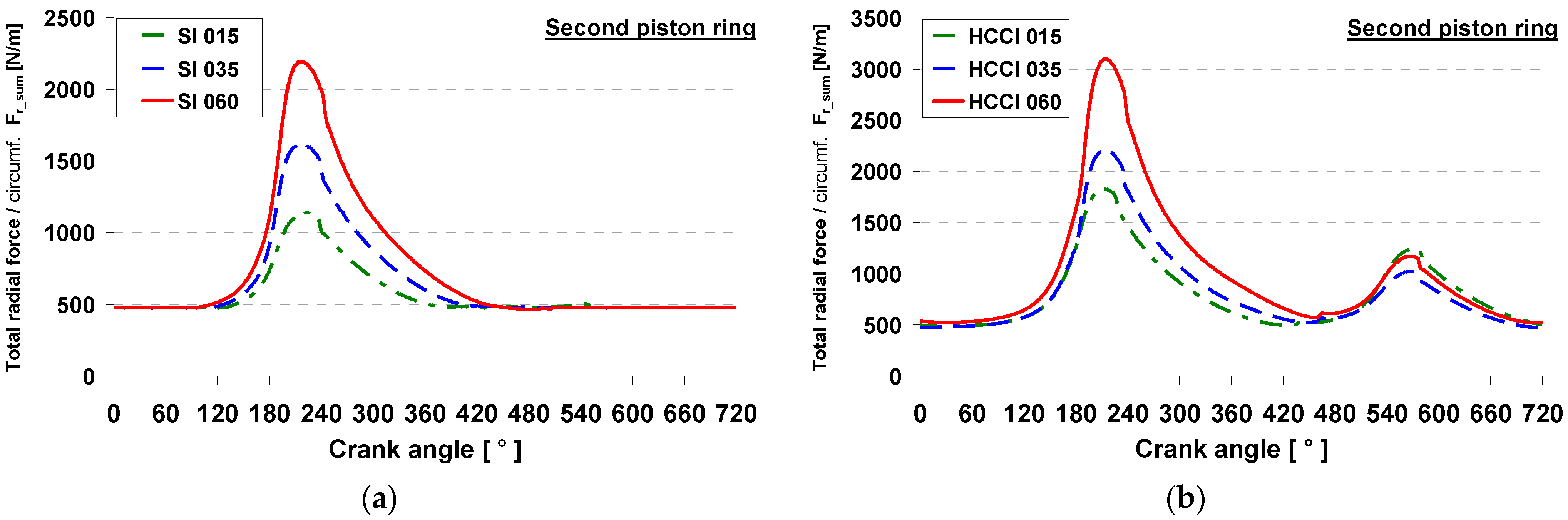
Figure 10.
Contact friction unit force of the second ring versus crank angle for (a) SI mode and (b) HCCI mode.
Figure 10.
Contact friction unit force of the second ring versus crank angle for (a) SI mode and (b) HCCI mode.
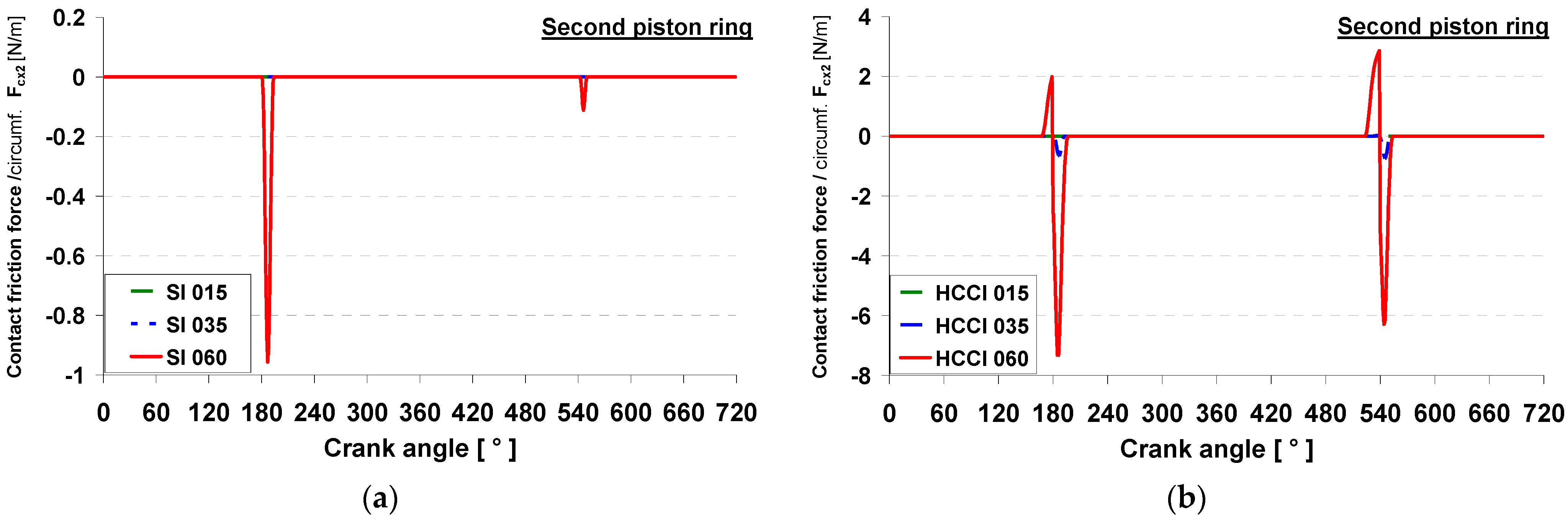
Figure 11.
Total friction unit force of the second ring versus crank angle for (a) SI mode and (b) HCCI mode.
Figure 11.
Total friction unit force of the second ring versus crank angle for (a) SI mode and (b) HCCI mode.

Figure 12.
Minimum oil film thickness of the second ring versus crank angle for (a) SI mode and (b) HCCI mode.
Figure 12.
Minimum oil film thickness of the second ring versus crank angle for (a) SI mode and (b) HCCI mode.
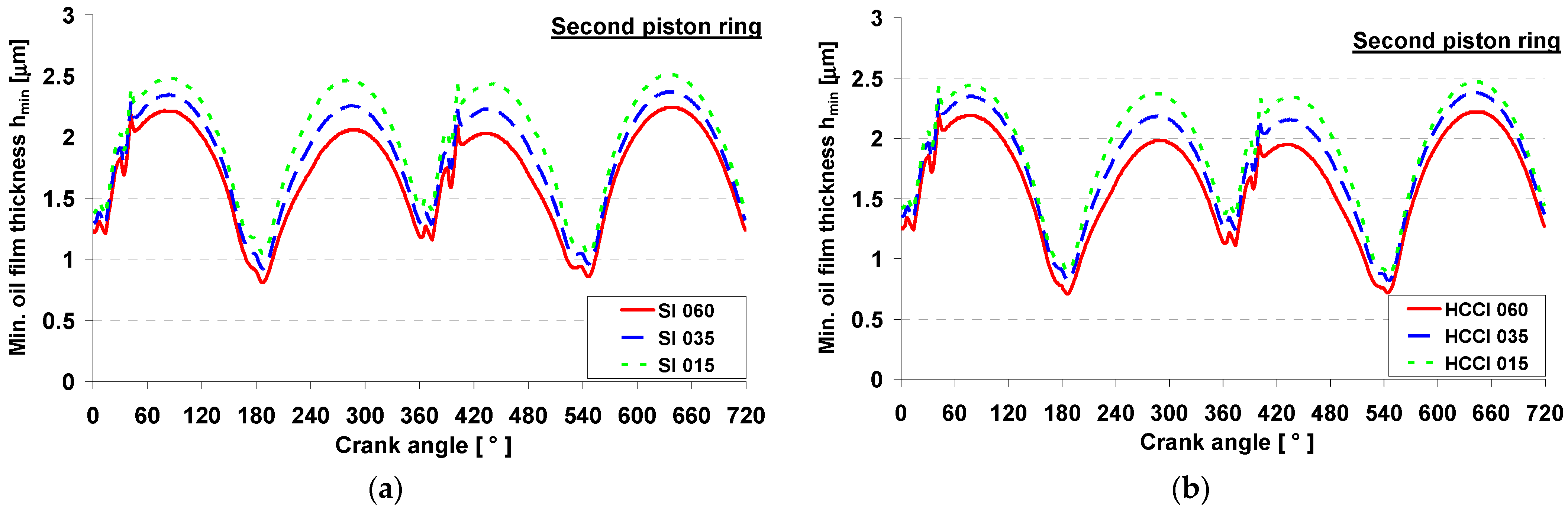
Figure 13.
Hydrodynamic friction (a) and contact friction unit force (b) versus crank angle of the oil ring for SI mode.
Figure 13.
Hydrodynamic friction (a) and contact friction unit force (b) versus crank angle of the oil ring for SI mode.
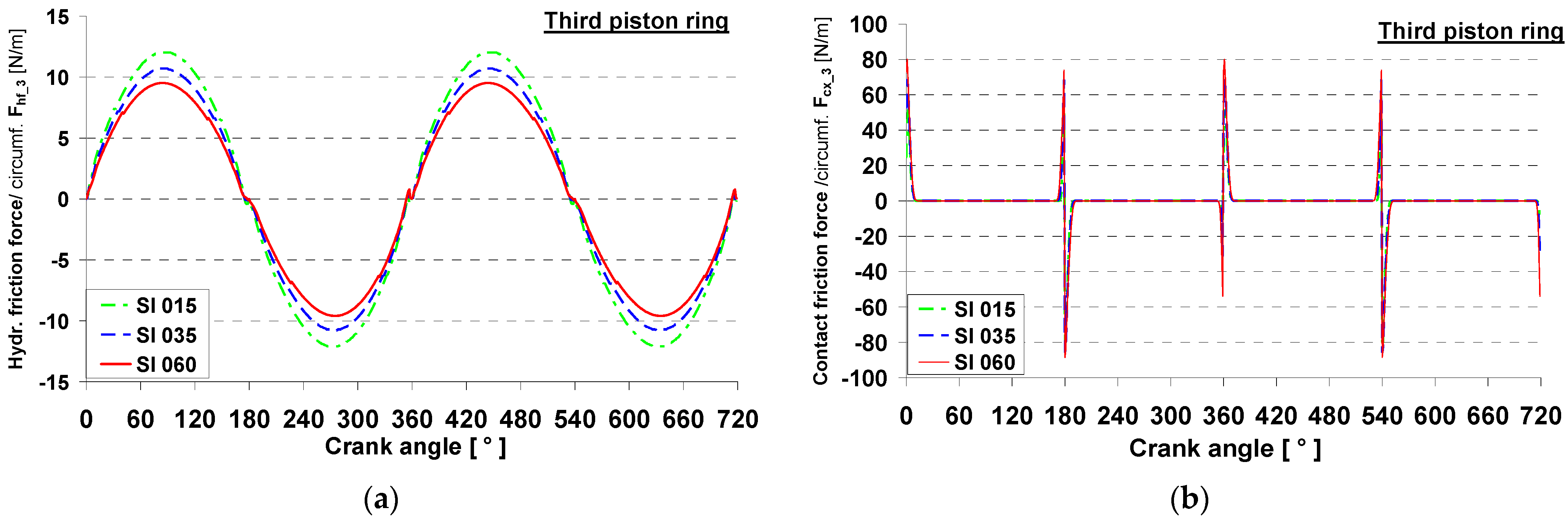
Figure 14.
Total friction unit force (a) and minimum oil film thickness (b) of the oil ring versus crank angle for SI mode at low, medium and high loads.
Figure 14.
Total friction unit force (a) and minimum oil film thickness (b) of the oil ring versus crank angle for SI mode at low, medium and high loads.
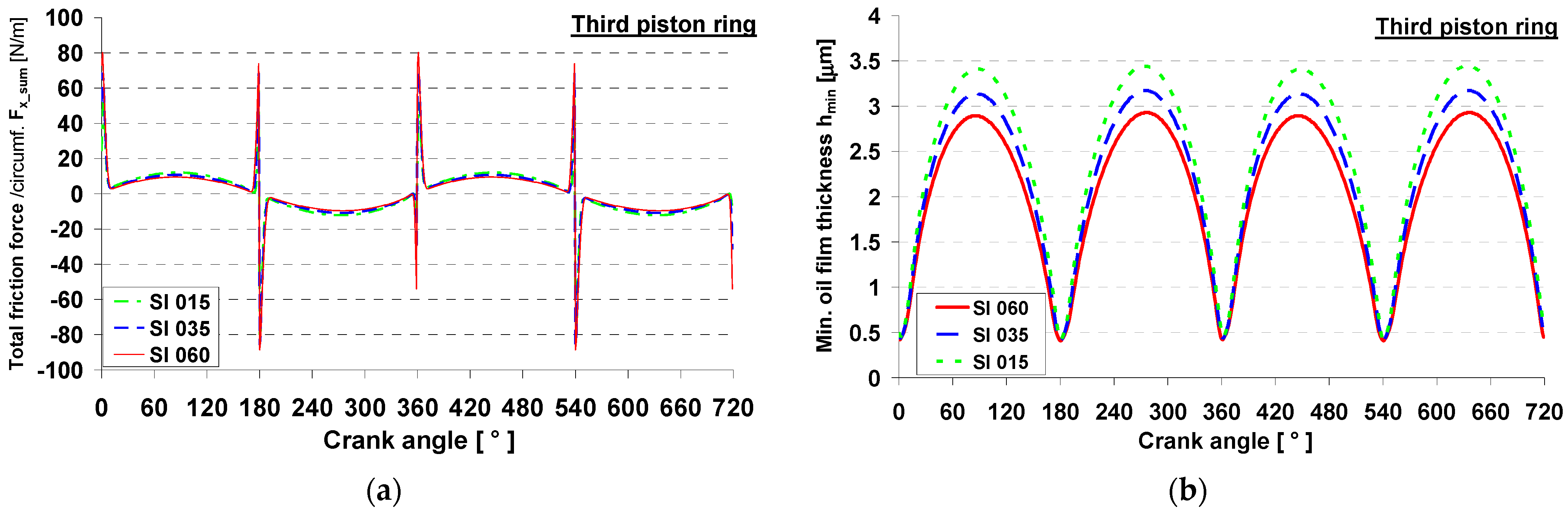
Figure 15.
Hydrodynamic and asperity contact power losses for particular rings, operation modes and engine loads.
Figure 15.
Hydrodynamic and asperity contact power losses for particular rings, operation modes and engine loads.

Table 1.
Engine specification.
| Parameter | Value |
|---|---|
| Displacement, cm3 | 498.5 |
| Nominal diameter of bore, mm | 84 |
| Stroke, mm | 90 |
| Connecting rod length, mm | 215 |
| Compression ratio | 11.7:1 |
| No. of valves | 2 |
| Fuel injector | electromagnetic, single-stream, swirl-type |
Table 2.
Main dimensions of the piston rings.
| Parameter | Top Ring | Second Ring | Oil Ring |
|---|---|---|---|
| Total axial height, mm | 1.5 | 2.0 | 4.0 |
| Upper land axial height, mm | – | – | 1.0 |
| Lower land axial height, mm | – | – | 1.0 |
| Radial width, mm | 3.7 | 3.7 | 4.15 |
| Nominal ring end gap, mm | 0.5 | 0.45 | 0.4 |
| Radius of parabolic sliding surface, mm | 180 | 180 | 244 |
| Offset of parabolic sliding surface, mm | 0.75 | 1.5 | 2.0 |
| Elastic tension force Per unit of circumference, N/m | 476 | 526 | 1190 |
| Mass, g | 11.1 | 14.8 | 24.7 |
Table 3.
Conditions of engine operation.
| Mode | IMEP [MPa] | IVO [deg] * | IVC [deg] * | EVO [deg] * | EVC [deg] * | IV Lift [mm] | EV Lift [mm] | MAP [kPa] | Excess Air Ratio [–] |
|---|---|---|---|---|---|---|---|---|---|
| SI | 0.167 | 540 | 40 | 321 | 540 | 9 | 9 | 32 | 1 |
| SI | 0.357 | 540 | 40 | 321 | 540 | 9 | 9 | 44 | 1 |
| SI | 0.595 | 540 | 40 | 321 | 540 | 9 | 9 | 55 | 1 |
| HCCI | 0.515 | 629 | 39 | 328 | 447 | 3.6 | 2.9 | 97 | 1.2 |
| HCCI | 0.342 | 625 | 35 | 341 | 460 | 3.6 | 2.9 | 95 | 1 |
| HCCI | 0.603 | 622 | 32 | 341 | 460 | 3.6 | 2.9 | 135 | 1 |
* degrees as in Figure 4.
Table 4.
Roughness parameters of surfaces.
| Parameter | Cylinder Liner | Piston Rings |
|---|---|---|
| RMS roughness, µm | 0.22 | 0.044 |
| Elastic modulus, GPa | 113 | 150 |
| Poisson’s ratio | 0.26 | 0.25 |
| Combined Parameters | Cylinder Liner and Piston Rings | |
| Asperity density, m−2 | 1.1145 × 10¹² | |
| Asperity radius, µm | 0.2 | |
Disclaimer/Publisher’s Note: The statements, opinions and data contained in all publications are solely those of the individual author(s) and contributor(s) and not of MDPI and/or the editor(s). MDPI and/or the editor(s) disclaim responsibility for any injury to people or property resulting from any ideas, methods, instructions or products referred to in the content. |
© 2023 by the authors. Licensee MDPI, Basel, Switzerland. This article is an open access article distributed under the terms and conditions of the Creative Commons Attribution (CC BY) license (https://creativecommons.org/licenses/by/4.0/).
Share and Cite
MDPI and ACS Style
Koszalka, G.; Wolff, A. Frictional Losses of Ring Pack in SI and HCCI Engine. Energies 2023, 16, 8096. https://doi.org/10.3390/en16248096
AMA Style
Koszalka G, Wolff A. Frictional Losses of Ring Pack in SI and HCCI Engine. Energies. 2023; 16(24):8096. https://doi.org/10.3390/en16248096
Chicago/Turabian StyleKoszalka, Grzegorz, and Andrzej Wolff. 2023. "Frictional Losses of Ring Pack in SI and HCCI Engine" Energies 16, no. 24: 8096. https://doi.org/10.3390/en16248096
Note that from the first issue of 2016, this journal uses article numbers instead of page numbers. See further details here.