Article

Study on the Rotation Effect on the Modal Performance of Wind Turbine Blades

1
Institute of Engineering Thermophysics, Chinese Academy of Sciences, Beijing 100190, China
2
The Key Laboratory of Wind Energy Utilization of CAS, Beijing 100190, China
3
University of Chinese Academy of Sciences, Beijing 100049, China
4
GuangDong HaiZhuang Offshore WindPower Research Center Co., Ltd., Zhanjiang 524100, China
5
Southern Marine Science and Engineering Guangdong Laboratory (Zhanjiang), Zhanjiang 524013, China
*
Authors to whom correspondence should be addressed.
Energies 2023, 16(3), 1036; https://doi.org/10.3390/en16031036
Submission received: 14 November 2022 / Revised: 1 January 2023 / Accepted: 14 January 2023 / Published: 17 January 2023

Abstract

:
With the large-scale development of wind turbines, large flexible blades bear heavier loads. In the actual rotating work of blades, the coupling of structural deformation and motion produces a dynamic stiffening effect and spin softening effect, which affects the dynamic characteristics of blades. In this study, the finite element method is used to model the NREL 5MW blade, and the dynamic stiffening and spin softening effects are investigated using the modal analysis. The influence of rotating effects on the blade’s natural frequency is revealed. It is concluded that the effect of dynamic stiffening is more significant than that of spin softening, and the comprehensive result of the two effects is not simply the superposition of them but presents obvious nonlinearity.

1. Introduction

Energy shortage is a serious problem facing the world. In the process of transforming the world’s energy structure into a renewable, sustainable development system, wind energy, as a widely distributed renewable energy, has been developed and utilized on a large scale [1], playing an important role in solving the energy crisis and environmental protection problems.
With the development of large-scale wind turbines, the blade loads increase due to the increase in length. In the field of wind power research, much research focuses on blade design [2,3], among which the dynamic characteristics analysis of wind turbine blades is increasingly concerned [4,5]. Wind turbine blades directly bear random and alternating wind loads, and the blades have relatively complex rigid, flexible coupling structures, which makes the blades more prone to vibration, thus affecting the service life of the blades [6].
Through modal analysis, the frequency and mode shape of the structure can be obtained, and the actual vibration response of the structure under the external excitation of a certain frequency can be approximately obtained [7,8,9,10]. The results of the modal analysis can make the structure avoid structural damage caused by resonance as much as possible. Therefore, modal analysis is of great significance in structural dynamic design and optimization.
When wind turbine blades rotate at a certain angular speed in practical work, the coupling of the deformation and motion of slender flexible elastomer structures leads to dynamic stiffening and spin softening effects, which further affect the dynamic characteristics of the blades. After considering the two effects, the dynamic characteristics of the actual working state of the blade are more accurately analyzed [11,12]. It is of great significance to calculate the blade vibration mode and analyze the coupling effect between the rotation of the blade and its elastic deformation for improving the performance of the wind turbine and the safe operation of the wind turbine.
In recent years, a tremendous amount of work has been conducted on the vibration of wind turbine blades. Due to the complex aerodynamic profile of the blade, the finite element method is mainly used for simulation analysis [13]. The finite element method is practical and reliable. According to different theories and models, blade finite element research can be divided into the beam element model and the shell element model. The beam model is of great significance in the development of rotating blade analysis [14,15,16,17,18]. Kane [19] established the dynamic equation through the tensile deformation along the neutral axis and proposed a modeling method for a beam with a large range of motion. Bakr et al. [20] proposed a dynamic analysis method for geometrically nonlinear flexible systems. Baumgart et al. [21] analyzed the dynamic characteristics of blades with complex aerodynamic profiles by combining the actual working characteristics of blades with the finite element method, but the analysis process is relatively complex. Naguleswaran et al. [22] analyzed the blade by equating it to a cantilever beam and applied it in many fields. All the above work shows that the dynamic stiffening effect or spin softening effect directly affects the dynamic characteristics of blades.
Compared with the beam element model, the shell model can achieve higher calculation accuracy. On the one hand, the shell is usually more representative of the outer rigid layered structure of the blade [23]. On the other hand, the shell can correctly represent the deformation of the cross section [24]. In the blade modal analysis, the first two-order calculation results of the beam model can achieve a similar accuracy to that of the shell model [25,26], but the error of the last several-order calculation results cannot be ignored. In addition, the existing commercial software beam element model cannot simulate two effects at the same time, and the analysis results of the modal characteristics of the rotating blade beam model using the software are inaccurate, so the shell element model must be used for analysis [27,28,29]. Wallrapp et al. [30] proposed an initial stress method that can improve the universality of a flexible system in simulation. Yoo et al. [31] improved the aforementioned method and successfully applied it to modal analysis in consideration of obtaining more accurate stiffening effects. Jian et al. [32] established the general finite element dynamic equation of the rotating beam based on Kane’s formula, derived the explicit three-dimensional beam element matrix of the rotating beam by using the beam section parameters, and finally calculated the natural frequency of the rotating beam and compared it with the conventional calculation. Yao et al. [33] analyzed the modal characteristics of the flexible beam under the rotating softening state.
In this paper, the finite element modeling of an SNL61d5m blade is carried out, and the influence of the dynamic stiffening and spin softening on the blade modal characteristics is comprehensively analyzed. The results are verified by comparing the results of a single-rotor wind turbine to Sandia National Laboratories’ results of the same turbine model. It is concluded that the effect of dynamic stiffening is more significant than that of spin softening, and the comprehensive result of the two effects is not simply the superposition of them but presents obvious nonlinearity.
The results are helpful in improving blade stability. By determining the optimal operating environment and imposing necessary constraints, the occurrence of blade vibration can be effectively suppressed, and the blade can meet the required performance requirements, which is helpful in studying the fatigue life and structural strength of blade segments and effectively avoiding the potential safety hazards caused by blade vibration.

2. Rotational Effect

For blade modal analysis, the blade coordinate system is established, as shown in Figure 1.

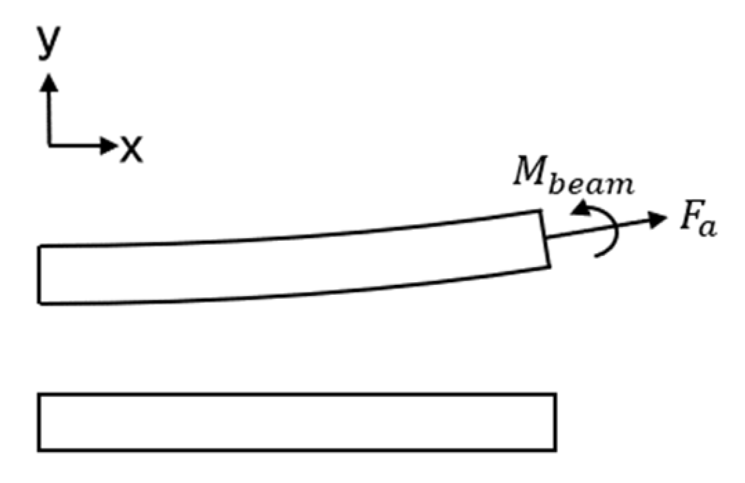
2.1. Dynamic Stiffening Effect

Kane [15] first proposed the concept of dynamic stiffening in 1987. The essence of the dynamic stiffness effect is the phenomenon that the coupling between the spatial rotation and deformation of the structure increases the stiffness [35]. Its generation can be illustrated by the beam model in Figure 2 [36].
If the small deformation hypothesis theory is adopted, the coupling of system motion and deformation can be ignored, and hence the bending moment is not affected by the axial force. However, in reality, the coupling of motion and deformation cannot be ignored, which leads to the additional bending moment generated by the axial force. The additional bending moment increases with the increase in the axial force. In the rotating system, as the axial force, the centrifugal force increases with the rotational speed, so the additional bending moment and the additional stiffness also increase [37]. The additional bending moment can be expressed as
M b e a m = F a y x d x ,
where F a is the axial force.
In case of ignoring the damping effect, the vibration equation of the three-dimensional modal system considering dynamic stiffening is [38]:
M u ¨ + K + S u = f t ,
where [M] is the mass matrix of the blade system, [K] is the stiffness matrix of the whole blade system, {f(t)} is the external excitation load vector and [S] is the system stress stiffness matrix. In the nonlinear finite element analysis, the solid element can be discretized.

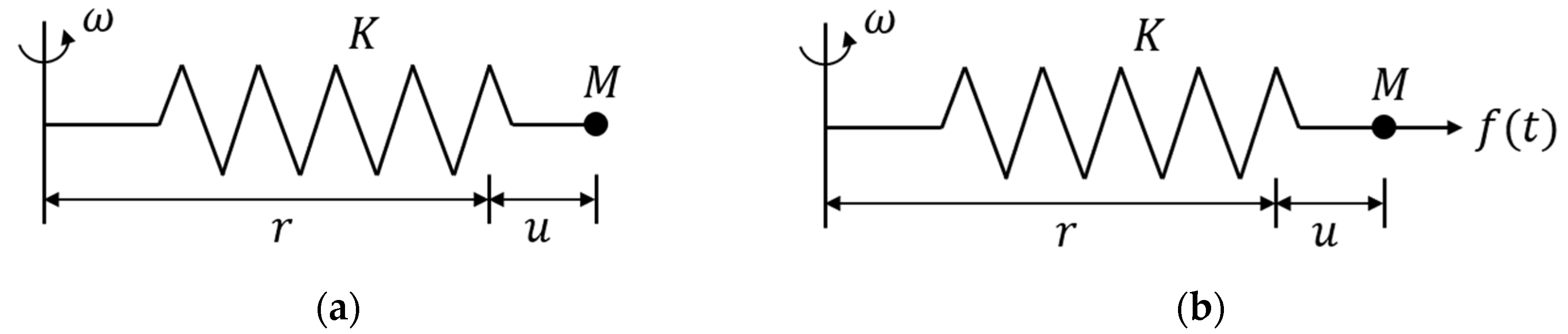
2.2. Spin Softening Effect

With the flexible wind turbine blades rotating in a large range, the stiffness of the blades decreases because of the influence of geometric nonlinearity. This phenomenon is called the spin-softening effect. The generation of that can be illustrated by a simple rotary spring model in Figure 3 [39].
With the small deformation hypothesis theory being adopted and the deformation being considered negligible, the system equilibrium equation for the model shown in Figure 3a is:
K u = M ω 2 r ,
where K is the spring stiffness, u is the displacement of the particle relative to its free position, M is the mass of the particle, ω is the angular velocity of system rotation and r is the vertical distance from the free position of the particle to the rotation axis.
By adding an exciting force on the mass point outward along the spring axis in Figure 3b, the system equilibrium equation becomes
M u ¨ + K u = f t ,
Considering the influence of deformation, Equation (3) becomes:
K u = M ω 2 r + u .
The equivalent stiffness of the vibration system K ¯ is defined as:
K ¯ = K ω 2 M ,
Correspondingly, Equation (4) becomes:
M u ¨ + K ¯ u = f t ,
In the finite element analysis, the above particle is regarded as a node in the three-dimensional finite element model. By considering the spin softening effect, Equation (6) can be directly extended to a three-dimensional format to obtain the stiffness of a node of the three-dimensional finite element model, which is given as
K ¯ = K Ω 2 M ,
Ω 2 = ω y 2 + ω z 2 ω x ω y ω x ω z ω x ω y ω x 2 + ω z 2 ω y ω z ω x ω z ω y ω z ω x 2 + ω y 2 .
Here, ωx, ωy and ωz are the components of angular velocity in x, y and z directions, respectively. In practical analysis, a certain coordinate axis is usually taken as the rotation axis, and the angular velocity components in the other two directions are zero. Hence the calculation is simplified. In Equation (9), the non-diagonal quantities of the matrix are all zero, and a symmetric matrix is obtained. The mass matrix [M] can be expressed as follows:
M = M x x M y y M z z .
Equation (8) can be expanded as follows:
K ¯ x x = K x x M x x ω y 2 + ω z 2 ,
K ¯ y y = K y y M y y ω x 2 + ω z 2 ,
K ¯ z z = K z z M z z ω x 2 + ω y 2 ,
where, K x x ,   K y y and K z z are the stiffness coefficient of the node along the x, y and z directions calculated, respectively. K ¯ x x , K ¯ y y and K ¯ z z are the modified stiffness coefficient of the node in the x, y and z directions, respectively, after considering the spin-softening effect.
Considering the spin softening, the vibration equation of the three-dimensional finite element model of the whole system can be expressed as:
M u ¨ + C u ˙ + K ¯ u = f t .
When both dynamic stiffening and spin softening are considered, the modal analysis can be reduced to the generalized eigenvalue problem of the following equation.
K + S Ω 2 M ω g r 2 M ϕ = 0 ,
where [S] is the stress stiffness matrix caused by dynamic stiffness, ωgr is the natural frequency of the system considering dynamic stiffening and rotational softening effects and ϕ is the characteristic vector of the model.

3. Modal Analysis of Blades
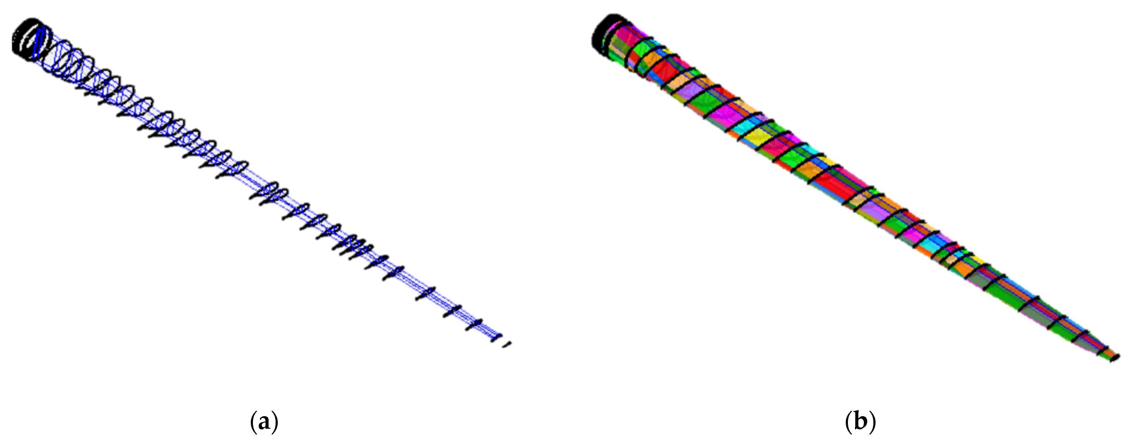
3.1. Blade Model

The three-dimension modeling software NuMAD (numerical manufacturing and design tool) developed by Sandia National Laboratories is used to establish the geometric model. The model used in the analysis is SNL61d5m [40], which is designed by Sandia Laboratory with reference to the NREL 5MW model. According to the design report [40], the geometric parameters of the blade and the parameters related to blade layering are set. The sections of the blade are divided by materials, and the three-dimensional geometric model of the blade is obtained, as shown in Figure 4.
The geometric model was imported into ANSYS software for grid generation. The element type of blade was the 8-node 3D shell element SHELL281, which divided the blade into 103,542 nodes and 104,987 elements. The connection between the blade root and the hub is regarded as a rigid connection, the blade is simplified as a cantilever beam structure, and full constraints are imposed at the blade root. Finally, the finite element model of the blade is established, as shown in Figure 5.

3.2. Modal Analysis

According to the vibration theory, the vibration energy is concentrated in the low-order frequency vibration, which makes the low-order vibration more dangerous than the high-order vibration. Therefore, the first six-order modal shapes and natural frequencies are selected for research. Natural frequencies and mode shape comparisons are shown in Table 1. In the present analysis, it is assumed that the blade rotation angular speed is the rated value of 12.1 r/min, and the effects of the dynamic stiffening and spin softening are considered. The root fixed constraint is applied to the model. However, in the actual working condition, the connection between the blade and hub is performed by bolting, which is not completely rigid. Therefore, the calculated natural frequencies are slightly higher than that of the actual value.
According to Table 1, The results are verified by comparing the results of a single-rotor wind turbine to Sandia National Laboratories’ results of the same turbine model. At the rated speed, the first natural frequency of the blade is 0.87 Hz, which is far greater than the blade rotation frequency and 4.32 times the blade rotation frequency. It does not coincide with the integral times of the blade rotation frequency. The coupling resonance phenomenon of blade vibration and rotation does not occur at the rated speed. Therefore, the natural frequency of the wind turbine blade meets the design requirements. In addition, the first six modal shapes after modal expansion are shown in Figure 6.
The following conclusions can be drawn from the above figure:
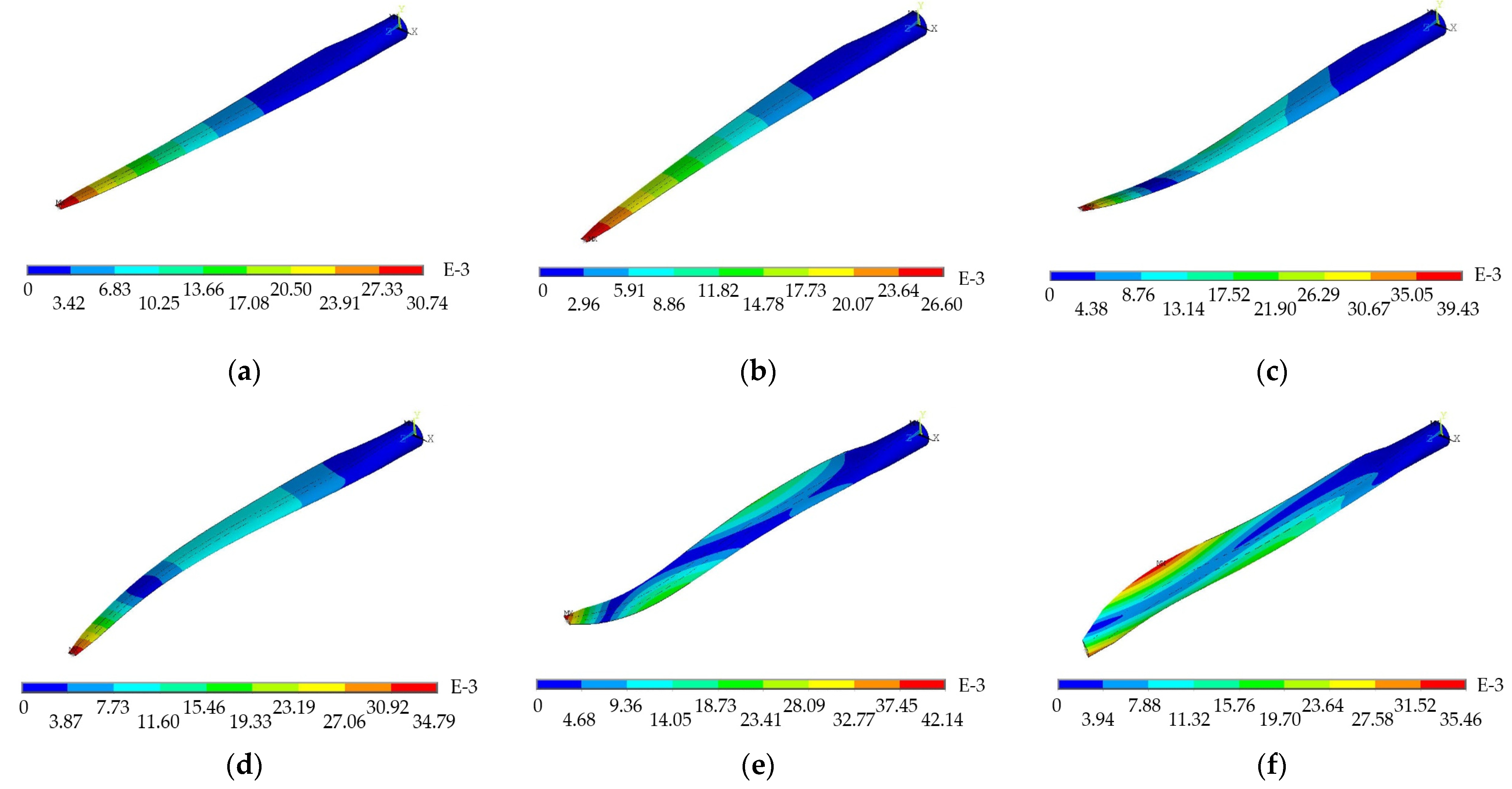
  • The first mode profile is flapwise; the second mode shape is edgewise; the third mode shape is flapwise; the fourth mode shape is a combination of edgewise and flapwise; and the fifth and sixth mode shapes are a combination of flapwise, edgewise and torsion.
  • The torsional phenomena of blades only occur at high order, indicating that the torsional vibration frequency is higher than the vibration frequency of flapwise and edgewise bending. Since the vibration energy of the blade is concentrated in the first two orders, the bending vibration in the flapwise and the edgewise is the main vibration of the blade during the blade vibration process. Compared with the bending vibration, the contribution of the torsional vibration can be neglected.
  • According to the structural mechanics and elasticity, there are fixed points, which are called vibration nodes, while blades rotate. When the frequency of the external force is close to the natural frequency of the blade, blade resonance is induced, causing severer structure vibration and finally breaking the blade at the vibration nodes. Most of the vibration nodes in the figure appear at the blade root and one-third of the distance from the blade tip, which is similar to the fatigue fracture point of most blades (blade root, blade tip and one-third of the distance from the blade tip). It is verified that the blade root and one-third of the distance from the blade tip are dangerous sections that are prone to fatigue damage.

4. Rotation Effect on Mode

Effects of dynamic stiffening and spin softening on natural frequencies of blades are numerically analyzed. In the analysis, the blade rotating angular velocity increases from 0 r/min to 12.1 r/min. The following four different situations are considered: Test 1—dynamic stiffening and spin softening effects are not considered, and thus the angular velocity is zero; Test 2—only the dynamic stiffening effect is considered; Test 3—only the rotating softening effect is considered; Test 4—both two effects are considered. The results are shown in Figure 7.
The following conclusions can be drawn from the above figure:
4.
The dynamic stiffening effect increases the natural frequency of the blade, which is more obvious in the low-order modal analysis. The rotating softening effect reduces the natural frequency of the blade, which is also more significant at low order.
5.
The degree of frequency increase due to dynamic stiffening is related to the blade vibration mode, and its influence on the flapwise vibration is greater than its influence on the edgewise vibration. The degree of frequency reduction caused by spin softening is also related to the blade vibration mode, and its influence on the edgewise vibration is greater than that on the flapwise vibration.
6.
Effects of dynamic stiffening and spin softening increase with the increase in angular velocity. As the angular velocity increases, the coupling effect of blade deformation and blade rotation becomes more obvious, and the centrifugal force has a greater impact on the blade deformation. Therefore, there is a positive correlation between the impact of the two effects on the natural frequency and the angular velocity.
7.
The effect of dynamic stiffening is more significant than that of spin softening, and the results obtained by considering both effects are not only the superposition of considering any one of the effects.

5. Conclusions

In this paper, the modal analysis was conducted on an SNL61d5m blade to obtain the first six natural frequencies and modal shapes of the blade at the rated speed. The results were verified by comparing the results of a single-rotor wind turbine to Sandia National Laboratories’ results of the same turbine model. The vibration direction of each order of the blade was revealed. In addition, the dangerous section where the vibration node of the blade is located is also found to be at the root of the blade and one-third of the distance from the tip of the blade, which requires special attention in design.
By comparing and analyzing the influence of the dynamic stiffening effect and spin softening effect on blade frequency, the following conclusions are achieved: The dynamic stiffening effect increases the natural frequency of the blade, which is more obvious in the lower order. In addition, the influence of the dynamic stiffening effect is greater in the flapwise than that in the edgewise; the spin softening effect reduces the natural frequency of the blade, which is also obvious in the lower order. In addition, the influence of the spin-softening effect is greater in the edgewise than that in the flapwise. The effects of these two effects are positively correlated with the rotating angular velocity of the blade, the effect of dynamic stiffening is more significant than that of spin softening, and the results obtained by considering both effects are not only the superposition of considering any one of the effects.
The results are helpful in improving blade stability. By determining the optimal operating environment and imposing necessary constraints, the occurrence of blade vibration can be effectively suppressed, and the blade can meet the required performance requirements, which is helpful in studying the fatigue life and structural strength of blade segments in the future.

Author Contributions

Formal analysis, S.Z. and X.W.; resources, W.W. and Y.H.; writing—original draft preparation, Y.C.; writing—review and editing, C.C. and T.Z.; supervision, Q.L.; funding acquisition, Y.H. All authors have read and agreed to the published version of the manuscript.

Funding

This research was funded by National Natural Science Foundation China (Nos. 52176212 and 52206283), National Engineering Research Center for Offshore Windpower (No. HSFD22001), Southern Marine Science and Engineering Guangdong Laboratory (Zhanjiang) (ZJW-2019-02) and Guangdong Branch of National Engineering Research Center for Offshore Windpower (No. 2019B090904005).

Data Availability Statement

Not applicable.

Conflicts of Interest

The authors declare no conflict of interest.

References

  1. Boudounit, H.; Tarfaoui, M.; Saifaoui, D.; Nachtane, M. Structural analysis of offshore wind turbine blades using finite element method. Wind Eng. 2020, 44, 168–180. [Google Scholar] [CrossRef]
  2. Pellegrino, A.; Meskell, C. Vortex shedding from a wind turbine blade section at high angles of attack. J. Wind Eng. Ind. Aerodyn. 2013, 121, 131–137. [Google Scholar] [CrossRef] [Green Version]
  3. Pourazarm, P.; Caracoglia, L.; Lackner, M.; Modarres-Sadeghi, Y. Stochastic analysis of flow-induced dynamic instabilities of wind turbine blades. J. Wind Eng. Ind. Aerodyn. 2015, 137, 37–45. [Google Scholar] [CrossRef]
  4. Khan, M.; Iqbal, M. Dynamic modeling and simulation of a small wind–fuel cell hybrid energy system. Renew. Energy 2005, 30, 421–439. [Google Scholar] [CrossRef]
  5. Tapia, A.; Tapia, G.; Ostolaza, J.; Saenz, J. Modeling and control of a wind turbine driven doubly fed induction generator. IEEE Trans. Energy Convers. 2003, 18, 194–204. [Google Scholar] [CrossRef] [Green Version]
  6. Zheng, Y.; Cao, Y.; Zhang, C.; He, Z. Structural Optimization Design of Large Wind Turbine Blade considering Aeroelastic Effect. Math. Probl. Eng. 2017, 2017, 1–7. [Google Scholar] [CrossRef] [Green Version]
  7. Lee, J.-W.; Lee, J.-S.; Han, J.-H.; Shin, H.-K. Aeroelastic analysis of wind turbine blades based on modified strip theory. J. Wind Eng. Ind. Aerodyn. 2012, 110, 62–69. [Google Scholar] [CrossRef]
  8. Ismaiel, A.; Yoshida, S. Aeroelastic Analysis of a Coplanar Twin-Rotor Wind Turbine. Energies 2019, 12, 1881. [Google Scholar] [CrossRef] [Green Version]
  9. Kevin, M.; Ricardo, S.; Nickolas, V. System design of a wind turbine using a multi-level optimization approach. Renew. Energy 2012, 43, 101–110. [Google Scholar]
  10. Timmer, W.A.; Van Rooij, R.P.J.O.M. Summary of the Delft University Wind Turbine Dedicated Airfoils. J. Sol. Energy Eng. 2003, 125, 488–496. [Google Scholar] [CrossRef]
  11. Murtagh, P.; Basu, B.; Broderick, B. Along-wind response of a wind turbine tower with blade coupling subjected to rotationally sampled wind loading. Eng. Struct. 2005, 27, 1209–1219. [Google Scholar] [CrossRef]
  12. Lee, D.; Hodges, D.H.; Patil, M.J. Multi-flexible-body Dynamic Analysis of Horizontal Axis Wind Turbines. Wind Energy 2002, 5, 281–300. [Google Scholar] [CrossRef]
  13. Lesaffre, N.; Sinou, J.-J.; Thouverez, F. Stability analysis of rotating beams rubbing on an elastic circular structure. J. Sound Vib. 2007, 299, 1005–1032. [Google Scholar] [CrossRef] [Green Version]
  14. Zhu, T.-L. The vibrations of pre-twisted rotating Timoshenko beams by the Rayleigh–Ritz method. Comput. Mech. 2011, 47, 395–408. [Google Scholar] [CrossRef]
  15. Younesian, D.; Esmailzadeh, E. Non-linear vibration of variable speed rotating viscoelastic beams. Nonlinear Dyn. 2010, 60, 193–205. [Google Scholar] [CrossRef]
  16. Younesian, D.; Esmailzadeh, E. Vibration suppression of rotating beams using time-varying internal tensile force. J. Sound Vib. 2011, 330, 308–320. [Google Scholar] [CrossRef]
  17. Piovan, M.; Machado, S. Thermoelastic dynamic stability of thin-walled beams with graded material properties. Thin-Walled Struct. 2011, 49, 437–447. [Google Scholar] [CrossRef]
  18. Arvin, H.; Nejad, F.B. Non-linear modal analysis of a rotating beam. Int. J. Non-Linear Mech. 2011, 46, 877–897. [Google Scholar] [CrossRef]
  19. Kane, T.R.; Ryan, R.R.; Banerjeer, A.K.; Banerjee, A.K. Dynamics of a cantilever beam attached to a moving base. J. Guid. Control. Dyn. 1987, 10, 139–151. [Google Scholar] [CrossRef]
  20. Bakr, E.; Shabana, A. Geometrically nonlinear analysis of multibody systems. Comput. Struct. 1986, 23, 739–751. [Google Scholar] [CrossRef]
  21. Baumgart, A. A mathematical model for wind turbine blades. J. Sound Vib. 2002, 251, 1–12. [Google Scholar] [CrossRef]
  22. Naguleswaran, S. Lateral Vibration of a Centrifugally Tensioned Uniform Euler-Bernoulli Beam. J. Sound Vib. 1994, 176, 613–624. [Google Scholar] [CrossRef]
  23. Cárdenas, D.; Escárpita, A.A.; Elizalde, H.; Aguirre, J.J.; Ahuett, H.; Marzocca, P.; Probst, O. Numerical validation of a finite element thin-walled beam model of a composite wind turbine blade. Wind Energy 2011, 15, 203–223. [Google Scholar] [CrossRef]
  24. Nabi, S.M.; Ganesan, N. Comparison of beam and plate theories for free vibrations of metal matrix composite pre-twisted blades. J. Sound Vib. 1996, 189, 149–160. [Google Scholar] [CrossRef]
  25. Chen, H.; Yu, W.; Capellaro, M. A critical assessment of computer tools for calculating composite wind turbine blade properties. Wind Energy 2010, 13, 497–516. [Google Scholar] [CrossRef]
  26. Hodges, D.H.; Yu, W. A rigorous, engineer-friendly approach for modelling realistic, composite rotor blades. Wind Energy 2007, 10, 179–193. [Google Scholar] [CrossRef]
  27. Rao, J.S.; Sreenivas, R. Dynamics of a three level rotor system using solid elements. In Proceedings of the International Joint Power Generation Conference, Atlanta, GA, USA, 16–19 June 2003. [Google Scholar]
  28. Rao, J.S. Rotor dynamics of aircraft gas turbine engines. In Proceedings of the International Conference on Aerospace Science and Technology, Bangalore, India, 26–28 June 2008. [Google Scholar]
  29. Yao, X.S. Vibration Analysis of Transmission Shafts Using Solid Models. Appl. Mech. Mater. 2013, 397–400, 418–421. [Google Scholar] [CrossRef]
  30. Wallrapp, O.; Schwertassek, R. Representation of geometric stiffening in multibody system simulation. Int. J. Numer. Methods Eng. 1991, 32, 1833–1850. [Google Scholar] [CrossRef]
  31. Yoo, H.; Ryan, R.; Scott, R. Dynamics of flexible beams undergoing overall motions. J. Sound Vib. 1995, 181, 261–278. [Google Scholar] [CrossRef]
  32. Yao, X.S.; Chen, J.; Zheng, C.L. Dynamics of flexible beams based on spin softening. Chin. J. Appl. Mech. 2014, 31, 582–587. (In Chinese) [Google Scholar]
  33. Jian, K.L.; Yin, X.G. Computation of natural frequencies of a rotating beam. J. Chongqing Univ. Nat. Sci. Ed. 2001, 24, 35–39. (In Chinese) [Google Scholar]
  34. Vorpahl, F.; Popko, W. Description of the Load Cases and Output Sensors to be Simulated in the OC4 Project under IEA Wind Annex 30; Fraunhofer Institute for Wind Energy and Energy System Technology IWES: Bremerhaven, Germany, 2016. [Google Scholar]
  35. Jeha, R.; Kim, S.S.; Kim, S.S. A general approach to stress stiffening effects on flexible multibody dynamic systems. Mech. Based Des. Struct. Mach. 1994, 22, 157–180. [Google Scholar]
  36. Trindade, M.A.; Sampaio, R. Dynamics of Beams Undergoing Large Rotations Accounting for Arbitrary Axial Deformation. J. Guid. Control Dyn. 2002, 25, 634–643. [Google Scholar] [CrossRef] [Green Version]
  37. Liao, R.D.; Zuo, Z.X.; Chen, H.; Zou, W.S.; Rong, K.L. The Modal Characteristics Study of Turbine Blades with Considering the Influence of Spin Softening. Trans. CSICE (Chin. Soc. Intern. Combust. Engines) 2000, 18, 77–79. (In Chinese) [Google Scholar]
  38. Clough, R.W.; Penzien, J. Dynamics of Structures, 2nd ed.; McGraw-Hill College: New York, NY, USA, 1975; p. 105. [Google Scholar]
  39. Iwasaki, A.; Todoroki, a.; Shimamura, Y.; Kobayashi, H. Unsupervised structural damage diagnosis based on change of response surface using statistical tool-(application to damage detection of composite structure). JSME Int. J. Ser. A-Solid Mech. Mater. Eng. 2004, 47, 1–7. [Google Scholar] [CrossRef]
  40. Brian, R.R. Definition of a 5MW/61.5m Wind Turbine Blade Reference Model; Sandia National Laboratories: Albuquerque, NM, USA; Livermore, CA, USA, 2013. [Google Scholar]
Figure 1. Blade coordinate system [7,34].
Energies 16 01036 g001
Figure 2. Dynamic stiffness of a beam model.
Energies 16 01036 g002
Figure 3. Spring-mass model: (a) spring-mass rotation model; (b) spring-mass rotational vibration model.
Energies 16 01036 g003
Figure 4. Three-dimensional geometric model of SNL61d5m blade: (a) sections of blade; (b) three-dimensional geometric model of blade.
Energies 16 01036 g004
Figure 5. Finite element model of SNL61d5m blade: (a) finite element model of blade; (b) finite element model of blade interior.
Energies 16 01036 g005
Figure 6. First six mode shapes of blade: (a) first mode profile; (b) second mode profile; (c) third mode profile; (d) fourth mode profile; (e) fifth mode profile; (f) sixth mode profile. Contours are colored by vibration deformation in meter.
Energies 16 01036 g006
Figure 7. Dependence of the natural frequency on the rotational speed for the (a) first order, (b) second order, (c) third order, (d) fourth order, (e) fifth order, (f) sixth order. Comparisons of four test conditions are included in each subfigure.
Energies 16 01036 g007aEnergies 16 01036 g007b
Table 1. The first six natural frequencies of the blade. Data from [40].
ModeCalculated (Hz)Reference (Hz)Description
10.87100.8701st flapwise bending
21.05761.061st edgewise bending
32.68062.682nd flapwise bending
43.90843.912nd edgewise bending
55.57025.573rd flapwise bending
66.45016.451st torsion
Disclaimer/Publisher’s Note: The statements, opinions and data contained in all publications are solely those of the individual author(s) and contributor(s) and not of MDPI and/or the editor(s). MDPI and/or the editor(s) disclaim responsibility for any injury to people or property resulting from any ideas, methods, instructions or products referred to in the content.

