
Decoupled Speed and Flux Control of Three-Phase PMSM Based on the Proportional-Resonant Control Method


Abstract
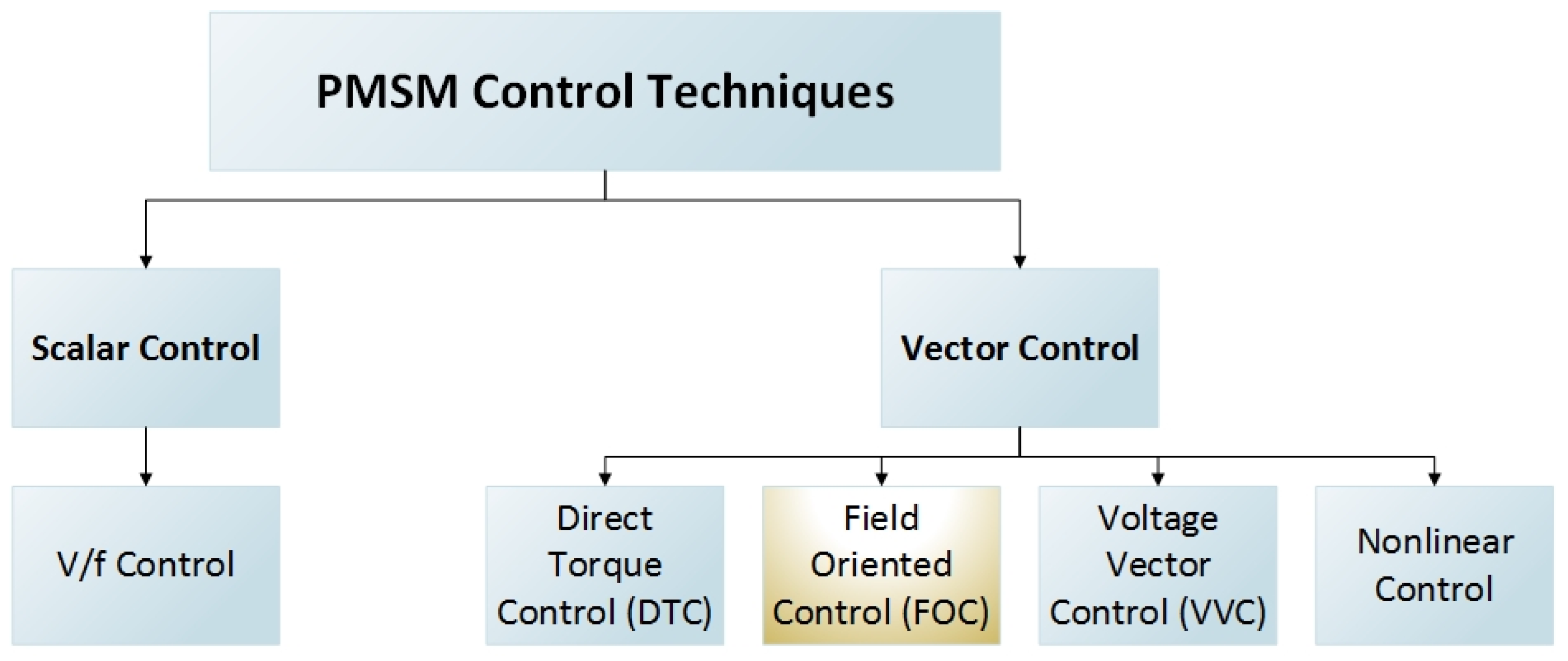
:1. Introduction
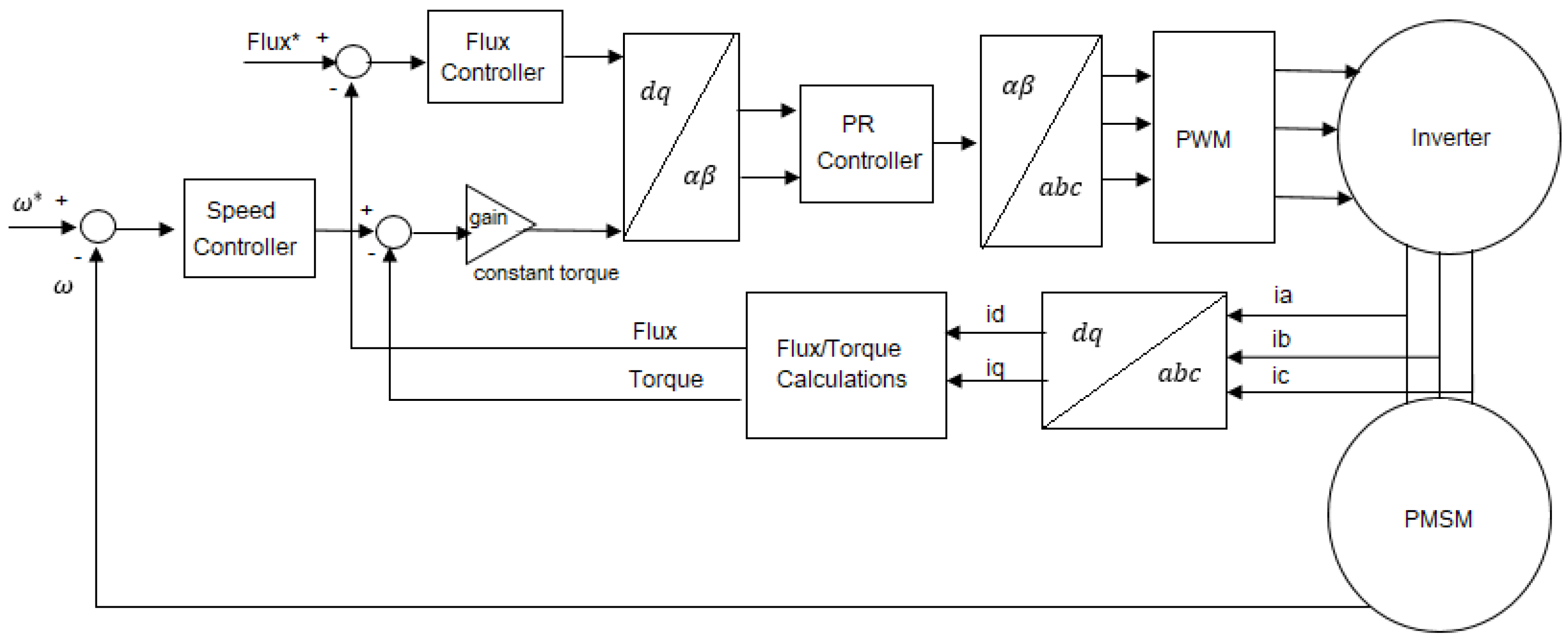
- The speed and flux decoupled controllers are proposed to control the dq-axis current through the PR controller.
- Both speed and flux control are achieved separately.
- The PR controller is proposed to control the dq-axis currents and generate the reference voltages.
- This method does not require a phase-locked loop (PLL), which makes it simpler.
- No flux or torque observer is required, which makes the overall control strategy less complex.
2. The Mathematical Model of PMSM
3. Control Algorithm Description
3.1. The Speed and Flux Controllers Design Using PI Controller
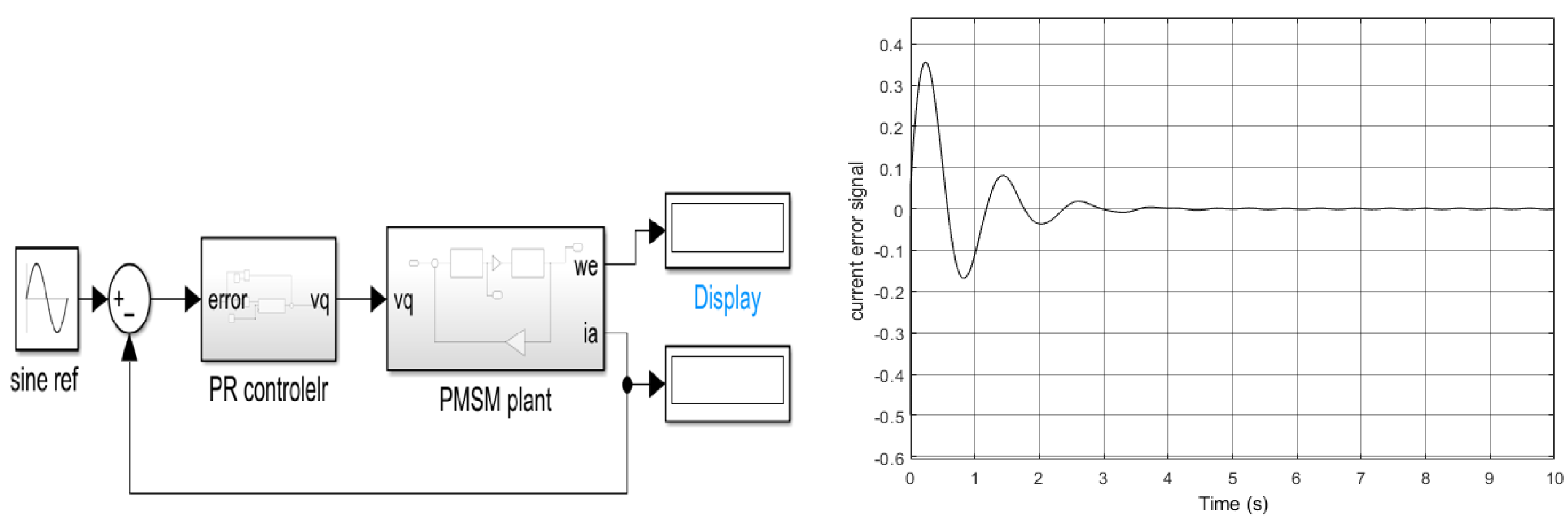
3.2. The Current Controller Design Using a PR Controller
- The main target of the PR controller is to make the measured current equal to the reference current; in other words, make the error equal to zero.
- The gain is first set to zero.
- can be increased from zero until sustained oscillations in the error waveform occur at .
- Set .
- The value of can be increased from 0 until a zero steady-state error occurred.
- Note that a larger value can help to eliminate the steady-state error and reduce the settling time, but it creates a larger overshoot. There is a trade-off between steady-state error and overshoot. Choose the suitable value of for your desired overshoot and settling time.
4. PMSM Performance Analysis and Simulation Results
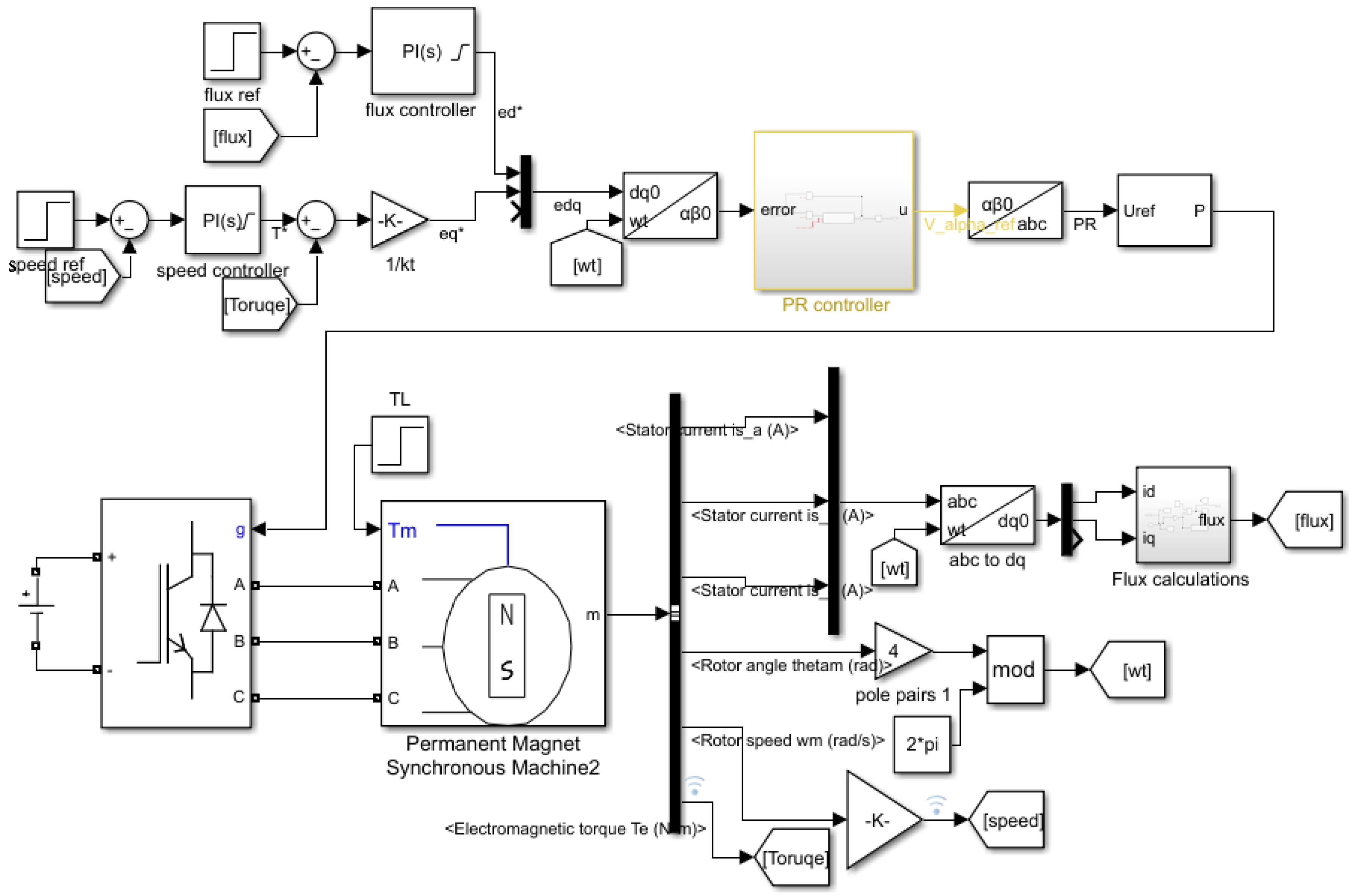
4.1. Motor Specifications, Controller Design, and Simulation Model
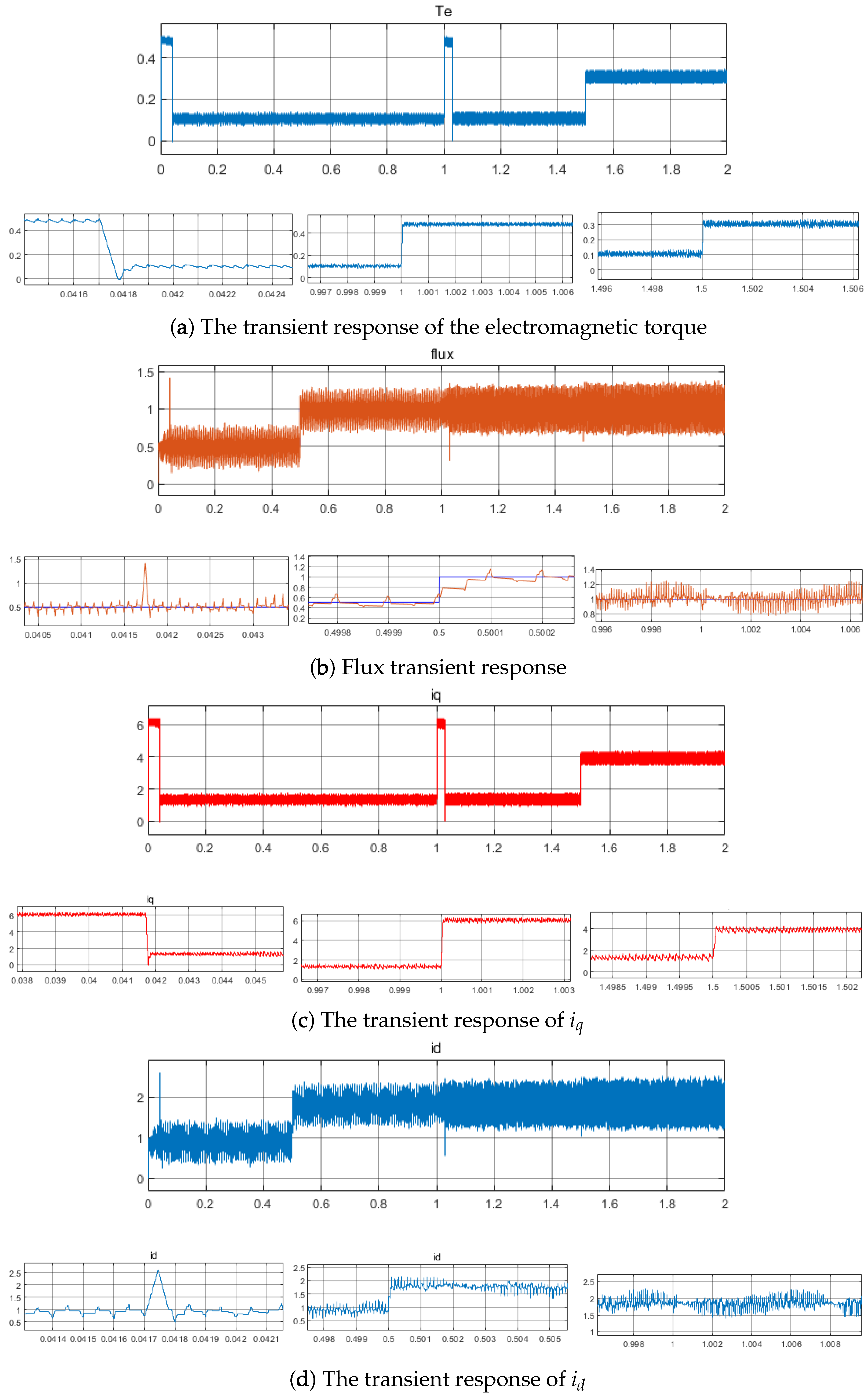
4.2. PMSM Simulation Performance
5. Experimental Analysis and Results
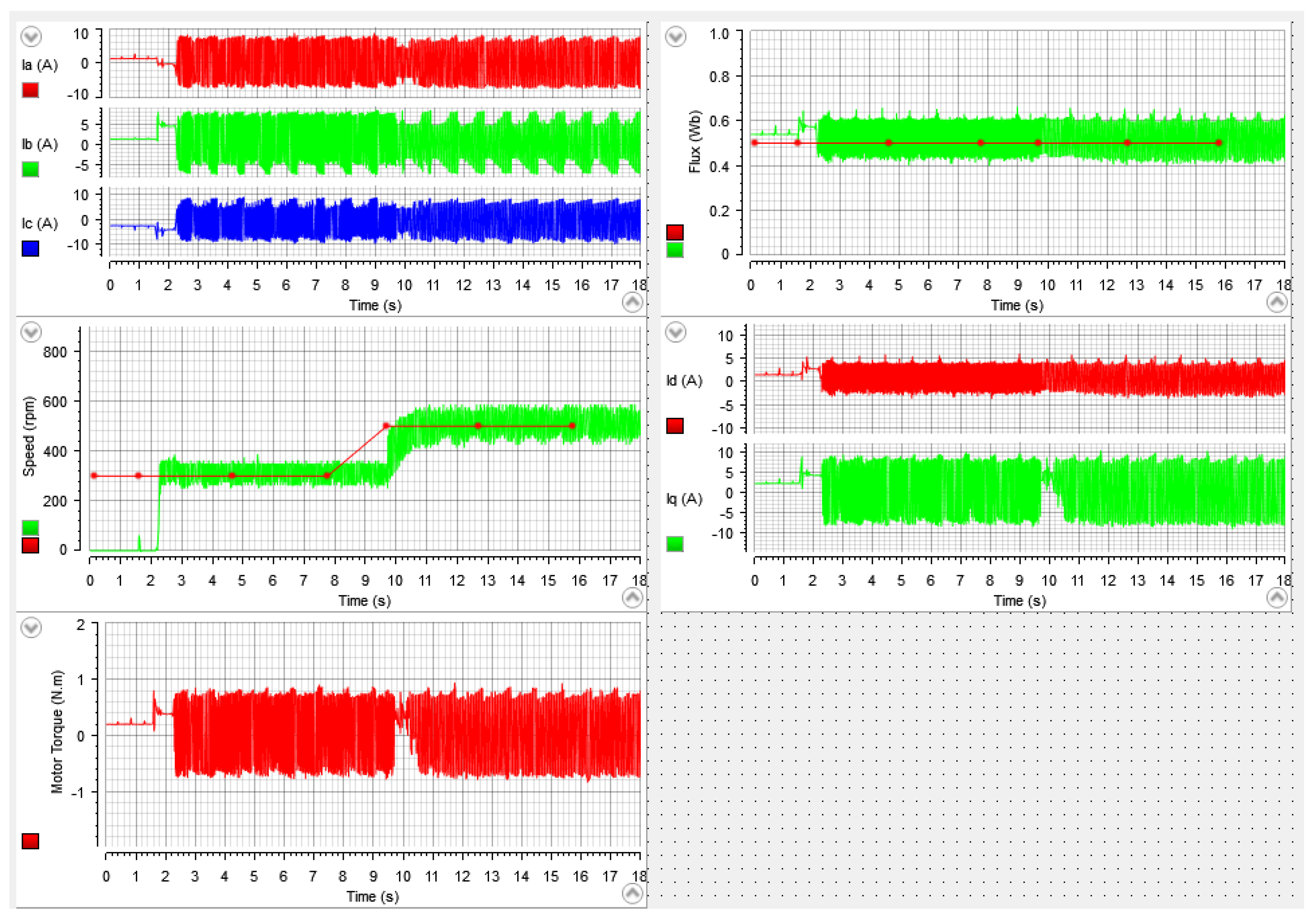
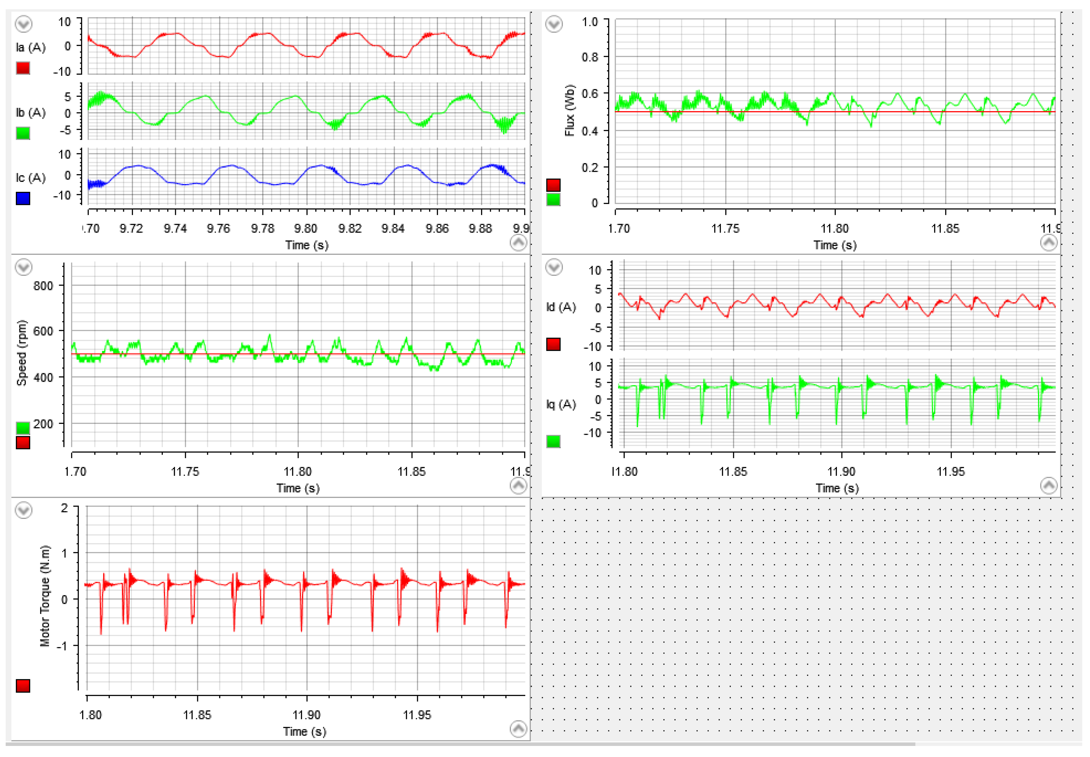
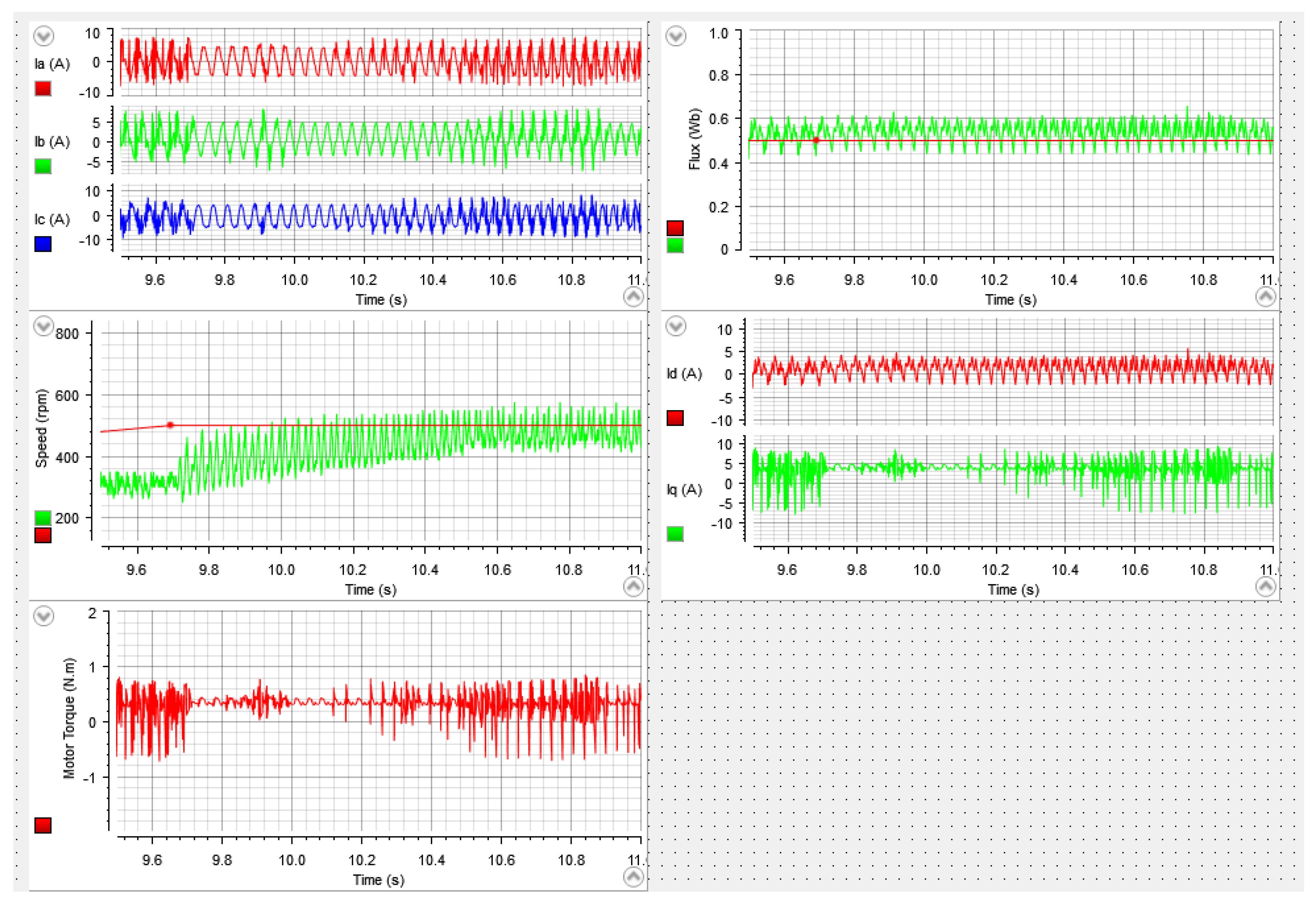
5.1. Case 1: Speed Change
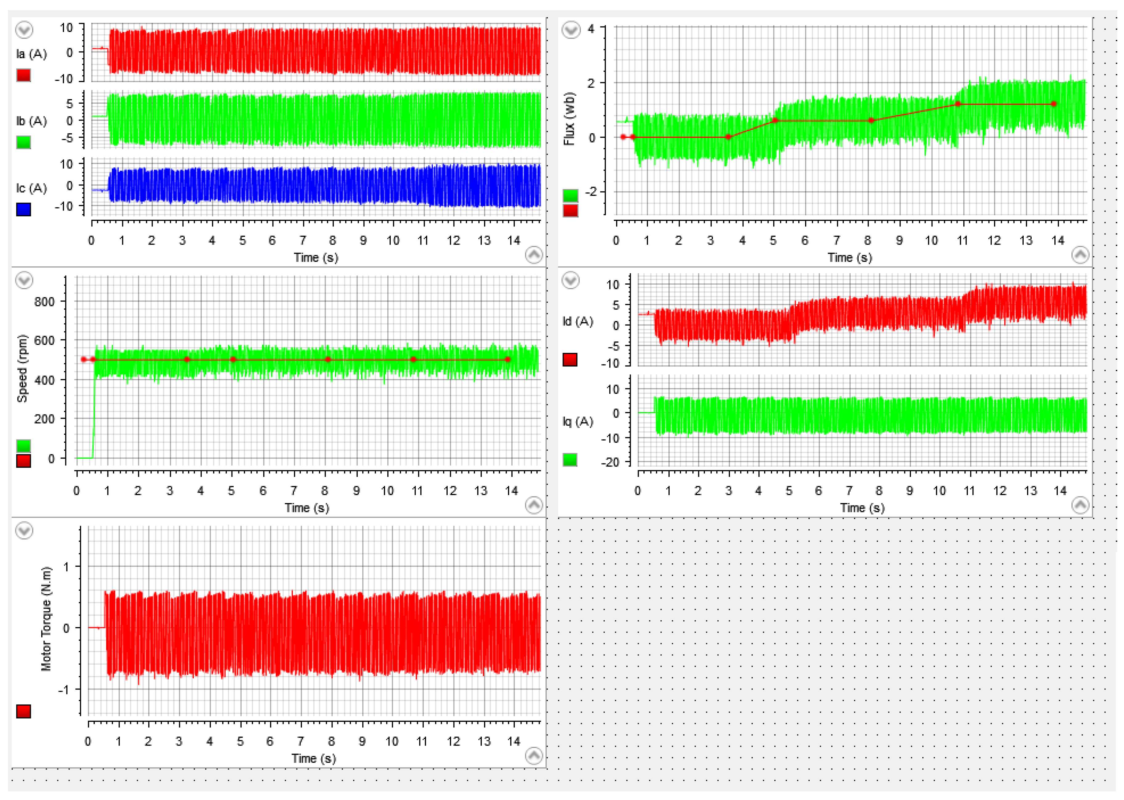
5.2. Case 2: Flux Change
5.3. Case 3: Load Change
5.4. Limitations of This Study and the Shortcomings of the Proposed Method
6. Conclusions
Author Contributions
Funding
Data Availability Statement
Conflicts of Interest
Nomenclature
| PMSM phase resistance | |
| Motor currents phases a, b, c | |
| motor current d-axis component | |
| motor current q-axis component | |
| voltage constant of PMSM | |
| integral component gain | |
| proportional component gain | |
| resonant component gain | |
| torque constant | |
| PMSM d-axis inductance |
| PMSM q-axis inductance | |
| p | number of pole pairs |
| the electromagnetic torque | |
| t | time |
| The stator voltage of PMSM in d-axis | |
| The stator voltage of PMSM in q-axis | |
| permanent magnetic flux linkage | |
| flux linkage of the stator in d-axis | |
| flux linkage of the stator in q-axis | |
| rotor angle position | |
| the fundamental angular frequency | |
| electrical rotor speed | |
| the natural frequency | |
| the damping ratio |
References
- Ghanayem, H.; Alathamneh, M.; Nelms, R.M. A comparative study of PMSM torque control using proportional-integral and proportional-resonant controllers. In Proceedings of the SoutheastCon 2022, Mobile, AL, USA, 26 March–3 April 2022; pp. 453–458. [Google Scholar]
- Stulrajter, M.; Hrabovcová, V.; Franko, M. Permanent Magnets Synchronous Motor Control Theory. J. Electr. Eng. 2007, 58, 79–84. [Google Scholar]
- Sakunthala, S.; Kiranmayi, R.; Mandadi, P.N. A Review on Speed Control of Permanent Magnet Synchronous Motor Drive Using Different Control Techniques. In Proceedings of the International Conference on Power, Energy, Control and Transmission Systems (ICPECTS), Chennai, India, 22–23 February 2018; pp. 97–102. [Google Scholar]
- Bida, V.M.; Samokhvalov, D.V.; Al-Mahturi, F.S. PMSM vector control techniques—A survey. In Proceedings of the IEEE Conference of Russian Young Researchers in Electrical and Electronic Engineering (EIConRus), Moscow/St. Petersburg, Russia, 29 January–1 February 2018; pp. 577–581. [Google Scholar]
- Abassi, M.; Khlaief, A.; Saadaoui, O.; Chaari, A.; Boussak, M. Performance analysis of FOC and DTC for PMSM drives using SVPWM technique. In Proceedings of the 16th International Conference on Sciences and Techniques of Automatic Control and Computer Engineering (STA), Monastir, Tunisia, 21–23 December 2015; pp. 228–233. [Google Scholar]
- Korkmaz, F.; Topaloğlu, I.; Çakir, M.F.; Gürbüz, R. Comparative performance evaluation of FOC and DTC controlled PMSM drives. In Proceedings of the 4th International Conference on Power Engineering, Energy and Electrical Drives, Istanbul, Turkey, 13–17 May 2013; pp. 705–708. [Google Scholar]
- Dwivedi, S.; Singh, B. Vector Control vs. Direct Torque Control comparative evaluation for PMSM drive. In Proceedings of the Joint International Conference on Power Electronics, Drives and Energy Systems & 2010 Power India, New Delhi, India, 20–23 December 2010; pp. 1–8. [Google Scholar]
- Yue, Y.; Zhang, R.; Wu, B.; Shao, W. Direct torque control method of PMSM based on fractional order PID controller. In Proceedings of the 6th Data Driven Control and Learning Systems (DDCLS), Chongqing, China, 26–27 May 2017; pp. 411–415. [Google Scholar]
- Gupta, N.P.; Gupta, P. Performance analysis of direct torque control of PMSM drive using SVPWM—Inverter. In Proceedings of the IEEE 5th India International Conference on Power Electronics (IICPE), Delhi, India, 6–8 December 2012; pp. 1–6. [Google Scholar]
- Tang, M.; Zhuang, S. On Speed Control of a Permanent Magnet Synchronous Motor with Current Predictive Compensation. Energies 2019, 12, 65. [Google Scholar] [CrossRef] [Green Version]
- Lyu, M.; Wu, G.; Luo, D.; Rong, F.; Huang, S. Robust Nonlinear Predictive Current Control Techniques for PMSM. Energies 2019, 12, 443. [Google Scholar] [CrossRef] [Green Version]
- Codreş, B.; Găiceanu, M.; Şolea, R.; Eni, C. Model predictive speed control of Permanent Magnet Synchronous Motor. In Proceedings of the International Conference on Optimization of Electrical and Electronic Equipment (OPTIM), Bran, Romania, 22–24 May 2014; pp. 477–482. [Google Scholar]
- Huang, X.; Pan, H.; Yuan, K. Speed and Current Control of PMSM based on Double MPC. In Proceedings of the 7th International Forum on Electrical Engineering and Automation (IFEEA), Hefei, China, 25–27 September 2020; pp. 300–304. [Google Scholar]
- Fang, L.; Yushun, W.; Ruiqi, W. Simulation of speed-control system for PMSM based on sliding mode control. In Proceedings of the International Conference on Mechatronic Sciences, Electric Engineering and Computer (MEC), Shenyang, China, 20–22 December 2013; pp. 52–56. [Google Scholar]
- Yan, L.; Dou, M.; Hua, Z. Disturbance Compensation-Based Model Predictive Flux Control of SPMSM with Optimal Duty Cycle. IEEE Emerg. Sel. Top. Power Electron. 2019, 7, 1872–1882. [Google Scholar] [CrossRef]
- Mohamed, Y.A. A Novel Direct Instantaneous Torque and Flux Control With an ADALINE-Based Motor Model for a High Performance DD-PMSM. IEEE Trans. Power Electron. 2007, 22, 2042–2049. [Google Scholar] [CrossRef]
- Dastjerdi, R.S.; Abbasian, M.A.; Saghafi, H.; Vafaie, M.H. Performance Improvement of Permanent-Magnet Synchronous Motor Using a New Deadbeat-Direct Current Controller. IEEE Trans. Power Electron. 2018, 34, 3530–3543. [Google Scholar] [CrossRef]
- Rubino, S.; Bojoi, I.R.; Armando, E.; Tenconi, A. Deadbeat direct flux vector control of surface permanent magnet motor drives. IEEE Trans. Ind. Appl. 2020, 56, 2685–2699. [Google Scholar] [CrossRef]
- Dai, S.; Wang, J.; Sun, Z.; Chong, E. Deadbeat predictive current control for high-speed PMSM drives with low switching-to-fundamental frequency ratios. IEEE Trans. Ind. Electron. 2021, 69, 4510–4521. [Google Scholar] [CrossRef]
- Sun, X.; Zhang, Y.; Lei, G.; Guo, Y.; Zhu, J. An improved deadbeat predictive stator flux control with reduced-order disturbance observer for in-wheel PMSMs. IEEE/ASME Trans. Mechatron. 2021, 27, 690–700. [Google Scholar] [CrossRef]
- Chen, J.; Wang, J.; Yan, B. Simulation Research on Deadbeat Direct Torque and Flux Control of Permanent Magnet Synchronous Motor. Energies 2022, 15, 3009. [Google Scholar] [CrossRef]
- Yun, D.; Kim, N.; Hyun, D.; Baek, J. Torque Improvement of Six-Phase Permanent-Magnet Synchronous Machine Drive with Fifth-Harmonic Current Injection for Electric Vehicles. Energies 2022, 15, 3122. [Google Scholar] [CrossRef]
- Ton, T.-D.; Hsieh, M.-F. A Deadbeat Current and Flux Vector Control for IPMSM Drive with High Dynamic Performance. Appl. Sci. 2022, 12, 3789. [Google Scholar] [CrossRef]
- Zhang, K.; Xie, Y.; Li, S.; He, Y. Vector Control of PMSM Based on Proportional Resonance Control. In Proceedings of the 6th Inter-national Conference on Systems and Informatics (ICSAI), Shanghai, China, 2–4 November 2019; pp. 51–56.
- Minghe, T.; Bo, W.; Yong, Y.; Xing, M.; Qinghua, D.; Dianguo, X. Proportional Resonant-Based Active Disturbance Rejection Control for Speed Fluctuation Suppression of PMSM Drives. In Proceedings of the 22nd International Conference on Electrical Machines and Systems (ICEMS), Harbin, China, 11–14 August 2019; pp. 1–6.
- Vujji, A.; Dahiya, R. Speed Estimator for Direct Torque and Flux Control of PMSM Drive using MRAC based on Rotor flux. In Proceedings of the IEEE 9th Power India International Conference (PIICON), Sonepat, India, 28 February–1 March 2020; pp. 1–6. [Google Scholar]
- Yunhao, P.; Dejun, Y.; Yansong, H. The stator flux linkage adaptive SVM-DTC control strategy of permanent magnet synchronous motor. In Proceedings of the 6th Asia Conference on Power and Electrical Engineering (ACPEE), Chongqing, China, 8–11 April 2021; pp. 826–831.
- Krause, P.C.; Wasynczuk, O.; Sudhoff, S.D.; Pekarek, S.D. Analysis of Electric Machinery and Drive Systems; Wiley-IEEE Press: Piscatawy, NJ, USA, 2013. [Google Scholar]
- Ziegler, J.G.; Nichols, N.B. Optimum Settings for Automatic Controllers. J. Dyn. Syst. Meas. Control 1993, 115, 220–222. [Google Scholar] [CrossRef] [Green Version]
- Alathamneh, M.; Ghanayem, H.; Yang, X.; Nelms, R.M. Three-Phase Grid-Connected Inverter Power Control under Unbalanced Grid Conditions Using a Proportional-Resonant Control Method. Energies 2022, 15, 7051. [Google Scholar] [CrossRef]
- Holmes, D.G.; Lipo, T.A.; McGrath, B.P.; Kong, W.Y. Optimized Design of Stationary Frame Three Phase AC Current Regulators. IEEE Trans. Power Electron. 2009, 24, 2417–2426. [Google Scholar] [CrossRef]


| Parameter | Value |
|---|---|
| Rated power | 200 W |
| Rated voltage | 42 V |
| Max speed | 3000 RPM |
| Pole-pairs number | 4 |
| Voltage constant | 9.5 V/Krpm |
| Resistance (L-L) | 0.4 Ohms |
| Inductance (L-L) | 540 H |
| Magnetic flux linkage | 0.01309 Wb |
| Speed | Flux | Currents | |
|---|---|---|---|
| Controller gains | |||
Disclaimer/Publisher’s Note: The statements, opinions and data contained in all publications are solely those of the individual author(s) and contributor(s) and not of MDPI and/or the editor(s). MDPI and/or the editor(s) disclaim responsibility for any injury to people or property resulting from any ideas, methods, instructions or products referred to in the content. |
© 2023 by the authors. Licensee MDPI, Basel, Switzerland. This article is an open access article distributed under the terms and conditions of the Creative Commons Attribution (CC BY) license (https://creativecommons.org/licenses/by/4.0/).
Share and Cite
Ghanayem, H.; Alathamneh, M.; Nelms, R.M. Decoupled Speed and Flux Control of Three-Phase PMSM Based on the Proportional-Resonant Control Method. Energies 2023, 16, 1053. https://doi.org/10.3390/en16031053
Ghanayem H, Alathamneh M, Nelms RM. Decoupled Speed and Flux Control of Three-Phase PMSM Based on the Proportional-Resonant Control Method. Energies. 2023; 16(3):1053. https://doi.org/10.3390/en16031053
Chicago/Turabian StyleGhanayem, Haneen, Mohammad Alathamneh, and R. M. Nelms. 2023. "Decoupled Speed and Flux Control of Three-Phase PMSM Based on the Proportional-Resonant Control Method" Energies 16, no. 3: 1053. https://doi.org/10.3390/en16031053