Article

High-Precision Switched Capacitor Device with an Energy Estimation Circuit

1
Department of Measurement Science, Electronics and Control, Silesian University of Technology (SUT), 44-100 Gliwice, Poland
2
KDE Electronic Construction and Design, 44-335 Jastrzębie-Zdrój, Poland
*
Author to whom correspondence should be addressed.
Energies 2023, 16(3), 1086; https://doi.org/10.3390/en16031086
Submission received: 10 November 2022 / Revised: 27 December 2022 / Accepted: 14 January 2023 / Published: 18 January 2023
(This article belongs to the Special Issue Intelligent Control for Future Systems)

Abstract

:
This article introduces a device for the precise testing of the non-linearities of inductive voltage dividers and digitizers used in digital impedance bridges. The device is based on switched capacitors composed of an NP0 dielectric, in addition to high-quality microwave relays. The article discusses issue concerning the symmetrization of the device as one of the main ways to achieve a high accuracy. Furthermore, a temperature-stabilization system for the device is presented. The system uses a battery management system to estimate the quantity of the energy available in the supply battery. The article further discusses problems encountered with the design of heating elements, which are situated on a laminate with an aluminum substrate.

1. Introduction

In recent years, digital impedance comparison systems have undergone rapid development [1,2,3,4,5,6,7,8,9]. Although the National Metrology Institutes (NMIs) of highly developed countries implement impedance bridges based on quantum phenomena [1,2], the NMIs of less developed countries primarily focus on the development of comparator bridges using digital, non-quantum AC voltage sources [3,4,5,6,7,8,9,10,11]. Such comparators are popular because they are characterized by a relatively low price, short measurement times, ease of use, and the ability to compare any impedance standards in an entire complex plane. Digital impedance bridges of this type can achieve a comparison uncertainty of 10−6 [12]. Two groups of such comparators exist. The first includes systems in which the ratio arms are two AC voltage sources with a known complex voltage ratio determined using a quantum or digital signal source [3,6,7,8,9]. The second group includes systems in which the complex voltage ratio is determined by sampling the voltages in the ratio arms with an appropriate digitizer, such as a PXI-4461 device [13,14,15].
Some of the most common errors within circuits with digital voltage sources are those that result from the non-linearity of either the source or the digitizer, depending on the type of bridge. Comprehensive analyses of the nonlinearity errors are given in [16,17], which proved that the negative effects of nonlinearity errors are particularly pronounced when comparing impedances with significantly different moduli, such as a ratio of 10:1. As demonstrated in [16], nonlinearity errors of a source or digitizer can reach several μΩ/Ω in practical applications, which is unacceptable in the dedicated systems of national metrological institutes. The accuracy of measuring impedances that contrast in this manner can be improved by measuring the non-linearity errors of the source or digitizer used and by introducing appropriate correction factors in the software of the comparison system to correct the measured complex voltage ratio. This solution is intended to be applied to the sampling digital impedance bridge currently being developed at the Silesian University of Technology (SUT) in Gliwice, Poland. This system must be capable of precisely reproducing voltage or impedance ratios of 1:n with an accuracy of 10−7–10−8. Two possible methods can be used for reproducing the reference voltage or impedance ratio: (1) the usage of a standard multi-decade inductive voltage divider (IVD), such as a Dekatran DT-72A or a Tinsley 5560J, or (2) the usage of the permutation method with switchable capacitors [18,19,20] or the capacitance scaling method (the so-called capacitance build-up method) [21]. The former method was used by the authors for the investigation of digitizers’ nonlinearity [22], but its accuracy is limited by the calibration uncertainty of the inductive voltage divider. This uncertainty may be at a level 10−6 for frequencies higher than 1 kHz. The latter approach is particularly useful because it allows one to obtain an accuracy of hundred times higher than that of the IVD method, so it can be used to calibrate an inductive divider with uncertainties below 10−8 [20]. Hence, the objective of this paper was to design and manufacture a dedicated device with switchable capacitors that implement a permuting method to reproduce a reference impedance ratio.
The remainder of this paper is organized as follows. Section 2.1 describes the device concept, and Section 2.2 details the construction of the switched module. Section 2.4 further discusses issues concerning the thermoregulation of the developed device, which is extremely important for such a measuring instrument. Section 2.5 describes the battery management system (BMS), which is used to estimate the quantity of energy stored in the battery and to predict the operating time of the thermostat when powered by the battery. Moreover, the estimation of the battery model equivalent parameters is discussed, and the circuit used to determine them is presented. Finally, Section 3 concludes the paper.

2. Switched Capacitor Device

2.1. Device Concept

The theoretical basis of the permutation method has been known for over 60 years [20]. The method is based on a system of capacitors with as equal capacitance values as possible. The number of capacitors depending on the required impedance ratio can be connected in parallel to form a voltage divider, which is shown in the right part of Figure 1. For example, to obtain a n:1 ratio (where n = 1, …, 10), eleven capacitors are required. In a bridge circuit that is created by connecting two sources (E1 and E2) and a DET null detector to the capacitance divider, one of the capacitors is situated within the lower arm of the bridge and the other is situated within the upper arm. The first capacitor in the upper arm is then shifted to the lower arm (see arrows in Figure 1)m and the capacitor that was previously connected in the lower arm of the bridge goes to the last position in the upper arm. This permutation sequence is repeated 11 times to allow each capacitor to pass through the lower arm of the bridge. The theoretical basis of the method is that the voltage ratio errors—corresponding to the deviation of each capacitance from the nominal value—are averaged by the cyclic shifting of the capacitors. Hence, the more accurately the voltage ratio is reproduced, the smaller the deviation of the capacitance values from the average value.
A block diagram of the switched capacitor device is shown in Figure 2. The central section of the device is the switched capacitor module (SCM), the electrical diagram of which is presented in Figure 3. The SCM consists of 11 identical branches in which the 11 capacitors are situated. The capacitors must have very similar capacitance and dissipation factor (tgδ) values. Moreover, the capacitors should have the smallest possible temperature coefficient, the low dissipation factor, and good long-term stability. The other device components are a relay controller, a temperature-stabilization system, and an advanced power supply system with energy backup. Each of these elements is described in the following sections.

2.2. Construction of the SCM

The experience of this paper’s authors suggested that NP0 (C0G) dielectric capacitors were the most suitable for constructing a precise and stable SCM device (Figure 3). Such an NP0 dielectric is the most popular formulation of the temperature-compensating EIA Class I ceramic materials. Modern NP0 formulations contain neodymium, samarium, and other rare earth oxides, and NP0 ceramics are among the most stable capacitor dielectrics available. Such capacitors display temperature-dependent changes in capacitance of 0 ± 30 ppm/°C. The capacitance drift (hysteresis) for NP0 ceramics is less than ±0.05%, while that for films reaches up to ±2%. The capacitance change for NP0 capacitors is typically less than ±0.1% over their lifetime, one-fifth of that shown by most other dielectrics. Moreover, NP0 formulations display no aging characteristics. Due to these characteristics, the use of NP0 capacitors was chosen for the project, and 200 Murata (Japan) capacitors (GRM42-6COG101J50) were purchased. The capacitors had a nominal value of 100 pF. Of the 200 capacitors, the 11 capacitors with the most similar capacitance and dissipation factor values were selected. The capacitances and dissipation factors were measured at the Polish National Metrology Institute (GUM) in Warsaw using an RLC GenRad 1689 bridge. The measurement results are given in Table 1.
The standard deviations of the capacitance and dissipation factor for the 11 selected capacitors were 0.03 pF and 0.3 × 10⁻⁵, respectively.
The solution presented in [17] addresses problems caused by the influence of parasitic capacitances that arise due to the connections of the capacitors to the measurement paths. Therefore, the developed mechanical structure was given the greatest possible symmetry to reduce the impact of such parasitic capacitances within the measurement system. As shown in Figure 4, each capacitor is situated within a separate cell. Each cell is entirely isolated other than the leads connecting the capacitor electrodes with the relays and with the common terminal. Each individual capacitor can be connected to the high-potential (HP), high-current (HC), low-potential (LP), and low-current (LC) paths via one of eleven high-quality microwave relays (Figure 4). The use of four coaxial lines—the four-terminal-pair method—produces the highest accuracy and greatest immunity to electromagnetic interference [5,7,12]. The relay control elements are situated outside of the housing to act as a screen. Figure 4a shows a 3D model of the SCM with the printed circuit board (PCB) containing the relays. The capacitors in each of the individual branches are connected to the central pins of the SMA sockets, arranged within a ring-shaped housing. Figure 4b shows a photograph of the assembled SCM.

2.3. Relay Controller

The developed switched capacitor device is a component of the digital sampling impedance bridge described in [9] and must cooperate with a PXI system. Hence, a National Instruments PXI NI-2567 board was chosen to be used for the ultimate control of the relays. The SCM relays are controlled by an intermediatory circuit that is composed of discrete elements. The circuit contains a set of transistors that supply an appropriately polarized voltage to the bistable single-coil relays in accordance with the control signals provided by the PXI-2567 board. The system was designed such that if commands to simultaneously switch on and switch off a specific relay are erroneously sent, then the relay is automatically switched off.

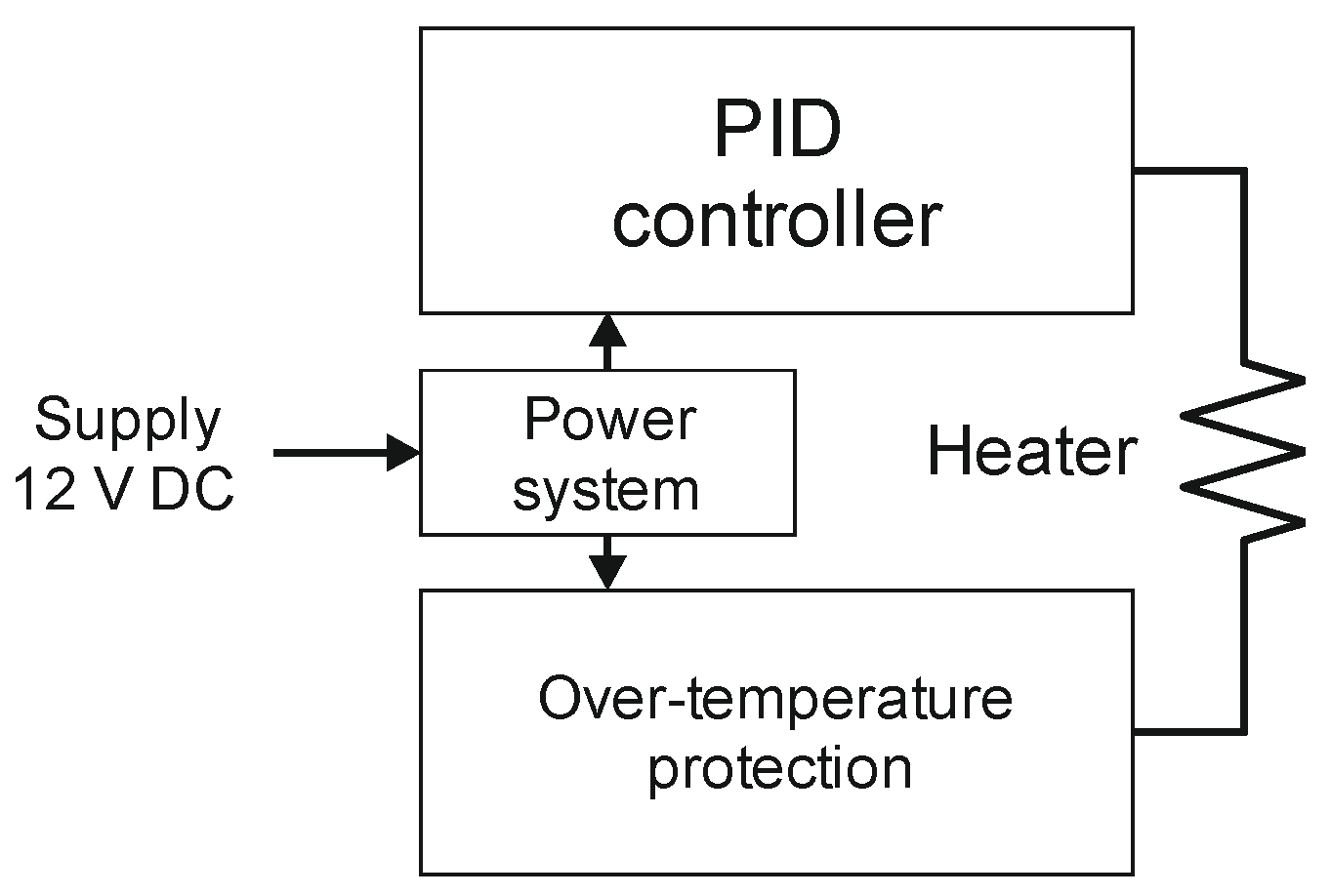
2.4. The Temperature-Stabilization System

Temperature is among the environmental parameters that have the most significant impact on the properties of measuring tools—particularly those that must be highly accurate, such as measurement standards or calibrators. The maintenance of a constant temperature is referred to as thermoregulation, and the devices that are used to accomplish this are known as thermostats. Thermoregulation is intended to not only reduce the drift or temperature instability caused by changes in the ambient temperature but also to reduce the influence of temperature hysteresis. This latter phenomenon is especially influential when assessing electrical quantity standards, particularly the assessment of DC voltage standards using subsurface Zener diodes. The regulation of the temperature of the impedance standards is equally important, particularly those standards that have relatively high temperature coefficients of up to 35 ppm/°C [23].
The designed switched capacitor device is thermoregulated, as is appropriate for a system that calibrates precise measuring equipment. The device accuracy directly depends on the stability of the capacitance of the capacitors throughout the measurement cycle. To reduce the influence of ambient temperature changes on the capacitor parameters, a custom temperature-stabilization system is provided. The primary component of the system is a heating element that generates thermal energy when provided with electric current. Early examples of thermostats used in measuring instruments contained a heating element in the form of resistance wire—such as Kanthal wire—or power resistors of several watts in size, placed inside flat aluminum bars directly screwed onto the PCB. Such constructions are somewhat complex, and they are characterized by relatively large physical dimensions including weight. Therefore, the authors of this work chose to develop a system in which the thermostats are integrated with the heating element and constructed from readily available and relatively cheap copper laminates on an aluminum substrate. The heating element of such a thermostat is composed of arced copper paths. The PCB for such a thermostat can be designed using standard PCB design software. The technology required to construct such a circuit is commonly available to companies that produce custom PCBs, and the cost of the circuit is relatively low.
Before developing the specific thermostat required for the switched capacitor device, the authors investigated several different integrated thermostats on a copper laminate with an aluminum substrate. The obtained heater resistance for each system substantially deviated from the assumed value. Moreover, the obtained resistance was always greater than the intended value. This discrepancy was caused during the process of producing printed circuits on laminates with an aluminum substrate: the shape of the resultant path cross-sections was not rectangular but trapezoidal. This effect was caused by the undercutting of the sides of each path. Additionally, during the initial production of the PCBs, the copper layer was cleaned with brushes, reducing its thickness from a typical value of 35 µm. PCB manufacturers are typically reluctant to modify this technological process, so the study authors designed the heating element in such a manner that the obtained resistance value was close to the desired value. For this purpose, several variants of the heating element were designed and the resistances of the PCB paths was measured. This approach allowed the relative change in the heater resistance to be estimated in relation to the desired value. Moreover, the measured value was found to strongly depend upon the number of arced paths of the heater and the arc radius ® (Figure 5). A greater number of arcs and a greater radius correspond with a greater relative change in resistance.
Table 2 summarizes the parameters of the heating element paths for three physical models of thermostat PCBs.
Based on the obtained results, the average value of path resistance increase in relation to the desired value was estimated to be 38%. Therefore, for the final heater design, a resistance error of this value was assumed. Figure 6 shows a prototype PCB with an integrated thermostat designed for use with the switched capacitor device.
Figure 7 shows a block diagram of the temperature-stabilization system of the thermostat. The system is based on a precise analog PID controller operating in a linear (continuous) mode. This mode provides a significant reduction in electromagnetic disturbance that is capable of penetrating the measurement system. A key element of the thermoregulator is a bridge circuit with a ratio arm that integrates precise DC voltage sources.
The operating temperature of the heater can be modified by changing the value of the resistor located in the passive arm of the bridge. The arm also houses an SMD Pt100 temperature sensor. The sensor is directly soldered to the copper contact fields on the surface of the thermostat PCB, which ensures the good thermal contact of the sensor with the thermostat substrate. The stabilized temperature value was set to approximately 28 °C. The temperature-stabilization system protects against excessive temperature increases by disconnecting the heater from the supply voltage if the temperature exceeds 45 °C. The thermostat is supplied with DC voltage in the range of 11 to 14 V. As shown in Figure 6, the analog temperature-stabilization system is situated in the central part of the PCB.
To reduce both the influence of ambient temperature changes on the thermoregulated board and the thermostat energy consumption, the board is thermally insulated with extruded polystyrene insulation. The insulation is formed to the required shape with the use of a numerically controlled CNC milling machine. The material has very good insulating properties: a board of thickness 5 cm has a thermal conductivity coefficient of λD < 0.033 W/(m·K) and thermal resistance of RD = 1.5 m2·K/W. The insulated module is then sited within an aluminum chassis that acts as an additional screen and provides structural support for the insulation. Figure 8 shows the insulated SCM situated within the aluminum chassis. Each device terminal is constructed from metrology-grade MUSA connectors, which are commonly used in contemporary high-accuracy impedance metrology.

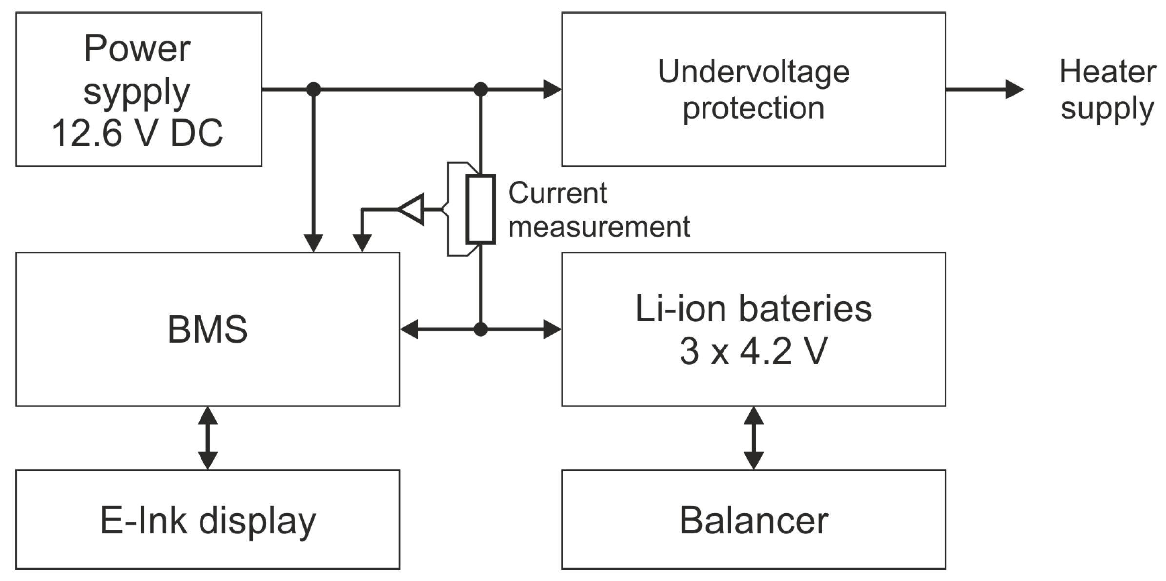
2.5. Power Supply—BMS and Power Setup

The SCM temperature-stabilization system is equipped with a battery backup for scenarios in which the thermostat cannot be supplied from the power grid, such as during transportation. The BMS system is used to monitor and estimate the quantity of available energy within the lithium-ion battery used by the switched capacitor device. A block diagram of the BMS is shown in Figure 9. The system uses an Analog Devices ADuCM362 microcontroller that is equipped with a 24-bit analog-to-digital converter and a 16-bit digital-to-analog converter. The analog-to-digital converter measures the input voltage of the system and the voltage across individual cells of the battery. In addition, the analog-to-digital converter measures the current flowing through the battery and the temperature of both the battery and the heater. The digital-to-analog converter is used to correct the zero-shift error that occurs when measuring the current. The measurement results are displayed on an E-Ink display with ultra-low energy consumption.
The microcontroller contains an algorithm for estimating the energy available within the battery. The algorithm, described in detail in [24,25], calculates the state of charge of the battery on the basis of the voltages across each cell and the current flowing through the battery. In this manner, the algorithm can predict the system operation time during battery operation. Figure 10 shows a prototype of the BMS system used in the switched capacitor device.
The BMS also acts as a protection system against the excessive discharge of the battery that supplies the heater. When the voltage across the battery pack terminals falls below 9.6 V, the power to the thermostat is deactivated. This state persists until the battery is charged to a voltage of at least 11.6 V. The battery pack contains nine NCR18650GA lithium-ion cells connected in a three-series–three-parallel configuration. The electrodes of the individual cells are welded to one another using a professional welding machine. The cells are situated within a custom insulating housing constructed using 3D printing technology.
The battery pack is protected by a protection system with a balancer dedicated for use with lithium-ion batteries. The balancer is required to maintain an identical voltage at the terminals of each of the individual cells of the battery pack during charging in order to extend their service life. In addition, the balancer protects the battery pack against excessive discharge and limits the maximum current that can be drawn from the battery during scenarios such as an unintentional short-circuit of the battery terminals.

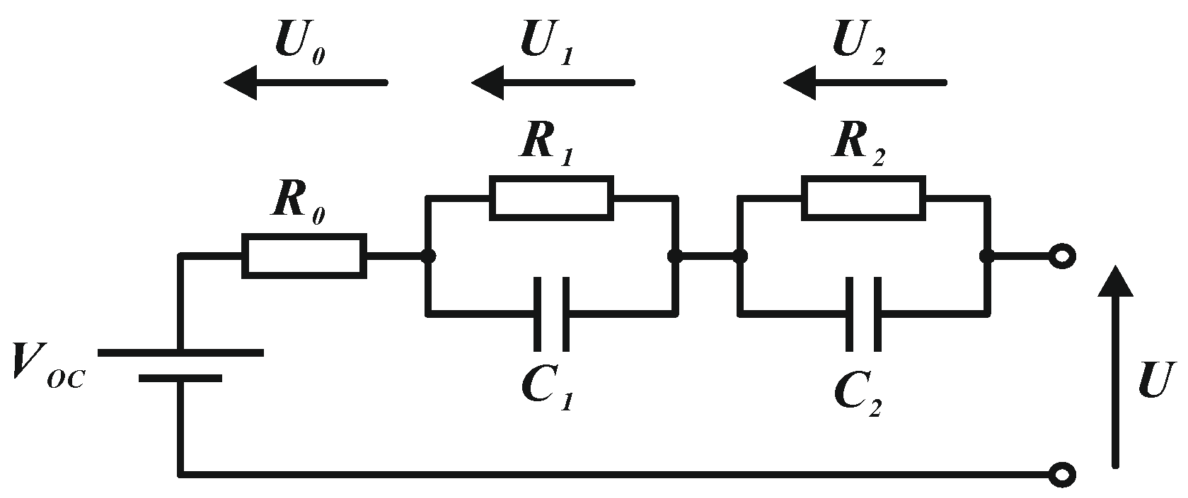
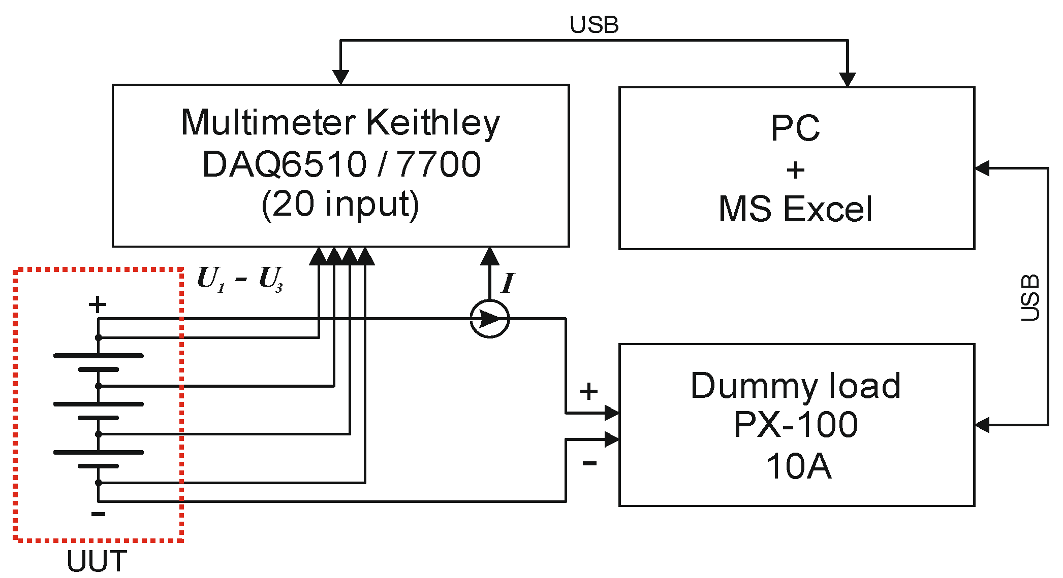
Battery Energy Estimation Algorithm

The algorithm used to estimate the energy available within the battery is based on adaptive extended Kalman filtering (AEKF) [24,25]. For the algorithm to correctly function, the parameters of the equivalent diagram of the lithium-ion battery model (Figure 11) must be identified. The identification process includes the determination of the parameters R0, R1, C1, R2, and C2, in addition to the form of a nonlinear function describing the voltage source VOC (SOC). Parameter identification is required because the AEKF covariance parameters are not set as constants but are adaptively updated with each cycle of the algorithm using a dedicated SOC estimator [26,27,28].
The above elements of the equivalent diagram were determined using the measurement system shown in Figure 12. The system consists of a Keithley DAC6510 multimeter, a digitally controlled dummy load, and a PC that controls the measurement of individual cell voltages, the total voltage, and the current drawn from the battery. The control program was written in Visual Basic for Applications using the Keysight IO Libraries Suite.
Measurements were obtained at three different battery temperatures: 5 °C, 25 °C, and 45 °C. The collected data, the voltages of each cells of batteries U1–U3 and load current I, were used to estimate the parameters for each temperature value. The estimation was conducted using MATLAB software. Figure 13 shows the estimated values of VOC(SOC), R0(SOC), R1(SOC), C1(SOC), R2(SOC) and C2(SOC) for a temperature of 25 °C. Since the voltages for each battery cell were measured and the coefficients were determined for these data, the final average value was calculated for each SOC point. The obtained data, in the form of tabulated coefficients, were entered into BMS system software. The software was written in the C language in the Keil environment for ARM microcontrollers with a Cortex-M core. The AEKF estimation algorithm was generated with MATLAB software version R2021a.

3. Conclusions

This paper presents a system for the precise testing of the nonlinearities of inductive voltage dividers and digitizers used in digital impedance bridges. The described system is characterized by a fully symmetrical structure that incorporates interference-free techniques such as the isolation of interference-generating elements, the elimination of inductive couplings, and the use of good magnetic and electrical shielding. The symmetry of the structure reduces the influence of parasitic capacitances for all possible combinations of capacitor switching in the individual branches of the circuit. The critical elements of the system are situated within a bespoke integrated thermostat. The use of the thermostat within the presented system is universal and can also be used to stabilize the temperature of standards and the critical subsystems of measuring devices. A BMS system is used to estimate the quantity of energy stored within the battery and to predict the operating time of the thermostat when being powered by the battery. The parameters of the battery necessary for the proper operation of the BMS were determined in a real measurement system using the collected data and an algorithm based on adaptive extended Kalman filters. The MUSA coaxial connectors used in the device facilitate the operation of the device within digital impedance bridges. In future work, the metrological properties of the device will be investigated, and the device will be used to measure the nonlinearity errors of digitizers used at the GUM and SUT. The integration of the switched capacitor device with an impedance comparison system will contribute to the extension of the measurement capabilities of the Polish National Metrology Institute and an increase in the accuracy of the institute’s impedance comparison.

Author Contributions

Conceptualization, K.M. and K.D.; methodology, K.D.; software, K.D.; investigation, K.M. and K.D.; resources, M.K.; writing—original draft preparation, K.M.; writing—review and editing, M.K.; visualization, K.D.; supervision, M.K.; project administration, K.M.; funding acquisition, K.M. All authors have read and agreed to the published version of the manuscript.

Funding

This research was partially funded by the Polish National Science Center (NCN) (grant No. 2020/37/B/ST7/00057). This work was partially supported by the Rector of Silesian University of Technology (postdoctoral (habilitation) grant No. 05/020/RGH21/0062).

Data Availability Statement

The data presented in this study are available on request from the corresponding author.

Acknowledgments

The authors acknowledge the considerable contribution the team from the Central Office of Measures (GUM) in Warsaw, Poland, made by performing measurements of SMD capacitors using an AH 27000A bridge.

Conflicts of Interest

The authors declare no conflict of interest. The funders had no role in the design of the study; in the collection. analyses. or interpretation of data; in the writing of the manuscript; or in the decision to publish the results.

References

  1. Overney, F.; Flowers-Jacobs, N.E.; Jeanneret, B.; Rüfenacht, A.; Fox, A.E.; Dresselhaus, P.D.; Benz, S.P. Dual Josephson impedance bridge: Towards a universal bridge for impedance metrology. Metrologia 2020, 57, 065014. [Google Scholar] [CrossRef]
  2. Overney, F.; Flowers-Jacobs, N.E.; Jeanneret, B.; Rüfenacht, A.; Fox, A.E.; Underwood, J.M.; Koffman, A.D.; Benz, S.P. Josephson-based full digital bridge for high-accuracy impedance comparisons. Metrologia 2016, 53, 1045–1053. [Google Scholar] [CrossRef]
  3. Callegaro, L.; D’Elia, V.; Kampik, M.; Kim, D.B.; Ortolano, M.; Pourdanesh, F. Ngoc Thanh Mai Tran, Experiences with a two terminal-pair digital impedance bridge. IEEE Trans. Instrum. Meas. 2015, 64, 1460–1465. [Google Scholar] [CrossRef] [Green Version]
  4. Miroslaw, M.; Kaczmarek, J.; Rybski, R. Characterization of PXI-Based Generators for Impedance Measurement Setups. IEEE Trans. Instrum. Meas. 2019, 68, 1806–1813. [Google Scholar] [CrossRef]
  5. Kučera, J.; Kováč, J. A reconfigurable four terminal-pair digitally assisted and fully digital impedance ratio bridge. IEEE Trans. Instrum. Meas. 2018, 67, 1199–1206. [Google Scholar] [CrossRef]
  6. Ortolano, M.; Palafox, L.; Kucera, J.; Callegaro, L.; D’Elia, V.; Marzano, M.; Overney, F.; Gulmez, G. An international comparison of phase angle standards between the novel impedance bridges of CMI, INRIM and METAS. Metrologia 2018, 55, 499–512. [Google Scholar] [CrossRef] [Green Version]
  7. Mašláň, S.; Šíra, M.; Skalická, T.; Bergsten, T. Four-Terminal Pair Digital Sampling Impedance Bridge up to 1 MHz. IEEE Trans. Instrum. Meas. 2019, 68, 1860–1869. [Google Scholar] [CrossRef]
  8. Overney, F.; Jeanneret, B. RLC Bridge based on an Automated Synchronous Sampling System. IEEE Trans. Instrum. Meas. 2011, 60, 2393–2398. [Google Scholar] [CrossRef]
  9. Musioł, K.; Kampik, M.; Koszarny, M. A new sampling based four-terminal-pair digital impedance bridge. Meas. Sens. 2021, 18, 100307. [Google Scholar] [CrossRef]
  10. Musioł, K.; Kampik, M. Metrological triangles in impedance comparisons. Measurement 2019, 148, 106908. [Google Scholar] [CrossRef]
  11. Musioł, K.; Kampik, M. Investigations of the high-performance source of digitally synthesized sinusoidal voltage for primary impedance metrology. Measurement 2021, 168, 108308. [Google Scholar]
  12. Awan, S.; Kibble, B.; Schurr, J. Coaxial Electrical Circuits for Interference-Free Measurements (Electrical Measurement); IET: Edison, NJ, USA, 2010. [Google Scholar]
  13. Rybski, R.; Kaczmarek, J.; Koziol, M. A PXI-Based Calibration System for Low-Value AC Resistors. IEEE Trans. Instrum. Meas. 2018, 67, 905–911. [Google Scholar] [CrossRef]
  14. Rybski, R.; Kaczmarek, J.; Koziol, M. A High-Resolution PXI Digitizer for a Low-Value-Resistor Calibration System. IEEE Trans. Instrum. Meas. 2013, 62, 1783–1788. [Google Scholar] [CrossRef]
  15. Musioł, K.; Kampik, M. Calibration of PXI Data Acquisition Cards Used for Primary Impedance Metrology; Measurement systems in theory and practice; University of Zielona Góra: Zielna Góra, Poland, 2020; pp. 159–171. [Google Scholar]
  16. Ortolano, M.; Marzano, M.; D’Elia, V.; Tran, N.T.M.; Rybski, R.; Kaczmarek, J.; Koziol, M.; Musiol, K.; Christensen, A.E.; Callegaro, L.; et al. A Comprehensive Analysis of Error Sources in Electronic Fully Digital Impedance Bridges. IEEE Trans. Instrum. Meas. 2020, 70, 1–14. [Google Scholar] [CrossRef]
  17. Ortolano, M.; Marzano, M.; D’Elia, V.; Tran, N.T.M.; Rybski, R.; Kaczmarek, J.; Kozioł, M.; Musioł, K.; Christensen, A.; Pokatilov, A.; et al. Error sources in electronic fully-digital impedance bridges. In Proceedings of the 2020 Conference on Precision Electromagnetic Measurements (CPEM), Denver, CO, USA, 24–28 August 2020; pp. 1–2. [Google Scholar]
  18. Hsu, J.; Gong, J.; Huang, C. An automated permuting capacitor device for calibration of IVDs. IEEE Trans. Instrum. Meas. 2014, 63, 2271–2278. [Google Scholar] [CrossRef]
  19. Waltrip, B. A Programmable Capacitor for Inductance Measurements. IEEE Trans. Instrum. Meas. 2017, 66, 1572–1578. [Google Scholar] [CrossRef]
  20. Cutkosky, R.D.; Shields, J.Q. The Precision Measurement of Transformer Ratios. IRE Trans. Instrum. 1960, 9, 243–250. [Google Scholar] [CrossRef]
  21. Tran, N.T.M.; D’Elia, V.; Callegaro, L.; Ortolano, M. A Capacitance Build-up Method to Determine LCR Meter Errors and Capacitance Transfer. IEEE Trans. Instrum. Meas. 2020, 69, 5727–5735. [Google Scholar] [CrossRef]
  22. Musioł, K. Experimental Study of Digitizers Used in High-Precision Impedance Measurements. Energies 2022, 15, 4051. [Google Scholar] [CrossRef]
  23. IET Labs. 1482 Specification. Available online: https://www.ietlabs.com/pdf/Datasheets/1482.pdf (accessed on 28 September 2022).
  24. Guo, Y.; Zhao, Z.; Huang, L. SoC Estimation of Lithium Battery Based on AEKF Algorithm. In Proceedings of the 8th International Conference on Applied Energy, ICAE2016, Beijing, China, 8–11 October 2016. [Google Scholar]
  25. Pang, H.; Zhang, F. Experimental Data-Driven Parameter Identification and State of Charge Estimation for a Li-Ion Battery Equivalent Circuit Model. Energies 2018, 11, 1033. [Google Scholar] [CrossRef] [Green Version]
  26. He, H.; Xiong, R.; Zhang, X.; Sun, F.; Fan, J. State-of-Charge Estimation of the Lithium-Ion Battery Using an Adaptive Extended Kalman Filter Based on an Improved Thevenin Model. IEEE Trans. Veh. Technol. 2011, 60, 1461–1469. [Google Scholar]
  27. Charkhgard, M.; Farrokhi, M. State-of-charge estimation for lithium-ion batteries using neural networks and EKF. IEEE Trans. Ind. Electron. 2010, 57, 4178–4187. [Google Scholar] [CrossRef]
  28. Taborelli, C.; Onori, S. State of charge estimation using extended Kalman filters for battery management system. In Proceedings of the IEEE International Electric Vehicle Conference (IEVC), Florence, Italy, 17–19 December 2014; pp. 1–8. [Google Scholar]
Figure 1. A scheme presenting idea of the permuting capacitors.
Energies 16 01086 g001
Figure 2. Block diagram of the switched capacitor device.
Energies 16 01086 g002
Figure 3. Circuit diagram of the SCM.
Energies 16 01086 g003
Figure 4. Switched capacitor module (SCM): (a): a 3D model; (b): photograph.
Energies 16 01086 g004
Figure 5. An example of the arced paths of the copper heating element of the thermostat, with the arc radius (r) indicated.
Energies 16 01086 g005
Figure 6. A PCB with integrated thermostat designed for use with the switched capacitor device.
Energies 16 01086 g006
Figure 7. A block diagram of the temperature-stabilization system.
Energies 16 01086 g007
Figure 8. A photograph of the SCM showing the thermal insulation and the aluminum chassis.
Energies 16 01086 g008
Figure 9. A block diagram of the BMS.
Energies 16 01086 g009
Figure 10. A prototype of the BMS system used in the switched capacitor device.
Energies 16 01086 g010
Figure 11. The equivalent diagram of the lithium-ion battery model.
Energies 16 01086 g011
Figure 12. A block diagram of the measurement setup.
Energies 16 01086 g012
Figure 13. Results of battery parameter estimation.
Energies 16 01086 g013
Table 1. Values of the capacitors used in the SCM. The uncertainty of the capacitance measurements was 0.05%.
ItemCapacitance C
pF
Dissipation
Factor tgδ
× 10−5
1101.405.5
2101.405.4
3101.405.2
4101.425.6
5101.435.1
6101.435.7
7101.446.1
8101.455.5
9101.465.8
10101.476.0
11101.485.7
Table 2. A comparison of the desired and measured resistances for arced paths with h = 0.035 mm.
Length of the Meander
(mm)
Path Width
a
(mm)
Projected (Desired) Resistance
(Ω)
Measured (Real) Resistance
(Ω)
Relative Error of the Resistance
(%)
10,611.40.25420.427.133%
14,045.20.1838.054.543%
19,774.50.3131.142.838%
Disclaimer/Publisher’s Note: The statements, opinions and data contained in all publications are solely those of the individual author(s) and contributor(s) and not of MDPI and/or the editor(s). MDPI and/or the editor(s) disclaim responsibility for any injury to people or property resulting from any ideas, methods, instructions or products referred to in the content.

