Article

Deflagration-to-Detonation Transition in a Semi-Confined Slit Combustor Filled with Nitrogen Diluted Ethylene-Oxygen Mixture

by
Igor O. Shamshin
1,
Vladislav S. Ivanov
1,
Viktor S. Aksenov
1,2,
Pavel A. Gusev
1 and
Sergey M. Frolov
1,2,*
1
Department of Combustion and Explosion, Semenov Federal Research Center for Chemical Physics, 119991 Moscow, Russia
2
Institute of Laser and Plasma Technologies, National Research Nuclear University MEPhI, 115409 Moscow, Russia
*
Author to whom correspondence should be addressed.
Energies 2023, 16(3), 1098; https://doi.org/10.3390/en16031098
Submission received: 30 December 2022 / Revised: 11 January 2023 / Accepted: 18 January 2023 / Published: 19 January 2023

Abstract

:
The conditions for the mild initiation of the detonation of homogeneous stoichiometric ethylene-oxygen mixtures diluted with nitrogen up to ~40%vol. in a planar semi-confined slit-type combustor with a slit 5.0 ± 0.4 mm wide, simulating the annular combustor of a Rotating Detonation Engine (RDE), are determined experimentally using self-luminous high-speed video recording and pressure measurements. To ensure the mild detonation initiation, the fuel mixture in the RDE combustor must be ignited upon reaching a certain limiting (minimal) fill with the mixture and the arising flame must be transformed to a detonation via deflagration-to-detonation transition (DDT). Thus, for mild detonation initiation in a C2H4 + 3O2 mixture filling the slit, the height of the mixture layer must exceed the slit width by approximately 10 times (~50 mm), and for the C2H4 + 3(O2 + 2/5 N2) mixture, by approximately 60 times. The limiting height of the mixture layer required for DDT exhibits a sharp increase at a nitrogen-to-oxygen mole ratio above 0.25. Compared to the height of the detonation waves continuously rotating in the RDE combustor in the steady-state operation mode, for a mild start of the RDE, the fill of the combustor with the explosive mixture to a height of at least four times more is required.

1. Introduction

The combustor of a rocket or ramjet rotating detonation engine (RDE) is an annular gap between the outer wall and the central body [1,2]. When starting the engine, the annular gap is first filled with the fuel mixture, and then detonation is initiated. Further, one or more detonation waves form in the combustor and continuously rotate in the annular gap, whereas the detonation products expand continuously, through the nozzle, into the ambience. Both strong and weak sources of energy can be used as means of detonation initiation. The former include explosive charges, strong electrical discharges, predetonator tubes, etc. With the help of such energy sources, a strong shock wave is created in the fuel mixture, leading to the direct detonation initiation. The latter include spark plugs, chemical sources, prechambers, etc. Such energy sources lead to the ignition of the fuel mixture, followed by flame acceleration and deflagration-to-detonation transition (DDT). When using both of the above-mentioned means of detonation initiation, several important circumstances should be considered. Firstly, for guaranteed detonation initiation, a sufficient volume of the fuel mixture in the RDE combustor must be provided. Secondly, the RDE combustor communicates with the ambience through a nozzle, and the process of detonation initiation in a semi-confined annular gap can be accompanied by the displacement of the fuel mixture and combustion products into the ambience.
At present, when designing experimental RDEs, a large safety margin is envisaged, as the detonation initiation leads to a significant increase in pressure in the annular combustor [3]. In the transition from experimental RDEs to prototypes, the task of increasing the thrust-to-weight ratio by reducing the safety margin and reducing the engine mass comes to the fore. To ensure a minimum margin of safety for the RDE design, a “mild” initiation of detonation is required, i.e., “strong” initiation, accompanied by a destructive explosion of an excess volume of the fuel mixture in the RDE combustor, must be excluded. There is an obvious need to determine the conditions for the mild initiation of detonation in a semi-confined annular RDE combustor. It can be expected that for the mild initiation of detonation in a RDE, it is necessary to ignite a mixture of a certain minimum volume sufficient for DDT.
Apparently, the first mentioning of detonation propagation in a semi-confined gas volume belongs to Voitsekhovsky [4], who observed a stationary gas detonation in an annular gap with the lateral expansion of the detonation products. Later, in [5], the propagation of a detonation in semi-confined flat layers of an explosive gas mixture in an inert gas atmosphere was studied theoretically and experimentally. It was shown that, firstly, the properties of an inert gas (air or helium) affected the characteristics of a detonation wave traveling through the layer of an oxygen mixture of hydrogen, methane, ethane or propane and, secondly, with a decrease in the layer thickness, the detonation velocity decreased, and at some critical value of the layer thickness, the detonation was attenuated. In [6], experiments were performed with flat layers of homogeneous hydrogen–oxygen mixtures of various compositions and a theory with a finite reaction rate in a detonation wave was proposed. It was shown that in a layer of a near-limiting thickness, the detonation velocity deficit reached 8–10%. Similar studies were performed in [7], but in longer layers. It was shown that the detonation velocity deficit at the limit of existence was higher than in [6] and reached 17%. Based on this result, a conclusion was made about a rather slow detonation decay in the layer. In [8], the numerical simulation of detonation propagation in a layer of a stoichiometric hydrogen–oxygen mixture in a two-dimensional (2D) approximation was carried out and it was shown that, with a decrease in the layer thickness, the stationary propagation of detonation became unsteady: pulsating or damping. Large-scale experiments on detonation propagation in flat layers of homogeneous hydrogen–air mixtures were reported in [9,10]. It was shown that the minimum layer thickness in which a self-sustaining detonation wave could propagate under normal conditions was approximately 30 mm, i.e., about 3 λ , where λ is the transverse size of a multifront detonation cell. It was also shown that the spatial inhomogeneity of the hydrogen concentration in the layer had a significant effect on the critical thickness of the layer. In [11], a hierarchy of various theoretical models of detonation propagation in flat and cylindrical volumes of an explosive gas mixture bounded by an inert gas was considered, and the minimum level of model complexity required for the correct description of the dynamics of stationary detonation waves was determined. In [12], a numerical simulation of the propagation of 2D cellular gaseous detonation in layers of a stoichiometric hydrogen–air mixture and mixtures with lower detonability, limited by an inert gas layer, was carried out. It was found that the critical height of the layer was consistent with the criterion proposed in [13]: h = 12   ±   5 λ . In all of the above-mentioned works, the propagation of a self-sustaining detonation in a layer of a gaseous explosive mixture was studied. As for DDT in semi-confined layers, at present, there are no such works in the literature, with the exception of a few works in which DDT was provided by installing turbulizing obstacles [10,14].
The objective of this work was to determine the conditions for the mild Initiation of a detonation in a semi-confined flat slit combustor simulating the annular RDE combustor using homogeneous stoichiometric ethylene-oxygen mixtures diluted with nitrogen under normal conditions. Previously, in [15], a similar study was performed with a nonpremixed ethylene-oxygen mixture of overall stoichiometric composition without nitrogen dilution. The C/H ratio of ethylene (1/2) is close to that of aviation kerosene, so ethylene is often used as a model fuel in modeling combustion in propulsion devices. The novel and distinctive feature of this work is the study of DDT in a semi-confined layer of premixed explosive composition in a large-scale (800 × 400 mm) slit combustor with smooth walls.

2. Materials and Methods

2.1. Experimental Setup

Figure 1 shows the schematic of the experimental setup consisting of a slit combustor, a combustible mixture supply system, an ignition system, and a data acquisition system. The slit combustor was formed by two parallel organic glass plates 40 mm thick, 400 mm high, and 800 mm long. The plates were fixed in a steel frame with two horizontal rows of windows: three 234 × 163 mm windows in the top row and three 234 × 181 mm windows in the bottom row. The combustor design made a provision for the adjustment of the slit width. In the experiments considered herein, the slit was constant and equal to 5.0 ± 0.4 mm. Note that in the experiments conducted in [16], a flat-slit combustor with a slit of the same size (5 mm) was used at a length and height of the combustor of 45 and 39 mm, respectively, with a separate supply of ethylene and oxygen from the combustor bottom.
In our experiments, the homogeneous stoichiometric ethylene-oxygen mixture diluted with nitrogen, C2H4 + 3(O2 + βN2), 0 β 1 , was fed into the slit from a flat bottom through a flame arrester (see insert A in Figure 1) and a number of uniformly distributed holes (diameter 1 mm, pitch 5 mm). The mixture was prepared by partial pressures in a 12-L mixer equipped with a fan and fed into the slit at a volumetric flow rate of 2.0 ± 0.1 L/min for a given period of time. The flow rate was controlled by a rotameter (reduced error 4%) and by the pressure drop in the mixer before and after the experiment (statistical error less than 4%). For the sake of convenience, Figure 1 shows the coordinate system with x -axis directed along the slit bottom and y -axis directed along the slit height. The left end of the slit combustor, x = 0, was closed with an insulator (see insert B in Figure 1) with the distributed ignition source composed of 39 spark gaps installed in a row, divided into 7 groups. An individual high-voltage ignition coil was provided for each group of the spark gaps to limit the breakdown voltage. In the experiments, high voltage was applied to each ignition coil simultaneously to trigger the ignition of the entire layer. Between the spark gaps, 12 holes, 2 mm in diameter, were provided for purging the combustor with air. Before the experiment, the right end of the slit combustor was sealed with thin tissue paper, 32 ± 2 µm thick. The upper end of the slit was open.
At distances x = 4, 260, 508, and 764 mm and at a height of y = 30 mm, four Kistler 211B3 pressure sensors were installed (sensors P1, P2, P3 and P4 in Figure 1), forming three measuring segments with a length of 256, 248 and 256 mm, respectively. The signals from the pressure sensors were recorded at a sampling rate of 1 MHz by a QMS20 analog-to-digital converter (ADC) from R-Technology (Russia). Using the pressure records, the average velocity of a shock or detonation wave was determined at the indicated measuring segments. The error in determining the average wave velocity from the pressure records was 1%. The self-luminosities of the propagating flame and detonation were recorded by a Photron FastCam SA-Z (Japan) high-speed camera at 100,000 frames/s with the resolution of 640 × 28 0 pixels. From the video recording, the DDT location (coordinates x = X D D T and y = Y D D T ) and run-up time ( t = t D D T ), as well as the propagation velocity of the luminosity front (the flame front or the detonation wave front), were determined. The error in measuring the coordinates of the luminosity front was estimated to be ±2 pixels or ±3 mm.

2.2. Methodology

The experiments were conducted according to the following procedure. Before an experiment, the slit was first blown from below with a volume of combustible mixture equal to approximately 2 L, and then with air from the left end for 60 s with an air volume of at least 60 L. Next, a pause was maintained for at least 60 s to eliminate air motion inside the slit. Thereafter, the following operations were performed according to a timer, with an uncertainty of 10 ms: (i) the electromagnetic valve was turned on; (ii) the combustible mixture was fed through it and through the flow regulator from the mixer into the slit during time t in , which provided a given fill of the combustor; (iii) after a pause of 10 s, the ignition was triggered. At a given volumetric flow rate of the combustible mixture, Q m (L/min), the estimated layer height, h est (mm), was determined by time, t in (s), according to the formula:
h est = 400 Q m 60 t in V c
where V c = 1.6 ± 0.1 L is the slit volume and 400 mm is the slit height. Video recording of the luminosity front was used to determine the true height of the layer, h flame (see below), at the instant of ignition, and the height of the detonation wave, h det .
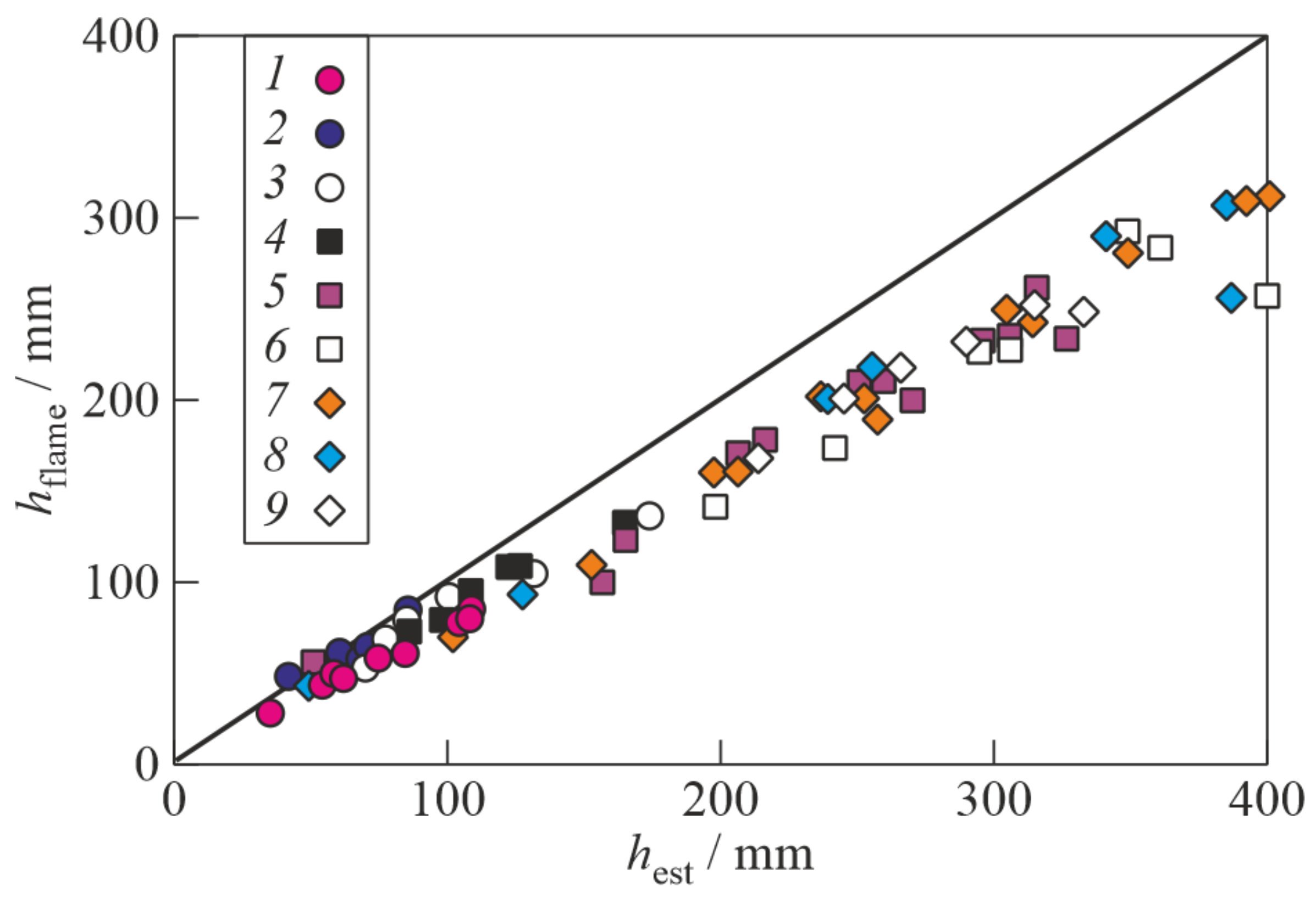
Figure 2 shows the h flame vs. h est dependence, demonstrating the increasing deviation of the true height of the layer, h flame , from its estimated value, h est , with the increase in the combustor fill for combustible mixtures with different dilution of oxidizer with nitrogen N 2 = β / 1 + β . At a mixture layer height of up to 100 mm, the values of h est and h flame differed insignificantly, whereas with an increase in the layer height, the blurring of the layer boundary was becoming noticeable.

3. Results

Table 1 lists the compositions of the nine investigated combustible mixtures C2H4+3(O2 + β N2), the dilution of oxidizer with nitrogen N 2 = β / 1 + β , the Chapman-Jouguet (CJ) detonation parameters (velocity D CJ , temperature T CJ , and pressure P CJ ), and a certain limiting (minimum) height of the mixture layer, h est * , at which DDT was still registered.
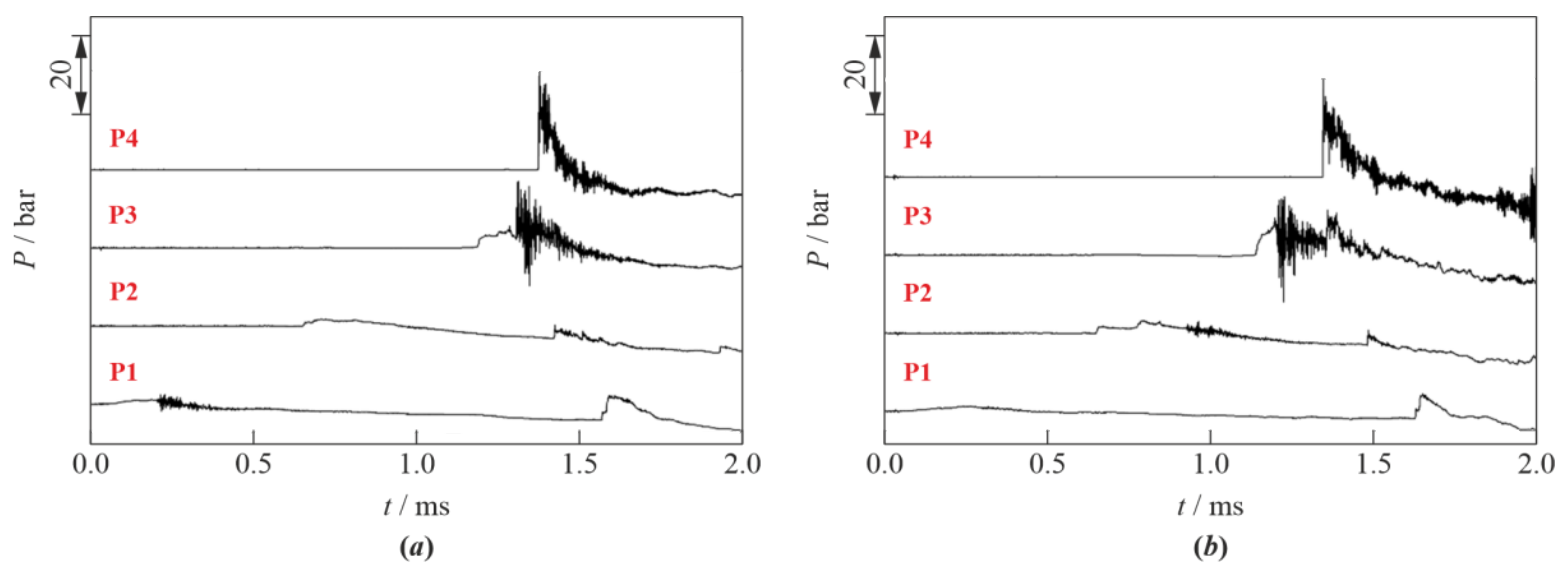
Figure 3 shows the typical pressure records for two experiments in which DDT was observed in a layer with a height close to the limiting (minimum) values of X D D T / t D D T , namely, 556 mm/1.22 ms and 635 mm/1.26 ms, respectively, for test mixtures No. 1 with N 2 = 0 and No. 6 with N 2 = 28.6%vol. in Table 1. The detonation onset was located between the pressure sensors P3 and P4, so the average velocity of the detonation wave could only be determined from the video records.
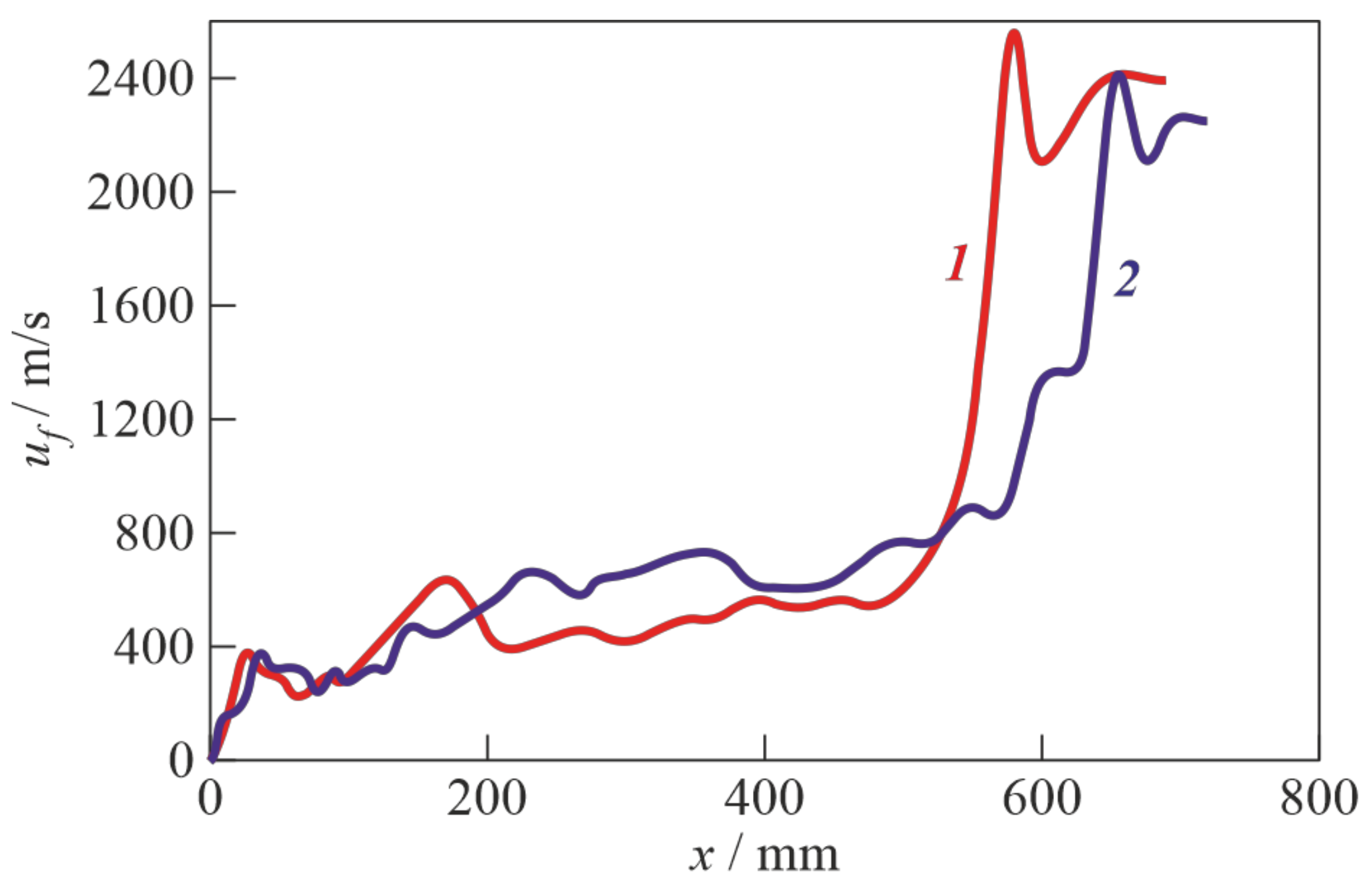
Figure 4 shows the measured dependences of the velocities of the lead luminosity front, u f , on the distance along the slit bottom ( x -axis) at a height of y = 10 mm for the same experiments as in Figure 3. After ignition, the luminosity fronts rapidly accelerated to a speed close to the speed of sound in the initial mixture (~350 m/s). Then, the luminosity fronts were slowly accelerated to 600–800 m/s and, after travelling a distance of 500–600 mm along the slit bottom, the onset of the detonation was observed with a jump-wise increase in the propagation velocities of the luminosity fronts. The measured detonation velocities corresponded to the thermodynamic values, D CJ , for the test mixtures under study: for mixture No. 1, the measured detonation velocity was 2390 ± 160 m/s vs. D CJ = 2376 m/s, and for mixture No. 6, 2250 ± 160 m/s vs. D CJ = 2240 m/s.
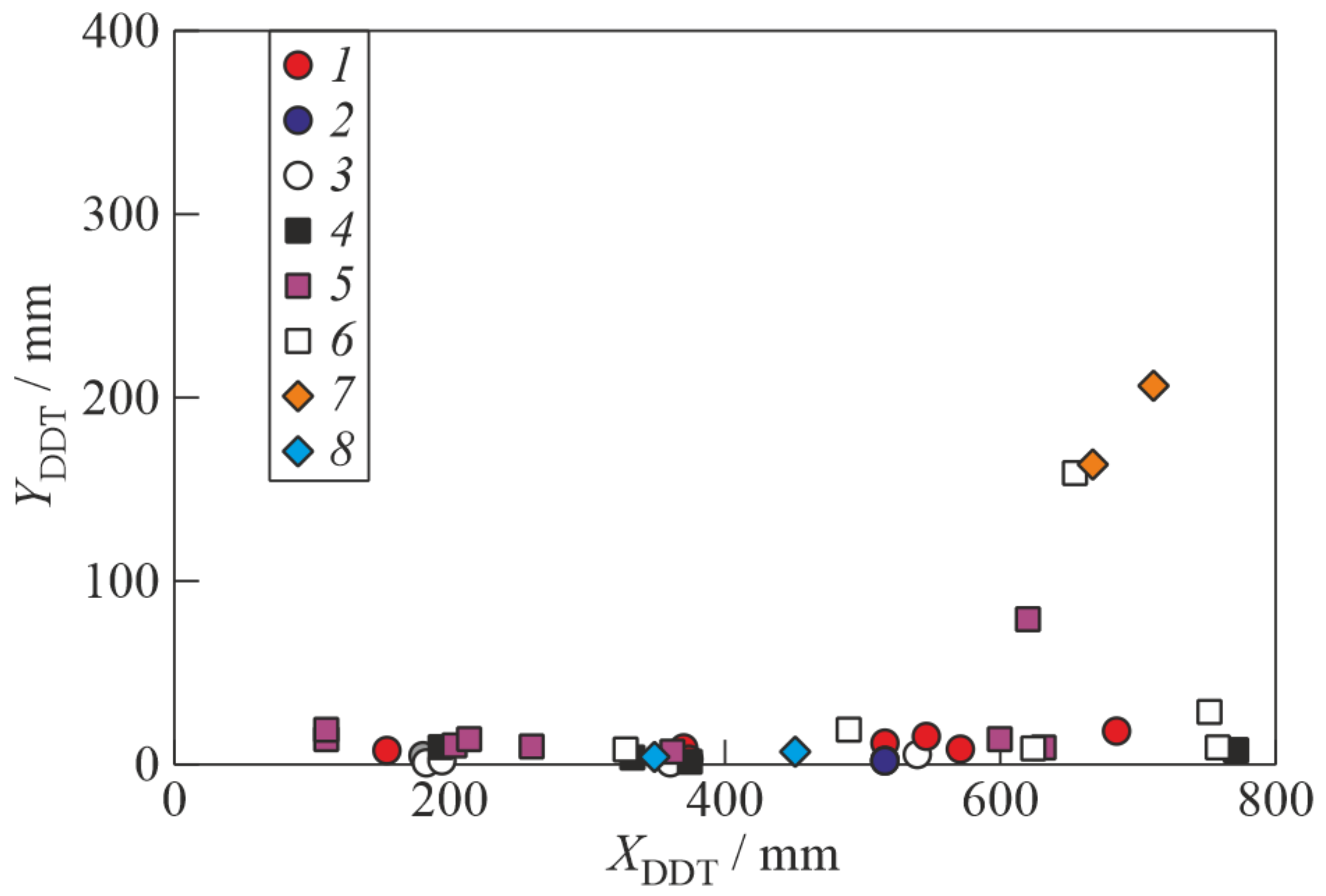
Figure 5 shows a map of the DDT locations in all of the experiments with the onset of detonation, except for the cases when detonation occurred upon the reflection of shock waves from the right end of the slit combustor sealed with thin tissue paper. It can be seen that DDT most often occurred at the bottom of the slit, near the holes for supplying the combustible mixture, i.e., in those places where the turbulence intensity is higher. In rare cases, DDT occurred at a certain distance from the bottom due to a highly developed surface of the flame front and the collision of shock waves reflected from the right end of the slit combustor sealed with thin tissue paper.
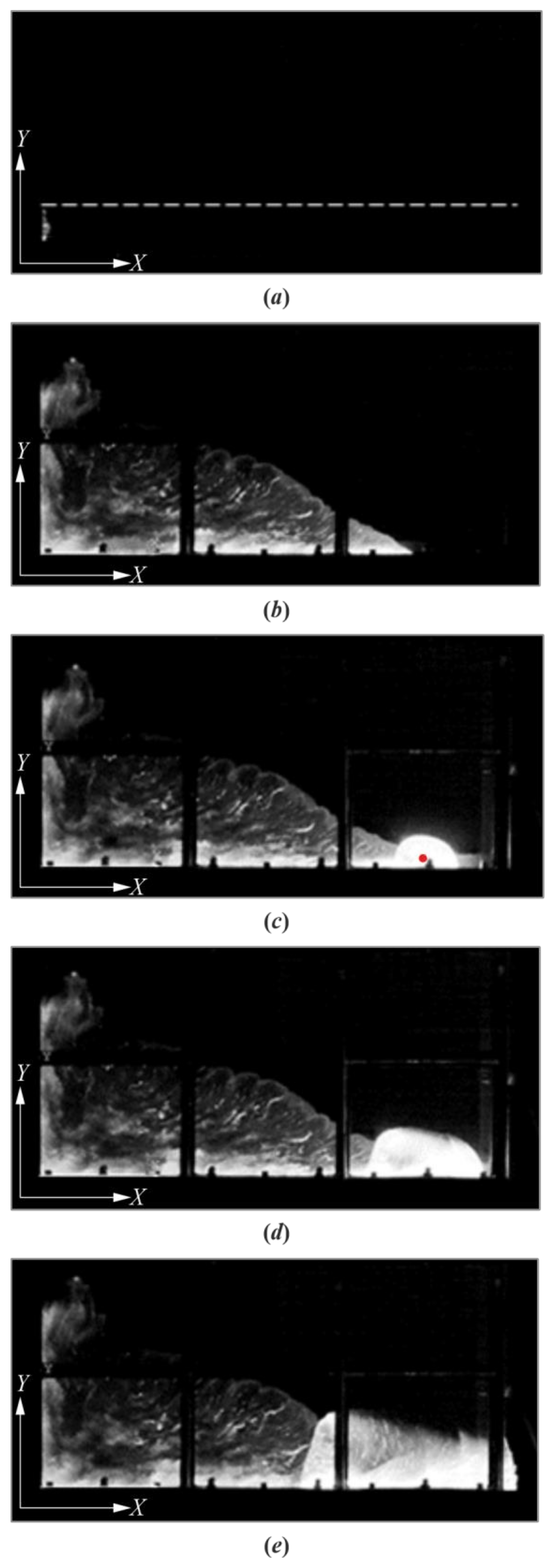
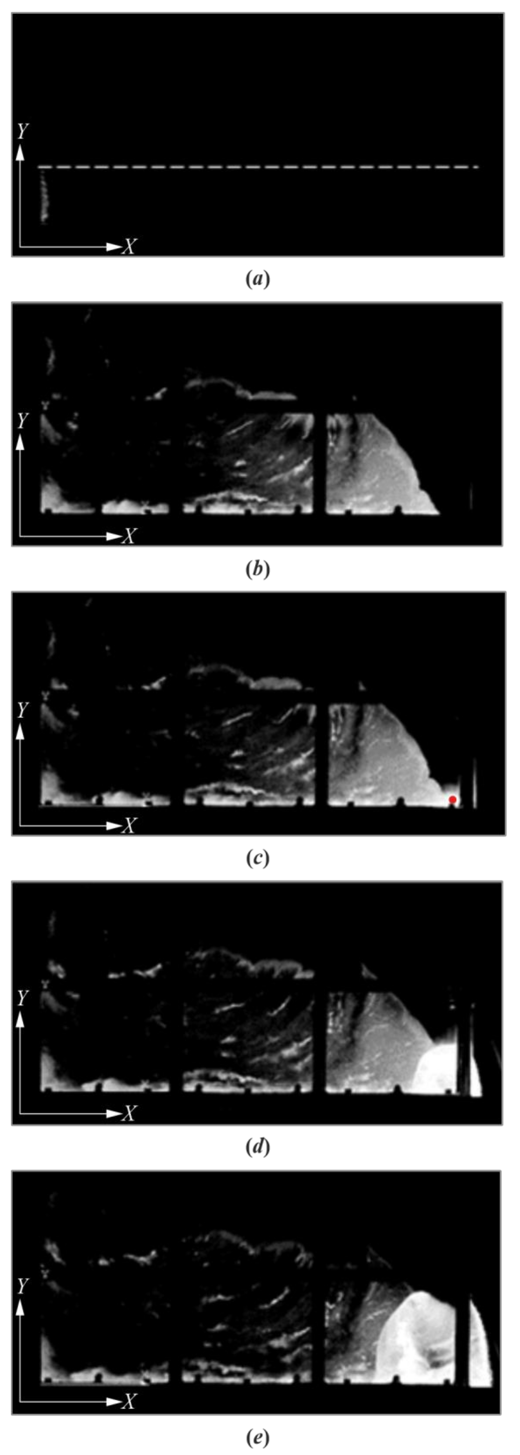
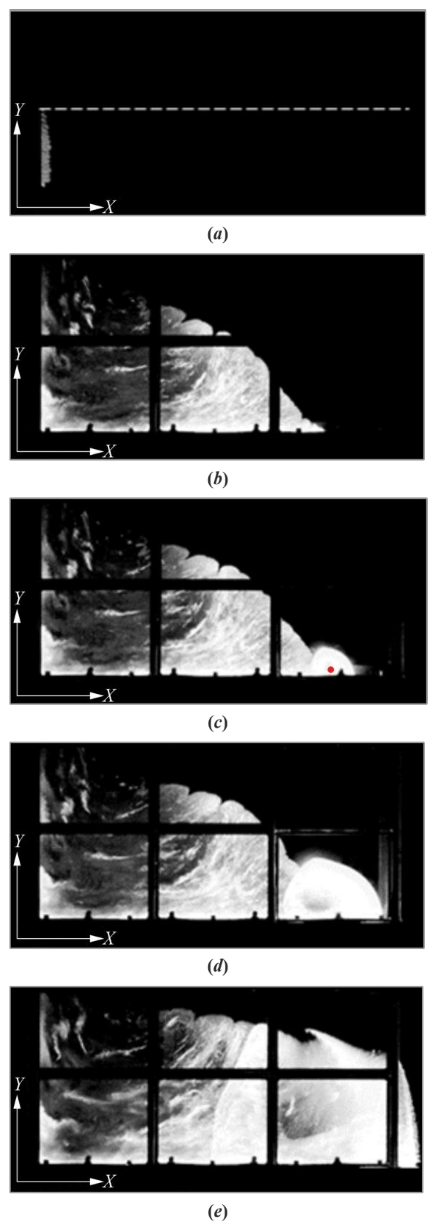
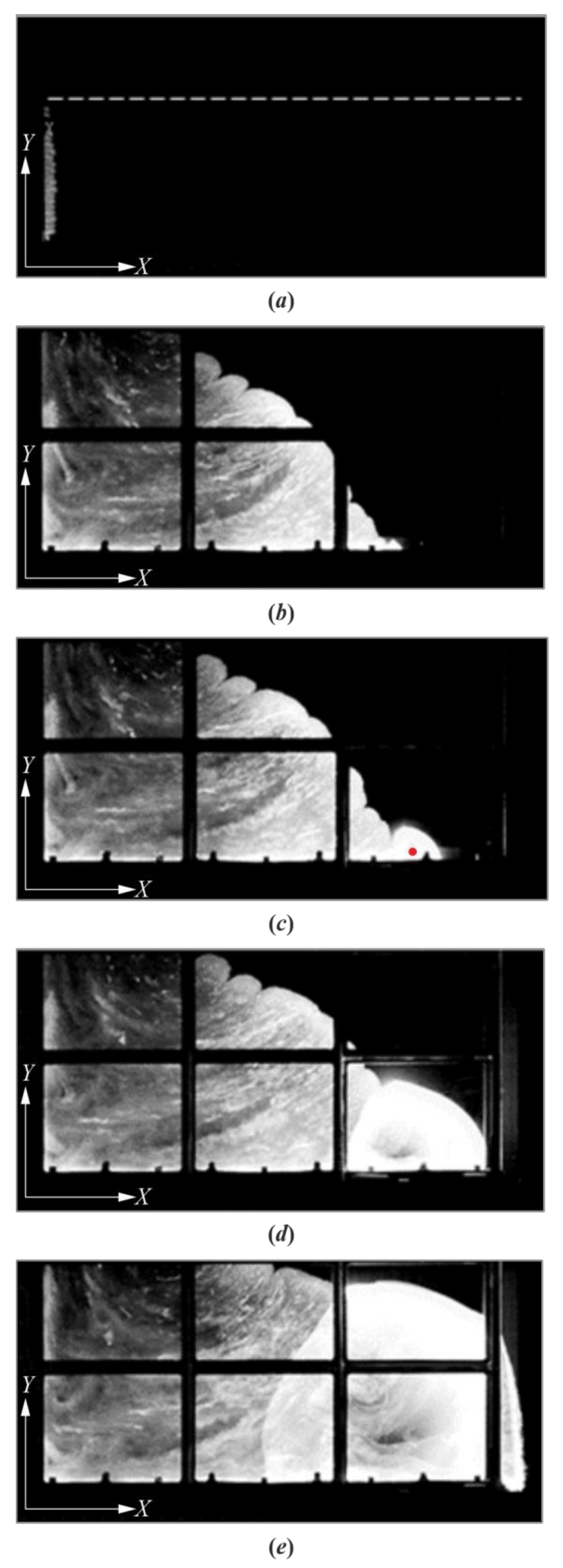
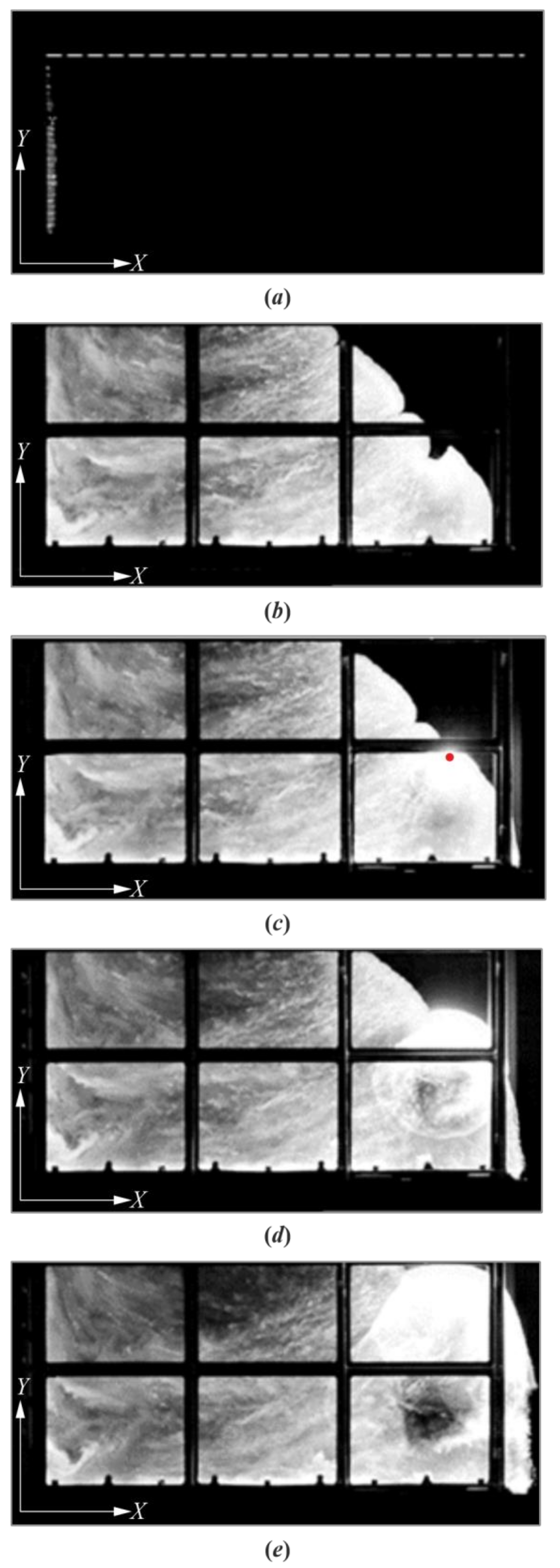
Figure 6, Figure 7, Figure 8, Figure 9 and Figure 10 show the original (unprocessed) frames of the video recording of the detonation onset and the propagation in the layers of the minimum height indicated in Table 1, namely, h est * = 50 mm for mixture No. 1 (see Figure 6); h est * = 110 mm for mixture No. 4 (see Figure 7); h est * = 200 mm for mixture No. 5 (see Figure 8); h est * = 290 mm for mixture No. 6 (see Figure 9), and h est * = 390 mm for mixture No. 7 (see Figure 10). Frames (a) in Figure 6, Figure 7, Figure 8, Figure 9 and Figure 10 provide the images of the flame self-luminosity immediately after mixture ignition. These images were used for determining the values of h flame (horizontal dashed line) in Figure 2 as the visible flame height at the mixture ignition by the multiple spark gaps mounted in the closed left wall of the slit combustor. Frames (b) and (c) in Figure 6, Figure 7, Figure 8, Figure 9 and Figure 10 provide the images of the flame luminosity immediately before and after the onset of detonation, respectively. Finally, frames (d) and (e) in Figure 6, Figure 7, Figure 8, Figure 9 and Figure 10 show the images of the flame luminosity during detonation wave propagation through the mixture layers. Based on the experimental data, such as those presented in Figure 6, Figure 7, Figure 8, Figure 9 and Figure 10, one can conclude that DDT in the layer of the limiting height y h est * is observed at the limiting run-up distances X D D T = 630–800 mm.
With an increase in the layer height above the limiting value, a tendency towards a decrease in the DDT run-up distance was observed. For mixtures Nos. 1–6 (see Table 1), DDT occurred near the slit bottom, i.e., in the layer where the turbulence intensity was higher. It is worth noting that for mixtures Nos. 1–3, the limiting layer height increased gradually with the nitrogen dilution, while the overall flame evolution did not change much. However, for mixtures Nos. 4–6, the limiting layer height increased sharply with nitrogen dilution. For mixture No. 7, DDT apparently occurred after the interaction of the flame with a shock wave reflected from the right end of the slit sealed with thin tissue paper, or due to the self-ignition of a pocket of unreacted mixture formed in the fold of a highly deformed flame.

4. Discussion

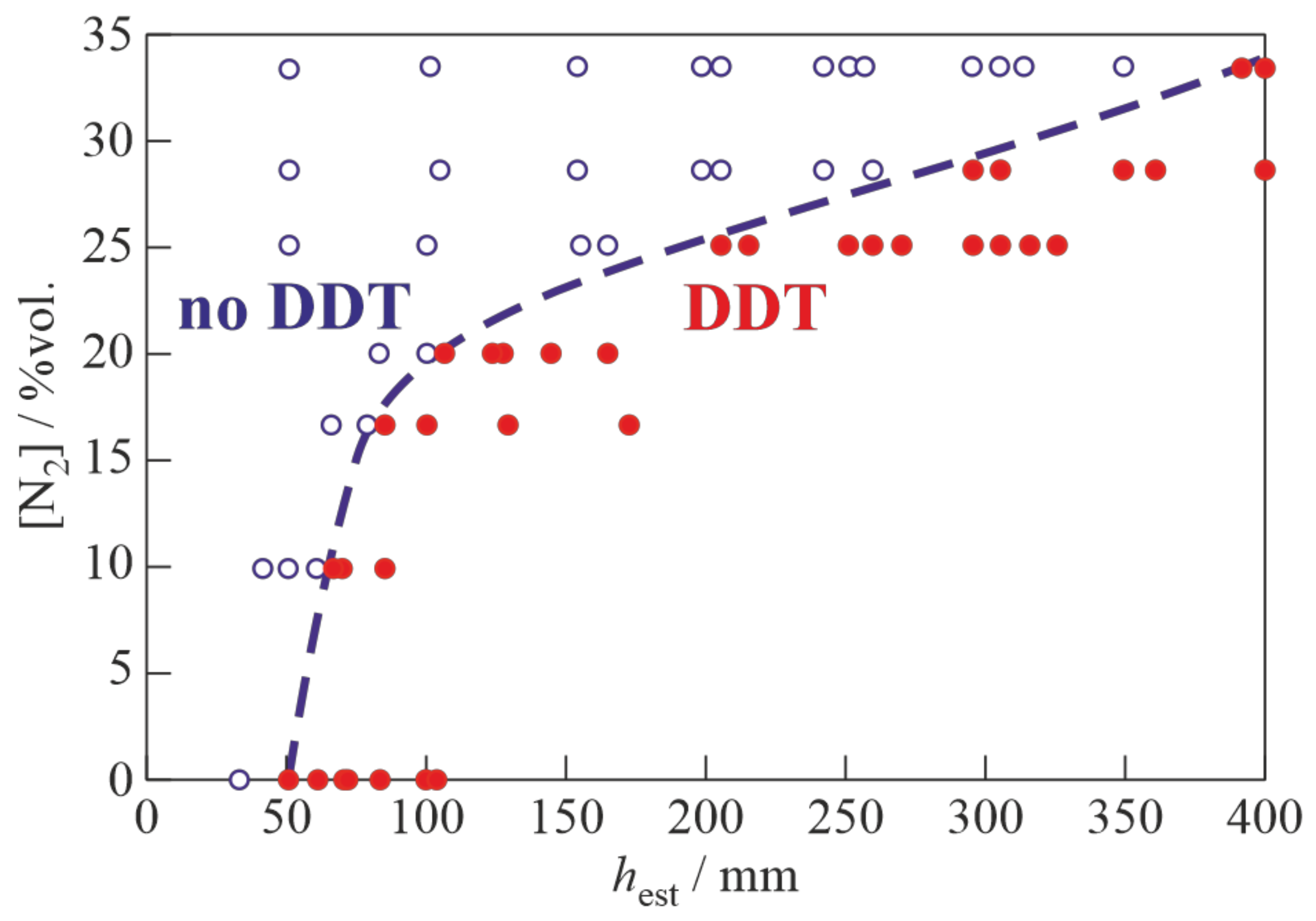
Figure 11 shows a map of the combustion modes for all of the studied mixtures at the N 2 h est plane. The limiting height of the layer, h est * , was searched using the rise-descent method, using the detonation “go–no go” criterion. At first, the height of the mixture layer was increased and then it decreased. Therefore, the limiting value of the layer height was found at least twice: with an increase in the layer height during the first pass and with a decrease in the layer height during the second pass. For the sake of reliability, all of the experiments were repeated several times. As was expected, with an increase in mixture dilution with nitrogen, the limiting height of the detonable layer increased. For mixture No. 9, in Table 1, with N 2 = 40%vol., DDT was observed only in one of six experiments, with the complete fill of the slit with the combustible mixture.
In experiments [16], with the homogeneous stoichiometric mixture C2H4 + 3O2, the height of the detonation wave propagating between the parallel walls of the slit combustor was equal to the height of the layer of the combustible mixture ahead of the detonation wave: approximately 12 mm. In the experiments on DDT considered herein, the limiting layer height for the same mixture was nearly a factor of 4 larger: 50 mm. In our earlier experiments [15], with a separate supply of fuel and oxidizer with the flow rates corresponding to the same overall mixture composition, the limiting layer height was approximately 120 mm, i.e., a factor of 10 larger than in [15], and a factor of 2.4 larger than in the present experiments. This was apparently caused by the finite-rate mixing of fuel and oxidizer, as well as the partial dilution of the mixture with ambient air in experiments [15], where the bottom of the slit combustor was equipped with the injection head containing multiple orifices for the separate supply of fuel and oxidizer. Thus, it appears that for a mild start of the RDE, it is required to fill the combustor to a height at least 4 times higher than the height of the detonation waves continuously rotating in the annular combustor at the steady-state RDE operation.
The curve in Figure 11 approximating the minimum layer height, h est * , required for DDT in the various mixtures diluted with nitrogen, is shown in Figure 12 in relation to the transverse size of the detonation cell, λ . The detonation cell size λ (mm) is calculated as a function of β using the polynomial relationship [17]:
λ = 0.52 + 1.66 β + 0.29 β 2 + 0.49 β 3
This relationship is obtained in [17] based on the data [18,19]. For mixture No. 1 (see Table 1), the calculated size of the detonation cell is 0.52 mm, whereas the measured size is λ   0.38 mm [20]. Similarly, for mixture No. 6, the calculated size of the detonation cell is 1.3 mm, whereas the measured size is λ   0.9 mm [19]. In general, the error in determining the detonation cell size is estimated at ±50%. Compared with the transverse size of the detonation cell, the height of the layers of mixtures No. 1 and No. 6 must exceed ∼(100–130) λ ( λ   0.52 mm [17] and λ   0.38 mm [20]) and (220–320) λ ( λ   1.3 mm [17] and λ   0.9 mm [19]), respectively. The error bars in Figure 12 take into account the errors in determining both h est * and λ .
Even considering the large uncertainties in h est * and λ , there is evidently a sharp change in the nature of the curve for the minimum (limiting) height of the mixture layer required for DDT at N 2 above 20%vol. or β above 0.25. It should also be borne in mind that as the mixture is diluted with more nitrogen, the size of the detonation cell approaches the slit width (5.0 ± 0.4 mm), and the other limiting phenomena associated with heat and momentum losses at the slit walls begin to affect the limiting layer height [21].

5. Conclusions

This work reports the conditions for the mild initiation of a detonation in homogeneous stoichiometric ethylene-oxygen mixtures diluted with nitrogen up to ~40% in a large-scale semi-confined flat-slit combustor, 5.0 ± 0.4 mm wide, simulating an annular RDE combustor. The conditions for the mild detonation initiation were found experimentally using self-luminous high-speed video recording and pressure measurements. It turned out that for the mild initiation of a detonation, it is necessary to ignite the mixture upon reaching the limiting (minimum) height of the layer of the explosive mixture. Thus, for mild detonation initiation in the C2H4 + 3O2 mixture filling such a slit combustor, the height of the mixture layer must exceed the slit width by a factor of approximately 10 (~50 mm), and for the C2H4 + 3(O2 + 2/5 N2) mixture, by a factor of approximately 60. Compared to the transverse size of the detonation cell λ , the minimum height of the layer of such mixtures in the experiments was ~130 λ ( λ   0.38 mm) and ~320 λ ( λ   0.9 mm), respectively. For experiments with more dilute mixtures, it is necessary to increase the slit width. Further research will be aimed at determining the maximum height of the explosive mixture layer for air mixtures of hydrocarbon fuels and the numerical simulation of the accompanying phenomena for the development of similarity (scaling) criteria.

Author Contributions

Conceptualization, S.M.F.; methodology, S.M.F. and I.O.S., investigation, I.O.S., V.S.I., V.S.A. and P.A.G.; data curation, I.O.S.; writing—original draft preparation, S.M.F. and I.O.S.; writing—review and editing, S.M.F.; visualization, I.O.S.; supervision, S.M.F.; project administration, S.M.F.; funding acquisition, S.M.F. All authors have read and agreed to the published version of the manuscript.

Funding

This work was implemented within the framework of the Program of Fundamental Scientific Research of the Russian Federation “Processes of Combustion and Explosion”, reg. No. 122040500073-4, and was funded by the state.

Data Availability Statement

The data is available by request.

Conflicts of Interest

The authors declare no conflict of interest.

References

  1. Anand, V.; Gutmark, E. Rotating detonation combustors and their similarities to rocket instabilities. Progr. Energy Combust. Sci. 2019, 73, 182–234. [Google Scholar] [CrossRef] [Green Version]
  2. Zhou, J.; Song, F.; Xu, S.; Yang, X.; Zheng, Y. Investigation of Rotating Detonation Fueled by Liquid Kerosene. Energies 2022, 15, 4483. [Google Scholar] [CrossRef]
  3. Dubrovskii, A.V.; Ivanov, V.S.; Frolov, S.M. Three-dimensional numerical simulation of the operation process in a continuous detonation combustor with separate feeding of hydrogen and air. Russ. J. Phys. Chem. B 2015, 9, 104–119. [Google Scholar] [CrossRef]
  4. Voitsekhovskii, B.V. Stationary detonation. Dokl. Akad. Nauk SSSR 1959, 129, 1254–1256. [Google Scholar]
  5. Sommers, W.P.; Morrison, R.B. Simulation of condensed-explosive detonation phenomena with gases. Phys. Fluids 1962, 5, 241–248. [Google Scholar] [CrossRef] [Green Version]
  6. Dabora, E.K.; Nicholls, J.A.; Morrison, R.B. The influence of a compressible boundary on the propagation of gaseous detonations. Proc. Symp. (Intern.) Combust. 1965, 10, 817–830. [Google Scholar] [CrossRef]
  7. Adams, T.G. Do weak detonation waves exist? AIAA J. 1978, 16, 1035–1040. [Google Scholar] [CrossRef]
  8. Ivanov, M.F.; Fortov, V.E.; Borisov, A.A. Numerical simulation of the development of a detonation in gas volumes of finite thickness. Combust. Explo. Shock Waves 1981, 17, 332–338. [Google Scholar] [CrossRef]
  9. Rudy, W.; Kuznetsov, M.; Porowski, R.; Teodorczyk, A.; Grune, J.; Sempert, K. Critical conditions of hydrogen–air detonation in partially confined geometry. Proc. Combust. Inst. 2013, 34, 1965–1972. [Google Scholar] [CrossRef]
  10. Kuznetsov, M.; Yanez, J.; Grune, J.; Friedrich, A.; Jordan, T. Hydrogen combustion in a flat semiconfined layer with respect to the Fukushima Daiichi accident. Nucl. Eng. Des. 2015, 286, 36–48. [Google Scholar] [CrossRef]
  11. Li, J.; Mi, X.; Higgins, A.J. Geometric scaling for a detonation wave governed by a pressure-dependent reaction rate and yielding confinement. Phys. Fluids 2015, 27, 027102. [Google Scholar] [CrossRef]
  12. Reynaud, M.; Virot, F.; Chinnayya, A. A computational study of the interaction of gaseous detonations with a compressible layer. Phys. Fluids 2017, 29, 056101. [Google Scholar] [CrossRef]
  13. Bykovskii, F.A.; Zhdan, S.A.; Vedernikov, E.F. Continuous spin detonations. J. Propul. Power 2006, 22, 1204–1216. [Google Scholar] [CrossRef]
  14. Grune, J.; Sempert, K.; Haberstroh, H.; Kuznetsov, M.; Jordan, T. Experimental investigation of hydrogen–air deflagrations and detonations in semiconfined flat layers. J. Loss Prevent. Proc. Ind. 2013, 26, 317–323. [Google Scholar] [CrossRef]
  15. Shamshin, I.O.; Ivanov, V.S.; Aksenov, V.S.; Gusev, P.A.; Frolov, S.M. Experimental study of the initial stage of the operation process in detonation rocket and air-breathing engines. In Advances in Detonation Research; Frolov, S.M., Ed.; Torus Press: Moscow, Russia, 2022; pp. 17–20. [Google Scholar] [CrossRef]
  16. Taguchi, T.; Yamaguchi, M.; Matsuoka, K.; Kawasaki, A.; Watanabe, H.; Itouyama, N.; Kasahara, J.; Matsuo, A. Investigation of reflective shuttling detonation cycle by schlieren and chemiluminescence photography. Combust. Flame 2022, 236, 111826. [Google Scholar] [CrossRef]
  17. Wu, M.-H.; Kuo, W.-C. Transmission of near-limit detonation wave through a planar sudden expansion in a narrow channel. Combust. Flame 2012, 159, 3414–3422. [Google Scholar] [CrossRef]
  18. Matsui, H.; Lee, J.H. On the measure of the relative detonation hazards of gaseous fuel–oxygen and air mixtures. Proc. Symp. (Intern.) Combust. 1979, 17, 1269–1280. [Google Scholar] [CrossRef]
  19. Moen, I.O.; Donato, M.; Knystautas, R.; Lee, J.H. The influence of confinement on the propagation of detonations near the detonability limits. Proc. Symp. (Intern.) Combust. 1981, 18, 1615–1622. [Google Scholar] [CrossRef]
  20. Kawasaki, A.; Kasahara, J. A novel characteristic length of detonation relevant to supercritical diffraction. Shock Waves 2020, 30, 1–12. [Google Scholar] [CrossRef]
  21. Gelfand, B.E.; Frolov, S.M.; Nettleton, M.A. Gaseous detonations-a selective review. Prog. Energy Combust. Sci. 1991, 17, 327–371. [Google Scholar] [CrossRef]
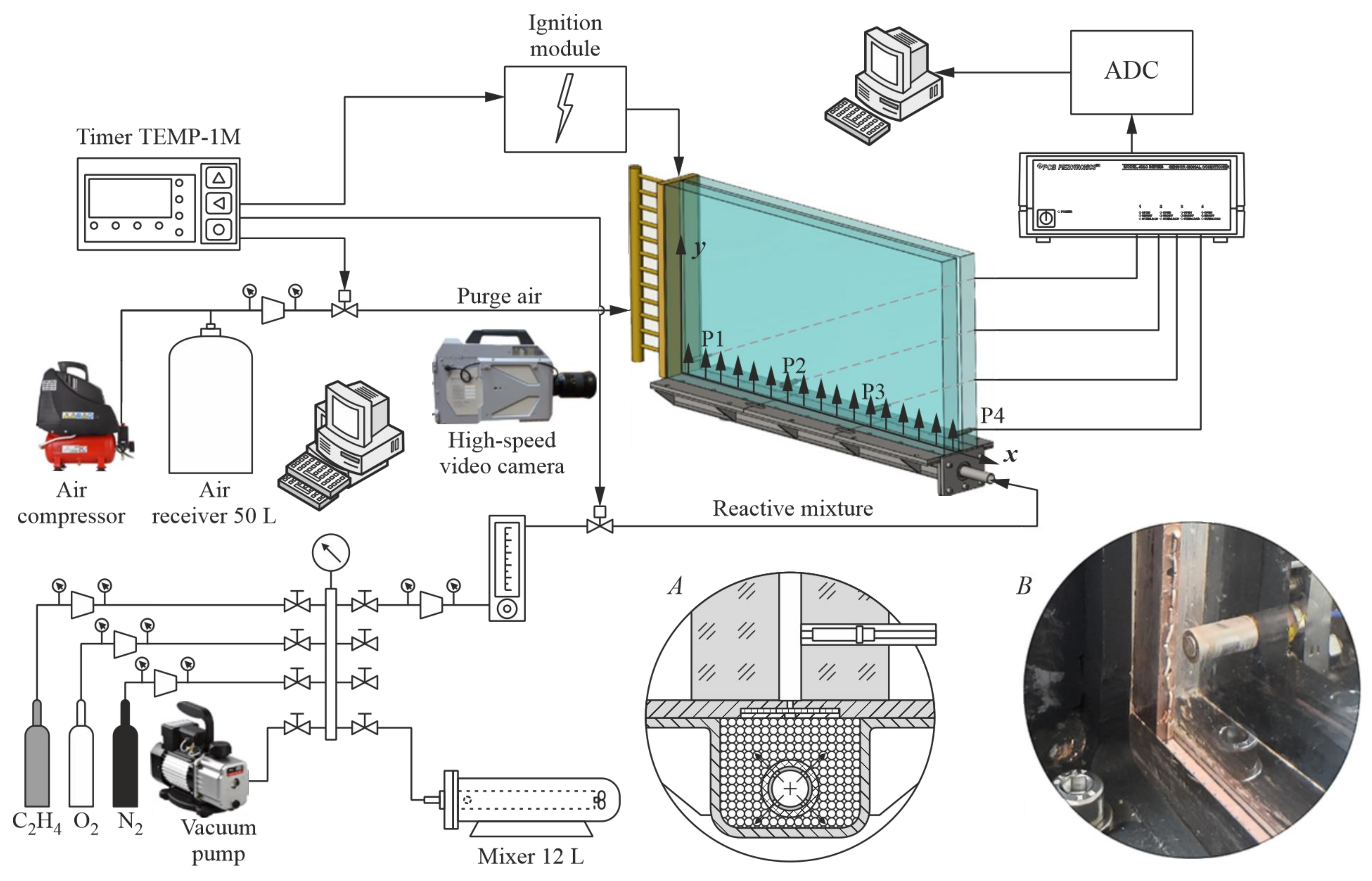
Figure 1. Schematic of experimental setup with a slit combustor. Insert A shows the details of mixture supply to the slit combustor. Insert B shows the view of the closed left end of the slit combustor.
Energies 16 01098 g001
Figure 2. The difference between the true height of the combustible mixture layer ( h flame ) and its estimated value ( h est ). The line corresponds to the equality of these values: 1— N 2 = 0%vol.; 2—10%vol.; 3—17%vol.; 4—20%vol.; 5—25%vol.; 6—29%vol.; 7—33%vol.; 8—38%vol.; and 9—40%vol.
Energies 16 01098 g002
Figure 3. Typical measured pressure histories indicating the onset of detonation in (a) the 70-mm layer of the C2H4 + 3O2 mixture and in (b) the 250-mm layer of the C2H4 + 3(O2 + 2/5 N2) mixture.
Energies 16 01098 g003
Figure 4. Luminosity front velocities, u f , vs. the distance, x , along the bottom of the slit combustor at y = 10 mm: the onset of detonation (1) in the 70-mm layer of the C2H4 + 3O2 mixture and (2) in the 250-mm layer of the C2H4 + 3(O2 + 2/5 N2) mixture.
Energies 16 01098 g004
Figure 5. The map of DDT locations in the slit combustor: 1— N 2 = 0%vol.; 2—10%vol.; 3—16.7%vol.; 4—20%vol.; 5—25%vol.; 6—28.6%vol.; 7—33.3%vol.; and 8—37.5%vol.
Energies 16 01098 g005
Figure 6. The onset of detonation in the layer of minimum height 50 mm; mixture C2H4 + 3O2; X D D T = 640 mm, Y D D T = 7 mm, t D D T = 1.81 ms: (a) t = 0.12 ms; (b) 1.80 ms; (c) 1.83 ms; (d) 1.85 ms; and (e) 1.90 ms. Red dot indicates the position of DDT.
Energies 16 01098 g006
Figure 7. The onset of detonation in the layer of minimum height 110 mm; mixture C2H4 + 3(O2 + ¼ N2), X D D T = 750 mm, Y D D T = 12 mm, t D D T = 1.52 ms: (a) t = 0.18 ms; (b) 1.50 ms; (c) 1.52 ms; (d) 1.55 ms; and (e) 1.59 ms. Red dot indicates the position of DDT.
Energies 16 01098 g007
Figure 8. The onset of detonation in the layer of minimum height 200 mm; mixture C2H4 + 3(O2 + 1/3 N2), X D D T = 630 mm, Y D D T = 8 mm, t D D T = 1.21 ms: (a) t = 0.14 ms; (b) 1.20 ms; (c) 1.23 ms; (d) 1.26 ms; and (e) 1.35 ms. Red dot indicates the position of DDT.
Energies 16 01098 g008
Figure 9. The onset of detonation in the layer of minimum height 290 mm; mixture C2H4 + 3(O2 + 2/5 N2), X D D T = 635 mm, Y D D T = 5 mm, t D D T = 1.27 ms: (a) t = 0.20 ms; (b) 1.25 ms; (c) 1.28 ms; (d) 1.32 ms; and (e) 1.40 ms. Red dot indicates the position of DDT.
Energies 16 01098 g009
Figure 10. The onset of detonation in the layer of minimum height 390 mm; mixture C2H4 + 3(O2 + ½ N2), X D D T = 665 mm, Y D D T = 162 mm, t D D T = 1.56 ms: (a) t = 0.20 ms; (b) 1.55 ms; (c) 1.57 ms; (d) 1.60 ms; and (e) 1.64 ms. Red dot indicates the position of DDT.
Energies 16 01098 g010
Figure 11. The domains of DDT and no DDT in terms of the height of the layer and nitrogen dilution: empty symbols—no DDT; filled symbols—DDT. The dashed curve shows the conditional boundary of the DDT—no DDT domain in the C2H4 + 3(O2 + βN2) mixture.
Energies 16 01098 g011
Figure 12. The minimum height of the layer normalized by the transverse size of the detonation cell λ as a function of nitrogen content in the C2H4 + 3(O2 + βN2) mixture. The lines show the approximation of experimental data. Error bars include the uncertainties in both h est * and λ .
Energies 16 01098 g012
Table 1. Compositions of the studied combustible mixtures, their Chapman–Jouguet detonation parameters, and the minimum layer height required for DDT.
No.Mixture β N 2 ,
%vol.
D CJ ,
m/s
T CJ ,
K
P CJ ,
bar
h est * ,
mm
1C2H4+3O2002376393833.950
2 C 2 H 4 + 3   ( O 2 + 1 9 N2)0.1110.02331387932.465
3 C 2 H 4 + 3   ( O 2 + 1 5 N2)0.2016.72299384031.480
4 C 2 H 4 + 3   ( O 2 + 1 4 N2)0.2520.02283381930.9110
5 C 2 H 4 + 3 ( O 2 + 1 3 N2)0.3325.02259378530.2200
6 C 2 H 4 + 3   ( O 2 + 2 5 N2)0.4028.62240376029.6290
7 C 2 H 4 + 3   ( O 2 + 1 2 N2)0.5033.32215372228.8390
8 C 2 H 4 + 3   ( O 2 + 3 5 N2)0.6037.52191368728.1>400
9 C 2 H 4 + 3   ( O 2 + 2 3 N2)0.6740.02177366427.6>400
Disclaimer/Publisher’s Note: The statements, opinions and data contained in all publications are solely those of the individual author(s) and contributor(s) and not of MDPI and/or the editor(s). MDPI and/or the editor(s) disclaim responsibility for any injury to people or property resulting from any ideas, methods, instructions or products referred to in the content.