1. Introduction
With the intensification of energy consumption worldwide, the development of unconventional energy sources such as deep sea and deep land has gradually become one of the research focuses. In these deep unconventional oil and gas development processes, drilling engineering has the characteristics of large investment and high risk, and its cost accounts for about half of the oil exploitation process. With the increasing drilling depth, the difficulty of drilling gradually rises due to complex geological conditions, the traditional mechanical drilling methods show the characteristics of high energy consumption, low efficiency, long period, and high cost, especially in the deep volcanic rock drilling process. Through the field data analysis, it is found that during the deep volcanic rock [
1,
2,
3,
4], drilling process, the mechanical drilling speed shows a significant downward trend with the increase of the abrasive property of strata. For example, the formation compaction degree is high, the rock drillability is low, the abrasiveness is high, the average drillability extreme value is more than 8 grade, and the mechanical drilling speed in deep formation is only 1/4~1/10 of that in upper and middle stratainXushen block of Songliao Basin.
To solve the issues mentioned above, a number of new rock-breaking methods have emerged in recent years, such as high-pressure water jet rock breaking, thermal energy rock breaking, ultrasonic rock breaking, laser drilling rock breaking, and high-voltage electric pulse rock breaking [
5]. Among them, high-voltage pulse rock-breaking technology (EPD, electrical pulse drilling) is a new technology developed in the past decades. It employs a plasma channel, water jet, or shock wave produced by high-voltage pulse discharge to destroy rock [
5,
6]. Compared with other rock-breaking methods, it has the advantages like environmental protection, directional rock breaking, and easy control over rock breaking process, and thus is called a “green” rock-crushing technology to deal with complex hard rock [
7,
8]. With the rapid development of modern technology and the integration across scientific subjects, the application of this technology in the industry is gradually drawing attention [
9,
10].
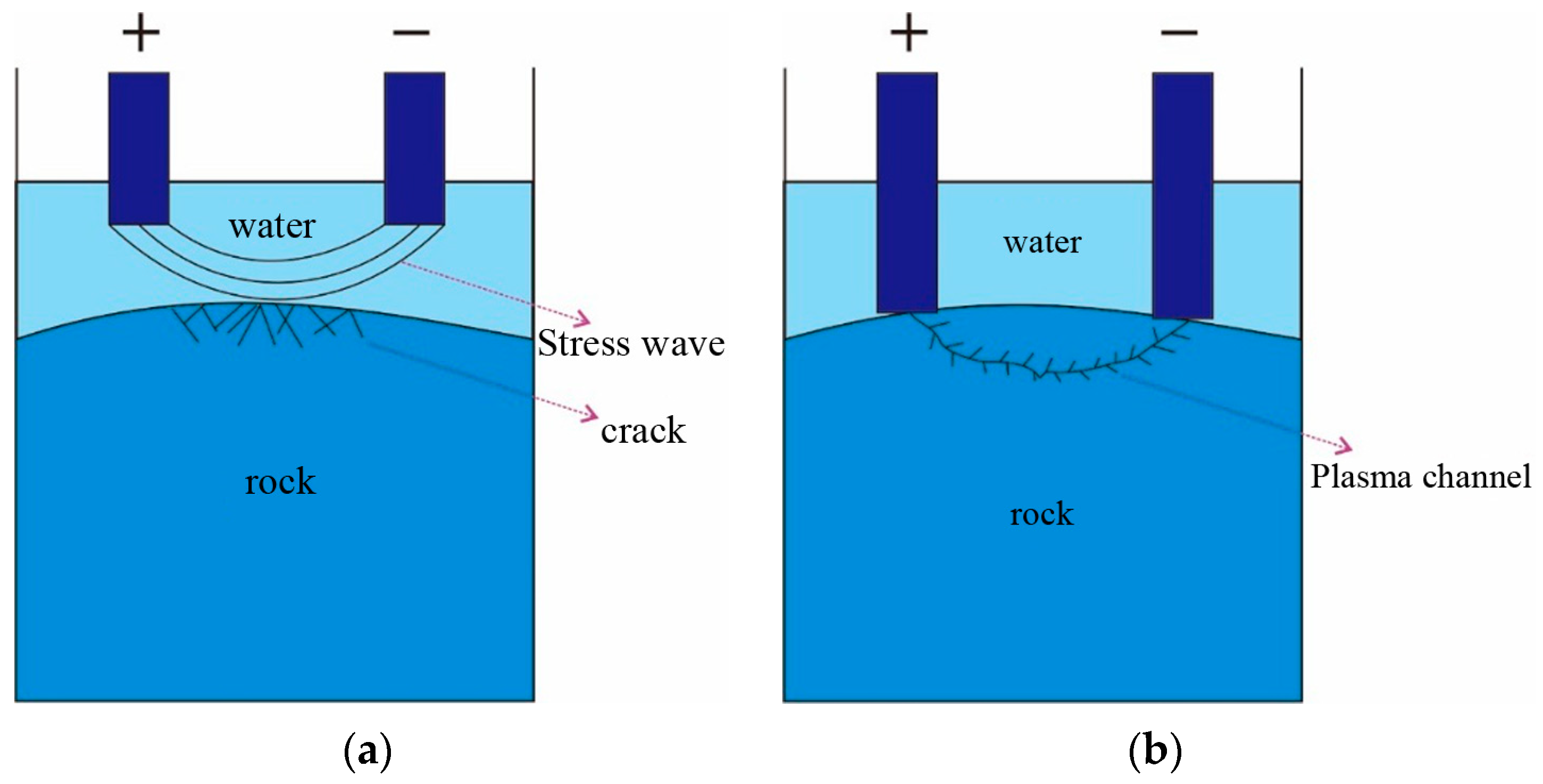
High voltage electric pulse rock breaking can be divided into electro-hydraulic rock breaking and electric pulse rock breaking according to different discharge positions (
Figure 1). Electro-hydraulic rock breaking means that the liquid material is broken down by high voltage electricity, the discharge plasma channel is generated in the liquid material, and the shock wave and pressure wave generated from the discharge channel will break the rock. Electric pulse rock breaking means that the discharge plasma channel is generated inside the rock, and the stress generated by the expansion of the plasma channel will break the rock. Combined with the existing downhole drilling environment, drilling equipment, and drilling technology, the high voltage electric pulse drilling system uses high voltage electric pulse rock breaking technology. High voltage electric pulse rock breaking, according to the electrode discharge form can be divided into two kinds: (1) electrode and rock is not in contact, through the high voltage discharge will be liquid breakdown water jet or shock wave broken rock; (2) The electrode is in contact with the rock, and the rock is broken by surface discharge. The difference between the electrode and the rock is that the plasma channel is generated in different positions.
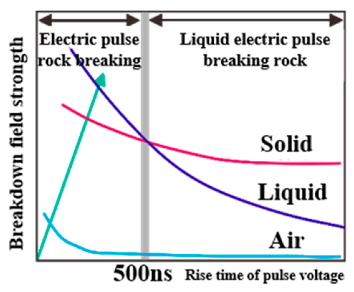
In the late 1950s, Tomsk Polytechnic University [
11] found that when the discharge time is less than 500 ns, the electric breakdown field strength of liquid is higher than that of rock. The relationship between the breakdown voltage and time of gas, solid, and liquid is shown in
Figure 2. When the pulse voltage release time is less than 500 ns [
12], the electric breakdown field strength of the different states is air < solid < liquid, and, at this time, when the electric pulse is used to break the rock, the rock is broken before the liquid, the plasma channel is formed inside the rock, and the rock is broken.
Given the complexity of the rock itself and electric breakdown theory, it is difficult to study the mechanism of high voltage pulse breaking through rock. S. Boev [
13] and other researchers divided the whole crushing process into two stages by analyzing the discharge, polarization and electric field redistribution caused by the pulse in liquid and solid near the electrode: (1) forming a discharge channel in a rock medium, (2) the discharge channel diffuses sharply outward and breaks the rock due to the explosive introduction of electric pulse energy. Andres [
14] and his colleagues found that the breakdown through a composite solid by a single pulse is totally different from that by electric shock of a uniform dielectric insulation material caused by discharge. Through calculation, they concluded that rock affected by High Voltage Pulse splits along the interface between mineral components with different permittivity/conductivity. V. V. Burkin [
15] and his team analyzed the theory of electric pulse breaking rock from the power characteristics of electric breakdown, and proposed physical and mathematical models (
Figure 3).
As for the damage process of high voltage electric pulse rock breaking (Abbreviated as HVEPRB later in the paper), Andres et al. [
16,
17] believe that rock breakage is caused by the expansion of plasma channels inside rocks, which leads to the radial explosion impact of rocks, and the resulting shock wave causes rock breakage. Lisitsyn et al. [
18] concluded through experiments that there are many gas cavities of different sizes inside the rock. Under the action of a high voltage pulse, the cavity breaks, and the current flows into the gas cavity, were resulting in a large amount of plasma heat and shock wave generation, and finally the rock cracks and cracks. Bluhm et al. [
19] pointed out that the cause of rock breakage is the result of the combined action of the pulse wave and tensile stress. Burkin et al. [
20] pointed out that at lower power, rock breakage mainly relies on tensile stress, while at higher power, rock breakage is caused by the direct influence of compressive stress.
Based on the theoretical research, the scholars have carried out relevant experimental research on the problem that the HVEPRB technology is difficult to calculate theoretically. Wielen et al. [
21] used a high-voltage pulse generator to carry out high-voltage rock-breaking experiments on 20 kinds of rocks and determined the effects of pulse voltage, discharge times, electrode spacing, and discharge rate on rock crushing caused by pulse discharge. Toyohisa Fujita et al. [
11] conducted relevant experimental studies on the influence of the wavefront duration of a single pulse on the rock-breaking process of an electric pulse. I.v.tomoshki et al. [
22] and Cho et al. [
23,
24] developed the plasma channel micro-hole drilling technology to solve the cost problem of exploration and underground data acquisition and completed relevant surface experiments. The experimental results are shown in
Figure 4. K. Kusaiynov et al. [
25] developed a small electrical pulse device for crushing natural stone, as shown in
Figure 5. B. M. Kovalchuk et al. [
26] designed a portable high-voltage pulse generator for rock-crushing experiments.
2. Theoretical Background of Rock Breaking Process by HVEP
According to the classical theory, the energy injected into the plasma channel through the external energy storage capacitor, ignoring the influence of the radiation generated when the plasma channel expands, mainly acts on two aspects, namely, increasing the internal energy of the plasma channel and the work done by the plasma channel to the rocks around the channel.
where
Qi represents the energy in the plasma channel,
Qh represents the pressure potential energy, and
Qv represents the kinetic energy of the plasma.
The plasma channel acts on the rock in the form of a shock wave. The shock wave generated by the external work done by the plasma channel is mainly consumed in the following three parts: firstly, the increase of the internal energy of the rock, secondly, the kinetic energy converted into the rock, and thirdly, the energy dissipated by the shock wave propagating to the insulating liquid.
After energy is injected into the plasma channel, related scholars have many explanations for the damage process of the plasma channel to the rock interior. Among them, Burkin et al. established the rock breakage model under the action of an electric pulse through theories related to the plastic and elastic deformation of rock medium and the dynamics of liquid material. This model proposes that the plasma channel formed under the action of the electrode can be regarded as a cylinder of a constant length and time-varying radius. When the radius of the plasma channel increases with time, the energy inside the plasma channel will have an effect on the rock. When the force reaches a certain strength, the rock will have cracks and be broken. According to the model, under the condition that the energy injected into the plasma channel reaches tens to hundreds of joules, the plasma channel will explode inside the rock, forming the corresponding explosion shock wave, the peak pressure of which is between several hundred MPs and several thousand MPs.
Based on the relevant theories of explosion mechanics and rock mechanics, the influence of plasma channel expansion and explosion on the interior of rock is explored. Under the action of rapidly changing pressure in a very short period, corresponding displacement and deformation are generated at the same time. Such displacement and deformation will transfer among the particles in the interior of the rock, thus forming a disturbance, which is propagated in the form of a shock wave. With the shock wave propagating outward from the plasma channel as the center, the deformation and displacement of different media inside the rock are different due to the influence of the composition and connection mode of various media inside the rock, and the rock is broken. The process of rock breakage caused by plasma channel can be divided into two stages: one is the radial compression stage of the shock wave generated by the expansion and explosion of the plasma channel; Second, under the influence of the overpressure produced by the plasma channel, the radial initial fracture expands rapidly under the action of tensile stress. According to rock failure mechanics theory, under the influence of explosion, rock breakage is mainly tensile failure.
For reference to the classical theory of explosion mechanics, assuming that the rock to be punctured is a liquid, the energy explosion mode of the plasma channel is the initiation of an electric detonation wire inserted into the rock with a negligible radius, and the plasma channel is a cylinder with a radius of 2 mm. The initiation energy acts on the wall of the plasma channel and the maximum pressure
Pm produced by the electric breakdown of the rock can be obtained according to the empirical formula:
where
ρ is the density of the rock, which is assumed to be 3.3 × 10
3 kg/m
3;
ηf denotes the energy efficiency of plasma injection channel, and experience value is 4%;
U0 is voltage;
L is plasma channel radius; and
lch is plasma channel length.
According to the previous hypothesis, the maximum pressure at the moment the rock is shocked is 272 MPa. The shock wave front pressure
P1 can be expressed as
where
l represents the radius of the plasma channel;
δt describes the coefficient of discharge efficiency changing with time, which generally set at 3.6;
t means the moving time of the blast wave in Equation (4);
σ[
T −
t] is the explosion function in Equation (5); expresses the correlation coefficient in Equation (6); and
α0 is the sound velocity in rock, which set 6000 m/s.
where
, the sound velocity in the rock medium, taken as 6000 m/s,
μ indicates the sound coefficient during an electric breakdown, which is set at 0.5; and
K shows the empirical coefficient which is set at 660 MPa·m.
With assumed data, when T ≥ t, concluded P1 = 135.81 MPa. At the interface between the plasma channel and rock, the plasma channel expands and explodes in a very short time, and produces an explosion shock wave. The shock wave acts on the rock interface instantaneously, which makes the state parameters of the rock change suddenly. Therefore, the longitudinal wave velocity of the plasma channel particle is greater than that of the rock particle. In the process of shock wave propagation, there are both projected compression waves and reflected tensile waves. If it is assumed that the explosion instant is a sudden change process, it is mainly reflected in tensile waves. Because the tensile strength of rock is generally one-tenth of the uniaxial tensile strength, in this case, rock breaking is mainly to overcome the ultimate tensile strength of rock, and rock is more likely to be broken.
3. Simulation of HVERB
In order to provide the theoretical basis and basis for the development and application of downhole electric pulse rock breaking equipment, and provide relevant experimental data for the design of downhole electric pulse generator, electrode bit, selection of drilling tools, and process parameters. In this paper, the mechanism and technology of rock breaking by HVEP method are studied, and the functional test is carried out.
According to the existing research, the electric breakdown field strength of rock ranges from 50 kV/cm to 400 kV/cm, while the electric breakdown field strength of solid dielectric materials such as silica film ranges from 200 kV/cm to 10,000 kV/cm, so the electric breakdown of rock has its own special properties. From the microscopic point of view, the rock is composed of a variety of different mineral particles, which are connected by crystallization and cementation. It is impossible to fully fill all the voids in the rock. As shown in
Figure 6 [
27], there are huge pores in the rock, so the bubbles in the rock may play an important role in the electrical breakdown process of the rock. At the same time, from the principle of electric breakdown, we know that the electric breakdown in a solid is closely related to the change of electric field strength (Abbreviated as EFS later in the paper) and the uniformity of EFS inside the rock. For different materials, under the same circumstances, the EFS required for electric breakdown is different. Therefore, it is necessary to analyze the formation stage of the plasma channel in rocks by studying the influence of different factors on the EFS inside rocks.
Through COMSOL Multiphysics finite element analysis software, the influence of bubbles in rock on rock electrical breakdown is simulated and analyzed. By studying the influence of bubbles in rock on the change of EFS inside rocks, the influence of bubbles on rock electrical breakdown is analyzed.
- (1)
The geometric model and mesh generation model are shown in
Figure 7. Since the influence of bubbles is considered in the simulation, the bubbles are magnified to make the bubble boundary contact with the rock boundary in a larger area. Here, the rock is set as a rectangle of 20 mm × 10 mm, and the bubble radius is 3 mm. At the same time, because the quality of the mesh is the key to determining whether the subsequent simulation can converge and whether the convergence result is accurate, and because the model is relatively simple and the number of iterations is less, the model is ultra-refined mesh generation, as shown in
Figure 8. It can be seen from the figure that COMSOL Multiphysics software can refine the boundary mesh of the contact between rock and bubble, which meets the requirements of mesh generation.
- (2)
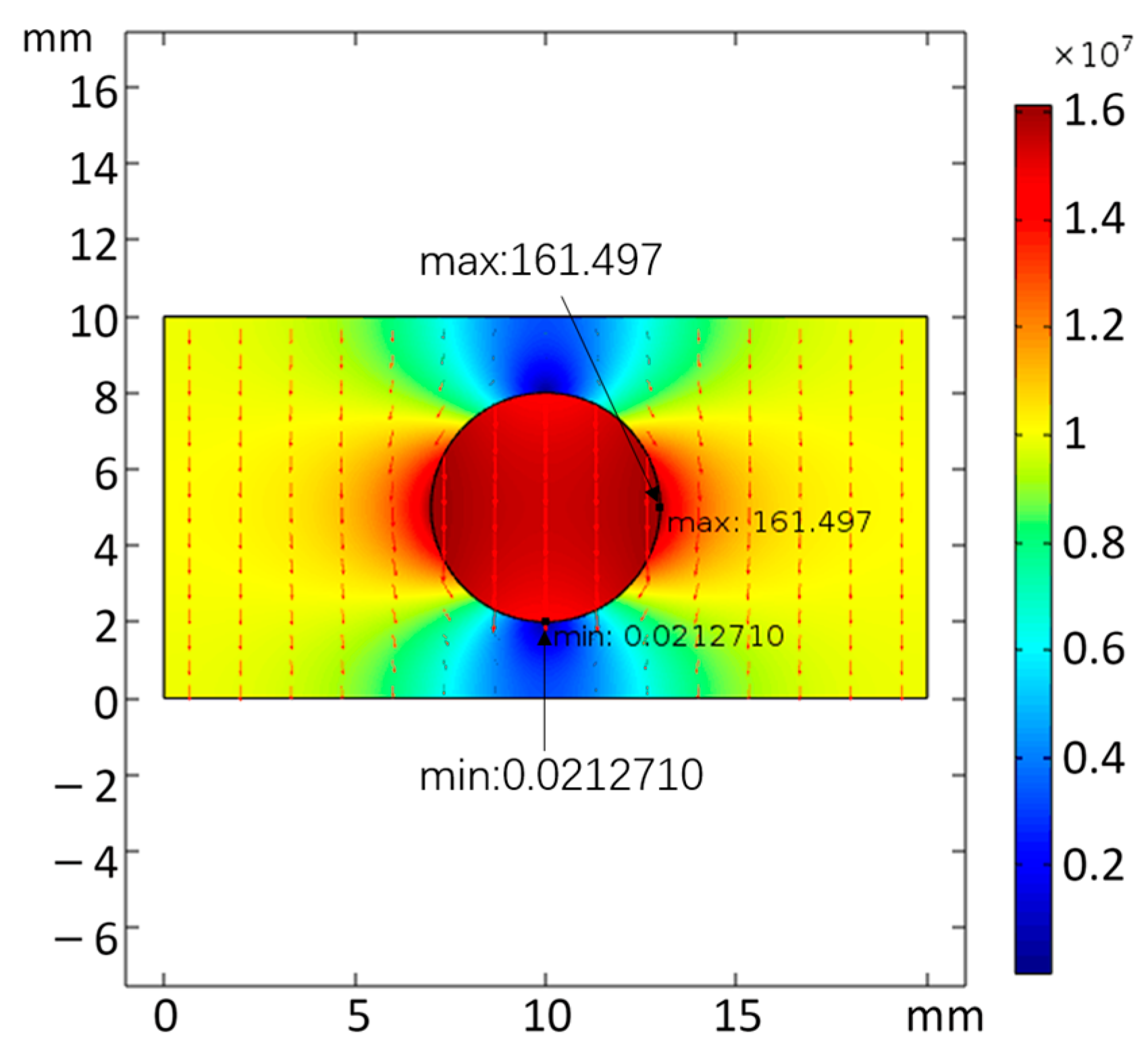
The simulation results of the model are shown in
Figure 9. The EFS is 100 kV/cm which is far from the bubble, while the maximum EFS near the bubble is 161.497 kV/cm. At the same time, the EFS at the upper and lower boundaries of the bubble become lower, and the EFS near the bubble boundary is close to zero. The EFS around the bubble forms a clear difference, and the uniformity of the electric field inside the rock decreases. Under such EFS distribution, the rock breakdown becomes easier.
- (3)
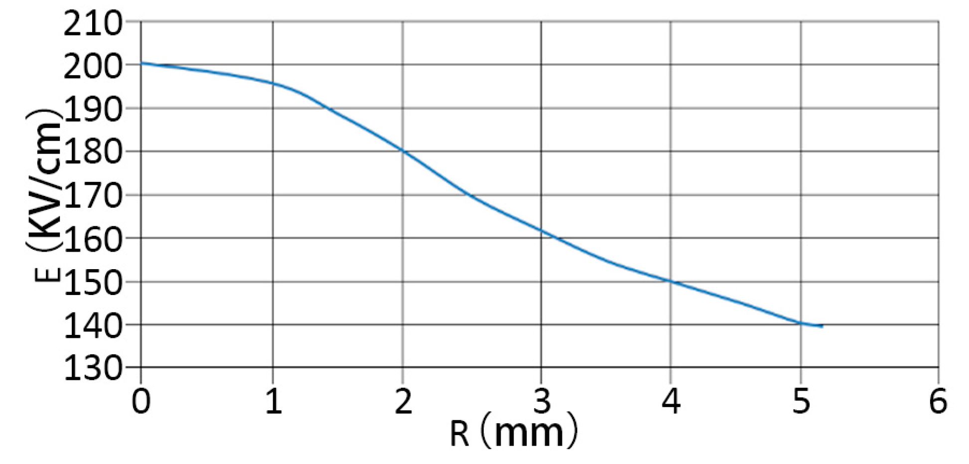
By changing the radius of the middle bubble to adjust the area of the bubble, the influence of the bubble size on the EFS of rock is analyzed, as shown in
Table 1. The fitting curve is shown in
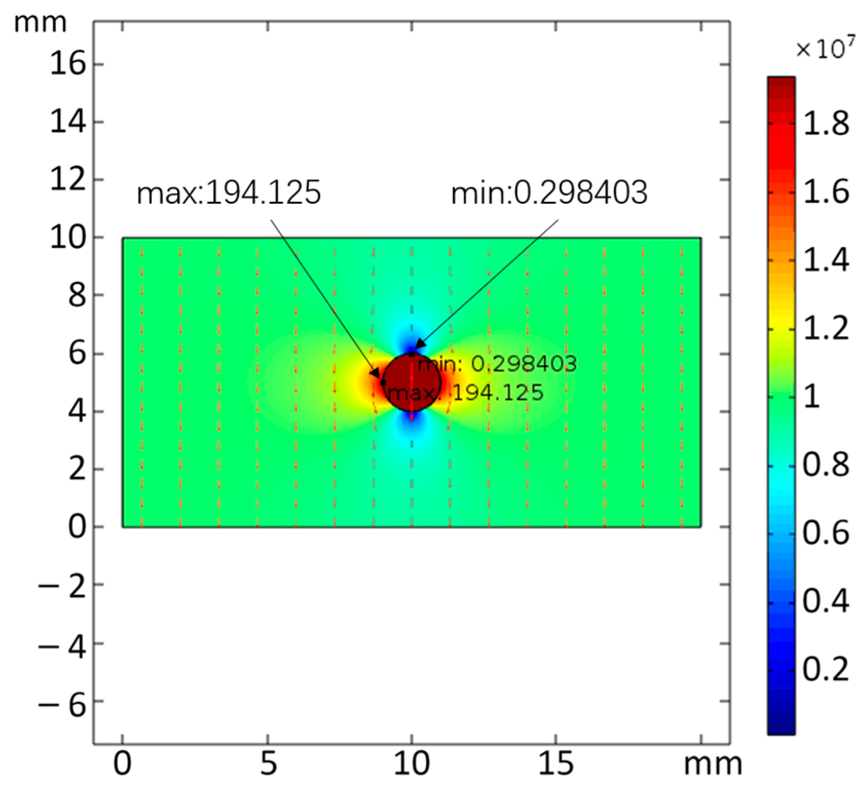
Figure 10. With the decrease in the bubble area, the influence on the EFS inside the rock becomes larger. However, from the comparison between
Figure 9 and
Figure 11, it can be seen that due to the smaller volume of the bubble, the contact between the bubble and the rock boundary becomes smaller, which leads to a smaller range of its influence on the EFS inside the rock. According to the average EFS inside the bubble and inside the rock, with the increase of the bubble volume, the influence range of the bubble on the EFS inside the rock increases, the average EFS inside the rock decreases, and the difference between the maximum and minimum EFS decreases. Therefore, in the interior of rocks, more tiny and disordered bubbles have a greater influence on the uniformity and maximum of EFS than a single big bubble.
- (4)
Using the analytical model of a 2 mm bubble, to explore the effect of distance between the bubble and electric potential on rock EFS. By changing the distance between the bubble center and the high electric potential, the maximum and minimum EFS results of the rock are obtained. As shown in
Table 2, as the distance between the bubble and the electric potential boundary increases, the influence of the bubble on the EFS of the rock increases. However, combined with
Table 2, comparing the influence of the bubble volume on the EFS of the rock, it can be seen that the influence of the distance between the bubble and the electric potential boundary is relatively small.
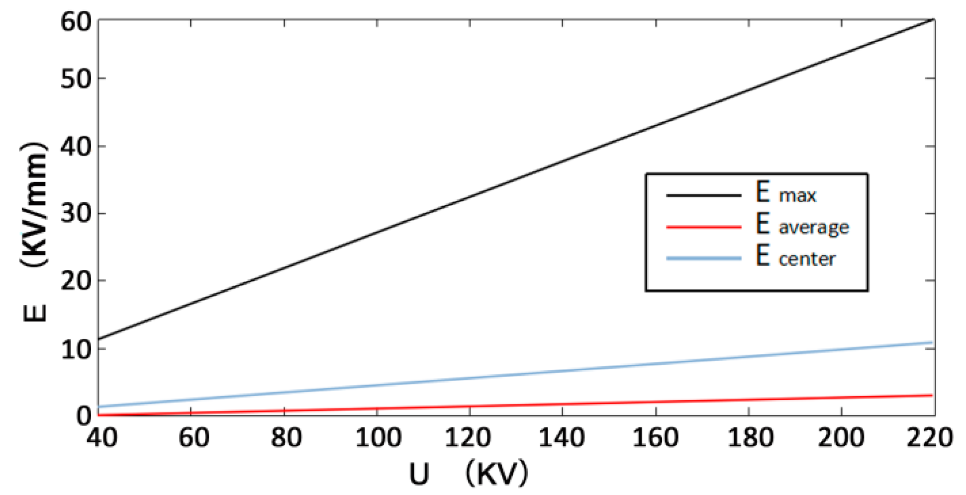
In the process of HVEPRB, the working voltage applied by the electrode has a crucial effect on rock breaking. In order to study the influence of different working voltages on the rock-breaking process of HVEP, the electric field distribution of rock breaking by HVEP under different working voltages is simulated. To set that the electrode spacing is 20 mm, the rock radius is 30 mm, the rock thickness is 10 mm, and the dielectric constant of granite is 7, the electrode radius is 2.5 mm, the dielectric constant of wateris81. The EFS distribution of rock is compared under the condition that the peak working voltage ranges from 40 kV to 220 kV and the step size is 20 kV. The simulation results are shown in
Figure 12.
Figure 13 shows the variation in the maximum electric field intensity, the average EFS, and the central EFS of the rock with time. It can be seen from
Figure 13 that with the increase in working voltage, the maximum EFS inside the rock increases, thus the efficiency of rock breaking by HVEP increases. With the rise of voltage, the energy required for a single pulse of rock breakdown increases, which leads to a decrease in energy utilization. Therefore, in practice, it is recommended that the voltage should be as small as possible within the required voltage range.
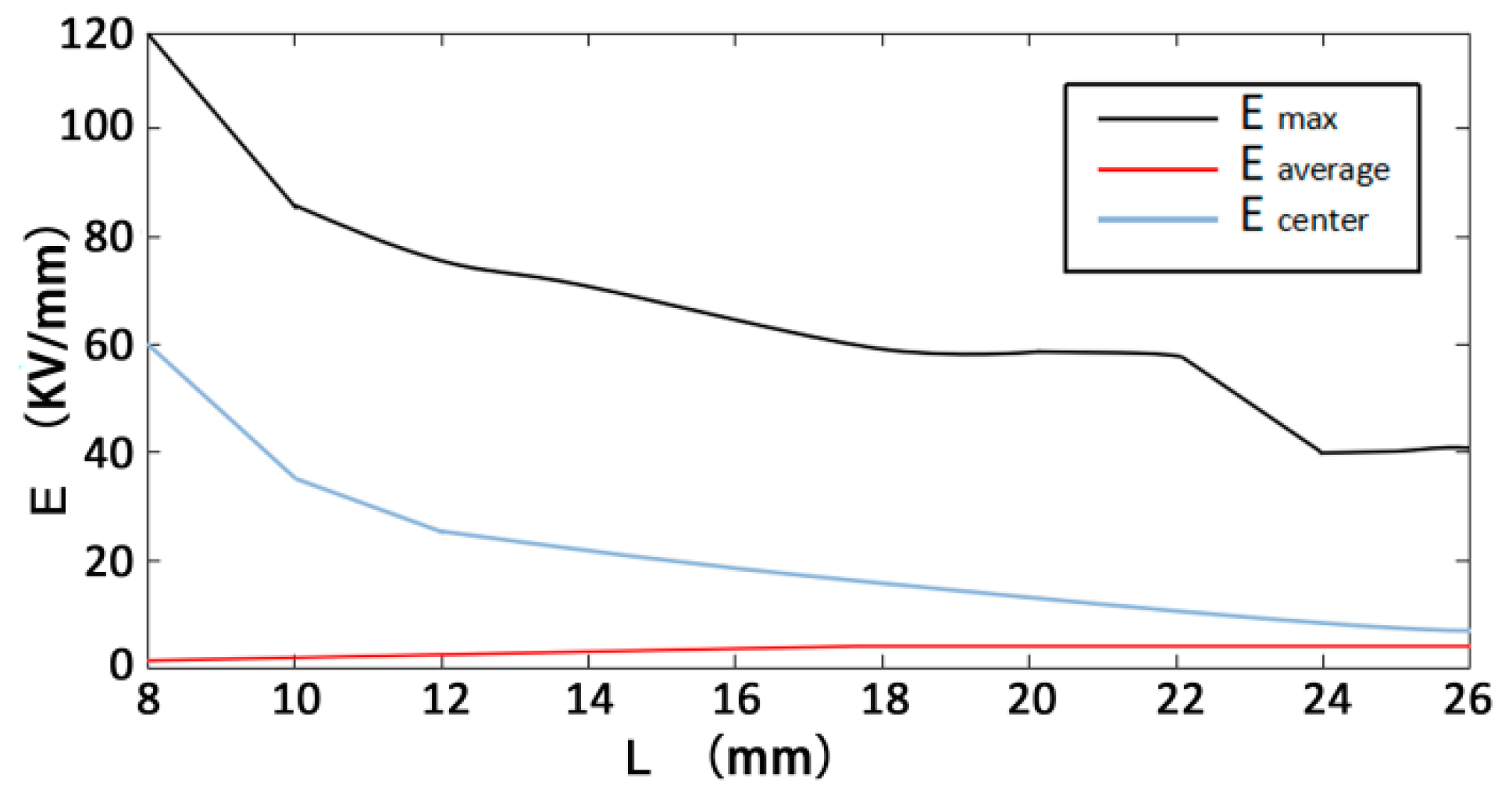
In the simulation of the effect of electrode spacing on the HVEPRB process, the peak voltage is set at 200 kV, the rock radius is 30 mm, the rock thickness is 10 mm, and the dielectric constant of granite is 7, the electrode radius is 2.5 mm, the dielectric constant of water is 81 and remains constant. The electrode spacing is defined as 6 mm to 26 mm, and the step size is 2 mm. According to the change in electrode spacing, the internal electric field intensity curve of granite is shown in
Figure 14. From
Figure 14, it can be seen that in terms of the overall trend, the internal EFS of granite decreases with the increase in electrode spacing. However, within a certain range, smaller electrode spacing is not always better. There is an optimal value of electrode spacing for the rock breaking. At the same time, it can be seen from the curves of the maximum EFS and the central field strength that the maximum EFS and the central field strength change sharply when the electrode spacing is less than 10 mm. The reason is that when the electrode spacing is too small, the shape of the electrode itself and the contact mode with the rock will have an impact on the EFS inside the rock, which cannot be ignored.
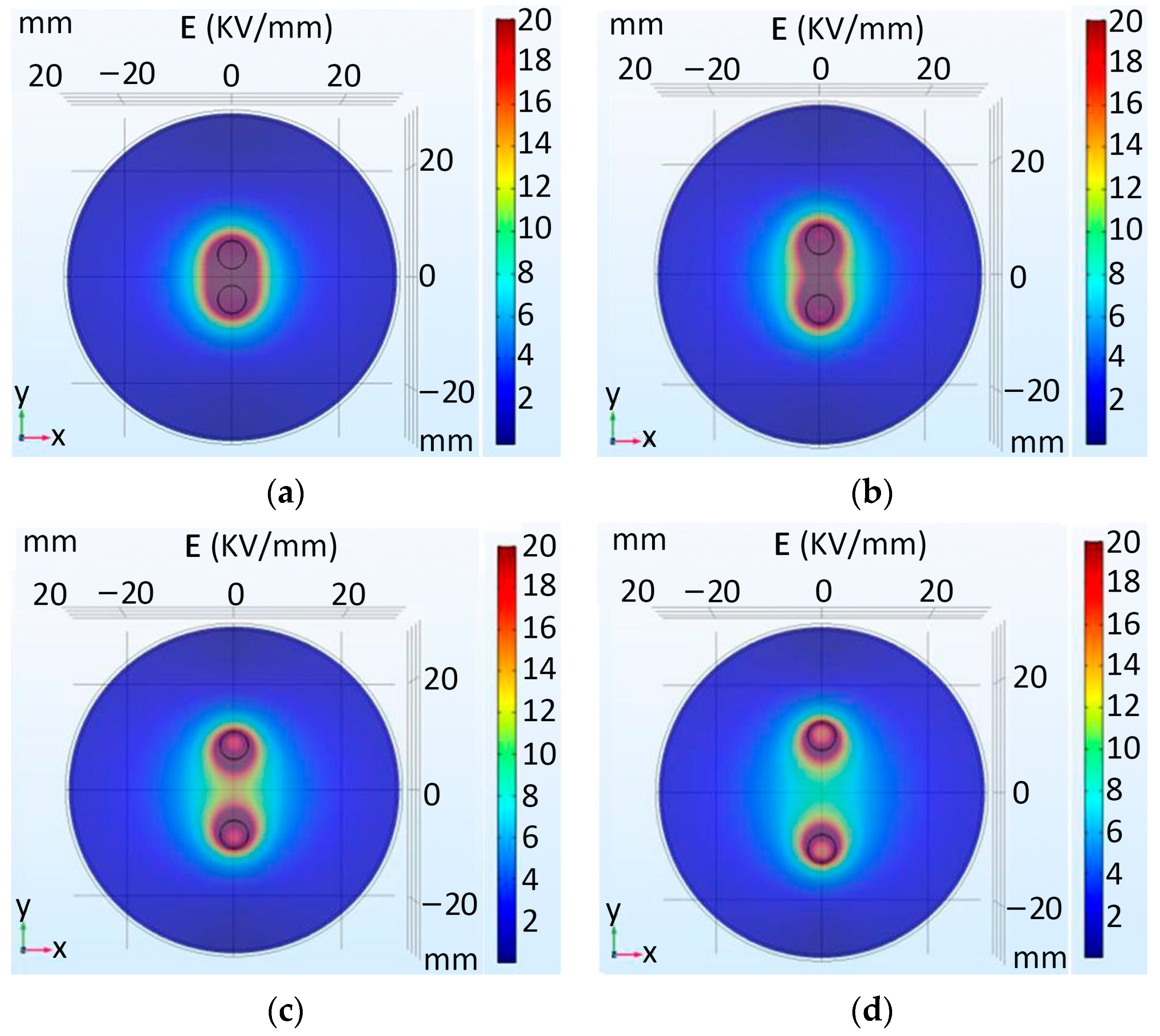
Figure 15 shows the simulation results of the influence of electrode spacing inside granite on the EFS distribution during the HVEPRB. It can be seen from the figure that the maximum EFS inside the granite increases with the decrease in electrode spacing.
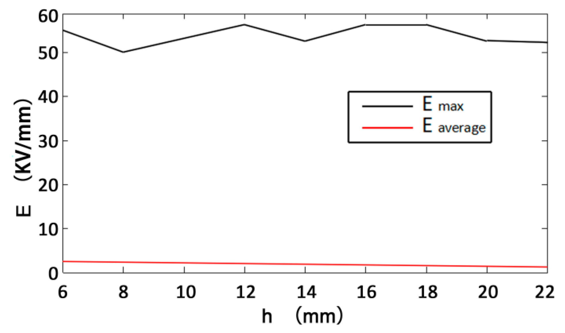
Considering the distribution of electrodes in the drilling process, it is necessary to analyze the influence of rock thickness on the HVEPRB. The peak voltage is set at 200 kV, the radius of the rock is 30 mm, the dielectric constant of granite is 7, the electrode radius is 2.5 mm, the dielectric constant of water is 81, the maximum EFS curve inside the granite is obtained by changing the thickness of the granite, as shown in
Figure 16. It can be seen from the figure that with the increase in the thickness of the granite, the maximum EFS inside the granite generally decreases, but it increases in some areas, and the average EFS of the granite decreases. And it gradually decreases proportionally with the increase of the thickness, because the influence of the voltage can only be applied within a certain thickness. From
Figure 16, it can be shown that the thickness of rock has a certain effect on the HVEPRB, but the influence is limited. When the thickness of rock exceeds the influence range of voltage, the excess thickness of rock has no effect on the HVEPRB.
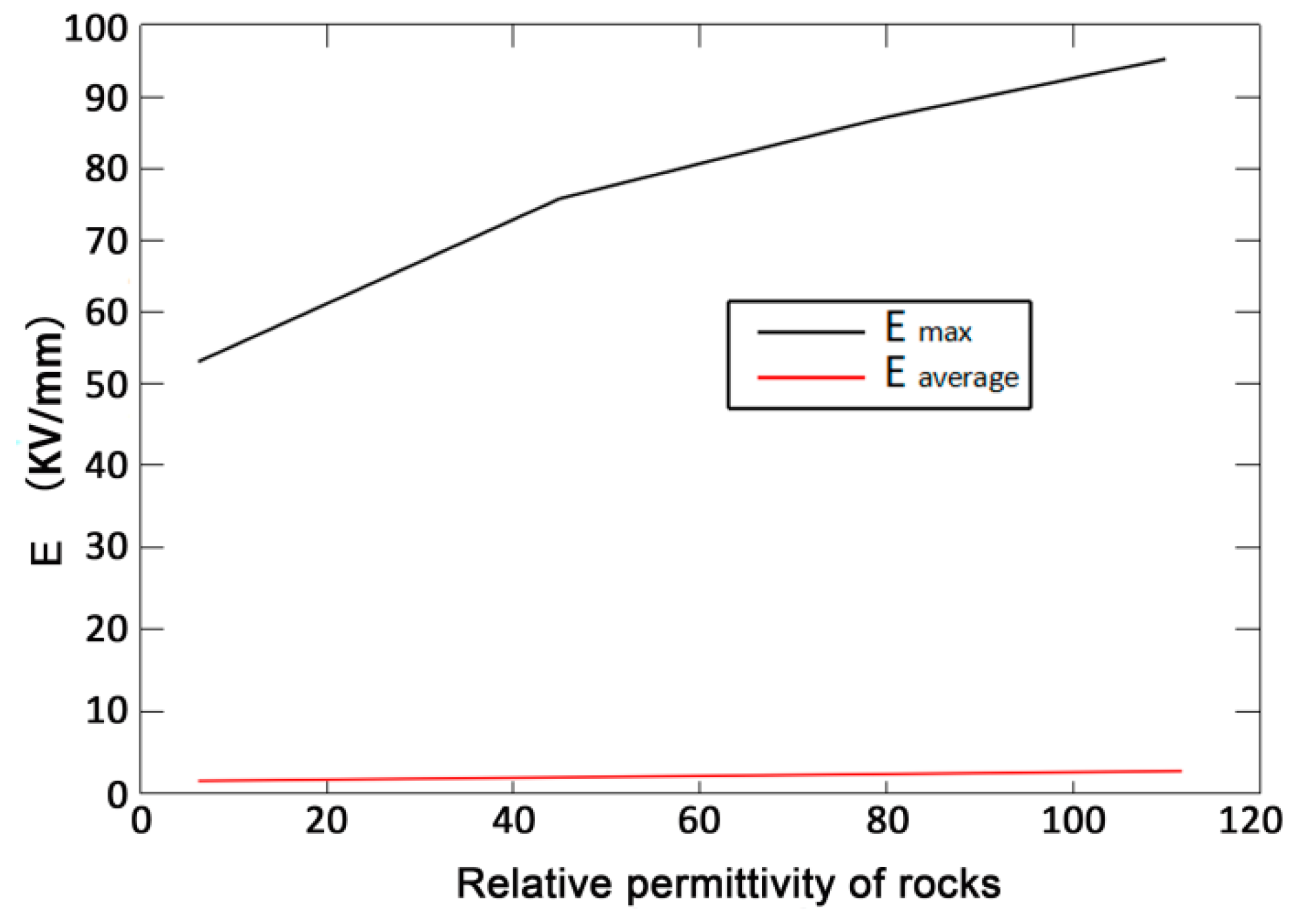
Given the same electrical parameters, different kinds of rocks have different electric breakdown effects due to different relative permittivity. The relative permittivity of several common rocks is shown in
Table 3. The simulation result curve is shown in
Figure 17. It can be seen from the figure that the higher the relative permittivity of rock is, the higher the EFS inside the rock is, and the electric breakdown is more prone to occur. However, with the increase of the relative permittivity of rock, the average EFS inside the rock decreases, and the utilization rate of energy of rock decreases, so the crushing effect of rock decreases.
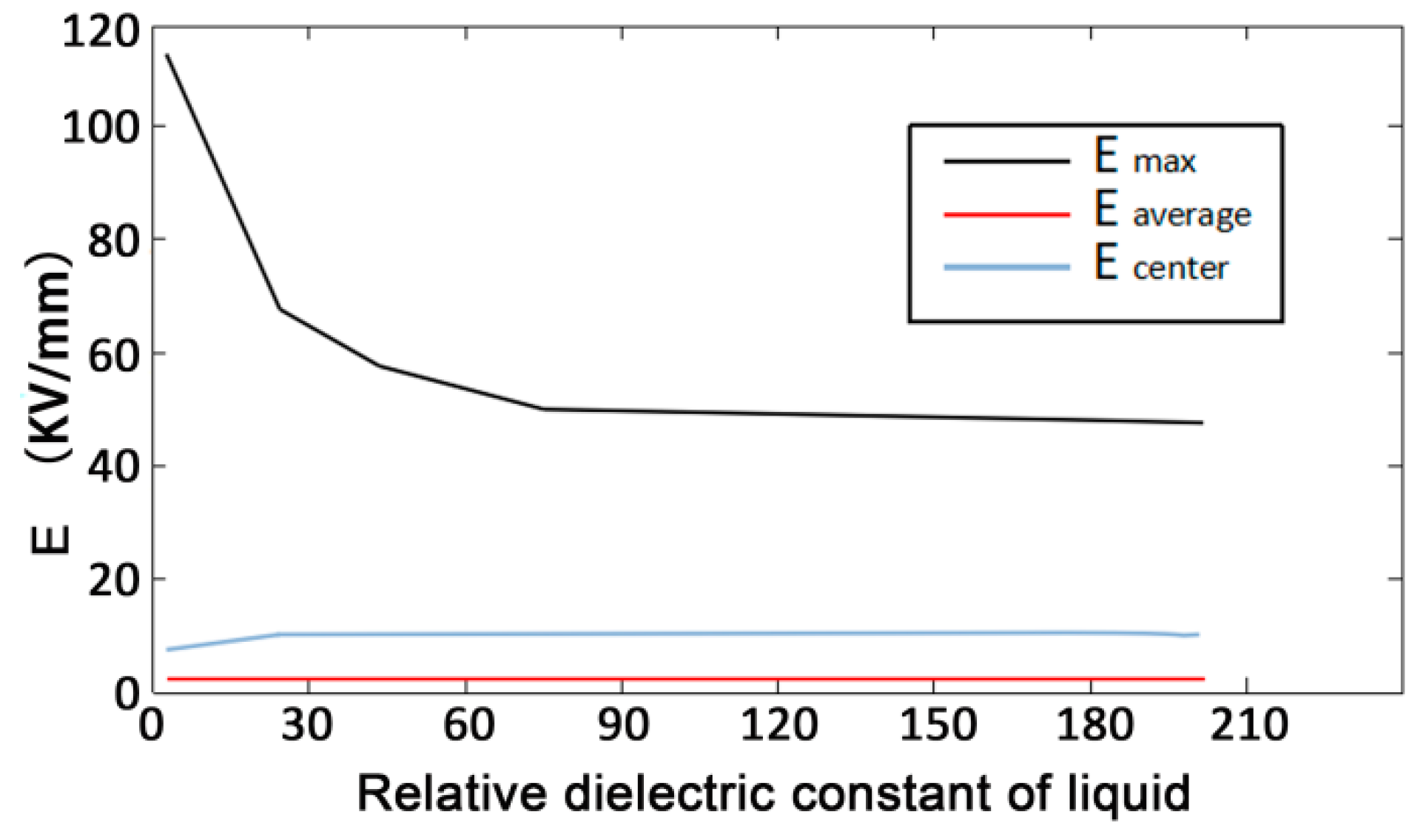
The relative dielectric constant of liquid material will have a certain impact on the HVEPRB.
Table 4 shows the relative dielectric constant of some common liquid materials. In order to obtain the influence of different liquid materials on the HVEPRB, the simulation of rock breaking under different liquid materials in
Table 4 is carried out, respectively. The voltage is set 200 kV, the electrode spacing is 20 mm, the rock radius is 30 mm, the thickness is 10 mm, and the dielectric constant of granite is 7, the electrode radius is 2.5 mm. It can be shown from
Figure 18 that the smaller the dielectric constant of liquid material is, the better the effect on the HVEPRB will be. Transformer oil is the optimal liquid material for the effect of rock breaking, but considering the actual situation and cost, it is generally believed that water is the ideal liquid material.
4. Experimental Study on Rock Breaking of a High-Voltage Electric Pulse Generator
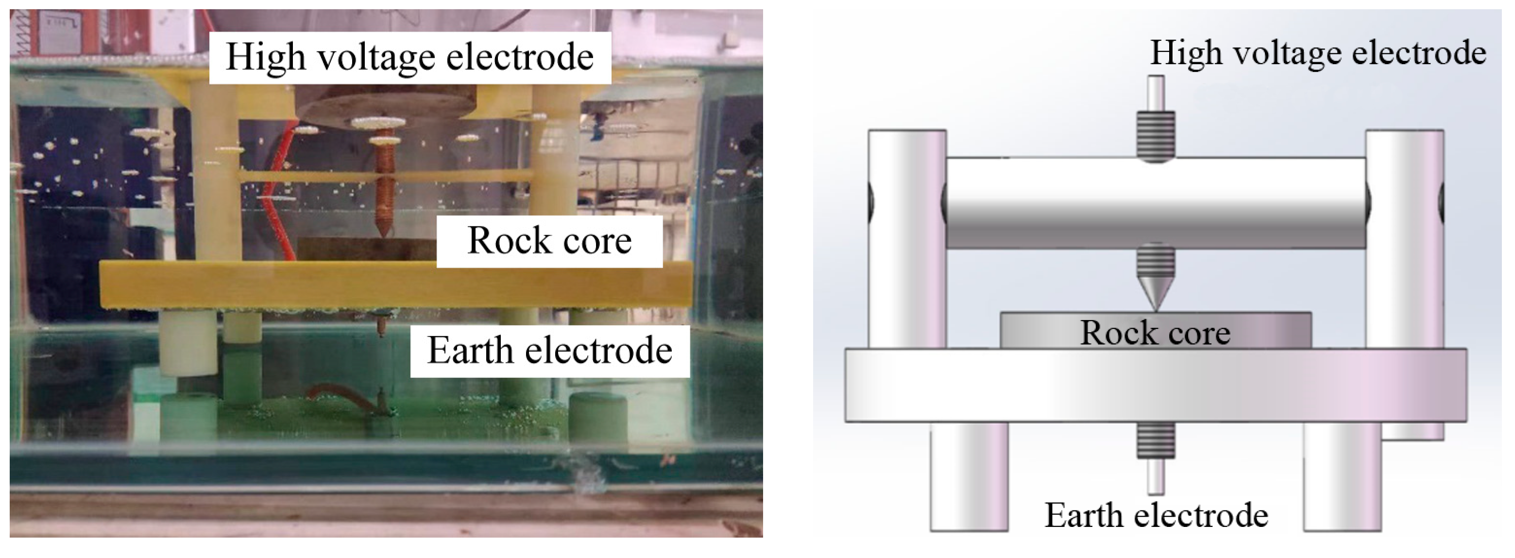
Determining the electric breakdown field strength of rock is the primary consideration of an electric pulse rock-breaking experiment. The experiment mainly uses the coaxial opposite needle electrodes to measure the electric breakdown field strength of rock. As shown in
Figure 19, using transformer oil as an insulating liquid material, immerse the high-voltage electrode, insulating electrode, and rock sample in insulating oil, place the rock between a high-voltage electrode and grounding electrode and keep contact with the electrode at all times, apply a high-voltage electric pulse of different sizes on needle electrode, and record the electric breakdown of rock under single electric pulse. In the experiment, the breakdown probability of rock is defined as
P if the number of times of breaks is
A.
In the experiment, the value of
n is 10. In order to compare the electrical breakdown of rocks with different thicknesses and types, the ratio of voltage amplitude to rock thickness is used as the average EFS of rocks.
where
E means the average EFS of rock;
U denotes the maximum voltage of the electric pulse; and
d represents the rock thickness.
In this experiment, the HVEP power supply adopts the high-voltage electric pulse generator, which is based on the principle of the Marx generator. It adopts the principle of capacitor charging and sparks switch breakdown discharge, and can produce 0–20,000 kV adjustable voltage in an extremely short time.
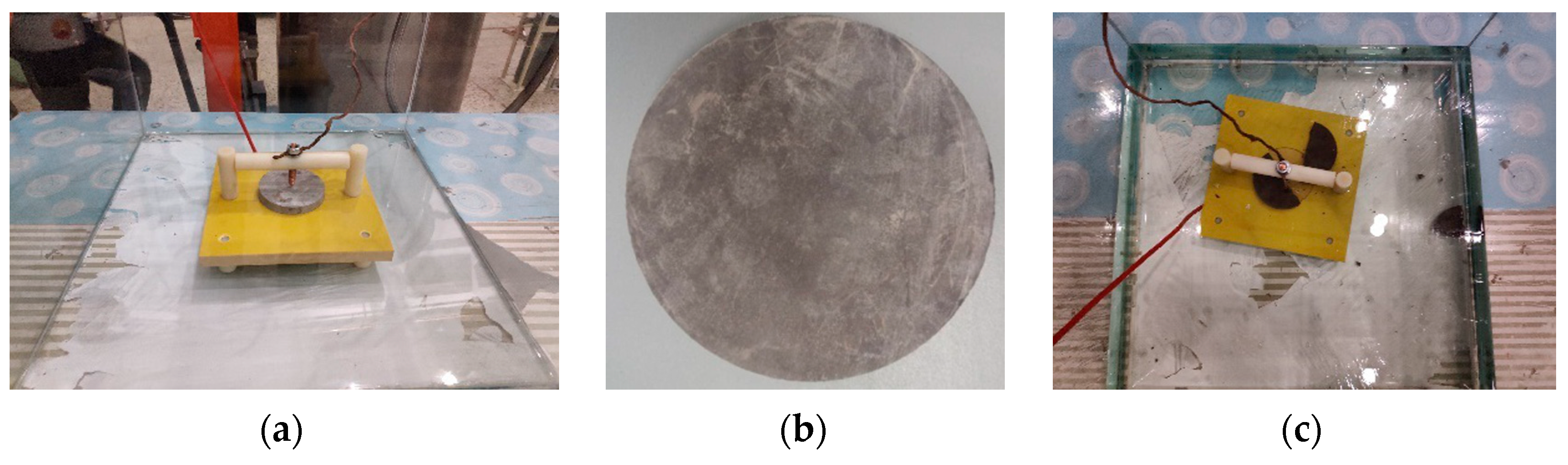
Besides, red copper with good conductivity is selected as the electrode material, and the test fixture is designed as shown in
Figure 20. The electrode and fixture are connected by thread, which is adjustable and can resist falling off under the action of high-voltage electric pulse.
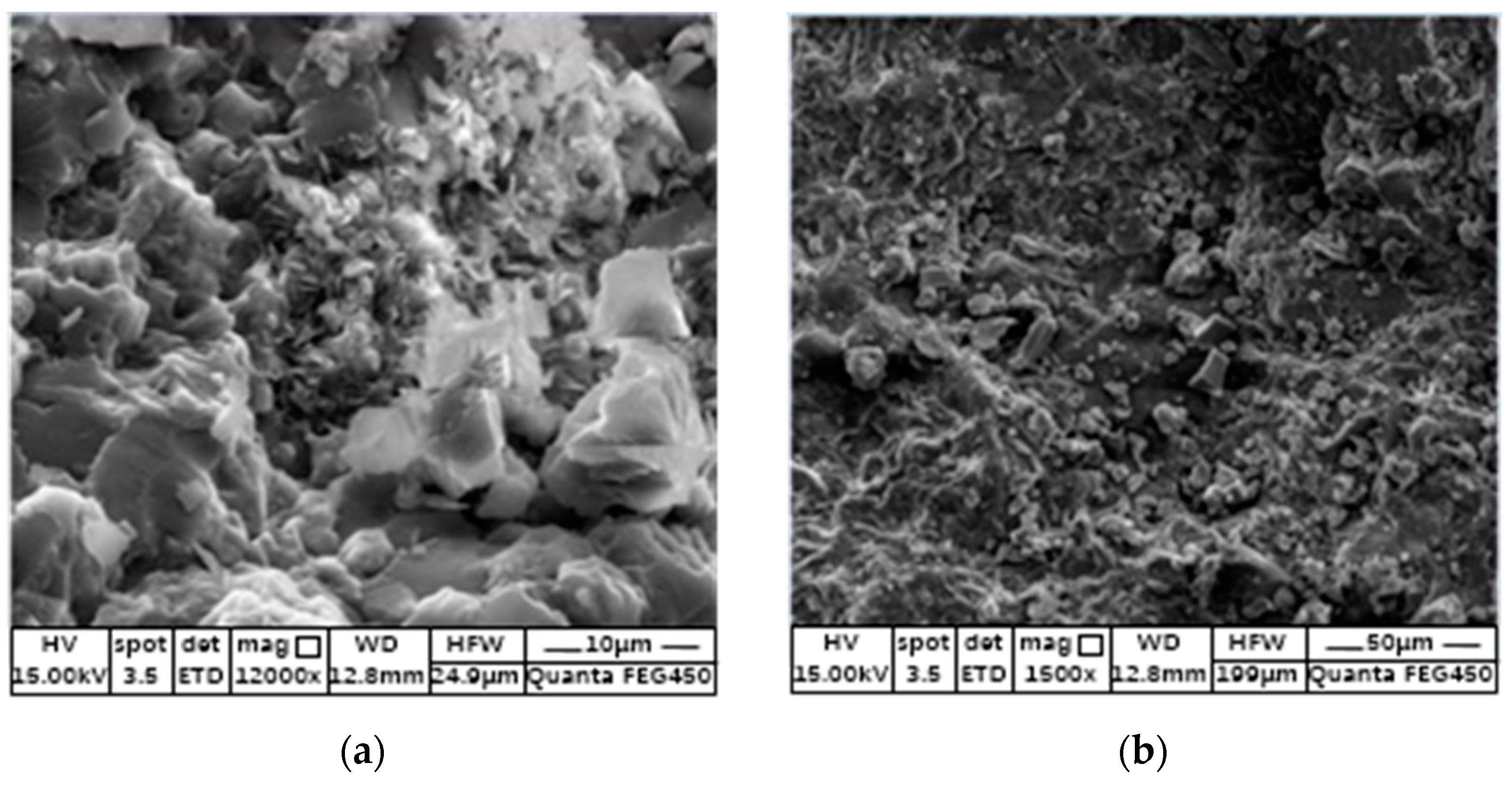
The internal structure of the rock under the electron microscope is shown in
Figure 21a, which shows the internal structure of the sandy conglomerate.
Figure 21b shows the internal structure of purplish red mudstone. It can be seen that the interior of the rock is uneven, and there are some pores at the junction of particles.
In order to measure the average breakdown field strength of rock samples conveniently, and to facilitate the processing of rock samples, the demonstration samples are uniformly made into cylinders with a diameter of 100 mm and a thickness of 10 mm, as shown in
Figure 22 rock samples.
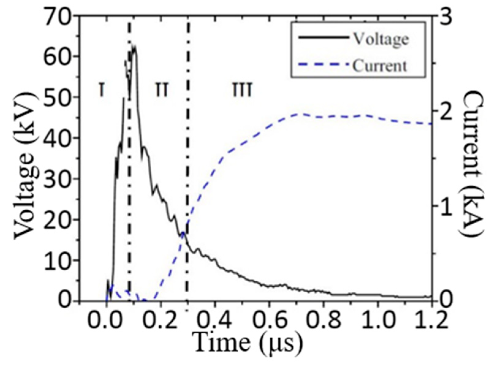
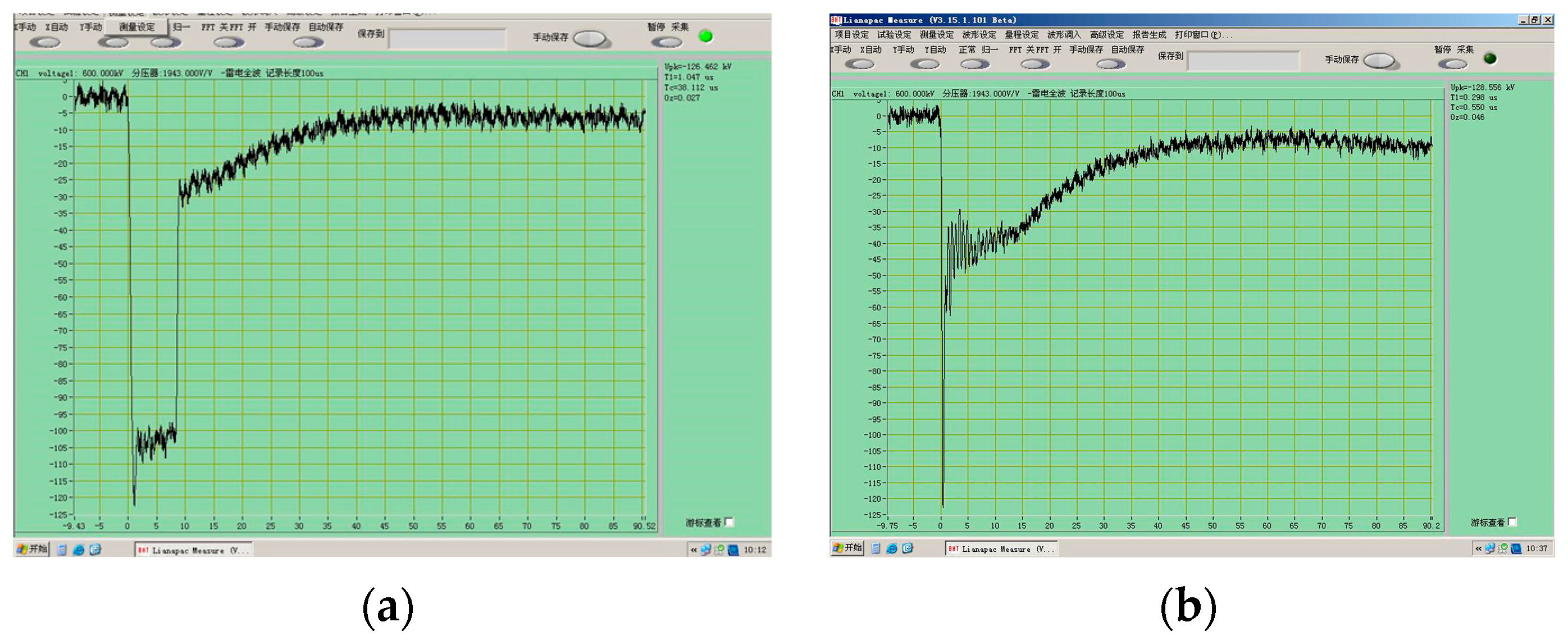
Figure 23 is the typical voltage diagram of rock during the electric breakdown, and
Figure 23a is the voltage waveform of rock that is not broken down under the action of a high-voltage electric pulse. The voltage decreases slowly after rapidly rising to the peak value of 126.462 kV.
Figure 23b shows the voltage waveform of the rock in the process of electrical breakdown. The voltage reaches the peak at 298 ns. When the rock is subjected to electrical breakdown, the internal resistance of the rock decreases rapidly, the voltage decreases rapidly, and rock electrical breakdown is achieved.
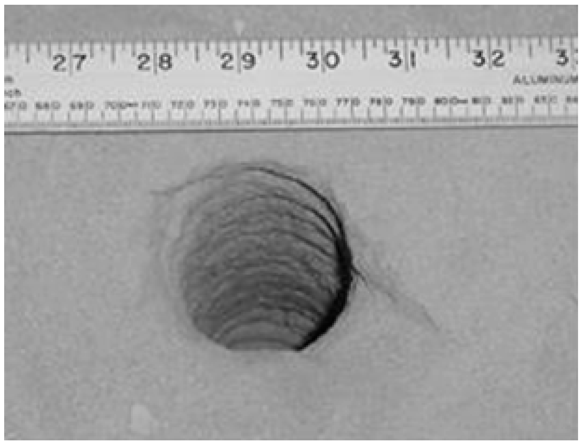
Figure 24 shows two forms of rock after being broken. On the left, the rock is split in two under the action of an electric pulse, and on the right, the rock is cracked under the action of an electric pulse. In both forms, there is an obvious deep pit at the electrode of the electric pulse.


