Article

Study on the Evolution Law of Deep Rock Cracks and the Mechanism of Graded Gradient Support

1
School of Civil Engineering, Henan Polytechnic University, Jiaozuo 454003, China
2
School of Energy and Engineering, Henan Polytechnic University, Jiaozuo 454003, China
3
School of Earth Sciences and Engineering, Hohai University, Nanjing 210098, China
*
Author to whom correspondence should be addressed.
Energies 2023, 16(3), 1183; https://doi.org/10.3390/en16031183
Submission received: 12 December 2022 / Revised: 4 January 2023 / Accepted: 18 January 2023 / Published: 20 January 2023
(This article belongs to the Special Issue Advanced Coal, Petroleum and Nature Gas Exploration Technology)

Abstract

:
The surrounding rock of deep roadway is mostly composed of fractured rock. The deformation of roadway surrounding rock is complicated, which not only involves the stress change, but also involves the support means. This paper aims to study the deformation and fracture evolution law of surrounding rock in deep underground engineering. According to the stress rebalancing characteristics, after roadway excavation, the development and evolution characteristics of surrounding rock cracks are studied. At the same time, different seepage zones are divided according to the relationship between surrounding rock failure and its total stress–strain, that is, complete seepage zone, seepage shielding zone, and proto-rock seepage zone. The crack distribution characteristics of surrounding rock are studied, and the graded control of gradient support is proposed. In the broken area, the gradient bearing shell outside the roadway is achieved by means of bolting and high-strength grouting. As the cracks and pore sizes in the plastic zone gradually decrease along the radial stress direction of the roadway, and the open cracks gradually change into closed cracks, it is difficult for ordinary grouting materials to complete better consolidation and filling. Therefore, small particle size grouting reinforcement materials are studied. The plastic zone (fracture zone) is reinforced with nano-scale grouting material, and the internal three-dimensional gradient bearing shell is formed by combining with the anchor cable. This research plays an important guiding role in the stability of deep roadway surrounding rock.

1. Introduction

With the continuous extension of coal mining depth, the underground mining environment becomes more complicated. After the excavation of deep roadways, the stress of the roadways will change significantly [1,2]. The tangential stress gradually weakens from the outside to the inside and reaches the maximum at the surface, shown as stress concentration. The radial stress increases from the outside to the inside, which is almost zero on the surface, resulting in layered failure of the surrounding rock, tangential force transfer, and further failure of the surrounding rock and crack development [3,4]. Under the influence of high-stress concentration and mining, the surrounding rock can show various cracks. For example, when the surrounding rock cracks develop and have a large opening degree, because of the stress weakening, a large number of cracks with a small opening degree can appear. Moreover, many of these cracks will be isolated and not connected with each other, resulting in poor permeability characteristics of the surrounding rock. The high development of the surrounding rock cracks is bound to reduce its strength, and with the continuous change of stress, it will cause large deformation of roadways and affect the safety of mining production.
Many scholars have studied the stability of roadway surrounding rock control in coal mines. At the same time, a variety of research methods have been used, including theoretical analysis, laboratory testing, etc., and achieved good results [5,6,7]. According to Li et al. [8], large-scale geomechanical models and stress evolution were used to study the deformation characteristics of deep roadway surrounding rock. Zhang et al. [9] studied the excavation and unloading of deep underground tunnels caused by the rupture of surrounding rock and analyzed the fracturing mechanism. Petuknov et al [10] discussed the deformation of surrounding rock after and the failure of stable rock. Alsayed [11] carried out experiments with rock cylinders as specimens and realized true triaxial tests, showing several different failure modes. Kulatilake et al. [12] studied the behavior of jointed rock mass and its failure summary standard. With the development of computer technology, numerical simulation is widely used in the research of coal mining [13,14]. The finite element method (FEM) and finite element difference method (FDM) were used to study roadway stability [15,16,17]. Yang et al. [18] studied the deformation and failure of surrounding rock by combining field investigation, laboratory experiment, and UDEC simulation. Research on the prevention and technology of traditional support, including bolt, anchor cable, and other means, is difficult to meet the control requirements, leading to the softening of coal and rock, resulting in continuous deformation and large-scale movement of surrounding rock [19,20]. Grouting reinforcement can change the shape of surrounding rock to a certain extent, and grouting can fill grout into surrounding rock cracks, improve its cohesion and strength, and further improve the stability of surrounding rock [21,22,23]. The good grouting effect of surrounding rock fissures can ensure that the broken surrounding rock is closely connected together, improve the overall performance of surrounding rock, cement the broken surrounding rock into a complete whole, and even restore to the original rock state to ensure its overall stability.
Under the circumstances of stress redistribution, the surrounding rock structure evolution occurs, which is manifested as obvious crack change from the outside to the inside of the roadway. That is, the cracks close to the roadway are dense and wide, and there are sparse and narrow cracks further inside. The different crack opening causes the traditional grouting method to be unscientific, and the grouting material particles are large, which greatly reduces its injectability and affects the grouting effect, which cannot meet the desired effect. Therefore, this paper studies the regularity and characteristics of the evolution of deep rock cracks through theoretical analysis and expounds the traditional support and reinforcement technology. At the same time, a new type of grouting material is developed, and combined with the characteristics of surrounding rock and cracks, the graded control mechanical model of gradient support is established. According to the gradient failure law, using the gradient control technology, the surrounding rock formed a three-dimensional gradient pressure shell, which restored the bearing capacity of the surrounding rock. The gradient model established in this paper provides a new idea for the control of deep surrounding rock. Meanwhile, the proposed hierarchical control technology ensures the stability of deep surrounding rock and the safety of mining.

2. Study on Evolution Characteristics of Roadway Surrounding Rock Fissure

The surrounding rock fissures are a kind of structural plane in rock mass and exist in large numbers. It is mainly included in primary and secondary fissures. In actual engineering, rock mass with primary fractures is called fractured rock mass when the external force of rock mass is not enough to destroy its strength. Firstly, the primary cracks in the surrounding rock expand, and then secondary cracks appear. At the same time, the primary cracks of the surrounding rock expand, and the secondary cracks continue to develop. The cracks have different opening degrees, and the cracks are connected to each other, which leads to the failure and instability of the rock mass. The surrounding rock fissures of deep roadways are mainly subjected to the action of pressure, and the secondary fissure is one of the common ones, with uneven distribution and large size differences.
Based on previous research results [24], before deep roadway excavation, rock mass is in a three-way stress environment. Once the roadway is excavated, the three-way stress environment of the rock mass will be destroyed. After the excavation and unloading of roadway, the stress field appears to be redistributed. When the stress of the surrounding rock is higher than the elastic limit and enters the plastic state, the surrounding rock will successively appear in the broken zone, the plastic zone, and the elastic zone from the outside. The three corresponding stress–strain stages in the three zones of the surrounding rock are shown in Figure 1. In the figure, R0 is tunnel radius, m, Rf is plastic zone radius, m, and R1 is crushing zone radius, m. In the total stress–strain curve of rock, σs is yield strength, MPa, σpk is peak strength, MPa, and σc is residual strength, MPa.
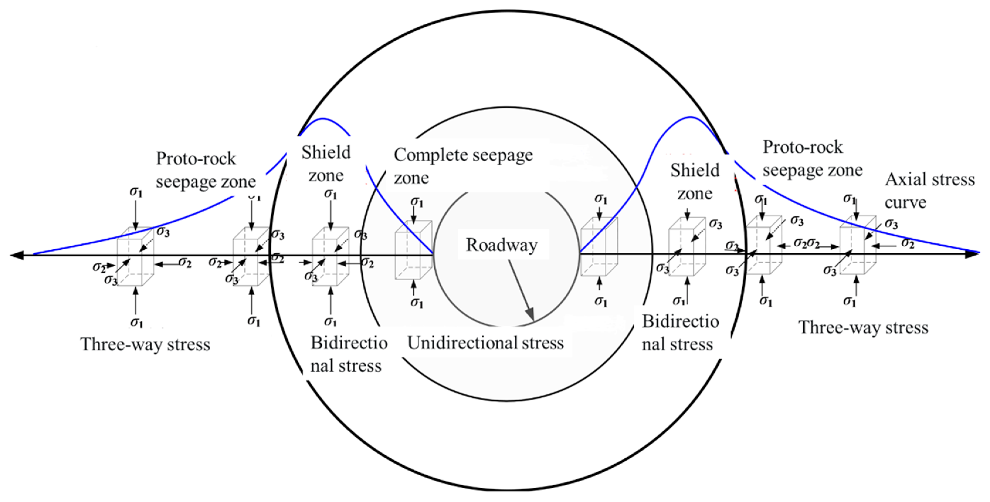
After tunnel excavation, stress on the surrounding rock is redistributed, resulting in unidirectional, bidirectional, and tridirectional states of the surrounding rock from the inside to the outside. At the same time, due to the different degrees of damage caused by the rock mass during the stress process, the rock mass is successively located in the fracture zone, the plastic zone, and the original rock stress zone along the radial direction of the roadway. Corresponding to the stress reduction zone, the stress increase zone, and the proto-rock zone, a relatively obvious hierarchical gradient failure pattern is presented. The gradient failure structure of the surrounding rock is shown in Figure 2. According to the permeability characteristics of each zone [25], it can be divided into complete seepage zone, seepage shielding zone, and proto-rock seepage zone. The fractured zone of the roadway is at the stage of the residual strength of the surrounding rock, and the cracks are large and fully developed, forming a complete seepage zone. The axial and circumaxial permeability of the roadway is equivalent, and the grout can be diffused in all directions. When the roadway enters the plastic zone from the outside to the inside, the permeability of the surrounding rock decreases under the action of the structural plane and it cracks, and the grout is mostly diffused with large cracks. This area is called the directional seepage zone. As the radial depth continues to increase, due to the strengthening of the confining pressure, the cracks are subjected to a compression effect, forming fully developed micro and meso cracks. With the increase of depth, the permeability decreases, and the minimum value is found at the critical point of the plastic and elastic zones, which seriously affects the flow of the grout and forms a seepage shield zone. The permeability of the elastic zone is restored to the state of the original rock, namely the original rock seepage zone. The radial seepage zone of the roadway and its permeability characteristics are finally formed, as shown in Figure 3.

3. Study on Graded Control Mechanism of Gradient Support

3.1. Graded Control Mechanism of Gradient Support

Due to the complexity of deep roadway, there are still a large number of unsolvable scientific problems in roadway management. Traditional support means only combine a variety of support methods, lack the research on the control mechanism of roadways, and do not consider the influence of gradient failure, let alone put forward the control method combined with gradient failure. Therefore, it is difficult to achieve the ideal support control effect. In view of this, combined with the grouting materials developed in this paper, the grouting reinforcement technology is used to put forward a graded control method for gradient support of the surrounding rock, forming a gradient bearing shell model, and the control mechanism is studied in detail. Graded control of gradient support of the surrounding rock mainly refers to adopting corresponding support measures in the corresponding area of the surrounding rock according to the evolution characteristics of the stress gradient of the surrounding rock of the roadway in order to form corresponding gradient support measures in the control area and realize graded control in different areas. For example, the stress gradient in the fracture zone is significant, and high-strength reinforcement materials and bolt support are adopted. While the stress gradient in the plastic zone is weakened, the gradient control is formed step-by-step by adopting the reinforcement material of nanoscale grouting and the anchor cable support.

3.2. Key Ideas of Graded Control for Gradient Support

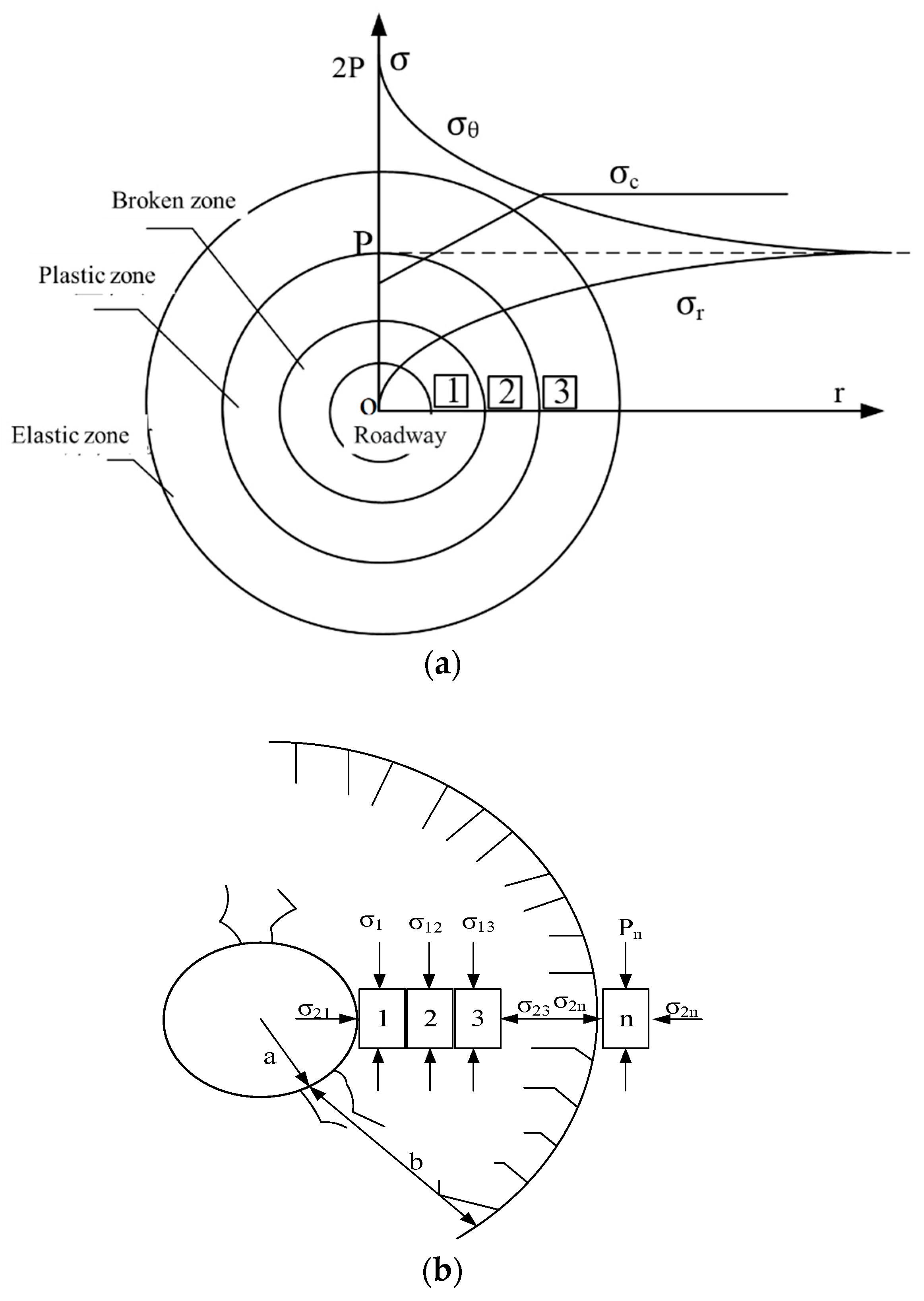
After the excavation of deep roadway, the stress state will change and a stress gradient field will appear in the radial stress direction, resulting in different damage of the surrounding rock from the inside to the outside and finally making the surrounding rock present a typical stress gradient failure mode. When a roadway is excavated, stress concentration will occur, and gradient failure will be more obvious. In particular, when the stress of the deep roadway surrounding rock is greater than the bearing capacity of the rock, it will eventually lead to zoned failure of the surrounding rock, that is, the fracture zone, the plastic zone, and the elastic zone, as shown in Figure 4a. The uniaxial compressive strength of rock, σc, and its variation trend shows the characteristics of increasing zoning, with the lowest strength in the crushing zone and the highest strength in the elastic zone, that is, σc1 < σc2 < σc3. Detailed analysis can be seen in Figure 4b. Element 1 is in the state of primary rock stress before excavation. Once the equilibrium of one side is damaged, the horizontal stress of σ21 will be relieved, and the element will change from three-way stress to two-way stress, or unidirectional stress, and its strength will decrease significantly. At the same time, the stress of the original rock is redistributed, showing stress concentration. If the stress of element 1 (assuming that it is in the crushing zone) is greater than its bearing capacity, the element will be destroyed, and the stress will continue to transfer to the interior of the roadway.
Similarly, the horizontal stress value of element 2 (assuming it is in the plastic zone) is small, and the strength of element 2 is greater than that of element 1, while the failure of element 2 continues, and the stress continues to transfer. During the whole stress process, with the stress transfer, the degree of stress concentration decreases, and the strength of the element gradually increases until the stress of the element n (assuming it is in the elastic zone) and subsequent surrounding rock is less than its bearing capacity. Thus, the element is not damaged, and the original stress condition is maintained. The above analysis shows that, in the whole process of stress transfer, the surrounding rock is subject to similar changes in each direction, and then the surrounding rock of the roadway presents different structural levels of failure.
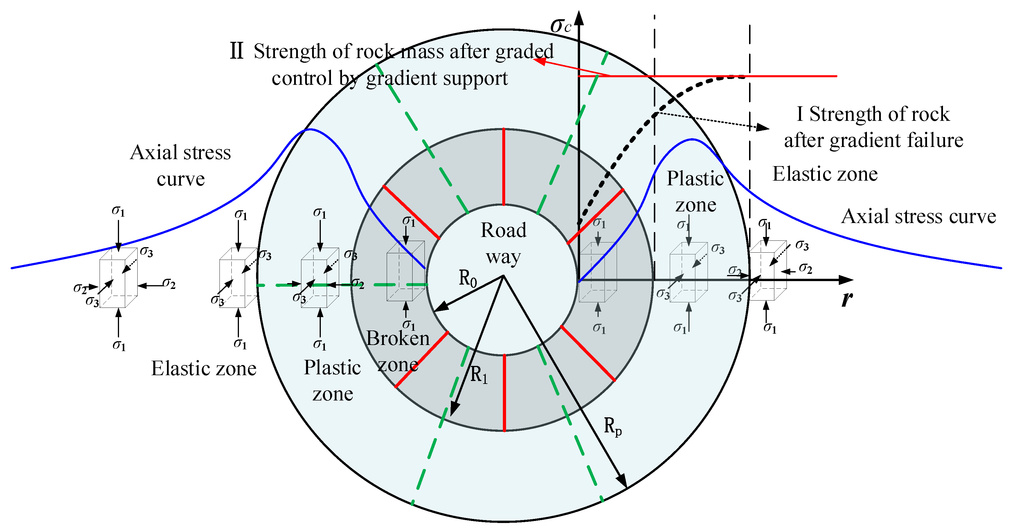
The bearing capacity of rocks in the broken zone and the plastic zone obviously decreases. If no reasonable means of control is taken, the roadway will continue to deform and fail until it becomes unstable. In order to solve the problem of the surrounding rock deformation, the research group, combined with the gradient failure characteristics of the surrounding rock, proposed a graded gradient support control method. In other words, gradient graded support is adopted to realize the integration of the surrounding rock and provides support in the broken zone and the plastic zone. Therefore, the uniformity of the load is controlled by layers to ensure that the strength of the surrounding rock in the broken zone and the plastic zone is restored to the initial stress strength or close to the state of the surrounding rock in the elastic zone, that is, the implementation of the original σc1 < σc2 < σc3 transforms into σ*c1 ≈ σ*c2 ≈ σ*c3.

3.3. Hierarchical Control Principle Model of Gradient Support

The changes of the stress gradient cause the surrounding rock to present unidirectional, bidirectional, and tridirectional stress conditions from the inside to the outside. At the same time, due to the different degrees of damage caused by the rock mass during the stress process, the fracture zone, plastic zone (fracture zone), and elastic zones are formed, showing relatively significant hierarchical gradient failure. The gradient failure leads to a significant reduction in the bearing capacity of the rock mass. If the rock mass is not treated in time under continuous stress, large deformation or even instability of roadway surrounding rock will occur. Therefore, according to the gradient failure, this paper puts forward the graded control method of gradient support to further enhance or even restore the bearing capacity of the rock mass. As shown in Figure 5, curve Ⅰ represents the change rule of rock mass strength caused by gradient failure, while curve Ⅱ represents the ideal change of the rock mass strength after graded control with gradient support. The gradient bearing shell outside the roadway is realized by means of bolting and high-strength grouting. Since the cracks and pore sizes in the plastic zone gradually decrease along the radial stress direction of the roadway, the open cracks also gradually transform into closed cracks. It is difficult for ordinary grouting materials to complete good consolidation and filling, and they still cannot prevent the surrounding rock from developing from the plastic zone to the broken zone. Therefore, in the plastic zone (fractured zone), nano-base grouting materials are used to achieve graded reinforcement, and the internal three-dimensional gradient bearing shell is formed by combining with the anchor cable in order to achieve the transformation from curve I to curve II. The gradient bearing shell includes the broken zone and the plastic zone, which is the gradient support technology corresponding to the stress gradient change established by the pointer and forms the supporting shell with corresponding bearing capacity. We collectively call it the gradient bearing shell [27]. The shell properties formed in the broken zone and the plastic zone are different, in order to distinguish the gradient pressure shell (broken zone) and the gradient pressure shell (plastic zone).

4. Discussion on the Injectivity of Reinforcement Materials

4.1. Traditional Reinforcement Material

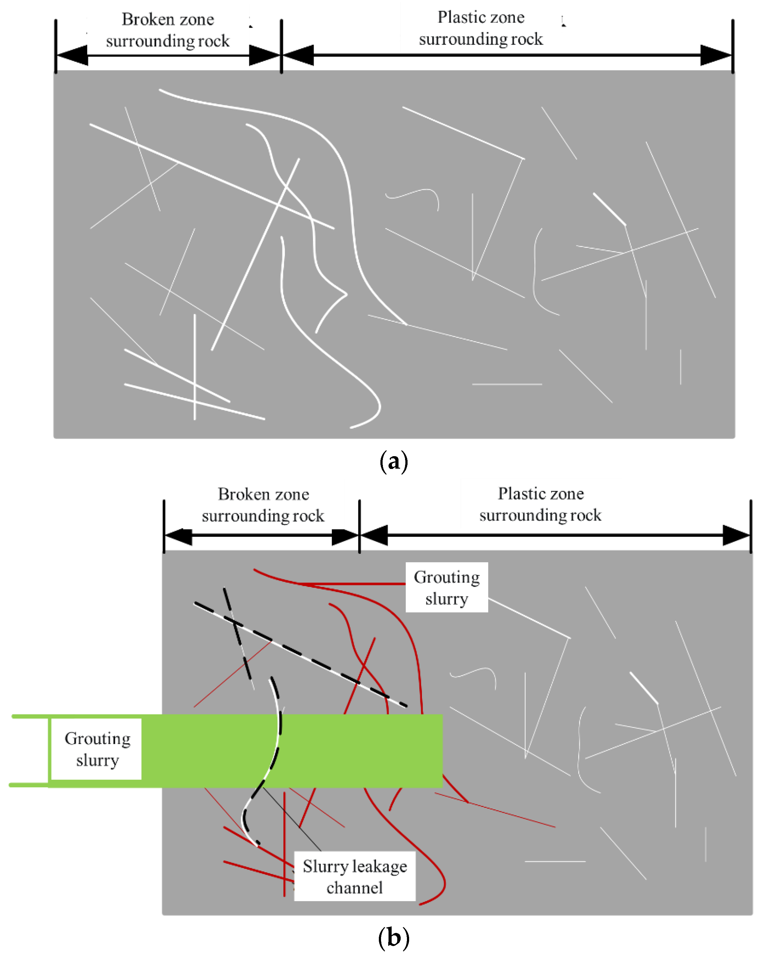
The stress transition caused by roadway excavation leads to the continuous development of surrounding rock cracks, which reduces the strength of the surrounding rock, causing large deformation that seriously affects its stability. The surrounding rock reinforcement can seal the fracture to a certain extent, improve its mechanical properties, and ensure the stable deformation. However, at present, Portland cement is the main material for roadway grouting. However, due to its large particle size, late consolidation cracking, and low grout adhesion, the performance of Portland cement material is greatly weakened in the underground environment with rich water and ion erosion. Combined with the seepage development characteristics of the surrounding rock, it can be seen that the large particle size of traditional materials causes the poor diffusion of grout and the existence of many deep micro-cracks, which leads to the weakening of grout diffusion radius and even causes problems, such as the non-injection of cracks. At the same time, the high grouting pressure method adopted for micro-cracks easily causes the fracture to coalesce, increases the leakage channels, affects the slurry diffusion, and greatly weakens the reinforcement effect. However, the traditional grouting mostly adopts the one-time reinforcement technology, which eventually leads to poor grouting ability and other problems, as shown in Figure 6.
Regarding the injectivity of grout of grouting material, according to the research work completed by scholars, the injectivity standard of grout can be summarized as follows:
The crack opening is Dr, and grout particle size d must meet the formula [29] (1):
D r d > 3
Assuming that the grout can penetrate into the cracks of the injected surrounding rock, the crack opening should meet the following requirements:
D r > 3 d > 0.18   mm
The crack opening of the surrounding rock must meet the conditions of Formula (2); the slurry can be permeated into the filled fissure. However, the change of underground stress leads to the evolution of structure hierarchy of the surrounding rock, which is manifested as obvious crack changes from the outside to the inside of the roadway. That is, the cracks close to the roadway are dense and wide, and sparse and narrow cracks continue to appear inward [30]. This phenomenon shows that not all cracks meet this condition, and micro-cracks (plastic zone cracks) have difficulty with meeting the above requirements, which will inevitably increase the difficulty of grout diffusion, reduce the stability of the surrounding rock after reinforcement, and cause continuous deformation.
The superfine cement material improves the injectivity of the slurry to some extent. Due to the gradient stress, there are many cracks in the plastic zone, and the crack opening is very small, even less than 20 μm, resulting in grout that cannot be injected into the crack. The organic grouting material has good injectivity and high adhesion to the surrounding rock. However, its price is too high, and it pollutes the water, corrodes the human body, and is not natural enough. Therefore, many mines list organic materials as contraband, such as polyurethane and Malisan.
For this reason, the surrounding rock of deep mine reinforcement requires materials with high permeability and high viscosity. High permeability can be achieved by changing the particle size of the material, and high viscosity can be achieved by changing the chemical reaction between the crack and the slurry. When the crack opening is 3 times of the particle size of the reinforcement material, the grout can be injected into the crack. If the difference is greater than 3 times, the grout cannot be injected into the crack and will gradually show a bridging state at the crack mouth. At the same time, considering the complexity of the deep mine environment, it is highly likely to face water-rich and ionic erosion. It is difficult for traditional grouting materials to resist ion erosion, which is bound to cause this. Moreover, even after grouting reinforcement, its performance will be greatly reduced, and it cannot meet the requirements of the surrounding rock control. Therefore, it is necessary to further develop reinforcement materials resistant to ion erosion on the basis of satisfying the filling.

4.2. Graded Control Technology of Gradient Support

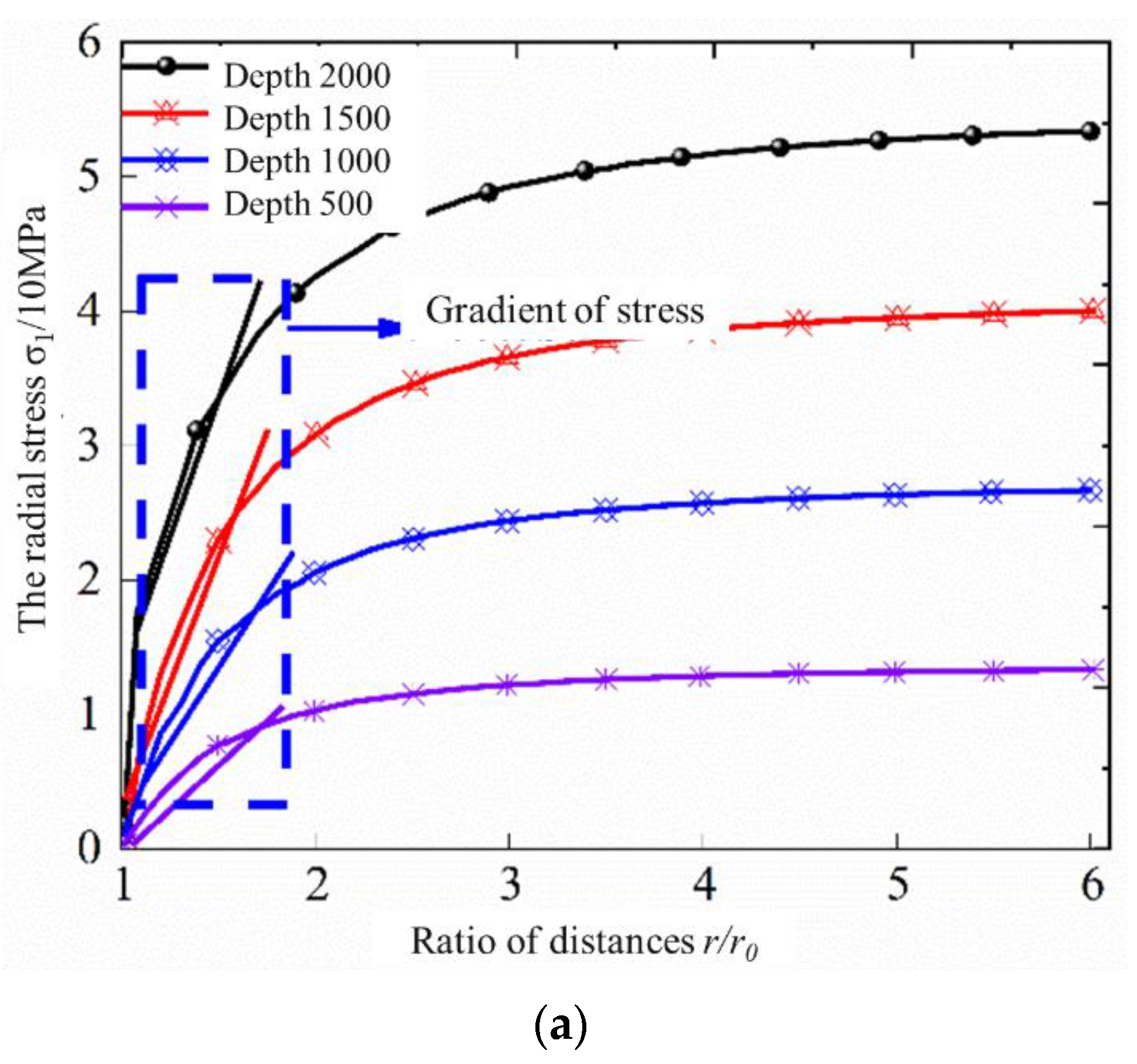
As can be seen from Figure 7, radial stress σr and tangential stress σθ of the surrounding rock are greatly affected after tunnel excavation. The radial stress increased gradually with the increase of distance and was almost zero near the edge of the surrounding rock. However, the tangential stress gradually decreased with the increase of distance and reached its maximum near the edge of the surrounding rock. However, both of them are close to stable at the distance of excavation and are hardly affected by excavation. At the distance of r0–2r0, there was a large difference in stress evolution. The slope of the straight line in the dotted box indicates that the stress of the surrounding rock gradually increased under the influence of the buried depth [30]. The surrounding rock of the deep mining roadway is greatly affected by secondary stress, and the stress gradient field that formed gradually became prominent. There are obvious high stress gradients around deep roadways, which is the main factor leading to the continuous failure of roadways.
At the same time, considering the evolution of the surrounding rock structure caused by gradient failure, the concrete manifestation is that the cracks close to the roadway are dense and wide, and the cracks continue to be sparse and narrow. The traditional grouting materials can only inject cracks with a large crack opening, and micro-cracks cannot reach the injection range. However, for the crack distribution caused by gradient failure of the surrounding rock, the crack opening is small, and there are many cracks in the plastic zone. If the reinforcement cannot be completed, the surrounding rock is bound to be damaged or even unstable. Therefore, this paper studied the small particle grouting reinforcement material, combined with high-strength cement material, and proposed a gradient support classification control method, hoping to improve or even restore the bearing performance of the surrounding rock, that is, the broken area is reinforced by bolt and high-strength grouting. The cracks and pore sizes in the plastic zone gradually become smaller along the radial stress direction of the roadway, and the open cracks also gradually transform into closed cracks. The graded reinforcement is achieved by using nano-based grouting materials, and the internal three-dimensional gradient pressure shell is formed by combining with the anchor cable. After the reinforcement of small particle size grout, all the cracks in the surrounding rock can be filled using multi-scale grading to meet the stability control problem of the surrounding rock. The research work should be further combined with the quantitative characteristics of deep rock cracks, establish a quantitative model, and carry out field tests in other mines in order to make it more suitable for deep, complex geological conditions.

5. Conclusions

According to the gradient failure characteristics of deep roadway surrounding rock, the main conclusions obtained in this paper are as follows:
(1)
After roadway excavation, the stress of the deep surrounding rock is redistributed. Along the radial direction of the roadway, it is divided into stress reduction zone, stress increase zone, and original rock stress zone. According to the permeability characteristics, it can be divided into complete seepage zone, seepage shield zone, and proto-rock seepage zone.
(2)
When the crack opening degree of the surrounding rock meets certain conditions, slurries can permeate into the crack. However, the deep surrounding rock cracks are dense and wide near the roadway, while the deep ones are sparse and narrow. Changing the particle size of the material can improve the grouting ability. If the difference between the particle size of the grouting material and the crack is greater than 3 times, the grouting cannot be injected into the crack, and the bridge state will gradually appear at the crack mouth, greatly reducing the reinforcement effect.
(3)
The equivalent graded gradient support is proposed, and the mechanical model of gradient support is established. The gradient graded support is adopted to achieve the integration of the surrounding rock and provide support to the broken zone and to the plastic zone. Stratified control of load uniformity ensures that the strength of the surrounding rock in the broken zone and the plastic zone is restored to the initial stress strength or close to the state of the surrounding rock in the elastic zone, that is, the implementation of the original σc1 < σc2 < σc3 transforms into σ*c1 ≈ σ*c2 ≈ σ*c3.

Author Contributions

Conceptualization, Z.H.; methodology, Z.L.; formal analysis, F.D.; investigation, Z.C.; data curation, Z.H.; writing—original draft preparation, Z.H. and Z.L.; writing—review and editing, Z.H.; visualization, C.Z. All authors have read and agreed to the published version of the manuscript.

Funding

This study was supported by the Science and Technology Project of Henan Province (222102320004) by Zijie Hong, Central Plains Talent Program—Central Plains Young Top Talent (Central Plains Young Postdoctoral Innovative talent) by Zijie Hong, State and Local Joint Engineering Laboratory for Gas Drainage and Ground Control of Deep Mines (SJF2209) by Zijie Hong, the opening project of Henan Key Laboratory of Underground Engineering and Disaster Prevention (Henan Polytechnic University) by Zijie Hong, Civil Engineering School of young teachers Research ability Enhancement Fund, Henan Polytechnic University by Zijie Hong; Doctoral Fund of Henan Polytechnic University (B2022-25) by Zijie Hong, and the National Natural Science Foundation of China (52174073) by Zhenhua Li. The authors are grateful to the editor and reviewer for discerning comments on this paper.

Institutional Review Board Statement

The study did not require ethical approval.

Informed Consent Statement

Informed consent was obtained from all subjects involved in the study.

Data Availability Statement

Data will be provided upon request to the corresponding author.

Conflicts of Interest

The authors declare no conflict of interest.

References

  1. Bai, E.; Guo, W.; Tan, Y. Negative externalities of high intensity mining and disaster prevention technology in China. Bull. Eng. Geol. Environ. 2019, 78, 5219–5235. [Google Scholar] [CrossRef]
  2. Huang, Q.; He, W. Research on overburden movement characteristics of large mining height working face in shallow buried thin bedrock. Energies 2019, 12, 4208. [Google Scholar] [CrossRef] [Green Version]
  3. He, M.C.; Xie, H.P.; Peng, S.P.; Jiang, Y.D. Study on rock mechanics in deep mining engineering. Chin. J. Rock Mech. Eng. 2005, 24, 2803–2813. [Google Scholar]
  4. Chen, J.; Zhao, J.; Zhang, S.; Zhang, Y.; Yang, F.; Li, M. An experimental and analytical research on the evolution of mining cracks in deep floor rock mass. Pure Appl. Geophys. 2020, 177, 5325. [Google Scholar] [CrossRef]
  5. Yin, Q.; Wu, J.Y.; Jiang, Z.; Zhu, C.; Su, H.; Jing, H.; Gu, X. Investigating the effect of water quenching cycles on mechanical behaviors for granites after conventional triaxial compression. Geomech. Geophys. Geo-Energy Geo-Resour. 2022, 8, 77. [Google Scholar] [CrossRef]
  6. Liu, C.; Yang, Z.; Gong, P.; Wang, K.; Zhang, X.; Zhang, J.; Li, Y. Accident analysis in relation to main roof structure when longwall face advances toward a roadway: A case study. Adv. Civ. Eng. 2018, 2018, 3810315. [Google Scholar] [CrossRef] [Green Version]
  7. Yu, W.; Pan, B.; Zhang, F.; Yao, S.; Liu, F. Deformation characteristics and determination of optimum supporting time of alteration rock mass in deep mine. KSCE J. Civ. Eng. 2019, 23, 4921–4932. [Google Scholar] [CrossRef]
  8. Ren, D.Z.; Wang, X.Z.; Kou, Z.H.; Wang, S.; Wang, H.; Wang, X.; Tang, Y.; Jiao, Z.; Zhou, D.; Zhang, R. Feasibility evaluation of CO2 EOR and storage in tight oil reservoirs: A demonstration project in the Ordos Basin. Fuel 2023, 331, 125652. [Google Scholar] [CrossRef]
  9. Wang, Y.; Zhu, C.; He, M.C.; Wang, X.; Le, H.L. Macro-meso dynamic fracture behaviors of Xinjiang marble exposed to freeze thaw and frequent impact disturbance loads: A lab-scale testing. Geomech. Geophys. Geo-Energy Geo-Resour. 2022, 8, 154. [Google Scholar] [CrossRef]
  10. He, M.; Sui, Q.; Li, M.; Wang, Z.; Tao, Z. Compensation Excavation Method Control for Large Deformation Disaster of Mountain Soft Rock Tunnel. Int. J. Min. Sci. Technol. 2022, 5, 951–963. [Google Scholar] [CrossRef]
  11. Alsayed, M.I. Utilising the Hoek triaxial cell for multriaxial testing of hollow rock cylinders. Int. J. Rock Mech. Min. Sci. 2002, 39, 355–366. [Google Scholar] [CrossRef]
  12. Kulatilake, P.H.S.W.; Park, J.; Malama, B. A new rockmass failure criterion for biaxial loading conditions. Geotechnol. Geol. Eng. 2006, 24, 871–888. [Google Scholar] [CrossRef]
  13. Unver, B.; Yasitli, N.E. Modelling of strata movement with a special reference to caving mechanism in thick seam coal mining. Int. J. Coal Geol. 2006, 66, 227–252. [Google Scholar] [CrossRef]
  14. Ju, Y.; Wang, Y.; Su, C.; Zhang, D.; Ren, Z. Numerical analysis of the dynamic evolution of mining-induced stresses and fractures in multilayered rock strata using continuum based discrete element methods. Int. J. Rock Mech. Min. Sci. 2019, 113, 191–210. [Google Scholar] [CrossRef] [Green Version]
  15. Duan, B.; Xia, H.; Yang, X. Impacts of bench blasting vibration on the stability of the surrounding rock masses of roadways. Tunnel. Undergr. Space Technol. 2018, 71, 605–622. [Google Scholar] [CrossRef]
  16. Yu, W.; Liu, F. Stability of close chambers surrounding rock in deep and comprehensive control technology. Adv. Civ. Eng. 2018, 2018, 6275941. [Google Scholar] [CrossRef]
  17. Liu, C. Research on deep-buried roadway surrounding rock stability and control technology. Geotech. Geol. Eng. 2018, 36, 3871–3878. [Google Scholar] [CrossRef]
  18. Bao, Y.D.; Chen, J.P.; Su, L.J.; Zhang, W.; Zhan, J. A novel numerical approach for rock slide blocking river based on the CEFDEM model: A case study from the Samaoding paleolandslide blocking river event. Eng. Geol. 2023, 312, 106949. [Google Scholar] [CrossRef]
  19. Kang, H.P.; Wang, G.F.; Jiang, P.F.; Wang, J.C.; Zhang, N.; Jing, H.W.; Huang, B.X.; Yang, B.G.; Guan, X.M.; Wang, Z.G. Conception for strata control and intelligent mining technology in deep coal mines with depth more than 1000 m. J. China Coal Soc. 2018, 43, 1789–1800. [Google Scholar]
  20. Xie, H.; Peng, S.; He, M. Basic Theory and Engineering Practice in Deep Mining; Science Press: Beijing, China, 2005; pp. 1–35. [Google Scholar]
  21. Nikbakhtan, B.; Osanloo, M. Effect of grout pressure and grout flow on soil physical and mechanical properties injet grouting operations. Int. J. Rock Mech. Min. Sci. 2009, 46, 498–505. [Google Scholar] [CrossRef]
  22. Hong, Z.; Zuo, J.; Zhang, Z.; Liu, C.; Liu, L.; Liu, H.Y. Effects of nano-clay on the mechanical and microstructural properties of cement based grouting material in sodium chloride solution. Constr. Build. Mater. 2020, 245, 118420. [Google Scholar] [CrossRef]
  23. Varol, A.; Dalgic, S. Grouting applications in the Istanbul metro, Turkey. Tunnel. Undergr. Space Technol. 2006, 21, 602–612. [Google Scholar] [CrossRef]
  24. Wang, H.; Li, H.; Tang, L.; Ren, X.; Meng, Q.; Zhu, C. Fracture of two three-dimensional parallel internal cracks in brittle solid under ultrasonic fracturing. J. Rock Mech. Geotech. Eng. 2022, 14, 757–769. [Google Scholar] [CrossRef]
  25. Zhang, N.; Xu, X.L.; Li, G.C. Fissuere-evolving laws of surrounding rock mass of roadway and control of seepage disasters. Chin. J. Rock Mech. Eng. 2009, 28, 331–335. [Google Scholar] [CrossRef]
  26. Dong, F. Support Theory and Application Technology of Roadway Surrounding Rock Loose Zone; China Coal Industry Press: Beijing, China, 2001; pp. 20–45. [Google Scholar]
  27. Zuo, J.P.; Hong, Z.J.; Yu, M.L.; Liu, H.Y.; Wang, Z.B. Research on gradient support model and classification control of broken surrounding rock. J. China Univ. Min. Technol. 2022, 51, 221–231. [Google Scholar]
  28. Zhang, Z. Study on the Mechanism of Grouting Reinforcement of Weak Medium Filling Cracks. Ph.D. Dissertation, Shangdong University, Jinan, China, 2015. [Google Scholar]
  29. Guo, Y.; Zhang, B.L.; Zheng, X.G.; Zhou, W.; Wei, X.L.; Zhu, D.X. Grouting reinforcement technology of superfine cement with wind oxidation zone based on time-varying rheological parameters of slurries. J. Min. Saf. Eng. 2019, 36, 339–344. [Google Scholar]
  30. Zuo, J.P.; Wei, X.; Wang, J.; Liu, D.J.; Cui, F. Investigation of failure mechanism and model for rocks in deep roadway under stress gradient effect. J. China Univ. Min. Technol. 2018, 47, 478–485. [Google Scholar]
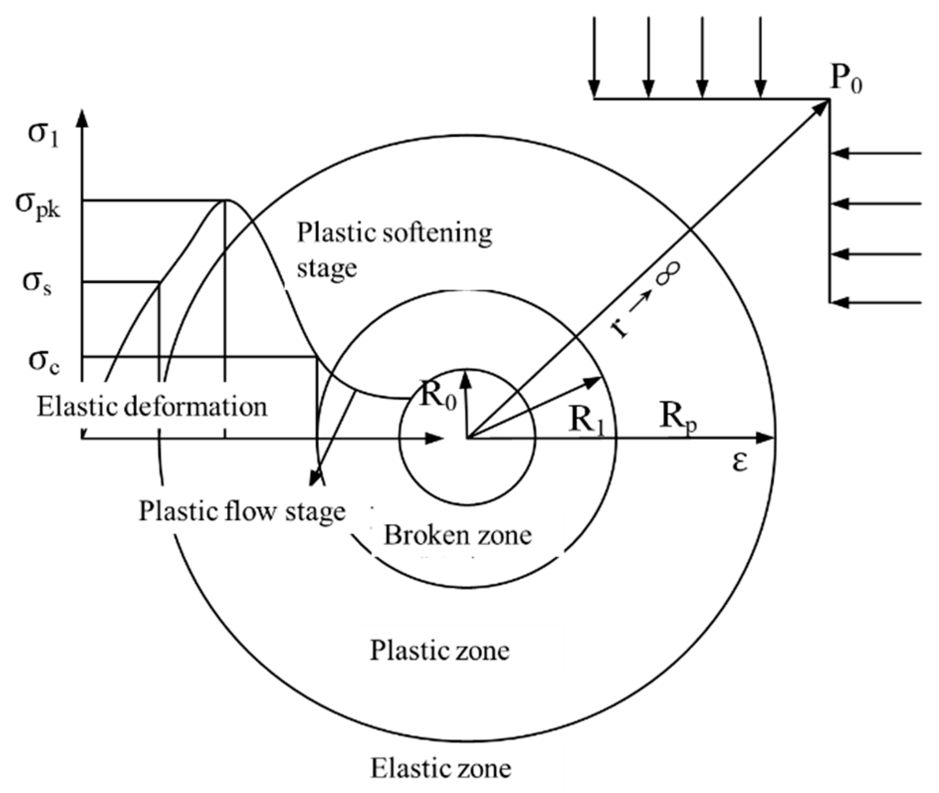
Figure 1. Surrounding rock zoning and rock stress–strain curve model of circular roadway.
Energies 16 01183 g001
Figure 2. Schematic diagram of gradient failure structure of surrounding rock.
Energies 16 01183 g002
Figure 3. Radial seepage development characteristics of surrounding rocks.
Energies 16 01183 g003
Figure 4. Mechanical model after roadway excavation; (a) Mechanical model of surrounding rock; (b) Stratified failure of surrounding rock physical state [26].
Energies 16 01183 g004
Figure 5. Mechanical model of graded support control.
Energies 16 01183 g005
Figure 6. Chematic diagram of traditional grouting [28]. (a) Without grouting in surrounding rock; (b) traditional grouting in surrounding rock.
Energies 16 01183 g006
Figure 7. Distribution diagram of surrounding rock stress after roadway excavation. (a) The radial stress; (b) The tangential stress.
Energies 16 01183 g007aEnergies 16 01183 g007b
Disclaimer/Publisher’s Note: The statements, opinions and data contained in all publications are solely those of the individual author(s) and contributor(s) and not of MDPI and/or the editor(s). MDPI and/or the editor(s) disclaim responsibility for any injury to people or property resulting from any ideas, methods, instructions or products referred to in the content.