2.1. Optical Concentrator for Small-Size CSP Applications
The linear Fresnel reflectors make use of the Fresnel lens effect, being constituted by a concentrating mirror with a large aperture and a relatively short focal length. Typically, the reflectors are located at the base of the whole system, remaining very close to the supporting structure. Therefore, they are less subject to actions by the wind and other atmospheric agents and have a lighter structure. Furthermore, only a single actuator is needed for sun tracking. Consequently, also the support structure of the mirrors and the receiver is much lighter, which allows a Fresnel system to be placed even on roofs (industrial and residential) and coverings. However, this linear system does not allow for achieving a relatively high concentration ratio. To increase the temperature on the receiver, the development of a novel Fresnel concentrating optics is necessary, which can cope with the opposite requirements of a relatively high concentration ratio, simplicity, lightness, cost-effectiveness, and low soil occupancy.
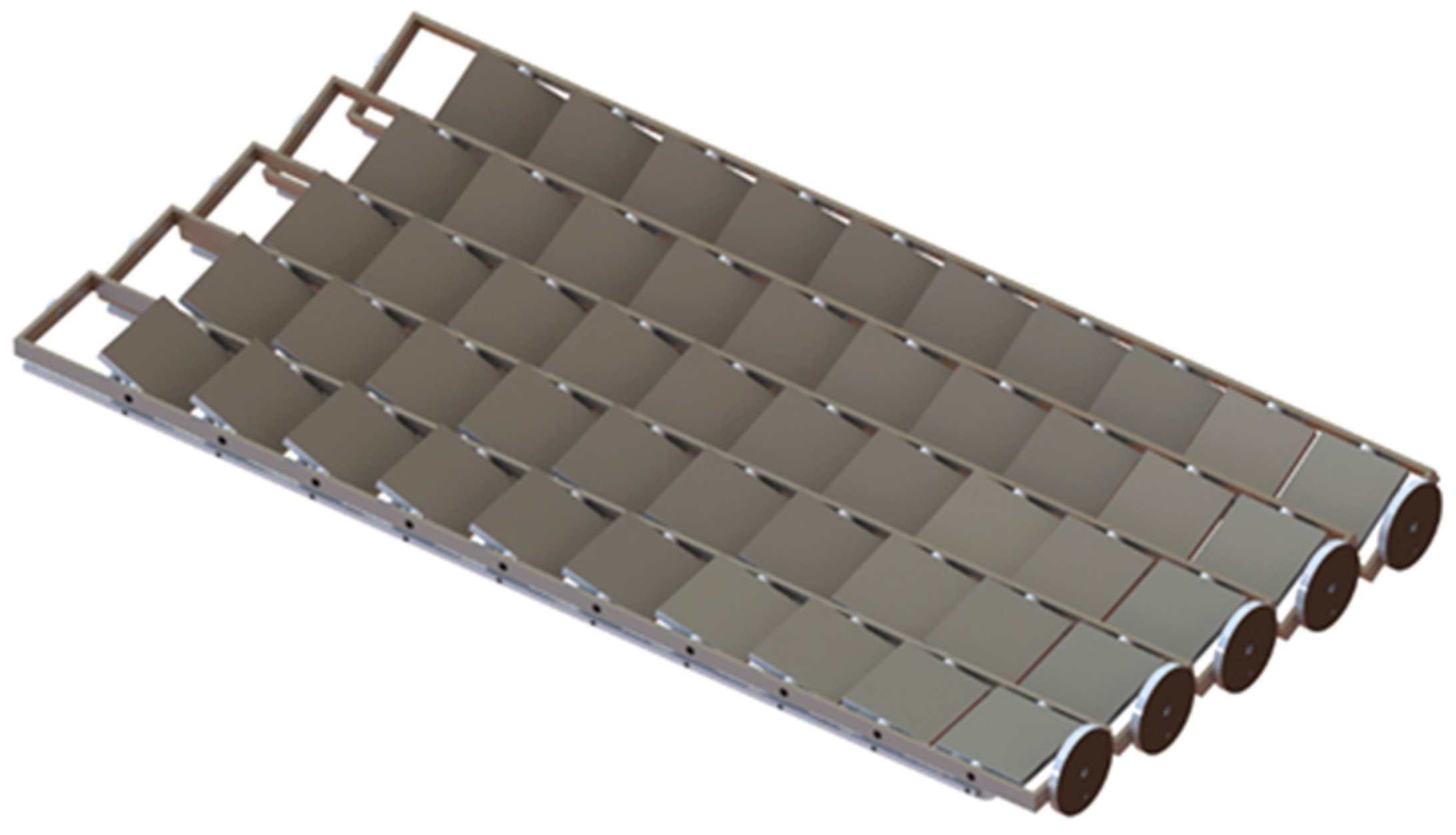
For CSP plants with a capacity of up to 1 MW, a Bi-Axial Fresnel (BAF) lens system can be considered able to meet all the requirements. A BAF system is constituted by a two-axes concentrator consisting of flat or slightly curved mirrors. The concentrator is constituted of an array of pivoting frames (
Figure 1), each one carrying a plurality of mirrors. The frames can be simultaneously pivoted by a single actuator by means of a mechanical linkage.
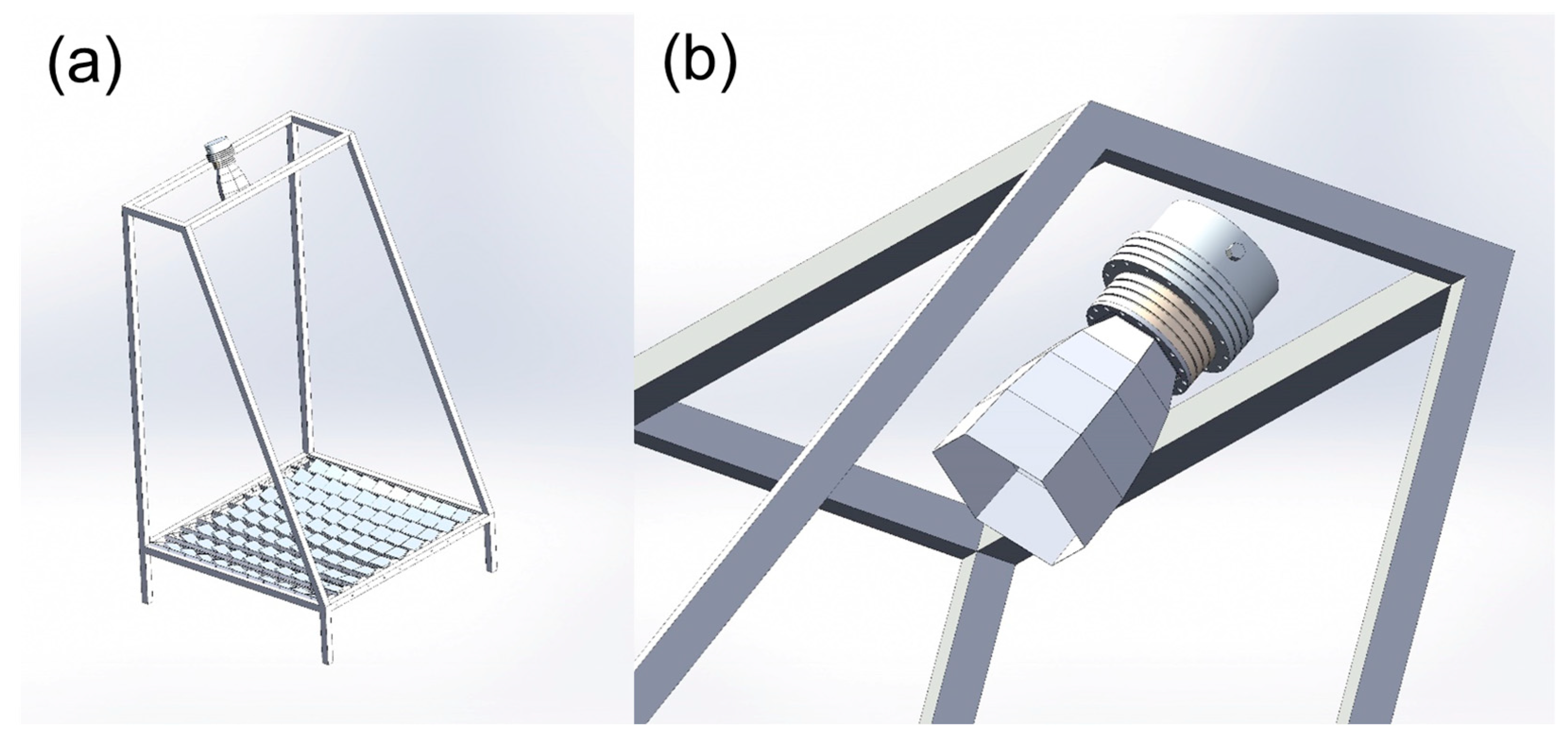
The similarity of this concept with the conventional Fresnel system is straightforward. In this case, however, the mirrors can be rotated along an axis perpendicular to the axis of the frames. A bi-axial movement is then achieved, with a much-reduced number of servo motors with respect to a conventional bi-axial concentrator, which usually requires two motors per mirror. The precision of the scheme is obviously lower than a full bi-axial system, but its lower cost makes this kind of concentrating optics more suited to small-scale systems. A secondary concentrator can be accommodated in the assembly to both partly compensate for the optical inaccuracies and to further increase the concentration. The concentration ratio is roughly the square of a conventional single-axis Fresnel, thereby allowing a higher operating temperature than traditional Fresnel systems. A much smaller receiver is needed and the cost of the target supporting structure can be reduced as well. An example of the solar concentrator/secondary mirror/receiver is depicted in
Figure 2.
The design of practical BAF concentrating optics has been defined by establishing the basic parameters reported in
Table 1. With the aim to be conservative in the estimation of the costs and the overall performance, a value of 0.6 for the optical efficiency is considered, that is a value condensing the optical losses of primary and secondary mirrors. The reflective area of the single mirror is fixed to 1.05 × 1.05 m
2, defined to be the maximum size preserving from problems of structure mechanical stability in the case of extremely harsh weather conditions.
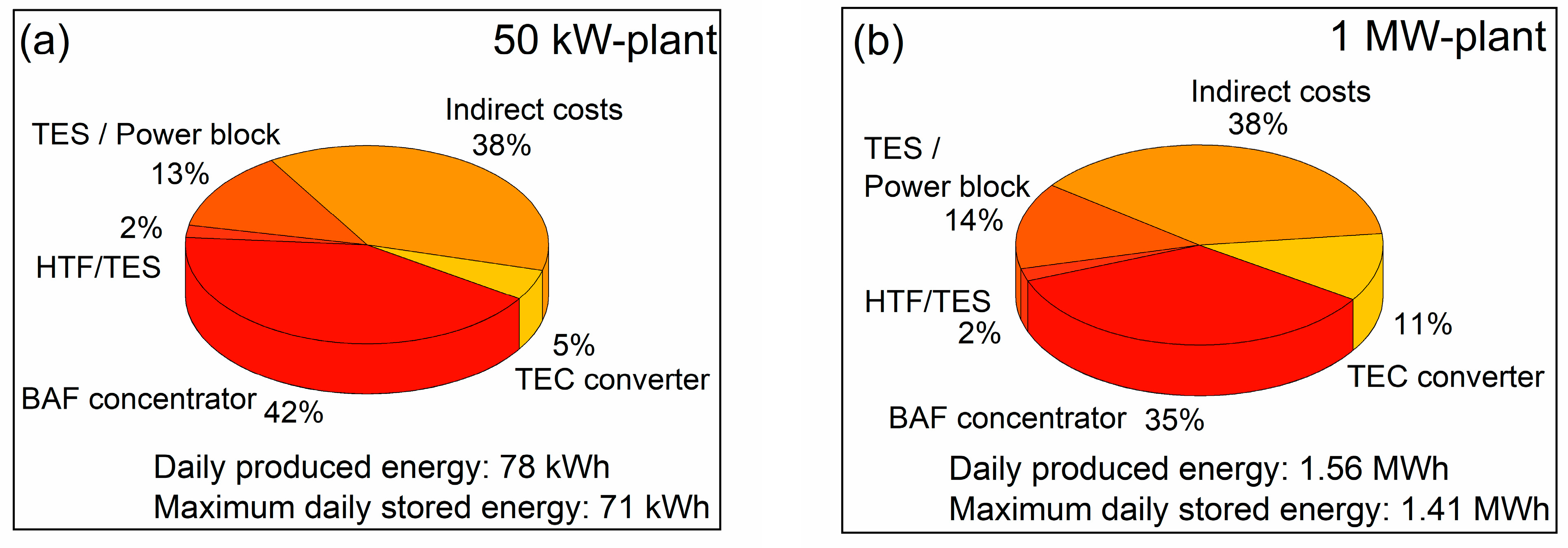
Based on these assumptions, the number of BAF mirrors can be sized according to the input power capacity (from 50 kW to 1 MW) by fixing a constant input power density on the receiver (Pin = 902 kW/m2). To accomplish such a technological challenge, the secondary mirror is characterized by a decreasing concentration ratio as a function of the plant size, reaching a maximum value of 20 suns. The number of servo motors actuating the sun-tracker depends on the number of necessary mirrors’ rows. The receiver is modeled to have a circular shape, the diameter of which is limited to values << 1.5 m, considered as the maximum value to obtain a homogenous surface radiation distribution with the employed optics.
Table 2 reports all the main features of the system according to the 5 different sizes of the CSP plant. The total cost of the system, expressed in EUR/kW (i.e., cost of power) or in EUR/m
2 (allowing to establish the soil occupation at a given plant capacity), has been calculated considering the commercially available materials’ costs. An overhead of 35% on the operating costs has been applied to the total direct costs for contemplating possible extra charges in the processing costs. Even if a direct comparison with CSP cannot be made since CSP plants at small scales are not fully investigated, the estimated costs (details are in
Appendix A) are lower than 120–280 EUR/m
2 which is the range reported for plants larger than 50 MW of electrical production [
13]. Moreover, the materials’ costs could be even lower if large-scale production of the system will occur. Finally, it is worth noticing that the soil occupancy is far lower than the more consolidated technologies operating at high receiver temperatures, being 3300 m
2/MW for the 1 MW input power capacity plant. The use of parabolic trough collector systems is reported in the order of at least 6100 m
2/MW for the solar field area [
14], which is about double that of a BAF concentrator system.
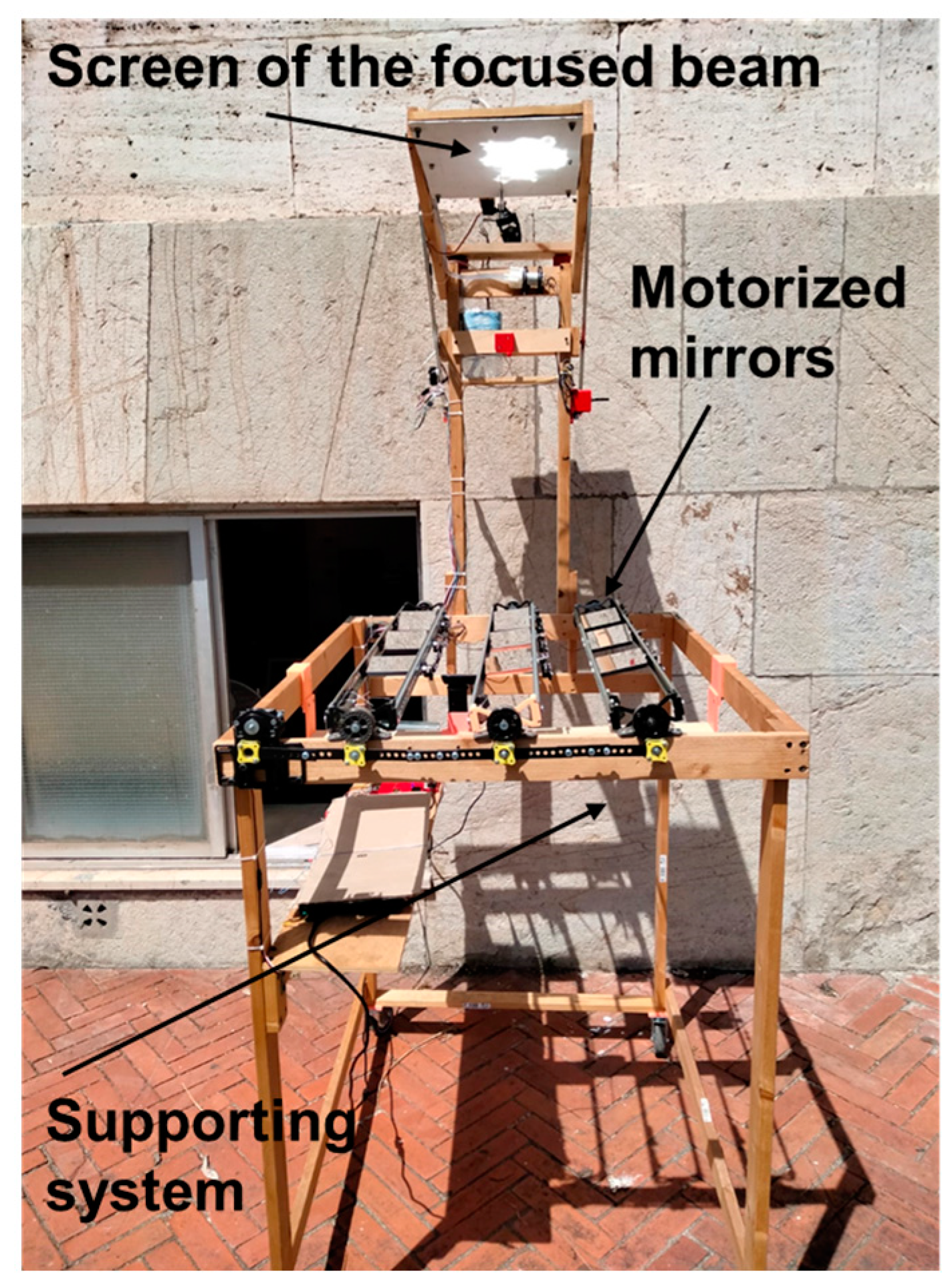
A very elementary, lab-scale prototype was developed and built (
Figure 3) for the first experimental campaign, which is currently in progress. In the picture, it is possible to observe the concentrated beam impinging the monitoring screen on the top, whereas the movement system with the mirrors is located at the bottom of the prototype.
2.2. TECs as CSP Engineered Receiver
The integration of a TEC in CSP plants can improve the overall conversion efficiency of the whole system, since a TEC receiver can efficiently absorb the concentrated sunlight, similarly to the state-of-the-art receivers, and produce an additional quantity of electricity, notwithstanding it can feed a secondary electrical or thermal stage. This is possible since the architecture of a TEC is constituted by an electrode (cathode) acting as both absorber and electrons’ emitter, which operates at a temperature
TC that is much higher than the temperature
TA of the second electrode (anode). Besides establishing the Carnot limit, the difference between
TC and
TA defines the maximum performance of the converter and depends on the thermally conductive and radiative energy fluxes within the converter. Moreover, the two electrodes must be separated by small gaps estimated to be in the range 0.3–3 µm [
15,
16] to maximize the TEC conversion efficiency, since small gaps avoid space charge effects limiting the device current and too small gaps induce near-field conditions causing anode overheating. To accomplish it, many strategies were pursued but the use of solid dielectric microspacers (DMS) seems to be the most challenging but practical solution. Recently, the use of zirconia DMS arranged in a specific pattern was demonstrated in practical thermionic-based applications up to 1350 °C [
17]. According to the thermal simulations, a thermal gradient of about 700 °C when the cathode is impinged by an input radiative flux of 90 W/cm
2 can be established under optimized conditions.
If the anode, cathode, and absorber have the same active area, the TEC conversion efficiency
ηTEC can be defined as:
where
JTEC is the net thermionic current density and
VOUT is the output voltage, which, under ideal operating conditions, is the difference between the cathode work function (Φ
C) and the anode one (Φ
A) divided by the electron charge
q.
JTEC is the difference between the cathode current density and the anode one:
where
JTI,C and
JTI,A are the cathode and anode current densities at the voltage
VOUT, respectively.
The thermionic saturation current density
JTI for the two electrodes is equal to:
where
AR is the Richardson constant,
T the temperature, Φ the work function of each electrode, and
kB is the Boltzmann constant.
To evaluate the performance of the TEC as a conversion topping cycle for small-size CSP plants, the analytic model implemented in a previous work [
9] is here employed, in order to take into account the thermal fluxes losses (emissive, conductive, ohmic, and thermionic cooling losses) involved in the process. Some realistic assumptions are made: (1) the input solar flux is fixed to 90.2 W/cm
2; (2) the cathode and the anode substrates are molybdenum (Mo) and copper (Cu), respectively; (3) thermally and chemically stable thin-films are applied on both the cathode and the anode substrates’ inner surface, to form the thermionic emitter and collector, respectively, and suitably engineering the electrodes’ work functions; (4) the optical properties of such thin-films are considered not to affect the thermal balance equations in the thermo-radiative contributions; (5) the maximum achievable cathode temperature is 1400 °C; (6) the maximum achievable temperature difference between the electrodes is 700 °C; (7) the anode temperature
TA is a free parameter, that corresponds to the case of complete control of heat extraction from the anode; (8) no space charge conditions occur, therefore the device operates under ideal electron transport conditions.
The physical properties used in the model are resumed in
Table 3. As in the case of the BAF concentrator design, a conservative approach is applied for the evaluation of the TEC performance by considering a value of A
R for the emitter which is half of the ideal value (contrarily to that of the anode, considered as 120 A cm
−2K
−2). As regards the optical properties of the cathode, a constant spectral selectivity α/ε of 2.42 is considered a function of temperature, with a solar absorptance α of 88% and a thermal emittance of 35%. These values can be obtained by applying a surface nanostructuring that enhances the absorber material’s optical properties, as already reported for other ceramic absorbers [
18,
19].
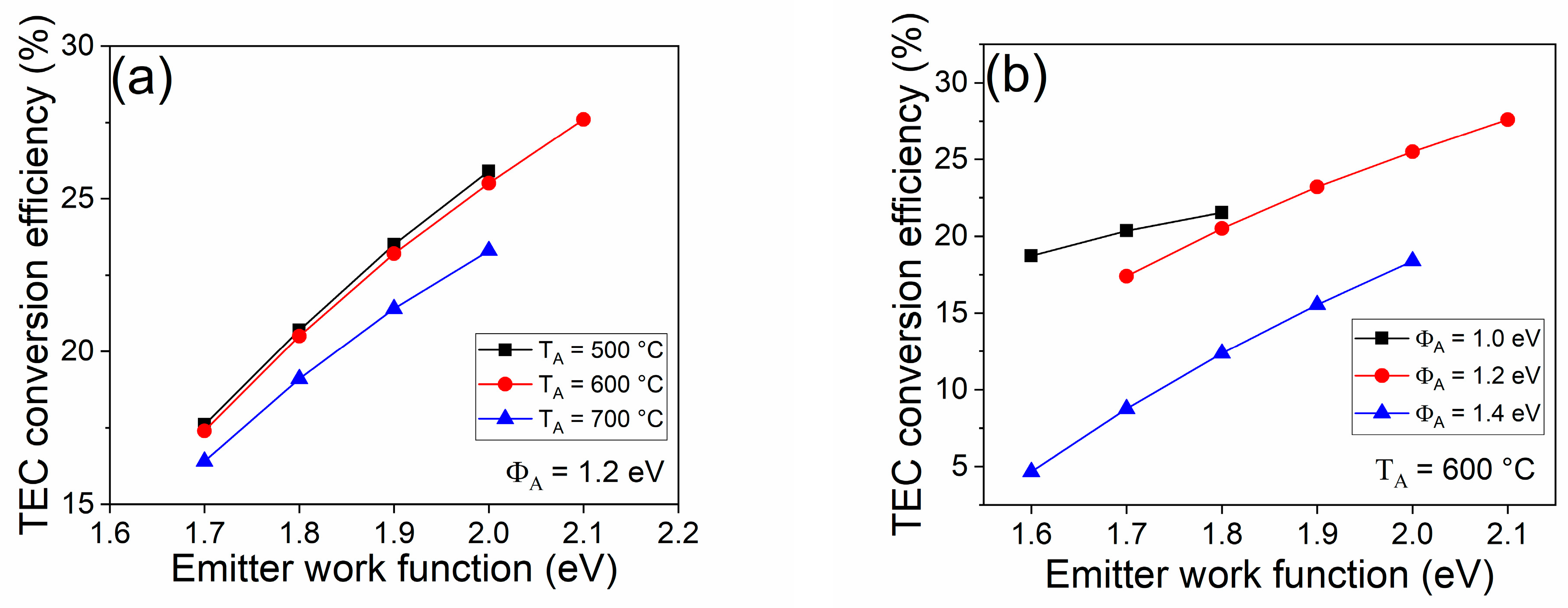
Figure 4a shows the values of the TEC conversion efficiency obtained as a function of the emitter work function for different
TA values at fixed anode work function Φ
A = 1.2 eV.
Figure 4b shows the efficiency obtained as a function of the emitter work function by varying the Φ
A values from 1.0 to 1.4 eV at fixed
TA = 600 °C.
The best condition of
η = 27.6% is found for
TA = 600 °C, Φ
A = 1.2 eV, and Φ
C = 2.1 eV. Under these conditions, the cathode temperature is equal to 1275.2 °C and the
VOUT = 0.9 V. Obviously, the implementation of such materials in a TEC today still represents a materials science challenge. However, barium-based coatings have values very close to the desired ones for both the electrodes’ work function, such as barium fluoride [
20], barium oxide [
21], or barium–strontium composites [
22]. Even if these materials should be stable at the expected working temperatures, the thermal properties of the thin films must be deeply investigated during long-term operations.
An important aspect to be considered for the TEC deployment is the maximization of the electrical output. Since the output voltage is too low for providing power to the grid, an electrical system to handle and manage the power output is mandatory. In this framework, one of the possible strategies to be pursued is to consider an arrangement of smaller converters forming the total area TEC receiver, which are connected electrically in series. This modular approach has the advantage of increasing the output voltage of the converter, to decrease the current flowing along the electrical cables, but can be limited by the lowest current provided by a single converter. As for photovoltaics, this is solved by a high reproducibility of the elementary converters and is connected with a high level of industrial maturity of the technology. In the techno-economic analysis, this kind of solution has been provided; however, the use of modular converters and their connection will be a crucial aspect to be optimized in a future exploitation.
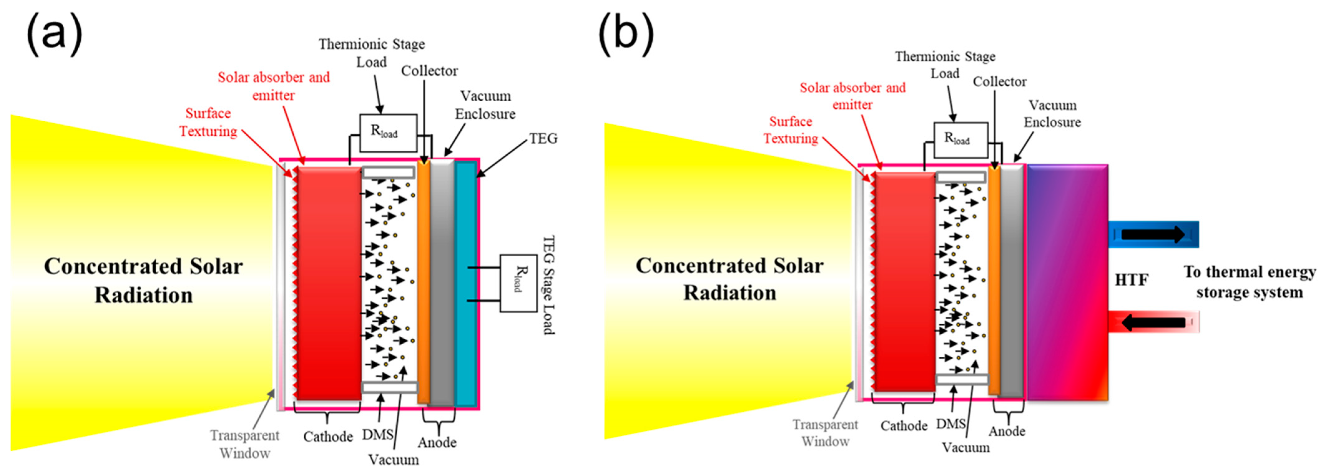
2.3. Hybridization of TEC with Secondary Conversion Stages
The advantage connected to the parallel-plate architecture of a TEC is in the matching of a secondary stage of conversion. The thermionic anode collects a thermal flux which can be converted. On the other hand, heat dissipation from the anode is vital to avoid overheating. As shown in the evaluation of the TEC performance, a lower anode temperature improves the conversion efficiency at the given thermionic properties of the electrodes (e.g., for Φ
C = 2.0, η = 25.9% and 25.4% at
TA = 500 °C and 600 °C, respectively). In this study, two different solutions for the secondary stage are analyzed (as shown in
Figure 5):
(1) The use of thermoelectric generators (TEG), that can exploit the exhaust heat producing instantaneous electrical power when a temperature difference is established between the two sides of the generator. In this case, TEGs will be mounted directly in contact with the bottom surface of the anode (i.e., the opposite face with respect to the TEC structure). An additional cold plate component and related cost must be considered for the TEG cooling so to maintain a suitable thermal gradient for maximizing the output power.
(2) The use of a thermal storage system, based on heat transfer fluid (HTF) technology (depending on operating temperatures), feeding on demand for example a Stirling engine, which can provide additional electricity when desired. In this case, the presence of a suitable tank is considered for the thermal exchange with the HTF sub-system, whereas conventional blocks for the thermal energy storage and the Stirling engine can be used.


