


Energy Efficiency Optimization of Collaborative Power Supply System with Supercapacitor Storages

 ,
,
Abstract
:1. Introduction
- (1)
- The system architecture and efficiency flow block diagram of the collaborative energy storage charging system is proposed;
- (2)
- Based on the main parameters of the on-board supercapacitor, the efficiency of the two charging forms is calculated and analyzed. It can be concluded that the energy storage synergy is feasible to improve energy efficiency;
- (3)
- Finally, the configuration scheme of the supercapacitor energy storage system is implemented and demonstrated in real operation.
2. Module Charging System Architecture
2.1. Topology of Power Supply System
- (1)
- The grid voltage of the distribution network is lowered; 10 kV or 0.4 kV power supply can be used for access.
- (2)
- Transformer capacity is reduced. During the operation period, the transformer is able to work under rated conditions, regardless of whether the vehicles are charged or not.
- (3)
- The supercapacitor-based energy storage system supplies power to vehicles when they enter the station, and vice versa.
- (4)
- During the load, power is flattened by energy storage; the boosted DC/DC can work stably under the rated operating conditions, regardless of whether vehicles are charging in the station.
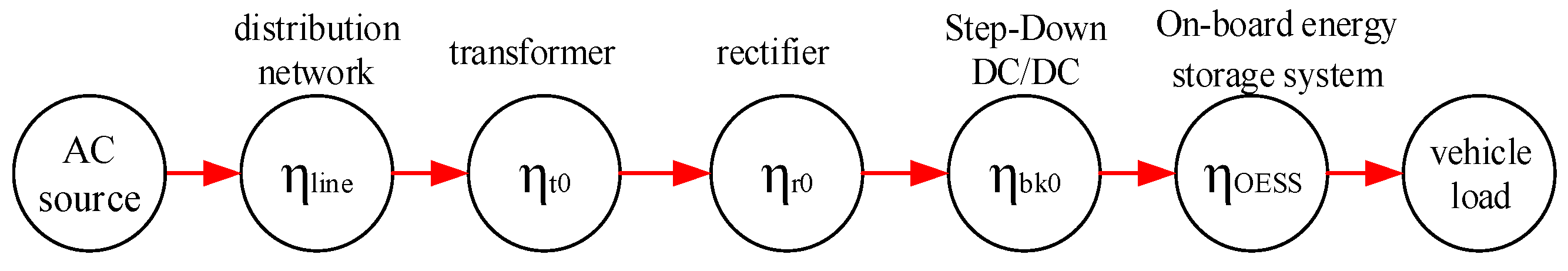
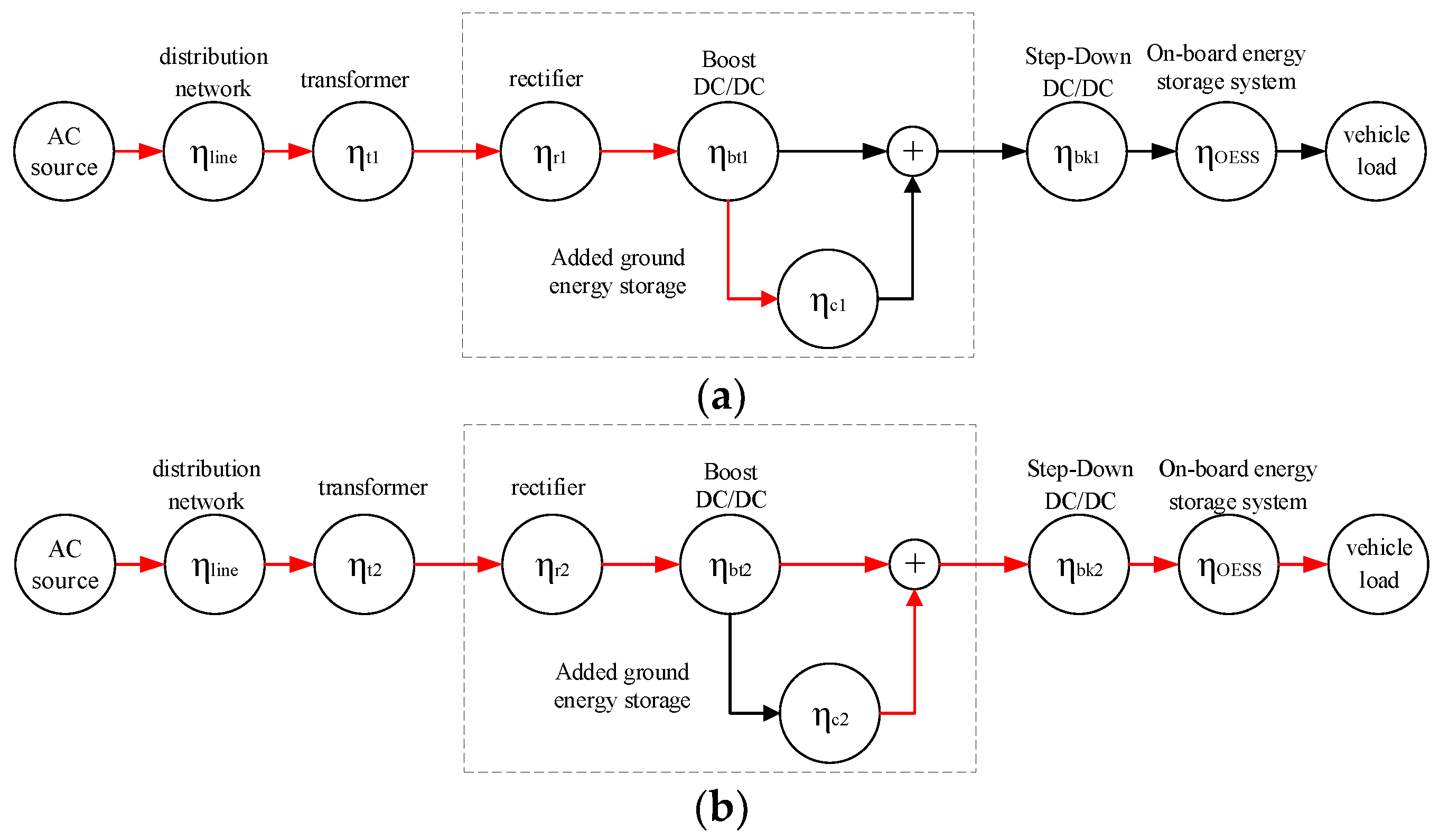
2.2. Efficiency Chain Model of the Charging System
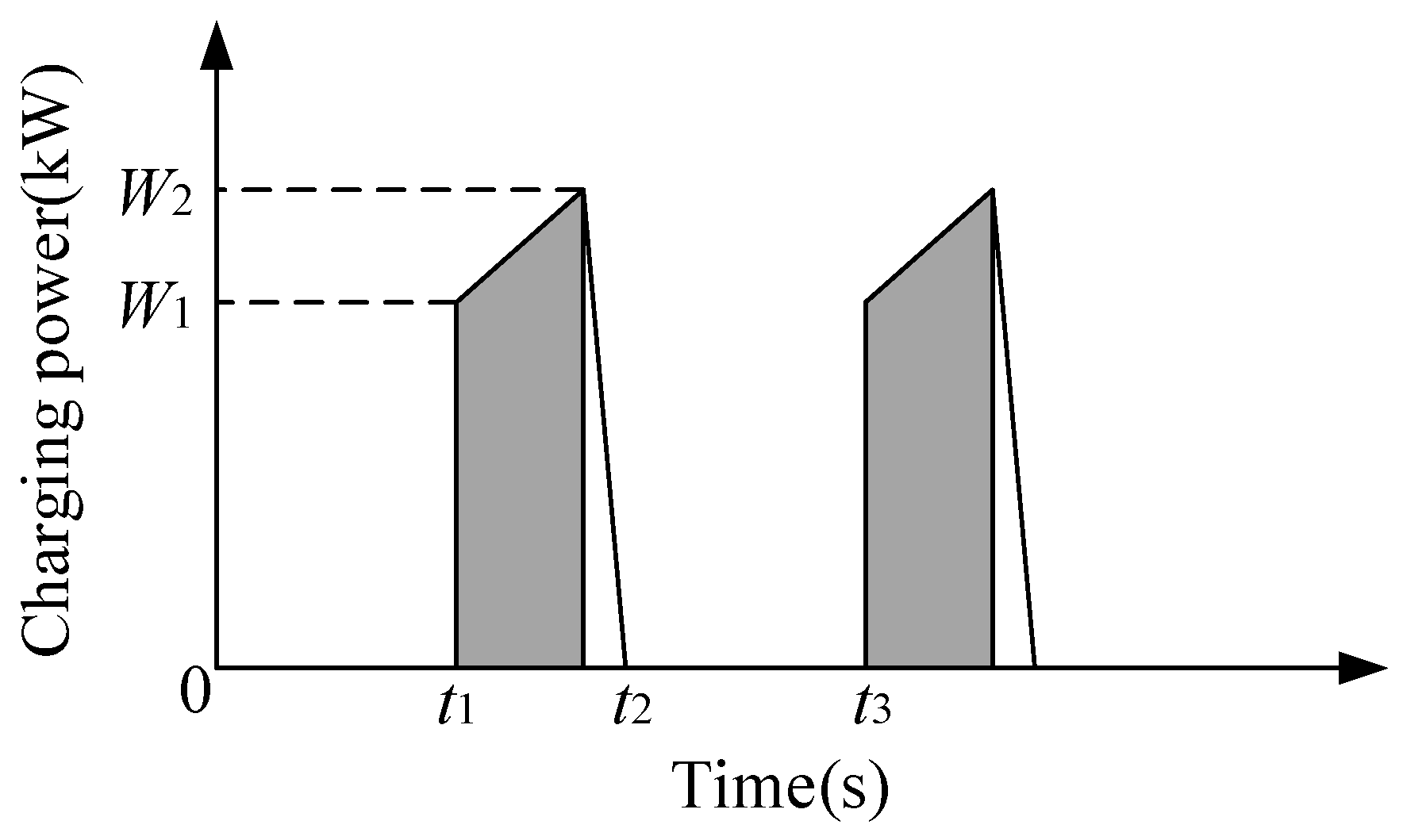
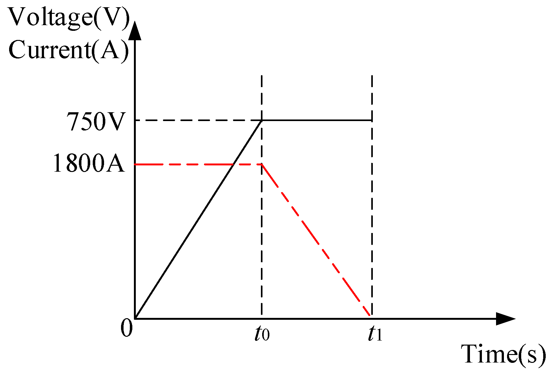
2.3. Load Characteristics Analysis of Charging System
3. Case Analysis
3.1. Calculation of Power System Efficiency
3.1.1. Direct Charging
3.1.2. Energy Storage Synergy
3.2. Design of Ground Energy Storage Device
3.2.1. Capacity Configuration
- (1)
- Charged to 3.45 V at 35 A and discharged at 110 A for 50 s, energy efficiency averaged 96.60%;
- (2)
- Charged to 3.45 V at 35 A and discharged at 140A for 50 s, energy efficiency averaged 96.20%;
- (3)
- Charged to 3.45 V at 35 A and discharged at 170 A for 50 s, energy efficiency averaged 95.50%;
- (4)
- Fully charged and fully discharged at 100 A, energy efficiency averaged 94.33%.
3.2.2. Circuit Configuration
3.2.3. Control Strategy
- (1)
- System current: the bus current sensed by the Hall sensor. The discharge direction of the system denotes a positive value, and the charging direction denotes a negative value.
- (2)
- System voltage: the total system voltage collected through the high-voltage sample line in the bus, different from the accumulated voltage obtained by monitoring the monomer. When the high-voltage sample line in a bus is recognized as invalid, the system will switch to show the accumulated voltage of the monomers and report the fault.
- (3)
- The highest voltage of a single cell: the highest parallel node voltage in the energy storage system, which determines the charging limit of the system.
- (4)
- The maximum temperature of the module: the highest temperature displayed by all temperature sensors of the energy storage system. When the temperature is too high, the system will alarm to prevent thermal failure.
3.3. Working Mode
- Step1:
- Read the voltage value (U) of the current power supply rail through the voltage sensor for status judgment;
- Step2:
- If U = 0, charge the energy storage device at a preset low power by a boost DC/DC converter; if U ≠ 0, check whether the disconnector of the current power supply system is closed;
- Step3:
- If the disconnector is closed, continue to perform step 2; if not, then close the disconnector of the power supply rail currently connected to the vehicle to be charged;
- Step4:
- Collect the electric energy from the boost DC/DC converter and the energy storage device through a step-down DC/DC converter and transfer the obtained energy to the vehicle;
- Step5:
- Check through the voltage sensor whether the current voltage at the supply rail reaches the full voltage;
- Step6:
- If yes, disconnect the disconnector at the power supply rail.
3.4. Energy Efficiency Analysis before and after Upgrade
4. Conclusions
- (1)
- The charging topology and main parameters of the collaborative energy storage system are designed, and the efficiency chain model and load characteristics of the charging system are analyzed. The power supply topology of the ground energy storage system is designed based on the supercapacitor and the boost DC/DC converter, which have good flexibility to realize the upgrade of the existing power supply system.
- (2)
- The proposed system effectively reduces the transformer capacity requirement, the no-load loss, and load loss. After adding supercapacitor energy storage, the transformer can charge the supercapacitor when the vehicle enters the station; after the vehicle enters the station, the transformer maintains the same charge power with the ground supercapacitor providing additional power.
- (3)
- Based on the system power flow transfer, the system efficiency expression is obtained, and the topology performance is theoretically analyzed. Calculation of energy consumption data demonstrates that the energy efficiency of the energy storage collaborative power supply system has been significantly improved by 5%.
- (4)
- The proposed topology can also reduce the exclusive requirements for front-end grid power supply, suitable for some areas without 10 kV dedicated lines or scenarios for new energy power supply. Meanwhile, it provides a reference for subsequent research, such as on canceling the rectifier and charging the energy storage system on the ground directly through AC/DC.
Author Contributions
Funding
Data Availability Statement
Conflicts of Interest
Nomenclature
| Dpeak | Number of departures per hour |
| Ech | Energy consumption of ground energy storage during each charging in case of coordinated power supply by supercapacitor |
| Eop | Charging quantity of on-board energy storage system of each pair of vehicles |
| Eloss,dd | Energy loss of step-down DC/DC during each charging in case of coordinated power supply by supercapacitor |
| Eloss,Tv | Energy loss of transformer during each charging in case of coordinated power supply by supercapacitor |
| Eloss,Rv | Energy loss of rectifier during each charging in case of coordinated power supply by supercapacitor |
| Eloss,ddv | Energy loss of boost DC/DC during each charging in case of coordinated power supply by supercapacitor |
| Eloss,sc | Energy loss of ground energy storage during each charging in case of coordinated power supply by supercapacitor |
| Eloss,ddc | Every time the ground energy storage system is replenished, the energy loss of the boost DC/DC |
| Eloss,Rc | Every time the ground energy storage system is replenished, the energy loss of the rectifier |
| Eloss,Tc | Every time the ground energy storage system is replenished, the energy loss of the transformer |
| Eloss,Tul | No-load loss of transformer |
| Eloss,dd,day | Total daily loss of step-down DC/DC |
| Eloss,sc,day | Total daily loss of ground energy storage system |
| Eloss,boost,day | Total daily loss of boost DC/DC |
| Eloss,R,day | Total daily loss of rectifier |
| Eloss,T,dayv | Total daily loss of transformer |
| Eloss,wd,sum | Total daily loss of summer working days |
| Eloss,wk,aut | Total daily loss of summer rest days |
| Eloss,wd,aut | Total daily loss of autumn working days |
| Eloss,wk,aut | Total daily loss of autumn rest days |
| Eloss,day | Total daily loss |
| Eop,sum | Charging energy consumption per pair in summer |
| Eop,aut | Charging energy consumption per pair in autumn |
| Nday | Total number of daily departures |
| Nwd | Daily total number of departure pairs on working days |
| Nwk | Daily total number of departure pairs on rest days |
| Pch | Rated power of charger |
| Trech | The charge time of a single cycle of the transformer |
| tcharge | Charging time |
| tinterval | Charging interval time |
| η | The supercapacitor energy efficiency of the collaborative energy storage power charging system |
| ηline | The distribution network efficiency |
| ηOESS | The on-board energy storage system efficiency |
| ηt0 | The transformer efficiency when the direct charging system during charging period |
| ηr0 | The rectifier efficiency when the direct charging system during charging period |
| ηbk0 | The step-down DC/DC efficiency when the direct charging system during charging period |
| ηt1 | The transformer efficiency when the collaborative energy storage charging system during idle period |
| ηr1 | The rectifier efficiency when the collaborative energy storage charging system during idle period |
| ηbt1 | The boost DC/DC efficiency when the collaborative energy storage charging system during idle period |
| ηc1 | The energy storage system charging efficiency when the collaborative energy storage charging system during idle period |
| ηbk1 | The step-down DC/DC efficiency when the collaborative energy storage charging system during idle period |
| ηt2 | The transformer efficiency when the collaborative energy storage charging system during charging period |
| ηr2 | The rectifier efficiency when the collaborative energy storage charging system during charging period |
| ηbt2 | The boost DC/DC efficiency when the collaborative energy storage charging system during charging period |
| ηc2 | The energy storage system discharge efficiency when the collaborative energy storage charging system during charging period |
| ηbk2 | The step-down DC/DC efficiency when the collaborative energy storage charging system during charging period |
| ηTch | Efficiency of a single cycle of the transformer |
| ηstop | Daily average power supply efficiency |
| ηsum,week | Average weekly power supply efficiency in summer |
| ηaut,week | Average weekly power supply efficiency in autumn |
References
- Yang, Y.; Chen, Z.J. Research and Development of Energy Storage Electric Traction Light Rail Transport. Electr. Locomot. Mass Transit Veh. 2012, 35, 5–10+20. [Google Scholar]
- Tian, W.; Chang, P.; Lin, C. Analysis of Tram Charging Device under Different Power Supply Networks. Mod. Urban Transit 2018, 8, 13–15. [Google Scholar]
- Radaš, I.; Župan, I.; Šunde, V.; Ban, Ž. Route Profile Dependent Tram Regenerative Braking Algorithm with Reduced Impact on the Supply Network. Energies 2021, 14, 2411–2432. [Google Scholar] [CrossRef]
- He, Z.; Zhao, Y.; Zhu, D.; Su, X. Research on the Charging Device of Energy-storage Tram for Parking-lot. Electr. Drive 2018, 48, 70–74. [Google Scholar]
- Zhang, G.; Li, Q.; Chen, W.; Meng, X.; Deng, H. A coupled power-voltage equilibrium strategy based on droop control for fuel cell/battery/supercapacitor hybrid tramway. Int. J. Hydrog. Energy 2019, 44, 19370–19383. [Google Scholar] [CrossRef]
- Yang, J.; Xu, X.; Peng, Y.; Zhang, J.; Song, P. Modeling and optimal energy management strategy for a catenary-battery-ultracapacitor based hybrid tramway. Energy 2019, 183, 1123–1135. [Google Scholar] [CrossRef]
- Wei, S.; Murgovski, N.; Jiang, J.; Hu, X.; Zhang, W.; Zhang, C. Stochastic optimization of a stationary energy storage system for a catenary-free tramline. Appl. Energy 2020, 280, 115711. [Google Scholar] [CrossRef]
- Oukkacha, I.; Sarr, C.T.; Camara, M.B.; Dakyo, B.; Parédé, J.Y. Energetic Performances Booster for Electric Vehicle Applications Using Transient Power Control and Supercapacitors-Batteries/Fuel Cell. Energies 2021, 14, 2251–2272. [Google Scholar] [CrossRef]
- Wei, S.; Jiang, J.; Cheng, L. Optimal Sizing Model of the Energy Storage Type Tramway Considering the Integration of on-Board Energy Storage and off-Board Energy Supply. Trans. China Electrotech. Soc. 2019, 34, 229–238. [Google Scholar]
- Wang, B.; Yang, Z.; Lin, F.; Zhao, W. Study on Optimization of Capacity Configuration of Stationary Super Capacitor Storage System for Improving Energy Efficiency and Voltage Profile. J. China Railw. Soc. 2016, 38, 45–52. [Google Scholar]
- Su, X.; Zhu, L.; Tian, W. Research on Control for Tram Charging Device Based on Super-capacitor. Power Electron. 2016, 50, 60–62. [Google Scholar]
- Di Noia, L.P.; Genduso, F.; Miceli, R.; Rizzo, R. Optimal integration of hybrid supercapacitor and IPT system for a free-catenary tramway. IEEE Trans. Ind. Appl. 2018, 55, 794–801. [Google Scholar] [CrossRef]
- Li, H.; Peng, J.; He, J.; Zhou, R.; Huang, Z.; Pan, J. A cooperative charging protocol for onboard supercapacitors of catenary-free trams. IEEE Trans. Control Syst. Technol. 2017, 26, 1219–1232. [Google Scholar] [CrossRef]
- Şahin, M.E.; Blaabjerg, F.; Sangwongwanich, A. A comprehensive review on supercapacitor applications and developments. Energies 2022, 15, 674–699. [Google Scholar] [CrossRef]
- Guo, C.; Zhang, A.; Zhang, H. Model Predictive Control for Tram Charging and its Semi-physical Experimental Platform Design. J. Power Electron. 2018, 18, 1771–1779. [Google Scholar]
- Herrera, V.; Milo, A.; Gaztañaga, H.; Etxeberria-Otadui, I.; Villarreal, I.; Camblong, H. Adaptive energy management strategy and optimal sizing applied on a battery-supercapacitor based tramway. Appl. Energy 2016, 169, 831–845. [Google Scholar] [CrossRef]
- Chang, P.; Tian, W.; Lin, C. Research on Energy Storage Type Charging Devices for Modern Trams. Electr. Autom. 2019, 41, 102–104. [Google Scholar]
- Xie, Y.; Bai, Y. Overall Capacity Allocation of Energy Storage Tram with Ground Charging Piles. Energy Storage Sci. Technol. 2021, 10, 1388–1399. [Google Scholar]
- Wu, W.; Hu, J.; Yang, H.; Feng, A. Research on a 2 MW Timcar Charqlng Device. Electr. Veh. Technol. 2020, 42, 47–49+101. [Google Scholar]
- Rong, L.; Tian, W.; Sun, Z. Research on Charging Device of Super Capacitor Tram. Power Electron. 2020, 54, 11–14. [Google Scholar]
- Zahng, W.; Tao, Z.; Luo, Q.; Zheng, R. Development of an Isolated Charing Device for Energy-storage Trams. Power Electron. 2021, 55, 34–36+48. [Google Scholar]
- Jin, X.; Chen, Y. Study on Optimization Design of Fast Energy Storage in the Charging Device of the Tram. Comput. Simul. 2017, 34, 151–155+225. [Google Scholar]
- Yang, J.B.; Xu, X.H.; Peng, Y.Q. Optimal Parameter Matching of Hybrid Energy Storage System Based on NSGA-Ⅱ Algorithm for Energy Storage Type Tram. J. Mech. Eng. 2020, 56, 181–189. [Google Scholar]
- Ciccarelli, F.; Iannuzzi, D.; Kondo, K.; Fratelli, L. Line-voltage control based on wayside energy storage systems for tramway networks. IEEE Trans. Power Electron. 2015, 31, 884–899. [Google Scholar] [CrossRef]
- Zhou, Y.; Zhang, L.; Xiu, S.; Hao, W. Design and Analysis of Platform Shielding for Wireless Charging Tram. IEEE Access 2019, 7, 129443–129451. [Google Scholar] [CrossRef]
- Yan, Y.; Li, Q.; Chen, W.; Su, B.; Liu, J.; Ma, L. Optimal energy management and control in multimode equivalent energy consumption of fuel cell/supercapacitor of hybrid electric tram. IEEE Trans. Ind. Electron. 2018, 66, 6065–6076. [Google Scholar] [CrossRef]
- Qiu, L.; Wang, X.; Tao, Z. Analysis and Protection of Output Over-voltage for Energy Storage Tram Charging Device. Urban Mass Transit 2020, 23, 72–74. [Google Scholar]
- Yang, L.; Wei, S. Improvement of Ground Power Supply Scheme for Energy Storage Tram. Electr. Locomot. Mass Transit Veh. 2020, 43, 56–60+64. [Google Scholar]
- Zhang, W.; Wen, W. Ground Charging System for Energy Storage Modern Tram. Electr. Locomot. Mass Transit Veh. 2015, 38, 30–32. [Google Scholar]
- Chen, W.; Shi, F.; Dai, C.; An, Q.; Liu, Y.; Liu, Y. Energy Management Strategy of Hybrid Tram Based on Dynamic Degree of Hybrid. J. Southwest Jiaotong Univ. 2020, 55, 409–416. [Google Scholar]


| Parameter | Value |
|---|---|
| Vehicle marshaling (Car) | 4 |
| Capacity (F) | 130 |
| Rated voltage (V) | 750 |
| Voltage range (V) | 500~900 |
| Charging current (A) | 1800 |
| Current collection mode | Station stationary charging |
| Device | Parameter |
|---|---|
| Input voltage | Three-phase AC 10 kV (−15~+7%) |
| Input voltage harmonics | ≤3% (31 times or less) |
| Input power factor | Specified load ≥ 0.95, No load ≥ 0.90 |
| Transformer rated power | 125 kVA |
| Charging method | Constant current, limited voltage, and constant power |
| Output charging voltage | 500~900 V |
| Output power | Total output power ≤ 700 kW and the current can be adjusted according to the operating conditions |
| Working form | Continuous uninterrupted work |
| Season | Summer | Autumn |
|---|---|---|
| Traction energy consumption (kWh) | 3.0 | 3.0 |
| Auxiliary energy consumption (kWh) | 3.0 | 2.0 |
| Charging energy consumption (kWh) | 6.0 | 5.0 |
| Season | Workday | Rest Day | ||
|---|---|---|---|---|
| Sum. | Fal. | Sum. | Fal. | |
| DC/DC daily loss (kWh) | 7.31 | 4.26 | 8.13 | 4.74 |
| Rectifier daily loss (kWh) | 4.92 | 2.87 | 5.48 | 3.19 |
| Transformer daily loss (kWh) | 48.21 | 46.89 | 48.56 | 47.10 |
| Total daily loss (kWh) | 60.44 | 54.03 | 62.17 | 55.04 |
| Average daily power supply efficiency (%) | 88.82 | 83.83 | 89.57 | 84.98 |
| Parameter | Value |
|---|---|
| Full load power of transformer (kW) | 125 |
| No-load loss power of transformer (kW) | 0.14 |
| Load loss power of transformer (kW) | 1.53 |
| Step-down DC/DC charging efficiency | 0.985 |
| Transformer load efficiency | 0.9868 |
| Full load efficiency of rectifier | 0.99 |
| Boost DC/DC efficiency | 0.992 |
| Average Power Supply Efficiency | Original Power Supply System (%) | Energy Storage Power Supply System (%) | Growth Rate (%) |
|---|---|---|---|
| Summer | 89.05 | 92.98 | 4.41 |
| Autumn | 83.22 | 87.92 | 5.65 |
| Daily | 86.14 | 90.45 | 5.00 |
| Parallel Connection | Series Connection | Voltage (V) | Monomer Charge–Discharge Current (A) | Monomer Discharge Energy (Wh) | Voltage Test |
|---|---|---|---|---|---|
| 2 | 408 | 1400 | <55.140 | 10.42 (3.185~3.45 V) | Satisfied |
| 384 | 1300 | <55.151 | 11.07 (3.180~3.45 V) | Satisfied | |
| 348 | 1200 | <55.163 | 12.22 (2.816~3.45 V) | Not satisfied | |
| 324 | 1100 | 55.178 | 13.12 (2.764~3.45 V) | Not satisfied | |
| 3 | 408 | 1400 | <35.93 | 6.95 (3.214~3.45 V) | Satisfied |
| 384 | 1300 | <35.100 | 7.38 (3.211~3.45 V) | Satisfied | |
| 348 | 1200 | <35.108 | 8.15 (3.205~3.45 V) | Satisfied | |
| 324 | 1100 | 35.118 | 8.75 (3.199~3.45 V) | Satisfied |
| Parameter | Value |
|---|---|
| Monomer | 3.6 V/60,000 F |
| Total system power (kWh) | 52.2 |
| Rated voltage (VDC) | 1252.8 |
| Optimal working voltage (VDC) | 835.3~1218 |
| Standard charge–discharge current (A) | 300 |
| Pulse current@30 s (A) | 900 |
| Electricity Consumption (6 Months) | Before | After |
|---|---|---|
| AC (kWh) | 85,200 | 77,910 |
| DC (kWh) | 73,633 | 71,429 |
| Average AC/DC conversion rate (%) | 86.42 | 91.68 |
Disclaimer/Publisher’s Note: The statements, opinions and data contained in all publications are solely those of the individual author(s) and contributor(s) and not of MDPI and/or the editor(s). MDPI and/or the editor(s) disclaim responsibility for any injury to people or property resulting from any ideas, methods, instructions or products referred to in the content. |
© 2023 by the authors. Licensee MDPI, Basel, Switzerland. This article is an open access article distributed under the terms and conditions of the Creative Commons Attribution (CC BY) license (https://creativecommons.org/licenses/by/4.0/).
Share and Cite
Deng, Y.; Li, C.; Deng, Y.; Chen, T.; Feng, S.; Chu, Y.; Li, C. Energy Efficiency Optimization of Collaborative Power Supply System with Supercapacitor Storages. Energies 2023, 16, 1227. https://doi.org/10.3390/en16031227
Deng Y, Li C, Deng Y, Chen T, Feng S, Chu Y, Li C. Energy Efficiency Optimization of Collaborative Power Supply System with Supercapacitor Storages. Energies. 2023; 16(3):1227. https://doi.org/10.3390/en16031227
Chicago/Turabian StyleDeng, Yibo, Chushan Li, Yan Deng, Ting Chen, Shaoyu Feng, Yujie Chu, and Chengmin Li. 2023. "Energy Efficiency Optimization of Collaborative Power Supply System with Supercapacitor Storages" Energies 16, no. 3: 1227. https://doi.org/10.3390/en16031227
APA StyleDeng, Y., Li, C., Deng, Y., Chen, T., Feng, S., Chu, Y., & Li, C. (2023). Energy Efficiency Optimization of Collaborative Power Supply System with Supercapacitor Storages. Energies, 16(3), 1227. https://doi.org/10.3390/en16031227