Article

Experimental Study on Active Thermal Protection for Electronic Devices Used in Deep−Downhole−Environment Exploration

1
Key Laboratory of Thermo−Fluid Science and Engineering, MOE, School of Energy and Power Engineering, Xi’an Jiaotong University, Xi’an 710049, China
2
Xi’an Shanguang Energy Co., Ltd., Xi’an 710075, China
3
State Key Laboratory of Electrical Insulation and Power Equipment, Xi’an Jiaotong University, Xi’an 710049, China
*
Author to whom correspondence should be addressed.
Energies 2023, 16(3), 1231; https://doi.org/10.3390/en16031231
Submission received: 16 December 2022 / Revised: 11 January 2023 / Accepted: 20 January 2023 / Published: 23 January 2023

Abstract

:
Electronic devices are commonly used for exploiting and extracting shale oil in deep downhole environments. However, high−temperature−and−pressure downhole environments jeopardize the safe operation of electronic components due to their severe thermal conditions. In the present study, an active thermal−insulation system is proposed, which consists of a spiral annular cooling plate (ACP), a thermal storage container with phase−change material (PCM) and an aerogel mat (AM). The effect of the ACP’s structure, layout and working−medium flowrate on the heat−protection performance were experimentally measured; temperature−control capability and system−operating time were used as the criteria. The results show that the AM layer is necessary and that the inner−ACP case displays better thermal−protection performance. Next, a dimensionless temperature−control factor (TCF) was proposed to evaluate the trade−off between temperature control and the system’s operating time. Note that the TCF of the spiral ACP can be improved by 1.62 times compared to the spiral−ACP case. Since the lower flowrate allows better TCF and longer operating times, intermittent control of the flowrate with a 1−minute startup and 2−minute stopping time at 200 mL/min can further extend the system’s operating time to 5 h, and the TCF is 3.3 times higher than with a constant flowrate of vm = 200 mL/min.

1. Introduction

Fossil energy is the most important resource in industrial production and dominates the world’s energy economy. In recent decades, the exploration and industrial development of shale−oil commercial production have stimulated the international crude−oil market. According to published data, there are approximately 400 billion tons of shale oil in the world, which is higher than the verified exploitable reserves of conventional crude oil by almost 100 billion tons [1].
For shale−oil extraction, the direct application of conventional hydraulic piezolization technology is vulnerable and shows low permeability and efficiency due to the complex geology involved [2]. In this regard, novel perforation technologies, such as the shock waves produced by electric exploding metallic wires, are usually applied. These can effectively generate dense fissures, increase the fissure density and pore size of the reservoir and, thus, improve the permeability of the working medium in shale−oil reservoirs. It is known that the ambient temperature and absolute pressure in a 2−kilometer−deep well can reach 120 °C and 20 MPa, respectively [3]. High−temperature−resistance devices and electronics are applied, since the material technology has developed rapidly in recent years. However, equipment failures still commonly occur because of the temperature−related safety operation of electronics [4]. Furthermore, the high cost of high−temperature devices restricts their commercial application. Thus, effective thermal−protection measures are always implemented; they are regarded as more effective, economical, and reliable technologies, ensuring the safe and stable operation of electronic equipment in high−temperature downhole environments.
These thermal−protection technologies can be divided into the passive type and the active type, based on the assembly of the driven component. The passive thermal−protection strategy usually introduces low−conductivity materials, such as asbestos, diatomite, aerogel, organic foams, aerogels, and composites [5,6,7]. Meanwhile, vacuum measures (Dewar flask) with extremely high thermal resistance and phase−change materials (PCMs) with high latent heat storage also feature strong thermal−insulation characteristics [8], which have been extensively investigated by many scholars.
Ma et al. [9] proposed a thermal−management method based on a combination of vacuum insulation and PCM, capable of reducing the temperature of electronic components to below 120 °C within 6 h at an ambient temperature of 200 °C. Rafie et al. [10] proposed a new system of nano−porous insulating materials that is superior to and more economical than conventional designs. Zhang et al. [11] combined the finite−element method with the Nelder–Mead algorithm to optimize the thermal design of the logging tool. The maximum temperature of the heat source was reduced from 163.1 °C to 123 °C and the heat stored in the PCM was increased by 13.7%. He et al. [12] proposed a downhole thermal−management system using different materials for the thermal protection of electronics. The results showed that glass wool and phenolic resin can extend the safe working time by 57% at 100 °C, while aerogel was more effective. Lan et al. [13] proposed a distributed thermal−management system (DTMS) with a PCM dispersed in the skeleton. Compared to conventional thermal−protection systems, the DTMS has a maximum temperature reduction of 68 °C and 3.5 times the heat storage capacity of the PCM. Shang et al. [14] described a passive thermal−protection system for downhole electronic equipment consisting of a vacuum flask, PCM, and heat pipes. The results showed that the system can maintain equipment temperatures below 125 °C for 6 h at 200 °C. It should be noted that the passive methods can only provide short periods of cooling due to the constant temperature boundary in external downhole environments. The insulation effect might be gradually eliminated and completely invalid, with heat continuously transferring through the outside environment. Meanwhile, the thermal−insulation capacity of passive thermal methods might gradually decrease as the ambient temperature rises. Hence, active cooling methods are proposed. These are capable of effectively removing incoming heat. A suitable thermodynamic cycle might be introduced, and higher heat−removal efficiency, longer operating times and the greater safety reliability of electronics can be achieved.
Compression−cooling technology is commonly used as an active thermal−protection method. Bennett [15] summarized seven design approaches and guidelines for active thermal−protection techniques for downhole instrumentation, including the reverse Brayton cycle and the Stirling cycle, which offer feasibility based on viability, which is of great relevance to downhole−thermal−protection research. Flore [16] designed and manufactured a disposable mechanical vapor−compression cooler with water as the refrigerant. The temperatures were maintained at 125 °C for extended periods in a well environment at 200 °C. Gao et al. [17] developed a multi−stage Stirling chiller for downhole electronics to meet high cooling−capacity requirements. The results showed that the system consumes approximately 24 W to maintain the circuit compartment at 90 °C when applied in wells at 150 °C. On the other hand, a thermoelectric module was also introduced as an active cooling device. Soprani et al. [18] presented a method to optimize thermoelectric−module systems, which made it possible to maintain devices at temperatures more than 33 K below the well temperature. Weerasinghe et al. [19] predicted the performance of thermoelectric modules and then proposed a customized module for downhole tools maintained the internal temperature at 30 °C, which was lower than the external ambient temperature of 160 °C. Sinha et al. [20] introduced a thermoelectric unit with a heat exchanger and cold plate to remove heat from an electronic module. The system is able to keep the chip 35–38 °C cooler than the surrounding temperature at 0~8 W of heat dissipation, at an ambient temperature of 140 °C.
Other forms of thermal protection in underground environments are also available. Holbein et al. [21,22] suggested that downhole coolers are a promising approach to the provision of strong support for downhole operations and designed the concept of an integrated cooling system. Bennett [23] investigated an acoustic−cooled active thermal−protection system for cooling downhole electronics in geothermal logging tools. The thermoacoustic cooler was used to remove heat from the insulation chamber and the hot end was deployed for the final heat removal. Alrumaidh et al. [24] introduced the throttling effect of nitrogen to prevent logging tools from breaking down due to high temperatures and showed that the drilling fluid was reduced by 22.4 °C in the area where the tool was located. Some scholars have also proposed the joint application of active and passive thermal protection in the field of underground thermal protection. Verma et al. [25] created a new thermal−protection system by combining vacuum−jacketed housing and a vapor−compression cycle and proposed a method of analysis to determine the fluid. Their experimental results showed that the tool could safely operate at 250 °C when adjusting the refrigerant flowrate at 10 mL/min. Jakaboski [26] designed an active thermal−protection system for logging electronics combined with the use of phase−change material as a temporary thermal−storage device. The cooling load can be rapidly alleviated at harsh ambient temperatures. It should be noted that the combined application of active and passive thermal protection has now emerged more widely in a number of research areas, such as batteries [27,28], the thermal protection of engines [29,30], and aircraft insulation [31,32].
Figure 1 depicts the insulation mechanisms with both passive and active technologies. As mentioned above, the passive strategy can only maintain the temperature of the inner environment for a short period due to the constant temperature−boundary conditions in these environments. On the other hand, the active strategy shows a stronger prominent performance because of the persistent heat−removal process. In the present paper, the development of an active thermal−insulation system (ATIS) with long and thin features is reported. An annular cooling plate (ACP) combined with a thermal storage container were applied to the thermal protection of a motor and lithium batteries used in a high−temperature downhole environment. The effects of the flowrates and pump−running modes, as well as the hybrid layout of the ATIS, were experimentally investigated in comparison to a passive thermal−insulation strategy. Meanwhile, the trade−off between the controlled temperature and the system’s operating time was also analyzed. Eventually, an innovative spiral−type annular cooling plate was proposed. The plate offers pronounced improvement in thermal−insulation efficiency without a flow dead zone. The corresponding evaluation criteria were also proposed for the comprehensive performance comparison.

2. Experimental Setup

Figure 2a,b presents the schematic diagram and actual structure of the experimental systems, respectively. The ACP was arranged in the simulated downhole thermal environment, in which a constant high temperature was provided by an oil−bath vessel filled with dimethyl silicone oil. Two electric heating rods with a power of 2 kW were used in the oil−bath vessel and an electric stirrer was used continuously to ensure the uniformity of internal temperature.
Liquid water at a constant pressure liquid was applied as working medium in present study, and a variable−frequency peristaltic water pump was used, with a flowrate ranging from 50 to 470 mL/min. The pump might drive the working medium into the annular cooling plate. Next, after it was heated by the wall of simulated well, the working fluid was pumped into the PCM thermal storage container, where the heat was released. A glass−float flow meter was arranged for real−time monitoring of the flowrate; therefore, the system constituted a water−cooling cycle from the loop of pump, passing through the flowmeter, PCM container, and water−cooling plate before returning to the pump. The components were connected to each other by high−temperature−resistant silicone tubes and wrapped in rubber sleeves to prevent heat dissipation.
Figure 3 shows the schematic structure of the spiral−type ACP. The spiral annular cooling plate was fabricated by the three−dimensional−additive−material production process and composed of polylactic acid (PLA) material. Both the outer and inner shells were designed with cylindrical structures concentrically; therefore, the flow channels are separated into spiral types with the same shape and cross−sectional area. The inlets and outlets are arranged on the same side to coordinate the cooling−water circuits, and a total of six connections were designed with three couples of spiral structures. On the other side of annular cooling plate, the cladding channels are placed; therefore, the protected components can be coated perfectly and the working medium can flow without dead zones. The overall length of the annular cooling plate is 225.5 mm, with an external diameter of 89 mm and an internal diameter of 77 mm, based on the dimensions in the objectives.
The height and the external diameter of the thermal storage container are 0.15 m and 78 mm, respectively. The PCM in the thermal storage container was paraffin 60. A differential scanning calorimeter (DSC250) was used to measure the phase−change interval, latent heat, and specific heat. The sample was heated from 20 °C to 75 °C at a rate of 5 °C/min, and the results are shown in Figure 4 [33]. The temperature range of 54.7 °C to 59.4 °C was regarded as the phase−change region [34]. The latent heat and specific heat of paraffin were measured as 171.9 J/g and 2.46 kJ/(kg·K), respectively; therefore, the total latent heat−storage reached 118.1 kJ. A copper tube with a length of 0.49 m is used as the water−flow channel. In addition, the heating tape is used to mimic the high−temperature environment in which the container located. The aerogel is wrapped at the outer wall to ensure inward heat−flow direction and the thermocouples are used as sensors to provide constant−wall−temperature conditions.
The temperature was measured by a T−type thermocouple (Omega) with an accuracy of 0.1 °C. The thermocouples were connected to a 40−channel data−acquisition system (Yokogawa GM90PS, Japan). The temperature of oil bath, wall temperature of simulated well, the temperature at the inner wall of the annular cooling plate, and the inlet and outlet temperatures of working media of both ACP and PCM containers were measured, respectively. The external walls of the ACP and PCM containers maintained a constant temperature of 100 °C. The safe operating time of the system was set from the time the external temperature reached 100 °C to the time the lithium battery reached its critical temperature, at 70 °C. The proposed thermal−protection system should accomplish two tasks. One is that the temperature at the inner wall should be kept lower than the critical temperature of the lithium battery, which requires a high water flowrate to quickly remove heat from the ACP. The other is to extend the protection time with the fixed PCM container, which requires a low water flowrate to eliminate heat transfer in the PCM container. In this regard, the optimized flowrate requires a consideration of the trade−off between the protection of safety and time. For thermal protection in downhole environments, the critical factors in improving thermal−protection effects such as layouts, flow manner, and flowrate control are investigated.

3. Data Reduction

3.1. Evaluation of Thermal Performance

The heat flux transferred from the ACP to the PCM container can be calculated by the energy−conservation equation via q = v m c p ( T o T i ) . The inlet and outlet temperatures (Ti and To) and the mass flowrate were measured by T−type thermocouples and the flowmeter, respectively. The overall operating time of the thermal−protection system strongly depends on the size of the heat−storage container, as well as the charging rate. When applying a fixed PCM container, a lower charging rate is preferred to ensure the safe operation of devices. In other words, the inner−wall temperature can be maintained at its upper limit, but cannot exceed the critical temperature. As a result, the dimensionless temperature−control factor (TCF) is defined as
T C F = 1 n   T T s t T c r T s t · Δ t Δ T n
where T is the inner−wall temperature, Tcr is the critical temperature (fixed at 70 °C in the studied cases), Tst is the starting record temperature when the inner−wall temperature of the ACP at 30 °C, ∆T is the temperature variation, and n is the number of time steps for the monitored average temperatures in the inner walls.
The temperature−difference ratio, δ, is defined as follows:
δ = T T s t T c r T s t
The temperature−variation rate (TVR) can be calculated by Equation (4);
T V R = Δ t Δ T
The temperature coefficient shows how much heat flows into the water−cooled plate. However, excessive heat inflow can also lead to an excessive temperature coefficient when the effect of heat storage is less effective. For this reason, a phase−change coefficient was introduced to represent the effect of the heat−storage container. When both are large, good temperature control is obtained.

3.2. Experimental Uncertainty

Based on the uncertainty of the sensor measurements, the uncertainty of the other variables can be calculated using Equation (4) [35,36]:
α M = [ i = 1 n ( M x i α x i ) 2 ] 1 / 2
where M represents the variables and that of the function with the independent parameters. The αxi and the αM are the errors for each parameter and variable.

4. Results and Discussion

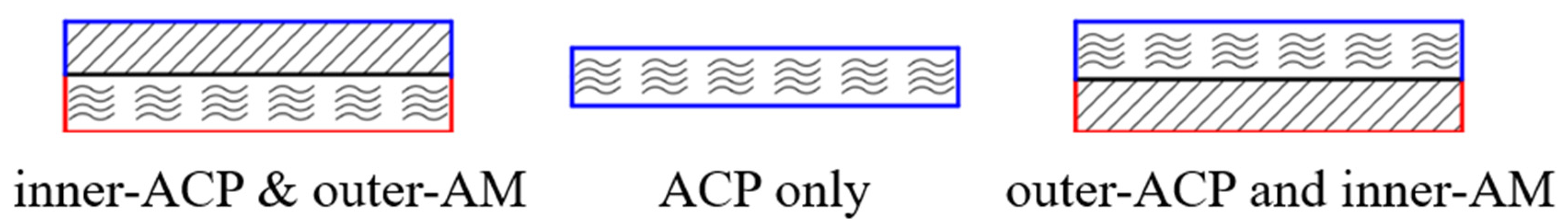
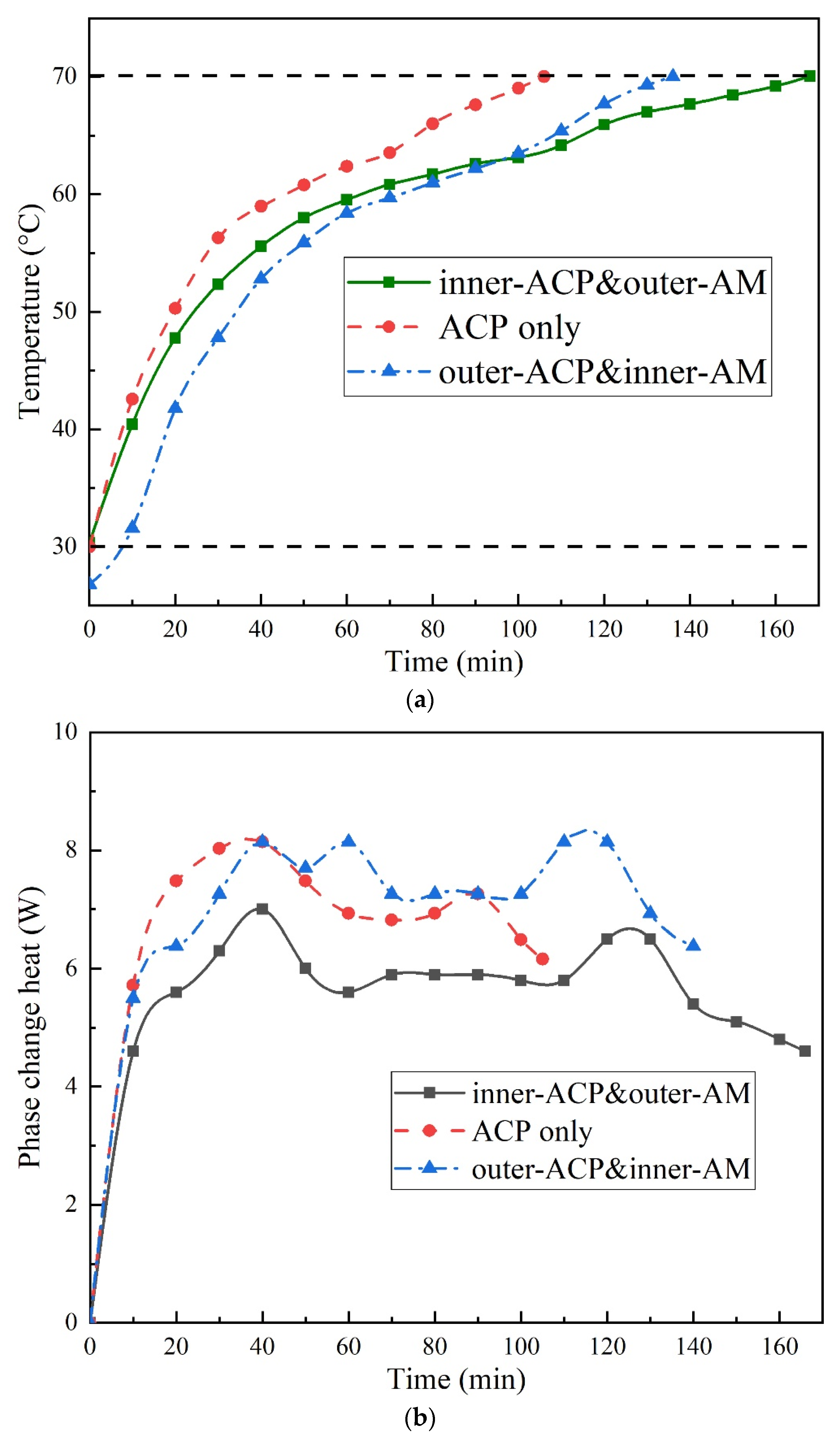
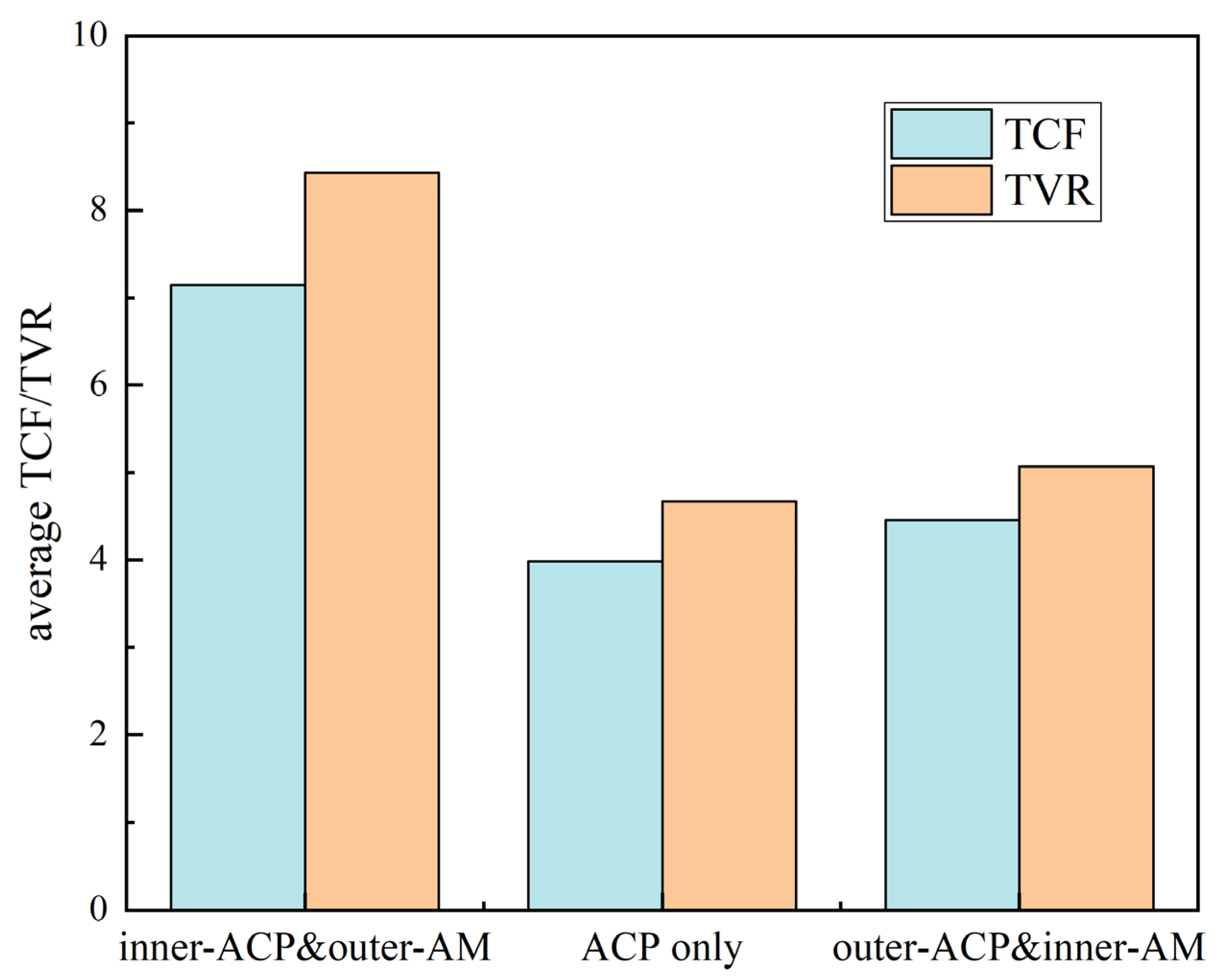
4.1. Comparison of Different Layouts

As mentioned above, hybrid strategies involving passive and active cooling are usually adopted. However, few studies investigate the effect of the layout on the thermal−protection performance, which is discussed in the present paper. The aerogel mat (AM) was applied as the insulation material, and Figure 5 shows the three investigated layouts: inner−ACP and outer−AM, ACP only, and outer−ACP and inner−AM.
Figure 6a shows the temperature changes in the inner wall over time. The flowrate of the thermal−protection system and the temperature of the simulated downhole environment are fixed at 100 mL/min and 100 °C, respectively. Note that the inner−wall temperatures of all three cases rose rapidly at the beginning, and gradually became smooth when the PCM container began to work. However, the increment gradient of the temperature rose rapidly again with the PCM capacity failing, and eventually reached the critical temperature. It can be inferred that the temperature of the case with ACP only might quickly reach critical levels, with the shortest operating time.
On the other hand, the two cases involving both the ACP and the AM showed much longer operating times, which were 32 min and 62 min longer than the case with the ACP only, respectively. Initially, the room temperature was fixed at 25 °C before testing. Compared to the inner−ACP case, the temperature change in the outer−ACP case was delayed at the beginning. This was because the operating time was counted when the temperature of the water in the ACP reached 30 °C. Due to the thermal resistance of the aerogel−insulation layer in the outer−ACP case, its temperature in the inner wall was lower than 30 °C. However, the temperature of the inner wall of the internal insulation gradually approached and eventually exceeded the temperature of the inner−ACP case at 96 min, suggesting a shorter operating time. The temperature−rise rate of the outer−ACP case was faster than that of the inner−ACP case, showing a similar trend to that of the ACP−only case. This can be explained by the fact that the heat−removal rate was much quicker for the outer−ACP case due to the strong convective−heat transfer between the ACP and the ambient, resulting in lower temperatures. When the PCM container was close to saturated, the temperature was liable to rise rapidly and even exceed the level of the inner−ACP case. Furthermore, the inner−ACP case provided an additional layer of thermal resistance and reduced the thermal load on the ACP, showing lower driven force (the temperature difference between the fluid and the wall). This can is verified in Figure 6b, which indicates the PCM’s heat −absorption rate, calculated by the energy−conservation equation. The heat−absorption trend for all three cases shows two peaks, correspondingly revealing the three stages, pre−phase change, in−phase change, and post−phase change, of the PCMs. The heat−absorption rate rose dramatically in the first 40 min due to the good heat transfer between the PCM and the copper tubes. However, due to the low conductivity of paraffin, the heat transfer was jeopardized and the heat−absorption rate started to decrease gradually. The inner−ACP case demonstrated the lowest heat−absorption rate; it therefore involved a longer operating time. On the other hand, the case with the outer ACP absorbed almost 20% more heat than that of the inner−ACP case most of the time and had a shorter operating time.
Figure 7 shows the average values of the TCF and TVR during the operating time. Generally, the TCF and TVR reflected the temperature−control capability of the thermal−management system and the effect of the PCM container, respectively. Note that differences between the ACP case and the outer−ACP case were rare. However, the TVR of the inner−ACP case was nearly twice as high as that of the other two cases. It was found that the outer−ACP case mainly relied on passive insulation rather than active temperature control, which was observed with the inner−ACP case. Considering the operating time, the TCF and TVR of the inner−ACP case were still much larger than those of the outer−ACP case.
It was also observed that the inner−ACP case effectively controlled the heat−flux transfer into the cooling plate; therefore, the working time of the PCM was extended effectively. On the other hand, the smaller difference in TCF between the inner−ACP case and other two cases indicates that the critical temperature was considered simultaneously.

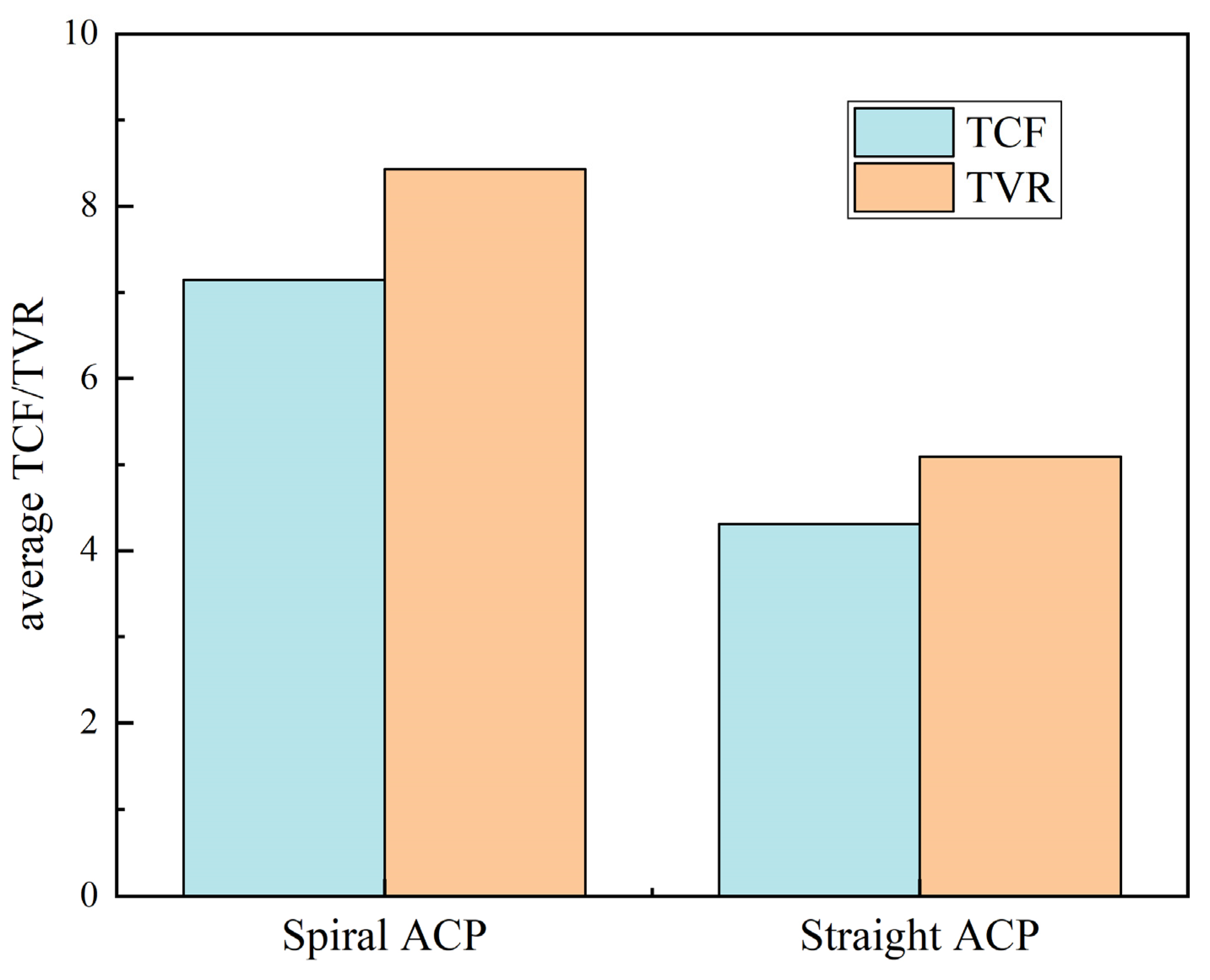
4.2. Development of Spiral ACP

It was verified that the inner−ACP case showed a stronger thermal−insulation performance. The water−cooled plate enables the cooling water to convey heat from the device to the PCM container along the flow path. The structure of the water−cooled plate and the internal flowrate might greatly influence the effectiveness of the active thermal protection.
To further improve the thermal−protection performance of the ACP, a spiral−structure ACP was proposed and constructed by three−dimensional−printing technology. The spiral ACP was tested in comparison to the linear ACP under the same simulated well temperature at 100 °C and water flowrate at 100 mL/min. Figure 8a illustrates the comparison of the inner−wall temperatures. Although the straight ACP demonstrated a slower temperature rise than the spiral ACP in the first 45 min, its temperature−increase gradient became severe after 80 min. Eventually, the spiral ACP might extend the operating time nearly 30% more than the linear ACP, which can operate for over 160 min at a well temperature of 100 °C. Figure 8b compares the heat absorption. It can be observed that the spiral ACP further reduced from 9 W to 7 W before the first peak, and dropped from 7.6 W to 6.4 W at the second peak. The average heat−absorption rate decreased by 1.8 W.
The main reason for this is that the extended flow path might have increased the heat−transfer areas for the spiral ACP. With the same dimensions, the length of the spiral ACP corresponds to the diagonal length of the original column surface when unfolded, whereas the length of the straight ACP is only that of the ACP. Water is directed in both the axial and the circumferential directions in the spiral ACP, while the axial flow is present only in the straight ACP. Therefore, the spiral ACP allows the incoming cooling water to exchange heat with the walls more efficiently in one cycle compared to the straight ACP. Meanwhile, the temperature maldistribution in the PCM container can be further alleviated when operating with lower heat−absorption rates. The comparison of the TCF and TVR for the spiral−ACP and straight−ACP cases are shown in Figure 9. The spiral−ACP case showed higher values for both factors and average the TCF was up to 1.62 times higher than that of the straight−ACP case. This is because the spiral method might extend the heat−transfer period in the cooling plate, while its efficiency in carrying thermal energy is higher. Combining the results obtained in the previous section, the inner−ACP under spiral flow with the application of a passive insulation strategy is preferred, showing better thermal performance for the use of electronics deep−well environments.

4.3. The Impact of Working−Medium Flowrate

In order to obtain a higher temperature−control factor, adjusting the flowrate of the cooling water is another effective method. When comparing at the same simulated well temperature of 100 °C, four cases with flowrates ranging from 0 to 200 mL/min are measured.
As shown in Figure 10a, when zero−flowrate cooling water is applied, the critical temperature might be reached quickly after operating for nearly 30 min. Compared to the case with vm = 100 mL/min, the operating time gradually shortens with the increase in flowrate. The operating time of the case with vm = 200 mL/min was reduced by nearly 38.4% compared to the case with vm = 100 mL/min. Note that the case with vm = 150 mL/min showed the lowest internal−wall temperature for most of the operating time. However, the temperature rose dramatically at nearly 100 min and, eventually, the junction temperature was reached more rapidly. The main reason for this is that a higher flowrate (e.g., 150 and 200 mL/min) might lead to a high heat−transfer coefficient due to the highly turbulent in−tube flow in the PCM container to the cooling water and ACP. As the result, the PCM is consumed more quickly. For the case with vm = 100 mL/min, the heat transfer in the ACP became weaker and the internal−wall temperature was higher initially. This case still ensures that the critical temperature is not exceeded while the PCM phase changes and ultimately works for the longest time.
It was verified that the continued reduction in the water flowrate further improves the temperature−control factor. However, excessively low flowrates would jeopardize the heat transfer in the ACP, increasing the difficulty of maintaining the temperature of the internal wall below the critical level. On the other hand, the device that provides the lowest flowrate always has a small water−pump lift at the same time, and the wheezing is another concern. In this regard, the cooling−water circulation is changed from continuous flow to intermittent flow, meaning that the pump is controlled after a certain period of time in order to achieve the constant repetition of the cooling−water circulation with startup and stop. Two intermittent water supplies were implemented, including a case with a 1−minute stop and a 1−minute startup at 200 mL/min (case 1–1), and a case with a 2−minute stop and a 1−minute startup at 200 mL/min (case 1–2). The control logic is shown in Figure 11.
An intermittent water supply might cause wall−temperature fluctuations. For a clearer description and an easy comparison, the nearest temperature−peak signals for each stagnation cycle were collected and are illustrated in Figure 12a. Note that the case with the intermittent water supply provides a much longer operating time compared to the cases with continuous water supplies. Due to the lower equivalent flowrate, cases 1–1 and 1–2 might provide operating times that are 75.8% and 126.6% longer compared to the case with vm = 200 mL/min, respectively. Moreover, case 1–2 can extend the operating time to nearly 5 h. This is because the intermittent water supply activates the sensible heat of the water in the ACP and improves the heat−transport efficiency of the water due to its significantly higher temperature difference compared with the PCM container. In one cycle period, the heat transfer in the PCM container becomes more efficient, allowing a longer time for the internal thermal−uniformity process in the PCM container. Furthermore, a lower equivalent flowrate within the entire cycle might reduce the PCM consumption. Case 1–2 even showed a significantly better thermal−protection performance than the case with vm = 100 mL/min. The effect of temperature control can also be observed in Figure 12b, in which the TCF and TVR are compared. Note that both gradually increased as the equivalent flowrate dropped. The TCFs of cases 1–1 and 1–2 were 2.7 and 3.3 times higher than that of the case with vm = 200 mL/min, respectively. Moreover, although the same equivalent flowrate was applied, case 1–1 revealed a TCF that was 76.2% higher than that of the case with vm = 100 mL/min. It is suggested that the intermittent−flowrate−control method might pronouncedly improve the temperature−control capacity as well as the adequate application of the PCM container. As a result, intermittent water supplies can effectively improve the thermal−protection capacity of the system. Note that the effects of the incline angle and of the time−control modes will be further optimized in our subsequent experiments.
It should be pointed out that the cost of the active water−cooled system is definitely higher than that of the passive system due to the addition of water−cooled components. However, considering the use of the whole system for deep−downhole−environment exploration and its high thermal−protection capability, the cost is still minor and acceptable.

5. Conclusions

This study proposed an annular cooling plate (ACP) with spiral flow for hybrid thermal protection with insulation material for use in deep downhole environments. To improve the performance, various structures and operating conditions were experimentally tested. The effects of the system layouts, the ACP structure, and the flowrate−control scheme on the working medium were discussed, while the temperature−control factor and the temperature−variation rate were applied as the evaluation criteria. As a result, the operating time of the hybrid thermal−protection system can be pronouncedly extended while the operating temperature can be restricted within a certain range. The main conclusions can be summarized as follows:
  • Compared to the case with ACP only, the outer−ACP and inner−ACP cases extend the operating time by 32 min and 62 min, respectively. Moreover, it was confirmed that outer−ACP case might absorb almost 20% more heat than that of the inner−ACP case, implying a shorter operating time. Meanwhile, the criteria of the TCF and TVR were applied to quantitatively evaluate the performance; it was found that the inner ACP features a longer operating time due to the saving of the latent heat in the PCM container.
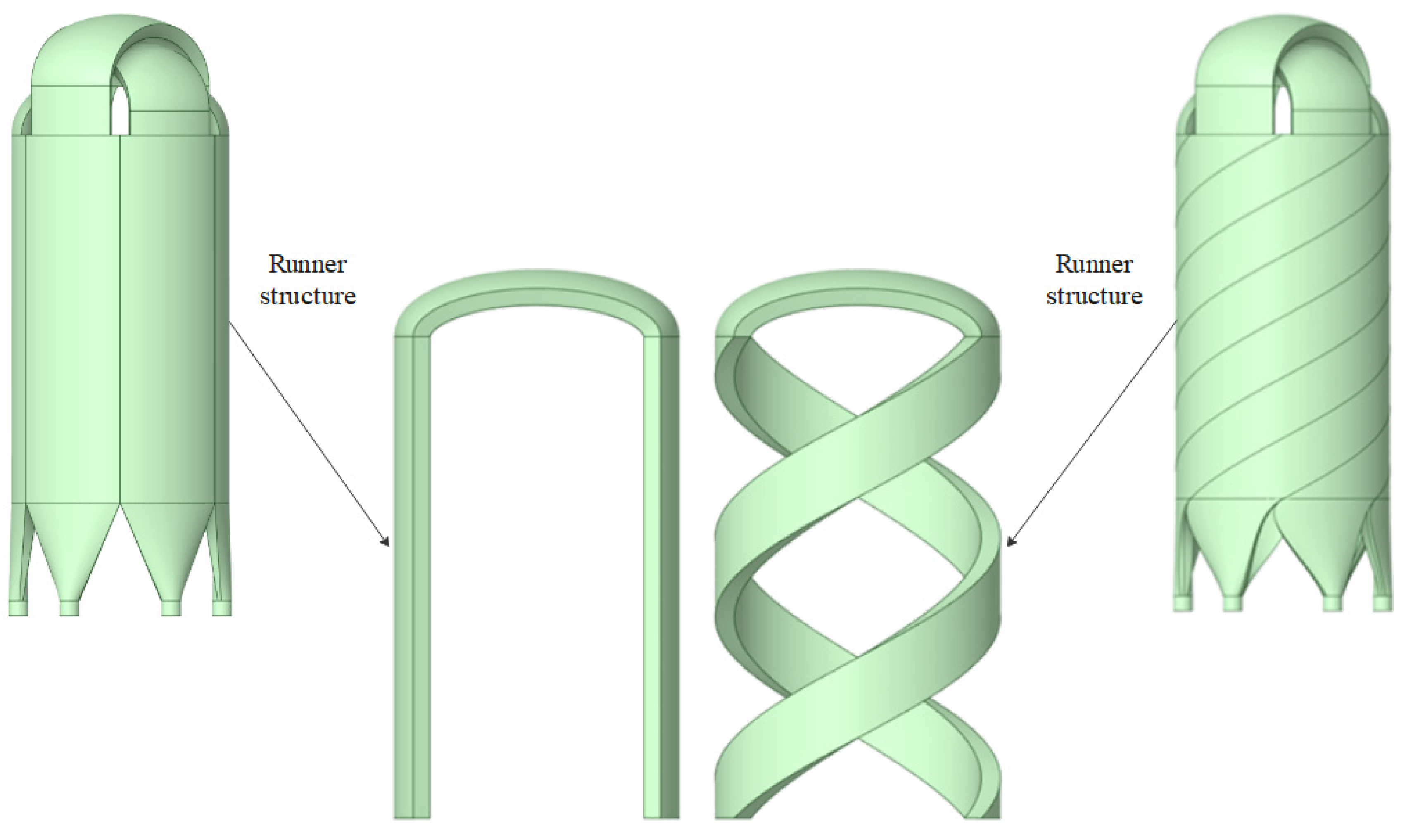
  • A new ACP with spiral flow was developed for active thermal insulation in comparison to the straight ACP, while the operating time can be prolonged by 30%, reaching over 160 min. Simultaneously, the heat−absorption rate drops by 1.8 W, on average, and the average TCF of the spiral−ACP case increases by 1.62 times compared with that of the straight−ACP case.
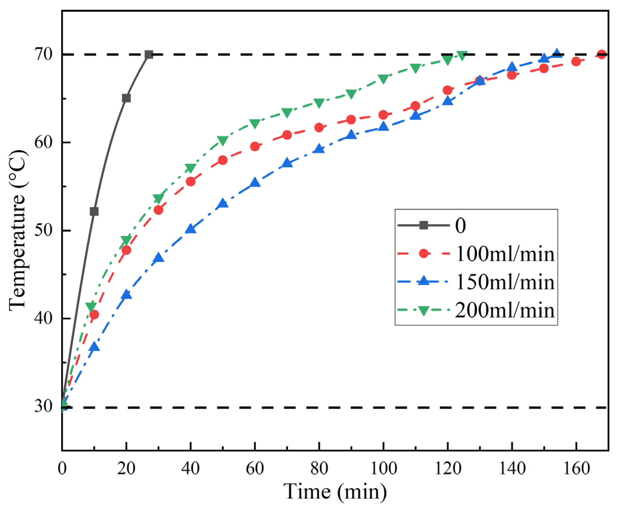
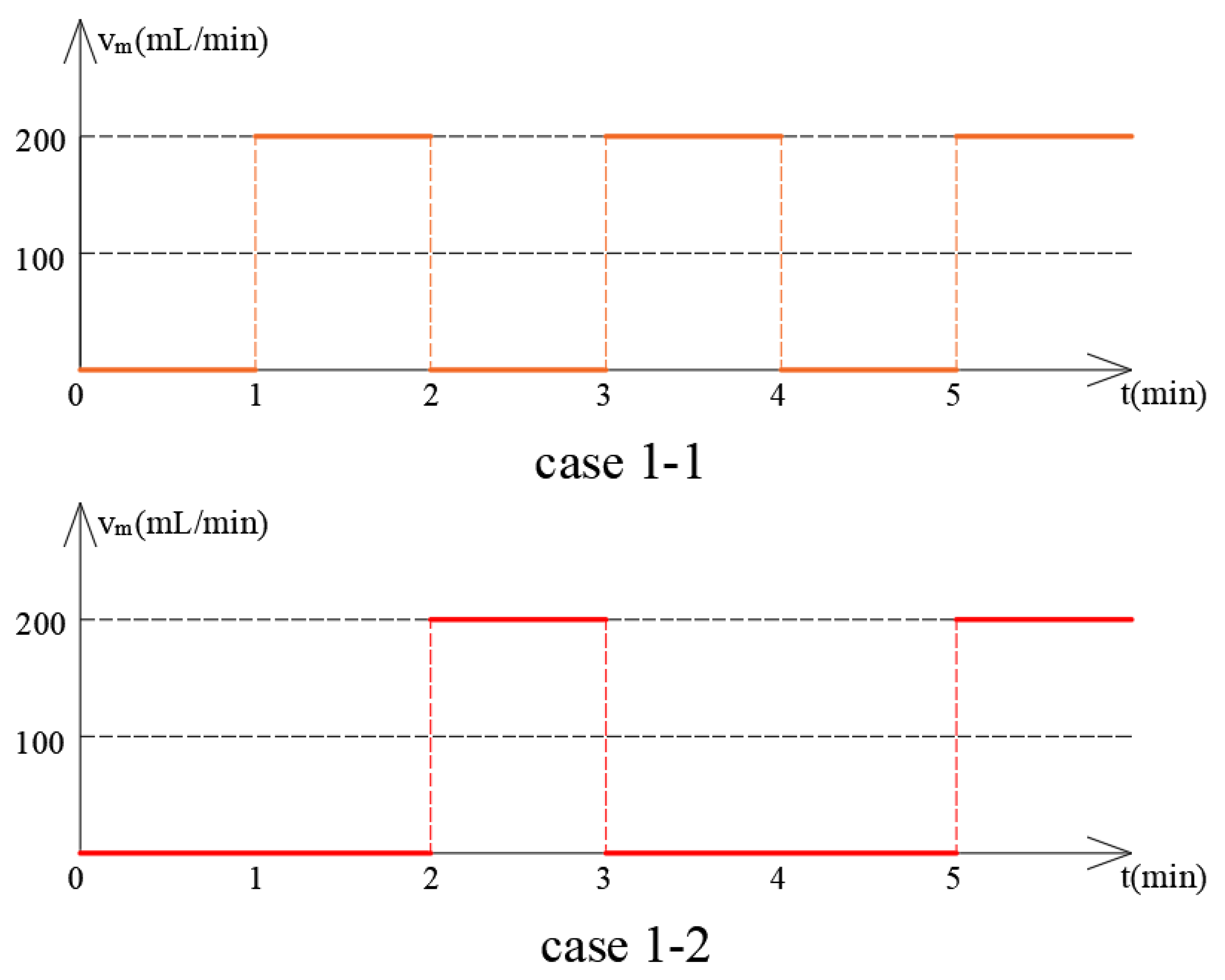
  • The effect of the working−medium flowrate on the thermal protection was also tested. The case with lowest flowrate, vm = 100 mL/min, provides the longest operating time due to the associated savings in PCM consumption. Consequently, the intermittent flowrate with 1 min of operation at vm = 100 mL/min and a 2−minute w stop (case 1–2) can further extend the operating time by 126.6%, reaching 5 h.
It should be noted that the thickness of the ACP and AM might greatly affect the thermal−protection effect. The numerical method is more appropriate, effective and cost−efficient for parametrical study, which will be discussed in the near future. Furthermore, the effect of the incline angles of the spiral design in combination with other parameters should be further analyzed.

Author Contributions

Investigation, S.M.; data curation, S.M. and S.Z.; writing, S.M.; validation, S.Z.; supervision, J.W.; conceptualization, Y.Z. and W.C.; review & editing, W.C.; supervision, Q.W. All authors have read and agreed to the published version of the manuscript.

Funding

The work is financially supported by the National Key R&D Program of China (No. 2020YFA0710500).

Data Availability Statement

Data is unavailable due to privacy or ethical restrictions.

Conflicts of Interest

The authors declare no conflict of interest.

Nomenclature

cspecific heat capacity, J/(kg·K)
Mvariables and a function of the independent parameters
qheat−absorption rate
Tinternal temperature, K
Tooutlet temperature, K
Tiinlet temperature
Tcrcritical temperature, K
Tststarting−record temperature, K
ttime variation, min
Ttemperature variation, K
vtemperature−increase rate, K/min
vmmass flowrate, kg/min
nnumber of monitored temperatures
xdifferent parameters
Greek symbols
αxerrors for each parameter
αMerrors for each variable
βtemperature−variation rate
λtemperature−control factor
δtemperature−difference ratio
Abbreviations
ACPannular cooling plate
ATISactive−thermal−insulation system
AMaerogel mat
PCMphase−change material
PLApolylactic acid
TCFtemperature−control factor
TVRtemperature−variation rate

References

  1. Qian, J.; Wang, J.; Li, S. In World’s Oil Shale Available Retorting Technologies And The Forecast Of Shale Oil Production. In Proceedings of the The Eighteenth International Offshore and Polar Engineering Conference, Vancouver, BC, Canada., 6–11 July 2008. [Google Scholar]
  2. Suyun, H.; Wenzhi, Z.; Lianhua, H.; Zhi, Y.; Rukai, Z.; Songtao, W.; Bin, B.; Xu, J. Development potential and technical strategy of continental shale oil in China. Pet. Explor. Dev. 2020, 47, 877–887. [Google Scholar]
  3. Li, Y.C. Oil Production Engineering; Petroleum Industry Press: Beijing, China, 2009. [Google Scholar]
  4. Yeh, L. Review of heat transfer technologies in electronic equipment. J. Electron. Packag. 1995, 117, 333–339. [Google Scholar] [CrossRef]
  5. Xu, Y.; Xu, N.; Zhang, W.; Zhu, J. A multi−layer integrated thermal protection system with C/SiC composite and Ti alloy lattice sandwich. Compos. Struct. 2019, 230, 111507. [Google Scholar] [CrossRef]
  6. Fan, B.; Chen, S.; Yao, Q.; Sun, Q.; Jin, C. Fabrication of Cellulose Nanofiber/AlOOH Aerogel for Flame Retardant and Thermal Insulation. Materials 2017, 10, 311. [Google Scholar] [CrossRef] [Green Version]
  7. Wicklein, B.; Kocjan, A.; Salazar−Alvarez, G.; Carosio, F.; Camino, G.; Antonietti, M.; Bergstrom, L. Thermally insulating and fire−retardant lightweight anisotropic foams based on nanocellulose and graphene oxide. Nat. Nanotechnol. 2015, 10, 277–283. [Google Scholar] [CrossRef]
  8. Nemanic, V. Vacuum insulating panel. Vacuum 1995, 46, 839–842. [Google Scholar] [CrossRef]
  9. Ma, Y.; Shang, B.; Hu, R.; Luo, X. Thermal management of downhole electronics cooling in oil & gas well logging at high temperature. In Proceedings of the 2016 17th International Conference on Electronic Packaging Technology (ICEPT), Wuhan, China, 16–19 August 2016; pp. 623–627. [Google Scholar]
  10. Rafie, S. Thermal management of downhole oil and gas logging sensors for HTHP applications using nanoporous materials. In Proceedings of the Energy Nanotechnology International Conference, Santa Clara, CA, USA, 5–7 September 2007. [Google Scholar]
  11. Zhang, J.; Lan, W.; Deng, C.; Wei, F.; Luo, X. Thermal Optimization of High−Temperature Downhole Electronic Devices. IEEE Trans. Compon. Packag. Manuf. Technol. 2021, 11, 1816–1823. [Google Scholar] [CrossRef]
  12. He, J.; Wang, Q.; Wu, J.; Zhang, Y.; Chu, W. Hybrid thermal management strategy with PCM and insulation materials for pulsed−power source controller in extreme oil−well thermal environment. Appl. Therm. Eng. 2022, 214, 118864. [Google Scholar] [CrossRef]
  13. Lan, W.; Zhang, J.; Peng, J.; Ma, Y.; Zhou, S.; Luo, X. Distributed thermal management system for downhole electronics at high temperature. Appl. Therm. Eng. 2020, 180, 115853. [Google Scholar] [CrossRef]
  14. Shang, B.; Ma, Y.; Hu, R.; Yuan, C.; Hu, J.; Luo, X. Passive thermal management system for downhole electronics in harsh thermal environments. Appl. Therm. Eng. 2017, 118, 593–599. [Google Scholar] [CrossRef]
  15. Bennett, G.A. Active Cooling for Downhole Instrumentation: Design Criteria and Conceptual Design Summary; Los Alamos National Lab.: Los Alamos, NM, USA, 1986. [Google Scholar]
  16. Flores, A.G. Active Cooling for Electronics in a Wireline Oil−Exploration Tool; Massachusetts Institute of Technology: Cambridge, MA, USA, 1996. [Google Scholar]
  17. Gao, W.; Liu, K.; Su, Y.; Sheng, L.; Cao, C.; Dou, X.; Zhang, L. Active Cooling Method for Downhole Systems in High Temperature Environment. In Proceedings of the Active Cooling Method for Downhole Systems in High Temperature Environment, SPE Western Regional Meeting, San Jose, CA, USA, 23–26 April 2019. [Google Scholar]
  18. Soprani, S.; Haertel, J.H.K.; Lazarov, B.S.; Sigmund, O.; Engelbrecht, K. A design approach for integrating thermoelectric devices using topology optimization. Appl. Energy 2016, 176, 49–64. [Google Scholar] [CrossRef] [Green Version]
  19. Hughes, T.; Weerasinghe, R. CFD modelling of thermal management in downhole tools. In Proceedings of the UK HTC 2015, Bristol, UK, 7–8 September 2015. [Google Scholar]
  20. Sinha, A.; Joshi, Y.K. Downhole Electronics Cooling Using a Thermoelectric Device and Heat Exchanger Arrangement. J. Electron. Packag. 2011, 133, 041005. [Google Scholar] [CrossRef]
  21. Holbein, B.; Isele, J.; Spatafora, L.; Hagenmeyer, V.; Schulenberg, T. Heat Exchanger for Down−Hole Condensation Process Theoretical and Experimental Investigation, Considering Surrounding Fluid Properties. GRC Trans. 2016, 40, 449–456. [Google Scholar]
  22. Holbein, B.; Isele, J.; Spatafora, L. In Integrated cooling systems for an extended operation range of borehole tools. In Proceedings of the Transactions, Geothermal Resources Council, Annual Meeting, Reno, NV, USA, 20–23 September 2015. [Google Scholar]
  23. Bennett, G.A. Active Cooling for Downhole Instrumentation: Miniature Thermoacoustic Refrigerator; The University of New Mexico: Albuquerque, NM, USA, 1991. [Google Scholar]
  24. Alrumaidh, A.; Abushaqra, A.; Elghoneimy, M.; Nabhan, M. Studying the cooling effect of nitrified drilling fluid on bottom−hole assembly while drilling high−pressure, high−temperature wells. In Proceedings of the SPE Middle East Oil & Gas Show and Conference, Manama, Kingdom of Bahrain, 9 May 2017. [Google Scholar]
  25. Verma, S.; Elias, Q. Thermal management of electronics used in downhole tools. In Proceedings of the SPE Annual Technical Conference and Exhibition, San Antonio, TX, USA, 8–10 October 2012. [Google Scholar]
  26. Jakaboski, J.-C. Innovative Thermal Management of Electronics Used in Oil Well Logging; Georgia Institute of Technology: Atlanta, GA, USA, 2004. [Google Scholar]
  27. Ling, Z.; Wang, F.; Fang, X.; Gao, X.; Zhang, Z. A hybrid thermal management system for lithium ion batteries combining phase change materials with forced−air cooling. Appl. Energy 2015, 148, 403–409. [Google Scholar] [CrossRef] [Green Version]
  28. Qin, P.; Liao, M.; Zhang, D.; Liu, Y.; Sun, J.; Wang, Q. Experimental and numerical study on a novel hybrid battery thermal management system integrated forced−air convection and phase change material. Energy Convers. Manag. 2019, 195, 1371–1381. [Google Scholar] [CrossRef]
  29. Zhang, C.; Qin, J.; Yang, Q.; Zhang, S.; Bao, W. Design and heat transfer characteristics analysis of combined active and passive thermal protection system for hydrogen fueled scramjet. Int. J. Hydrog. Energy 2015, 40, 675–682. [Google Scholar] [CrossRef]
  30. Wang, H.Z.; Jiang, L.I.; Qin, F.; Wei, X.G. Investigation on combination of active and passive thermal protection for RBCC engine. J. Solid Rocket. Technol. 2015, 178, 369–382. [Google Scholar]
  31. Marley, C.D.; Driscoll, J.F. Modeling an Active and Passive Thermal Protection System for a Hypersonic Vehicle. In Proceedings of the 55th AIAA Aerospace Sciences Meeting, Grapevine, TX, USA, 9–13 January 2017. [Google Scholar]
  32. Gou, J.-J.; Chang, Y.; Yan, Z.-W.; Chen, B.; Gong, C.-L. The design of thermal management system for hypersonic launch vehicles based on active cooling networks. Appl. Therm. Eng. 2019, 159, 113938. [Google Scholar] [CrossRef]
  33. Li, W.Q.; Qu, Z.G.; He, Y.L.; Tao, Y.B. Experimental study of a passive thermal management system for high−powered lithium ion batteries using porous metal foam saturated with phase change materials. J. Power Sources 2014, 255, 9–15. [Google Scholar] [CrossRef]
  34. Gulfam, R.; Zhang, P.; Meng, Z. Advanced thermal systems driven by paraffin−based phase change materials—A review. Appl. Energy 2019, 238, 582–611. [Google Scholar] [CrossRef]
  35. Feng, L.; Zhou, S.; Li, Y.; Wang, Y.; Zhao, Q.; Luo, C.; Wang, G.; Yan, K. Experimental investigation of thermal and strain management for lithium−ion battery pack in heat pipe cooling. J. Energy Storage 2018, 16, 84–92. [Google Scholar] [CrossRef]
  36. Yuan, F.; Li, M.-J.; Ma, Z.; Jin, B.; Liu, Z. Experimental study on thermal performance of high−temperature molten salt cascaded latent heat thermal energy storage system. Int. J. Heat Mass Tran. 2018, 118, 997–1011. [Google Scholar] [CrossRef]
Figure 1. Insulation mechanism with hybrid technology, including passive and active strategies.
Energies 16 01231 g001
Figure 2. Illustration of experimental system. (a) Schematic diagram. (b) Actual setup.
Energies 16 01231 g002
Figure 3. Schematic of spiral−ACP structure.
Energies 16 01231 g003
Figure 4. Results of DSC measurement of paraffin RT60.
Energies 16 01231 g004
Figure 5. Diagram of cases with different ACP layouts.
Energies 16 01231 g005
Figure 6. Comparison of thermal−protection performances with different insulation layouts. (a) Inner−wall temperature. (b) Phase change of absorbed heat.
Energies 16 01231 g006
Figure 7. The TCF and TVR with different insulation layouts.
Energies 16 01231 g007
Figure 8. Comparison of thermal−protection performances with different ACP structures. (a) Inner−wall temperature. (b) Phase change of absorbed heat.
Energies 16 01231 g008
Figure 9. Comparison of TCF and TVR between cases with spiral ACP and straight ACP.
Energies 16 01231 g009
Figure 10. Comparison of thermal−protection performances with different flowrates.
Energies 16 01231 g010
Figure 11. Control logic of intermittent flow.
Energies 16 01231 g011
Figure 12. Comparison of thermal−protection performances with different supply methods for working medium. (a) Inner−wall temperature. (b) Temperature−control coefficient.
Energies 16 01231 g012
Disclaimer/Publisher’s Note: The statements, opinions and data contained in all publications are solely those of the individual author(s) and contributor(s) and not of MDPI and/or the editor(s). MDPI and/or the editor(s) disclaim responsibility for any injury to people or property resulting from any ideas, methods, instructions or products referred to in the content.

