
Designing Reconfigurable Cyber-Physical Systems Using Unified Modeling Language


Institute of Control & Computation Engineering, University of Zielona Góra, 65-516 Zielona Góra, Poland
Energies 2023, 16(3), 1273; https://doi.org/10.3390/en16031273
Submission received: 30 December 2022
/
Revised: 22 January 2023
/
Accepted: 24 January 2023
/
Published: 25 January 2023
(This article belongs to the Special Issue Control Part of Cyber-Physical Systems: Modeling, Design and Analysis)
Abstract
:Technological progress in recent years in the Cyber-Physical Systems (CPSs) area has given designers unprecedented possibilities and computational power, but as a consequence, the modeled CPSs are becoming increasingly complex, hierarchical, and concurrent. Therefore, new methods of CPSs design (especially using abstract modeling) are needed. The paper presents an approach to the CPS control part modeling using state machine diagrams from Unified Modelling Language (UML). The proposed design method attempts to combine the advantages of graphical notation (intuitiveness, convenience, readability) with the benefits of text specification languages (unambiguity, precision, versatility). The UML specification is transformed using Model-Driven Development (MDD) techniques into an effective program in Hardware Description Language (HDL), using Concurrent Finite State Machine (CFSM) as a temporary model. The obtained HDL specification can be analyzed, validated, synthesized, and finally implemented in Field Programmable Gate Array (FPGA) devices. The dynamic, partial reconfiguration (a feature of modern FPGAs) allows for the exchange of a part of the implemented CPS algorithm without stopping the device. But to use this feature, the model must be safe, which in the proposed approach means, that it should possess special idle states, where the control is transferred during the reconfiguration process. Applying the CFSM model greatly facilitates this task. The proposed design method offers efficient graphical modeling of a control part of CPS, and automatic translation of the behavior model into a synthesizable Verilog description, which can be directly implemented in FPGA devices, and dynamically reconfigured as needed. A practical example illustrating the successive stages of the proposed method is also presented.
1. Introduction
Cyber-Physical Systems (CPSs) refer to a new generation of systems that integrate cybernetic aspects with physical processes [1]. The increasing complexity of components and the use of more advanced technologies for sensors and actuators generate a serious challenge for building next-generation control systems, especially “smart” systems. In particular, theory and tools are needed for developing cost-effective methods to design, analyze, and verify components at various levels of abstraction [2]. In our daily lives, we are surrounded by countless examples of CPSs [3,4,5,6]. For instance, vehicles contain tens of electronic components (e.g., control units, sensors, actuators) that perform tasks ranging from the control of mechanical aspects of the vehicle, such as engine management, anti-lock brake system, suspension, and transmission, etc., to tasks such as communication, navigation, and entertainment [7]. Another CPS example could be a smart home system that enables intelligent management of devices and systems usually found at home (e.g., alarm system, local alternative-energy generation system, heating system, air conditioning system). Moreover, present-day CPSs are expected to be safe, effectively protecting user data, energy efficient, small in size, useful, and easily adaptable to changing conditions. Especially the latter requirement is demanding. Therefore, a promising solution seems to be dynamically reconfigurable hardware. A common argument for reconfigurable architecture is the specialization of processing elements that can be adapted to application functions to minimize delay, control cost, and improve data locality. Another key benefit is the hardware reuse to minimize the area and the static power and cost. Further advantages such as hardware updates in long-life products and self-healing capabilities are also often mentioned [8,9]. Moreover, in case of context changes (e.g., environment or application functionality), the self-adaptive technique can be applied as a solution to fully benefit from the dynamic reconfigurability of a system [10].
Recent advances in design automation and semiconductor manufacturing have resulted in the potential to build increasingly complicated systems that consequently are difficult to develop and test [11]. With the increasing complexity of CPSs and the related software components, there is a felt need to develop design flows toward implementation, starting from higher-level modeling [12,13]. Modeling is gaining popularity as an approach to the design of complex systems, raising the level of abstraction at which developers work, and promising improved quality and increased productivity through automation [11]. An even more effective and convenient approach involves the use of many various, automatically generated models, each at a different level of abstraction. Moreover, many implementation tools require text specification of the system like Hardware Description Languages—HDLs (used for the implementation of Field Programmable Gate Array—FPGA devices) or programming languages (needed for the implementation in microcontrollers like Arduino or Raspberry Pi). Therefore, there is a need to model at a high level of abstraction and then translate the high-level graphical model into the low-level code model (expressed in HDL or programming language). These goals can be obtained using a widely recognized graphical modeling language like Unified Modelling Language (UML) and the Model-Driven Development (MDD) approach.
UML [14] is now one of the most important software engineering standards, but it is broad enough in scope to model embedded systems (including CPSs) [15,16]. The application of UML in the context of embedded systems has attracted growing interest in recent years [17,18,19]. Using MDD raises the level of abstraction in all phases of system development [13]. The adoption of an MDD approach (and Model-Driven Architecture—MDA [20] as well) opens the ability of automatic code generation and manual writing and analysis can be substituted by specialized tools [13]. However, a unified development methodology for CPS has not been standardized yet, so there is a need for a standardized design approach (e.g., using CPS metamodels [21]) especially because of the multidisciplinary nature of CPSs [22,23].
This paper presents an approach that raises the level of abstraction using a standardized high-level design language to build the UML state machine model, and then translate it, using a temporary Concurrent Finite State Machine (CFSM) model, into the HDL code model. This approach allows for precise and unambiguous specification of the designed system and enables software validation, synthesis, and finally effective implementation of the system in the reconfigurable FPGA. Even though the transformation from the UML model into the HDL model (expressed very often in Very High-Speed Integrated Circuits Program HDL—VHDL or Verilog language) is present in the literature, there is still a gap because very often the obtained HDL description cannot be implemented in a real device (is non-synthesizable) or the entire system is described on the detailed, low-abstraction level in one text file (is non-modular), which makes verification, analysis, and optimization of the system very difficult [15,24]. To face this challenge, the paper presents an approach to automatic source code generation using MDD techniques. It starts from the specification of the control part of the reconfigurable CPS described with the use of a UML state machine diagram. Then it is translated using a temporary CFSM model, into modular HDL code (in Verilog language)—ready for implementation in reconfigurable FPGA devices. The novelty of the proposed approach lies primarily with the use of the CFSM model—it perfectly suits the need to design a safe model, because it provides special idle states, where the control can be safely transferred during the dynamic partial reconfiguration process.
The main contributions proposed in the paper can be summarized as follows:
- a novel UML-based design method for the reconfigurable CPSs is proposed;
- the presented approach is oriented toward hardware implementation of the CPS control part in reconfigurable FPGA devices;
- the proposed CPS design framework utilizes MDD techniques (used to models transformation from a high-level graphical model into a code model) combined with the use of CFSM as a temporary model;
- MDD approach with the use of MDA enables automatic model generation from UML state machine diagram through CFSM model into modular and synthesizable Verilog specification;
- CFSM model applied idle states which are perfect to obtain a safe model, that is ready for dynamic partial reconfiguration (exchanging part of the control algorithm implemented in FPGA without switching the device off);
- a practical case-study example (reconfigurable smart home system) illustrating the successive stages of the proposed method is presented.
The remainder of the paper is structured as follows: Section 2 presents the related works; Section 3 describes in detail the proposed method; Section 4 contains a practical example (case study) of the presented approach; Section 5 contains a short discussion about the proposed method, and finally, Section 6 concludes the paper.
2. Related Works
Model-based system engineering is a well-known approach to the development of complex systems. It has features for the reduction of development complexity, enhanced productivity, and efficient management of change, and therefore is very often used also for the CPSs design [25,26,27]. There are also many methods using MMD and UML (or its extension like Systems Modeling Language—SysML [28] or MARTE profile [29]). Unfortunately, the frequently generated specification cannot be implemented in reconfigurable FPGA devices or even synthesized, because it is not in an HDL form. This drawback can be found for example in [30], where authors propose an approach of using SysML mixed with MDD techniques to generate Discrete Event System Specification (DESS). Even if DESS models are executable, the synthesis or implementation in FPGA devices is impossible. A similar problem can be found in [31], where also SysML is used. Based on the SysML model, the output system description in the Modelica text model is obtained. However, this model cannot be used for the implementation (especially using FPGA devices). Similar disadvantages of using SysML regard the solution presented in [32], where authors propose an interesting approach to modeling a swarm intelligence algorithm.
In [13] the authors propose an MDD-based approach to embedded system design and analysis. The proposed assertion-based verification method produces an executable code in the programming language C. Even if the obtained C code model is executable, implementation in FPGA is impossible, and thus the use of reconfigurable features too.
IBM Engineering Systems Design Rhapsody [33] is one of the most popular tools for modeling digital microsystems. It can generate source code, but it is insufficient for the modeling of large and complex CPSs. Other commercial tools to generate Verilog are StateCAD [34] and Simulink HDL Coder [35]. The first one has its graphical notation representing state diagrams as bubble diagrams. It generates Verilog and VHDL code for simulation and synthesis. The second one generates synthesizable Verilog and VHDL code from Simulink models, Stateflow charts, and embedded Matlab code. The drawback of both tools is the lack of UML notation, which preclude the use of the wealth of modeling aspects available in the UML state machine diagrams (e.g., history pseudostates).
MODCO [36] is another interesting method and tool for the modeling of embedded systems and CPSs. It uses MDD techniques to define high-level model-based system descriptions that can be implemented in either hardware or software. Thus, it can transform UML state diagrams directly into synthesizable VHDL. UML state machines are used to describe system behaviors. Unfortunately, in the presented approach only a small subset of UML state machine diagrams elements is used, and therefore modeling hierarchical and concurrent models are impossible.
Another modeling tool MODEASY [24] allows transforming UML state machine diagrams, augmented using component diagrams, into a synthesizable VHDL description. The transformation rules are defined on the metamodel level. Two transformations are performed: from the UML model into state diagrams, and state diagrams into VHDL description. Moreover, the authors use a model-to-text transformation approach. However, not all UML state machine diagram elements (e.g., internal transitions, enter or exit state activities, etc.) are supported. Another disadvantage of MODEASY is that the obtained VHDL model is expressed in one text file. This makes the generated description difficult to analyze and manual verification. Furthermore, even a small change in the initial model forces the generation of the whole output specification again.
Interesting research can be found in [37], where based on the UML/MARTE model (on the high level of abstraction) the C++ specification of the system is generated. This output code is devoted to distributed CPSs. The authors using the semantics available in the Robotic Operating System framework extend the Aspect-Oriented Model Driven Engineering for Real-Time Systems design approach to support the C++ code generation in terms of robotic systems implementation. Unfortunately, the C++ output code cannot be used for reconfigurable CPS implementation in FPGA devices, and therefore also the reconfigurable feature cannot be applied using this approach.
A very promising solution can be found in [38], where a model-driven framework for the design and verification of embedded systems is presented. The authors propose a UML profile for SystemVerilog (UMLSV) to model the design and verification requirements. Such an approach allows for system modeling along with the verification aspects at a higher level of abstraction. Finally, the synthesizable system description in the form of SystemVerilog language is obtained. However, to use the framework a dedicated Java software Accelo is needed, or the UMLSV profile can be applied in many modeling editors (e.g., Papyrus, MagicDraw, etc.) [38]. Moreover, the designer must be familiar with the developed UMLSV profile, which may be seen as a limitation.
Another approach of using UML and MARTE (UML profile) to generate Verilog code is presented in [39]. The authors propose a framework for the specification of requirements with the use of graphical modeling languages (UML/MARTE) as temporal and logical patterns. The presented approach allows for ambiguity elimination and automatic verification of the design. Unfortunately, the proposed framework is not suitable for the generation of the behavioral code, because it only focuses on the system verification aspects and cannot be implemented in a real device (like FPGA).
Although researchers have put great efforts into the field of model-based system engineering, it is still a challenging area. It is always difficult to select appropriate modeling techniques and UML elements to model embedded system requirements [33]. All the works mentioned above have some limitations, but the main drawback that concerns almost every method seems to be the generation of non-synthesizable or non-modular HDL code. This significantly hinders the verification, analysis, optimization, and dynamic reconfiguration of CPS. Moreover, many of the presented approaches do not support all the efficient modeling structures from UML state machine diagrams, like (shallow or deep) history pseudostates, composite states, internal state activities, local or internal transitions, etc. The proposed method (presented in detail in the next section) tries to fill this gap.
3. The Proposed Method
The proposed method attempts to combine the benefits of text specification languages (unambiguity, precision, versatility) with the advantages of graphical notation (readability, intuitiveness, convenience). The paper presents the notion of behavioral synthesis of models expressed as UML state machine diagrams. The proposed approach is based on a method described in [40] and relies on a model-driven framework developed for the design of the CPS control part (Figure 1). The framework also applies an authors’ U2V tool (the name of the tool is an abbreviation of “UML to Verilog”).
Starting from informal CPS requirements, using a UML editor, the designer creates a UML state machine model and exports it into an XML file (an XML export option compliant with the XML Metadata Interchange—XMI specification [41] is present in almost all UML editors). The XML description of the model is the input to the U2V tool, which first transforms the UML model into a CFSM model. This transformation contains three important phases: state machine decomposition, augmentation of the obtained FSMs with special states and signals, and finally, the building of a CFSM model. Then the obtained CFSM model is applied to the automatic generation of HDL. This set of HDL files contains a synthesizable and modular CPS description in Verilog. Then the simulation phase is performed (using a specialized tool like Active-HDL from Aldec, Henderson, NV, USA) to ensure that the obtained specification meets all the initial CPS requirements. If the simulation shows that the initial requirements are not satisfied, then corrections of the UML model are needed (as shown in Figure 1). Next, using synthesis tools (e.g., Xilinx ISE from Xilinx, San Jose, CA, USA), the synthesis and finally implementation of the target FPGA is performed. In the following subsections of the paper, the stages of the proposed method will be presented in detail.
3.1. UML Modeling
The current version of UML (2.5.1) contains 14 types of diagrams [14]. From the CPS modeling view, the most important seems to be the state machine diagram, because it applied the concepts of a state and a state machine.
The first stage of the proposed method is to create an appropriate UML state machine diagram that describes the behavior of the designed control part of the CPS. Figure 2 shows an exemplary UML state machine diagram at the highest level of the hierarchy (without the internal details) and Figure 3 presents the same system as the fully-detailed diagram. It should be noted that in Figure 2 state “A” is a simple state, and “B” and “C” are composite states (depicted by two small, connected circles). Signals x1, x2, and x3 are used to activate transitions between states (they are referred to as guards of the transition). For example, when signal x1 is active (the value of logical “1”) the control is transferred from state “A” into state “B”. It is worth mentioning that the transition from state “C” into “B” has no visible transition guard, but in fact, it is a hidden completion event [14] connected with the transition. In other words, this transition is fired when the control is transferred from the state “C2” into the final state (Figure 3). Similar situation is with the transition without a guard from the state “B” into “C” (this transition has invisible completion event which will occur when the final state in composite state “B” will be achieved).
In general, in the proposed method, the transition guard can contain names of signals and logical operators like “+” (disjunction), “*” (conjunction), and “!” (negation).
To some states, output signals (y1–y8) are assigned. For example, when the state “B2” is active, output signal y1 is activated, and similarly, in the state “B4” two signals y3 and y4 are activated simultaneously. Changes in the CPS’s environment (e.g., signals from the physical part of the CPS) are represented by input signals (x1–x16). The controller (in the rest of the paper, the term “controller” will be used interchangeably with the “control part of the CPS”) responds to these changes utilizing activation or deactivation of the corresponding output signals. Also, as a result of internal operations in the state, or realization of the transition, the controller may change the values of output or internal signals. In the presented approach, in the description of conditions, transition effects, or internal activities of states, the names of signals (internal, input, or output) as well as their negations can be used.
3.2. Model Transformation
Figure 4 presents the full model transformation path of the proposed method, which applies an MDD approach and MDA. Please note, that the model transformation rules are defined at the metamodels level [42]. According to the MDA definition [20], the initial system requirements can be treated as a Computational Independent Model (CIM), the UML state machine diagram as a Platform Independent Model (PIM), the CFSM model as a Platform Specific Model (PSM), and the final Verilog description as a code model.
In the first step, the designer uses a UML editor and based on the informal specifications and system requirements (CIM), builds a behavioral model with the use of a UML state machine diagram (PIM). Then the transformation from PIM into PSM is performed. In the last phase, the translation from PSM into a code model is accomplished. It is possible to automatically generate different code models using only one PSM and appropriate tools. In the presented method, the PSM is a source for a Verilog generation, but it could also be used for VHDL, SystemC, and other HDLs or even programming languages (like C/C++, Java, Python, etc.), which is the subject of further research by the authors.
The detailed transformation path from PIM (UML state machine model) into PSM (CFSM model) consists of 3 stages:
- State machine decomposition.
- Augmenting the obtained FSMs.
- Building the CFSM model.
Each of the stages mentioned above will be described in more detail.
3.2.1. State Machine Decomposition
First, the state machine model is decomposed into several FSMs. A state machine decomposition algorithm is presented in Figure 5 in the form of a UML activity diagram. It is worth noting that the state machine region search function is defined recursively. Figure 6, Figure 7 and Figure 8 show the exemplary FSMs—results of the state machine (from Figure 3) decomposition.
3.2.2. Augmenting the Obtained FSMs
In the next step the FSM on the highest hierarchy level is chosen (Figure 6). It will play a coordinating (master) role with all other (slave) FSMs. The master FSM was named Process.
Then augmenting the master FSM with additional signals is performed. These special signals are associated with the activity of each of the slave automata (in Figure 6 there are signals inB and inC written in dark red boldface). These signals are only added in the states that are represented by composite states in the UML state machine diagram (here there are states “B” and “C”).
Next, each slave FSM is augmented with idle states (in Figure 7 and Figure 8 marked with a violet background), transitions to these idle states, and special signals (written in dark red boldface). What is worth noting, the idle state is activated when the superior state is inactive. For example, if the control is moved from state B into C (Figure 6), in the slave FSM B_region (Figure 7a) the idle state is activated, thanks to using one of the transitions with the signal !inB. Moreover, these idle states play an important role in the dynamic partial reconfiguration process of the CPS implemented in FPGA devices.
The synthesis of composite states with either shallow or deep history pseudostates is an important issue because using history pseudostates aids in the modeling of exception handling. To “remember” the last active state additional idle states and transitions are required. Figure 8 presents an example of a slave FSM (C_region2) with implemented history mechanism. The number of idle states used to store the last active state strictly depends on the amount of FSM states (one idle state for each FSM state). The history mechanism implementation was inspired by [43].
3.2.3. Building a CFSM Model
As a result of the previous stages, a concurrent and connected set of FSMs (CFSM model) is achieved (Figure 9).
3.3. Transformation of the CFSM Model into Verilog
In the next step, a set of Verilog files are produced. These Verilog files represent all decomposed FSM automata. The description of FSM in HDL can be performed in several different ways [42]. Most popular approaches utilize one, two, or three processes in HDL. The proposed method uses two processes and applies the Moore machine [44] theory. The output specification generated in Verilog can be simulated and synthesized and finally implemented in a real FPGA device.
3.4. Simulation
In this step, the verification using an external simulation tool (e.g., Vivado from Xilinx, Active-HDL from Aldec) of the designed system is performed, and the obtained results are compared with the user requirements. If the modeled system does not satisfy the initial CPS requirements, then corrections in the UML model should be made.
3.5. Hardware Implementation
Once the designed system is verified, it can be synthesized (using a special synthesis tool, e.g., Xilinx ISE from Xilinx) and implemented in an FPGA device. To prepare the model for the dynamic partial reconfiguration, using the specialized tool (like Xilinx ISE or Vivado from Xilinx), the reconfigurable area of the FPGA device should be selected. Then, the full bitstream is generated. This bitstream is responsible for the initial implementation of the FPGA (both the static and dynamic parts of the device are physically programmed).
In the situation, when the initial CPS requirements are changed, there is no need to prepare a new version of the whole system, but only of the changed algorithm (called context [45]). In this case, the designer creates a UML state machine diagram for the changed fragment only and, according to the design framework from Figure 1, generates the output Verilog file. This file is sufficient to create an appropriate partial bitstream for the new context. Using this file, the dynamic partial reconfiguration (without switching the whole device off) of the FPGA can be done.
4. Case-Study Example
In this section, the benefits of the proposed method and its usefulness in the safe FPGA reconfiguration process are presented. The reconfigurable CPS under investigation is the Smart Home System (SHS) which was designed based on Home Area Network [45].
4.1. SHS Description
The SHS was planned for a family living in a flat with a living room with an open kitchen, bathroom, bedroom, small hall, and balcony. The SHS is responsible for the management of home appliances (connected to the SHS controller), the safety of residents (alarm system role), increasing the convenience of life and reducing the cost of electricity, and reducing the electrical load using Demand Side Response (DSR) approach [46] when the EMERGENCY signal is received. This signal comes from the Distribution System Operator (DSO). Moreover, there is an additional condition that in the situation when initial CPS requirements change, the SHS should be partially reconfigured (exchange the part of the control algorithm responsible for the load reduction), which means without switching the system off. The SHS consists of (Figure 10):
- 14 binary sensors—two door sensors: D1 (on the front door) and D2 (balcony door), three window sensors: W1, W2, W3, two flood sensors: F1 (in the bathroom) and F2 (in the kitchen), smoke detector S1 (in the kitchen), dusk sensor T1 (on the balcony), five motion sensors: M1, M2, M3, M4, M5 (in each room),
- 14 controlled actuators—five light switches: L1, L2, L3, L4, L5 (in each room), alarm siren A1 (in the hall), and eight relay switches, which are connected to a fridge R1, dishwasher R2, and freezer R3 (in the kitchen), air conditioner R4 and desk lamp R5 (in the living room), two bedside lamps: R6 and R7 (in the bedroom) and washing machine R8 (in the bathroom),
- 1 SHS controller (all sensors and actuators are connected to the SHS controller).
The detailed SHS requirements are presented in Appendix A (including the meanings of the SHS signals shown in Table A1).
4.2. Design of the SHS Controller
First, based on the SHS requirements, the designer creates a UML state machine model that describes the behavior of the SHS. The UML state machine diagram of the SHS on the highest level of abstraction is shown in Figure 11, and the diagram with all details is presented in Figure 12. It should be noted that “Standby” and “Alarm” in the diagram are simple states, and “On” is a composite state. In the “Standby” no output signal is generated, while in the “Alarm” six output signals are active: A1, L1, L2, L3, L4, and L5.
The second stage is model transformation. The master FSM (Process) obtained after state machine decomposition can be found in Figure 13 and exemplary slave FSMs augmented with special signals and idle states in Figure 14. Figure 14a presents an exemplary slave FSM with implemented history mechanism (the FSM “remembers” the last active state). Finally, Figure 15 shows the obtained CFSM structure of the SHS.
Based on the CFSM model, a set of Verilog files is generated, and then compiled and verified using a software simulation tool (Active-HDL from Aldec). The simulation outcomes are presented in Figure 16. As can be seen in the simulation chart when the signal EMERGENCY occurred, the system reduced the electrical load by switching off the selected devices like the fridge, dishwasher, freezer, air conditioner, and washing machine.
Another situation presented in Figure 16 is when the system was in the “Guard” mode, and motion in the bedroom was detected (M5 = 1). The response of the SHS was the activation of the alarm, switching on the siren (A1 = 1), and the lights in the house (L1 = 1, L2 = 1, L3 = 1, L4 = 1, and L5 = 1). All obtained results were coherent with the UML state machine model and initial CPS requirements.
Finally, the SHS controller was synthesized and implemented in an FPGA device. For hardware verification, the board Nexys 4 DDR Artix-7 FPGA (with 100 MHz internal clock) from Digilent was chosen.
4.3. Dynamic Partial Reconfiguration
Let us assume that the initial CPS requirements are changed by the DSO, and therefore the functionality of the SHS should be modified. When the EMERGENCY signal occurs the fridge and air conditioner should not be switched off. Furthermore, there should be a delay in switching off the other devices. Usually, to meet the modified CPS requirements, the designer should correct the model, generate the whole Verilog specification again, verify the system using simulation tools, and finally with the use of a synthesis tool generates the new full bitstream. Then the SHS should be stopped and reconfigured.
However, thanks to the presented approach of designing reconfigurable CPS, the designer can prepare only a new model for the load-reducing module and produce the partial bitstream. Then the dynamic partial reconfiguration of the SHS controller can be done. What is worth noting, this dynamic reconfiguration process does not require switching off the whole CPS and can be performed when other modules of CPS are still working (including the alarm system).
Firstly, the UML state machine diagram (including two more states compared to Figure 12) for the new context (“Load reducing 2”) is created (Figure 17).
In the next step the translation of the UML model into FSM is performed and augmenting with the special signals and idle state is done (Figure 18). Next, based on the new FSM the Verilog file is generated, which can be verified with the use of software simulation and finally synthesized producing the partial bitstream.
Finally, the dynamic partial reconfiguration of the system can be done. In Figure 19 a screenshot of a hardware verification using an oscilloscope MSO 2024 from Tektronix is presented. As can be seen in Figure 19, first the DSO sent a REQ (reconfiguration request) signal to the SHS. The SHS controller in the load-reducing module moves the control into the idle state and responds with activation of the RAL (reconfiguration allowed) signal. Now, the dynamic partial reconfiguration can be safely done, and the load-reducing module can be replaced with the new context. It is worth emphasizing, that the rest of the system is still working (including the alarm system). In the presented scenario, during the reconfiguration process, the alarm system detected a motion in the living room (active signal from sensor M4), which activated the alarm siren (signal A1). After the successful dynamic partial reconfiguration process, the SHS controller continued its work but with the modified behavior of the load-reducing module.
5. Discussion
This section is devoted to a short discussion of the proposed method, its verification, limitations, and comparison to other existing approaches and tools.
5.1. Verification of the Proposed Method
The verification process of the proposed method (using some CPS benchmarks) was as follows:
- First, based on the user requirements, a system was modeled with the use of a UML state machine diagram.
- Then the state machine model using a temporary CFSM model was transformed into a synthesizable and modular Verilog specification.
- In the next step, using the Active-HDL tool, the correctness of Verilog files was verified.
- Then the simulation (with the use of Active-HDL) was done, and the obtained results were compared with the initial CPS requirements.
- Finally, using the Xilinx ISE environment, a synthesis process was carried out to check if the output specification can be truly synthesized.
The benchmarks used in the verification process are listed in [42]. In all cases, the obtained results were in line with the expectations.
5.2. Limitation and Scope of the Method
The first limitation of the proposed method could be seen in that, not every UML state machine element may be used to describe the CPS behavior. It should be noted that the UML was created to support software systems design and not strictly hardware/software systems. Therefore, some object-oriented UML elements (e.g., terminate pseudostate, which is used to model the situation when the object is destroyed) cannot be directly translated into the CPS design domain. Moreover, there could be a situation where, based on the initial requirements, a UML state machine model cannot be built because some specific, complex requirements (e.g., timing constraints) cannot be expressed in UML (but using other notations they can). So, the scope of the proposed method is limited to the CPS classes, which can be described with the state machines using UML elements.
Another disadvantage is that the presented approach is limited to modular UML diagrams, which means that the model cannot possess transitions crossing the borders of the states. But it is worth noting that this limitation is present in almost every UML-based design tool.
Implementation of the designed CPS as a synchronous system could be also seen as a drawback. One of them is the assumption that the rising edge of the clock signal plays a synchronization role in the system. It means that the clock signal synchronizes the moment when the change of the input signals (treated as transition guards) is examined. Moreover, the change of internal or output signals is also synchronized by the clock signal.
5.3. Comparison with Other Methods and Approaches
Existing methods and tools (some of them are discussed in Section 2) use different input models. Some of them need UML, some SysML, MARTE, and UMLSV [38], and others require the simultaneous use of a combination of a few languages/profiles. Moreover, some other languages and notations can be applied to model the control part of a CPS.
One of the most effective modeling tools is Petri nets [47] because they are intuitive, graphical notation with natural preservation of concurrent relations in the modeled CPS [48,49]. A Petri net is a directed bipartite graph with two types of vertices: places (denoted by a circle) and transitions (usually represented by a rectangle) connected by directed arcs. A place may hold a token (then it is called the “marked place”). The state of the Petri net-based system is a set of simultaneously marked places [50]. Moreover, Petri nets are supported by many analysis and validation methods [51,52]. However, the decomposition of the Petri net-based model into a set of sequential FSMs is not a trivial task [50]. In the presented approach the modular state machines from UML are used, where decomposition is much easier in comparison to Petri nets. It is because the modular UML state machine model requires the designer to implicitly (and often unconsciously) split the system into smaller, hierarchical, and concurrent modules, which greatly facilitates the further decomposition of the state machine. It is worth noting that there is also a possibility of using both UML and Petri net models [53] or transforming one model into another [54,55] (it is possible to create a UML state machine model, next translate it into a Petri net model, and then analyze it with the use of fast and effective analysis and verification methods [56,57]).
Because the proposed method applies the “pure UML” models, therefore for further comparison only UML-based approaches were selected. Moreover, nowadays CPSs are becoming even more complex [58], therefore besides using UML as an input model, a modern, effective method should also support the design of hierarchical and concurrent systems and use the MDD approach.
An important characteristic is also the ability to generate output specifications in synthesizable HDL code (e.g., Verilog, VHDL, SystemC). Some methods allow for generating system descriptions in HDL, but not in synthesizable form. Such output specification cannot be further implemented in programmable or reconfigurable devices, and it can be used only for a computer simulation.
Another worth-noting feature is the modularity of the generated output specification. Placing the whole behavioral description in a single file causes the verification of such a system very difficult, with the specification being unreadable and the possibility of introducing corrections being questionable. Splitting the output specification into several smaller interdependent files facilitates analysis, verification, simulation, and optimization of each component separately (the exemplary methods of optimization of FSM are proposed in [59,60]). Even if errors are found, it is possible to replace only the faulty module and there is no need to generate the entire model again.
Finally, a very important advantage of modular system behavior implemented in FPGA is also the ability of dynamic partial reconfiguration because it provides several benefits like reducing power consumption and costs, accelerating configurable computing, and improving fault tolerance of the device [61]. Therefore, in our opinion, modularity is one of the biggest advantages of the proposed method.
The detailed comparison of the proposed method (together with the authors’ U2V tool) with selected methods/tools is summarized in Table 1.
As Table 1 shows, the method most similar to the one presented in the paper is MODEEASY [24]. The biggest difference lies in the subsets of UML elements used to specify embedded system requirements. In both methods, only a selected subset of UML elements can be utilized, which can be considered as a limitation for the designer. In Table 2 a detailed comparison of the supported UML elements by these two similar methods is presented.
In the proposed method, compared to MODEASY, the use of some kinds of pseudostates like join, fork, junction, and choice is prohibited, which can be treated as a drawback of the method. However, in [42] for each of these pseudostates alternative, semantically equivalent constructions were proposed. Though on the other hand, MODEASY does not support state entry and exit behaviors, which are very useful modeling tools.
6. Conclusions
In the paper, the UML-based design method for reconfigurable CPS is presented. The system is specified using the UML state machine diagram and implemented in reconfigurable FPGA devices. Thanks to the MDD approach, starting with a UML model, through the temporary CFSM model, a set of Verilog files is obtained. The description of the control part of CPS generated in HDL can be synthesized and implemented in reconfigurable devices (e.g., FPGAs). Using CFSM as a temporary model (thanks to using special idle states) greatly facilitates the design of systems that are safe and ready for dynamic partial reconfiguration (i.e., exchanging the part of the implemented control algorithm without switching the device off). This feature is one of the biggest advantages of the proposed method and opens the great possibility of using reconfigurable CPSs in many areas of industry.
The presented method has also some drawbacks, like supporting not all the UML elements or limitations to modular diagrams. But instead of this, the designer is given the ability to model the control part of the CPS at a high level of abstraction. Moreover, the mentioned above limitations indicate the directions of further authors’ research, like automatic verification of the CPS control part behavioral model expressed in the form of a UML state machine diagram (e.g., using modern artificial intelligence models based on a combination of rules, learning, and human knowledge [65]), or extending the approach by generating other code models like VHDL, SystemC or other languages (e.g., Lingua Franca [66]—a polyglot coordination language to build deterministic, reactive, and concurrent models), opening new perspectives for the use of the proposed approach.
Funding
This research was funded in part by National Science Centre, Poland, (grant number 2021/05/X/ST6/01381), and in part by the National Science Centre, Poland (grant number 2019/35/B/ST6/01683). For the purpose of Open Access, the author has applied a CC-BY public copyright license to any Author Accepted Manuscript (AAM) version arising from this submission.
Data Availability Statement
Not applicable.
Conflicts of Interest
The authors declare no conflict of interest.
Appendix A. Smart Home System (SHS) Requirements
The user sets the following initial requirements for the designed Smart Home System (SHS)—an exemplary CPS:
- when the SHS controller is in the “Day” mode (signal DAY = 1) it should automatically:
- −
- if it is dark outside, switch on the light in the living room and bedroom, but only if the residents are there (if T1 = 1 and Mi = 1 then Li = 1, where i = {4,5}),
- −
- switch off the light in the living room and bedroom, where there is no one (if Mi = 0 then Li = 0, where i = {4,5}),
- when the SHS controller is in the “Night” mode (all residents are sleeping, signal NIGHT = 1) it should automatically:
- −
- if it is dark outside, switch on the bedside lamps in the bedroom, when somebody moves (if T1 = 1 and M5 = 1 then R6 = 1 and R7 = 1),
- −
- if it is dark outside, switch on the desk lamp in the living room, when somebody moves (if T1 = 1 and M4 = 1 then R5 = 1),
- −
- switch off the bedside lamps in the bedroom, if there is no movement (if M5 = 0 then R6 = 0 and R7 = 0),
- −
- switch off the desk lamp in the living room, if there is no movement (if M4 = 0 then R5 = 0),
- when the SHS controller is in the “Guard” mode (there is no one inside, signal GUARD = 1) it should automatically:
- −
- if somebody moves, switch on the alarm siren (if Mi = 1 then A1 = 1, where i = {1,2,3,4,5}),
- −
- if somebody opens the door, switch on the alarm siren (if Di = 1 then A1 = 1, where i = {1,2}),
- −
- if somebody opens the window, switch on the alarm siren (if Wi = 1 then A1 = 1, where i = {1,2,3}),
- when the SHS controller is in the “Alarm” mode (signal ALARM = 1) it should automatically:
- −
- switch on the alarm siren and switch on the lights in the hall, bedroom, bathroom, living room, and kitchen to facilitate eventual fire evacuation (if ALARM = 1 then A1 = 1 and Li = 1, where i = {1,2,3,4,5}),
- −
- switch off the alarm siren, if the user pushes the button “Alarm off” (if AOFF = 1 then A1 = 0) on the user console, and “restore” the previous system state (e.g., if the light in the bedroom was switched on before the alarm was activated, after alarm deactivation the light should be also switched on),
- when the SHS controller is in any mode it should automatically:
- −
- switch on the light in the bathroom whenever someone enters this room (if M2 = 1 then L2 = 1),
- −
- if it is dark outside, switch on the light in the hall and kitchen, if somebody is in these rooms (if T1 = 1 and Mi = 1 then Li = 1, where i = {1,3}),
- −
- switch off the light in the hall, kitchen, and bathroom, where there is no one (if Mi = 0 then Li = 0, where i = {1,2,3}),
- −
- when the EMERGENCY signal occurs (EMERGENCY = 1), switch off the devices like a fridge (R1 = 0), dishwasher (R2 = 0), freezer (R3 = 0), air conditioner (R4 = 0) and washing machine (R8 = 0), which means, that these devices are disconnected from the power grid and cannot be used by the user,
- −
- when the EMERGENCY signal is not active (EMERGENCY = 0), switch on the fridge (R1 = 1), dishwasher (R2 = 1), freezer (R3 = 1), air conditioner (R4 = 1) and washing machine (R8 = 1), which means, that these devices are connected to the power grid and can be switched on/off and used by the user,
- −
- when the user pushes the “Off” button (OFF = 1), switch the system to the standby state,
- −
- when the user pushes the “Day”/“Night”/“Guard”/“Alarm” button (DAY = 1, NIGHT = 1, GUARD = 1, ALARM = 1), activate the appropriate “Day”/“Night”/“Guard”/“Alarm” mode,
- −
- when the REQ signal is active (REQ = 1) the system should wait for the safe state of the system when the reconfiguration can be done, and indicate this state by activation of the RAL signal,
- when the SHS controller is switched on, the system should stand by and wait for the user’s choice of mode (by pressing the appropriate mode button).
The meanings of the SHS signals are summarized in Table A1.

Table A1.
The meanings of the SHS signals.
| Signal | Meaning of Active Signal |
|---|---|
| DAY | The system is in the “Day” mode |
| NIGHT | The system is in the “Night” mode |
| GUARD | The system is in the “Guard” mode |
| OFF | The system is in the standby mode |
| ALARM | The system is in the “Alarm” mode |
| AOFF | The alarm is off |
| EMERGENCY | There is an urgent need for load reduction (signal sent by DSO) |
| D1 | The front door is open |
| D2 | The balcony door is open |
| W1 | The window in the bedroom is open |
| W2 | The window in the kitchen is open |
| W3 | The balcony window is open |
| F1 | There is water on the floor in the bathroom |
| F2 | There is water on the floor in the kitchen |
| S1 | There is smoke in the kitchen |
| T1 | It is dark outside |
| M1 | Motion in the hall has been detected |
| M2 | Motion in the bathroom has been detected |
| M3 | Motion in the kitchen has been detected |
| M4 | Motion in the living room has been detected |
| M5 | Motion in the bedroom has been detected |
| REQ | DSO wants to reconfigure the SHS controller (signal sent by DSO) |
| RAL | The SHS controller is ready for dynamic partial reconfiguration |
References
- Lee, E.A.; Seshia, S.A. Introduction to Embedded Systems, a Cyber-Physical Systems Approach, 2nd ed.; MIT Press: Cambridge, MA, USA, 2017. [Google Scholar]
- Lee, E.A. Cyber Physical Systems: Design Challenges. In Proceedings of the 11th IEEE International Symposium on Object Oriented Real-Time Distributed Computing (ISORC), Orlando, FL, USA, 5–7 May 2008. [Google Scholar]
- Zhang, Y.; Qiu, M.; Tsai, C.-W.; Hassan, M.M.; Alamri, A. Health-CPS: Healthcare Cyber-Physical System Assisted by Cloud and Big Data. IEEE Syst. J. 2017, 11, 88–95. [Google Scholar] [CrossRef]
- Shih, C.-S.; Chou, J.-J.; Reijers, N.; Kuo, T.-W. Designing CPS/IoT applications for smart buildings and cities. IET Cyber-Phys. Syst. Theory Appl. 2016, 1, 3–12. [Google Scholar] [CrossRef]
- Guo, Y.; Hu, X.; Hu, B.; Cheng, J.; Zhou, M.; Kwok, R.Y.K. Mobile Cyber Physical Systems: Current Challenges and Future Networking Applications. IEEE Access 2018, 6, 12360–12368. [Google Scholar] [CrossRef]
- Patalas-Maliszewska, J.; Posdzich, M.; Skrzypek, K. Modelling information for the burnishing process in a cyber-physical production system. Int. J. Appl. Math. Comput. Sci. 2022, 32, 345–354. [Google Scholar] [CrossRef]
- Zurawski, R. Embedded Systems Handbook; CRC Press: Boca Raton, FL, USA, 2005. [Google Scholar]
- Paulsson, K.; Hubner, M.; Becker, J. Strategies to On-Line Failure Recovery in Self-Adaptive Systems based on Dynamic and Partial Reconfiguration. In Proceedings of the First NASA/ESA Conference on Adaptive Hardware and Systems (AHS’06), Istanbul, Turkey, 15–18 June 2006; pp. 288–291. [Google Scholar]
- Vargas, J.S.; Moreno, J.M.; Madrenas, J.; Cabestany, J. Self-adaptive Hardware Architecture with Parallel Processing Capabilities and Dynamic Reconfiguration. In Proceedings of the 16th Workshop on Adaptive and Reflective Middleware (ARM ’17), Las Vegas, NV, USA, 11–15 December 2017; ACM: New York, NY, USA, 2017. [Google Scholar]
- An, X.; Rutten, J.; Diguet, E.; Gamatié, A. Model-Based Design of Correct Controllers for Dynamically Reconfigurable Architectures. ACM Trans. Embed. Comput. Syst. 2016, 15, 51. [Google Scholar] [CrossRef] [Green Version]
- Linehan, E.; Clarke, S. An aspect-oriented, model-driven approach to functional hardware verification. J. Syst. Archit. 2012, 58, 195–208. [Google Scholar] [CrossRef]
- Mohamed, M.A.; Challenger, M.; Kardas, G. Applications of model-driven engineering in cyber-physical systems: A systematic mapping study. J. Comput. Lang. 2020, 59, 100972. [Google Scholar] [CrossRef]
- Guglielmo, G.; Guglielmo, L.; Foltinek, A.; Fujita, M.; Fummi, F.; Marconcini, C.; Pravadelli, G. On the integration of model-driven design and dynamic assertion-based verification for embedded software. J. Syst. Softw. 2013, 86, 2013–2033. [Google Scholar] [CrossRef]
- Object Management Group: Unified Modeling Language (UML), OMG UML Specification v.2.5.1. Available online: https://www.omg.org/spec/UML/2.5.1/PDF (accessed on 23 December 2022).
- Moreira, T.G.; Wehrmeister, M.A.; Pereira, C.E.; Pétin, J.F.; Levrat, E. Automatic code generation for embedded systems: From UML specifications to VHDL code. In Proceedings of the 8th IEEE International Conference on Industrial Informatics, Osaka, Japan, 13–16 July 2010; pp. 1085–1090. [Google Scholar]
- Ordinez, L.; Eggly, G.; Micheletto, M.; Santos, R. Using UML for Learning How to Design and Model Cyber-Physical Systems. IEEE Rev. Iberoam. Tecnol. Aprendiz. 2020, 15, 50–60. [Google Scholar] [CrossRef]
- Zhao, H. Multi-View Design for Cyber-Physical Systems. Ph.D. Thesis, Université Côte d’Azur, Nice, France, 2022. (In English). [Google Scholar]
- Patnaik, K.S.; Snigdh, I. Architectural Modelling of Cyber Physical Systems Using UML. Int. J. Cyber-Phys. Syst. 2019, 1, 19–37. [Google Scholar] [CrossRef]
- Graja, I.; Kallel, S.; Guermouche, N.; Cheikhrouhou, S.; Hadj Kacem, A. A comprehensive survey on modeling of cyber-physical systems. Concurr. Comput. Pr. Exper. 2020, 32, e4850. [Google Scholar] [CrossRef]
- Object Management Group: Model Driven Architecture (MDA), MDA Guide Rev. 2.0. Available online: https://www.omg.org/cgi-bin/doc?ormsc/14-06-01.pdf (accessed on 23 December 2022).
- Fitz, T.; Theiler, M.; Smarsly, K. A metamodel for cyber-physical systems. Adv. Eng. Inform. 2019, 41, 100930. [Google Scholar] [CrossRef]
- Mohamed, M.A.; Kardas, G.; Challenger, M. A Systematic Literature Review on Model-driven Engineering for Cyber-Physical Systems. arXiv 2021, arXiv:2103.08644. [Google Scholar] [CrossRef]
- Csuvarszki, J.C.; Graics, B.; Vörös, A. Model-Driven Development of Heterogeneous Cyber-Physical Systems. In Proceedings of the 28th PhD Minisymposium of the Department of Measurement and Information Systems, Budapest, Hungary, 1–2 February 2021; Budapest University of Technology and Economics: Budapest, Hungary, 2021; pp. 24–27. [Google Scholar]
- Wood, S.K.; Akehurst, D.H.; Uzenkov, O.; Howells, W.G.J.; McDonald-Maier, K.D. A Model-Driven Development Approach to Mapping UML State Diagrams to Synthesizable VHDL. IEEE Trans. Comput. 2008, 57, 1357–1371. [Google Scholar] [CrossRef]
- Larsen, P.G.; Fitzgerald, J.; Woodcock, J.; Fritzson, P.; Brauer, J.; Kleijn, C.; Sadovykh, A. Integrated tool chain for model-based design of Cyber-Physical Systems: The INTO-CPS project. In Proceedings of the 2nd International Workshop on Modelling, Analysis, and Control of Complex CPS (CPS Data), Vienna, Austria, 11 April 2016; pp. 1–6. [Google Scholar]
- Hartsell, C.; Mahadevan, N.; Ramakrishna, S.; Dubey, A.; Bapty, T.; Johnson, T.; Koutsoukos, X.; Sztipanovits, J.; Karsai, G. Model-based design for CPS with learning-enabled components. In Proceedings of the of the Workshop on Design Automation for CPS and IoT (DESTION ‘19), Montreal, QC, Canada, 15 April 2019; Association for Computing Machinery: New York, NY, USA, 2019; pp. 1–9. [Google Scholar]
- Combemale, B.; Wimmer, M. Towards a Model-Based DevOps for Cyber-Physical Systems. In Software Engineering Aspects of Continuous Development and New Paradigms of Software Production and Deployment. DEVOPS 2019; Bruel, J.M., Mazzara, M., Meyer, B., Eds.; Lecture Notes in Computer Science; Springer: Cham, Switzerland, 2020; p. 12055. [Google Scholar]
- Object Management Group: Systems Modeling Language (SysML), OMG SysML Specification v.1.5. Available online: https://www.sysml.org/.res/docs/specs/OMGSysML-v1.5-17-05-01.pdf (accessed on 23 December 2022).
- Object Management Group: UML Profile for MARTE, Ver. 1.2. 2019. Available online: https://www.omg.org/spec/MARTE/1.2/PDF (accessed on 23 December 2022).
- Kapos, G.D.; Dalakas, V.; Tsadimas, A.; Nikolaidou, M.; Anagnostopoulos, D. Model-based system engineering using SysML: Deriving executable simulation models with QVT. In Proceedings of the 2014 IEEE International Systems Conference Proceedings, Ottawa, ON, Canada, 31 March–3 April 2014; pp. 531–538. [Google Scholar]
- Berrani, S.; Hammad, A.; Mountassir, H. Mapping SysML to Modelica to validate wireless sensor networks non-functional requirements. In Proceedings of the 11th International Symposium on Programming and Systems (ISPS), Algiers, Algeria, 22–24 April 2013; pp. 177–186. [Google Scholar]
- Schranz, M.; Sende, M. Modeling Swarm Intelligence Algorithms for CPS Swarms. Ada Lett. 2020, 40, 64–73. [Google Scholar] [CrossRef]
- IBM: IBM Engineering Systems Design Rhapsody. Available online: https://www.ibm.com/pl-pl/products/systems-design-rhapsody (accessed on 23 December 2022).
- Xilinx: StateCAD. Available online: https://www.xilinx.com/products/design-tools/ise-design-suite.html (accessed on 23 December 2022).
- Mathworks: HDL Coder. Available online: http://www.mathworks.com/products/slhdlcoder (accessed on 23 December 2022).
- Coyle, F.P.; Thornton, M.A. From UML to HDL: A model driven architectural approach to hardware-software co-design. In Proceedings of the Information Systems: New Generations Conference (ISNG), Las Vegas, NV, USA, 11–13 April 2005; Volume 1, pp. 88–93. [Google Scholar]
- Wehrmeister, M.A. Generating ROS-based Software for Industrial Cyber-Physical Systems from UML/MARTE. In Proceedings of the 25th IEEE International Conference on Emerging Technologies and Factory Automation (ETFA), Vienna, Austria, 8–11 September 2020; pp. 313–320. [Google Scholar] [CrossRef]
- Anwar, M.W.; Rashid, M.; Azam, F.; Kashif, M.; Butt, W.H. A model-driven framework for design and verification of embedded systems through SystemVerilog. Des. Autom. Embed. Syst. 2019, 23, 179–223. [Google Scholar] [CrossRef]
- Khan, A.M.; Mallet, F.; Rashid, M. A framework to specify system requirements using natural interpretation of UML/MARTE diagrams. Softw. Syst. Model. 2019, 18, 11–37. [Google Scholar] [CrossRef] [Green Version]
- Bazydło, G.; Adamski, M.; Stefanowicz, Ł. Translation UML diagrams into Verilog. In Proceedings of the 7th International Conference on Human System Interactions (HSI), Costa da Caparica, Portugal, 16–18 June 2014; pp. 267–271. [Google Scholar]
- Object Management Group: XML Metadata Interchange (XMI), OMG XMI Specification v.2.5.1. Available online: https://www.omg.org/spec/XMI/2.5.1/PDF (accessed on 23 December 2022).
- Bazydło, G. Graphic Specification of Programs for Reconfigurable Logic Controllers Using Unified Modeling Language; Lecture Notes in Control and Computer Science; University of Zielona Góra Press: Zielona Góra, Poland, 2012; Volume 19. [Google Scholar]
- Gomes, L.; Costa, A.; Barros, J.; Lima, P. From Petri net models to VHDL implementation of digital controllers. In Proceedings of the 33rd Annual Conference of the IEEE Industrial Electronics Society IECON07, Taipei, Taiwan, 5–8 November 2007; pp. 94–99. [Google Scholar]
- Gajski, D.D.; Abdi, S.; Gerstlauer, A.; Schirner, G. Embedded System Design: Modeling, Synthesis and Verification; Springer Science & Business Media: Berlin/Heidelberg, Germany, 2009. [Google Scholar]
- Wiśniewski, R.; Bazydło, G.; Gomes, L.; Costa, A. Dynamic Partial Reconfiguration of Concurrent Control Systems Implemented in FPGA Devices. IEEE Trans. Ind. Inform. 2017, 13, 1734–1741. [Google Scholar] [CrossRef]
- Nunna, K.; Doolla, S. Responsive end-user-based demand side management in multimicrogrid environment. IEEE Trans. Ind. Inform. 2014, 10, 1262–1272. [Google Scholar] [CrossRef]
- Murata, T. Petri nets: Properties, analysis and applications. Proc. IEEE 1989, 77, 541–580. [Google Scholar] [CrossRef]
- Wiśniewski, R.; Wojnakowski, M.; Li, Z. Design and Verification of Petri-Net-Based Cyber-Physical Systems Oriented toward Implementation in Field-Programmable Gate Arrays—A Case Study Example. Energies 2023, 16, 67. [Google Scholar] [CrossRef]
- Wojnakowski, M.; Wiśniewski, R.; Bazydło, G.; Popławski, M. Analysis of safeness in a Petri net-based specification of the control part of Cyber-Physical Systems. Int. J. Appl. Math. Comput. Sci. 2021, 31, 647–657. [Google Scholar] [CrossRef]
- Wisniewski, R. Design of Petri Net-Based Cyber-Physical Systems Oriented on the Implementation in Field Programmable Gate Arrays. Energies 2021, 14, 7054. [Google Scholar] [CrossRef]
- Girault, C.; Valk, R. Petri Nets for Systems Engineering: A Guide to Modeling, Verification, and Applications; Springer: Berlin/Heidelberg, Germany, 2013. [Google Scholar]
- Wiśniewski, R.; Bazydło, G.; Gomes, L.; Costa, A.; Wojnakowski, M. Analysis and Design Automation of Cyber-Physical System with Hippo and IOPT-Tools. In Proceedings of the IECON 2019—45th Annual Conference of the IEEE Industrial Electronics Society, Lisbon, Portugal, 14–17 October 2019; pp. 5843–5848. [Google Scholar] [CrossRef]
- Łabiak, G.; Wȩgrzyn, M.; Rosado-Muñoz, A.; Bazydło, G. Dual-model approach for safety-critical embedded systems. Microprocess. Microsyst. 2020, 72, 102924. [Google Scholar] [CrossRef]
- Baresi, L.; Pezzè, M. On Formalizing UML with High-Level Petri Nets. In Concurrent Object-Oriented Programming and Petri Nets; Agha, G.A., De Cindio, F., Rozenberg, G., Eds.; Lecture Notes in Computer Science; Springer: Berlin/Heidelberg, Germany, 2001; Volume 2001. [Google Scholar] [CrossRef] [Green Version]
- Distefano, S.; Scarpa, M.; Puliafito, A. From UML to Petri Nets: The PCM-Based Methodology. IEEE Trans. Softw. Eng. 2011, 37, 65–79. [Google Scholar] [CrossRef]
- Shailesh, T.; Nayak, A.; Prasad, D. An UML Based Performance Evaluation of Real-Time Systems Using Timed Petri Net. Computers 2020, 9, 94. [Google Scholar] [CrossRef]
- Lyazidi, A.; Mouline, S. Formal Verification of UML State Machine Diagrams Using Petri Nets. In Networked Systems. NETYS 2019; Atig, M., Schwarzmann, A., Eds.; Lecture Notes in Computer Science; Springer: Cham, Switzerland, 2019; Volume 11704. [Google Scholar] [CrossRef]
- Vanderperren, Y.; Mueller, W.; Dehaene, W. UML for electronic systems design: A comprehensive overview. Des. Autom. Embed. Syst. 2008, 12, 261–292. [Google Scholar] [CrossRef]
- Barkalov, A.; Titarenko, L.; Krzywicki, K.; Saburova, S. Improving Characteristics of LUT-Based Mealy FSMs. Int. J. Appl. Math. Comput. Sci. 2021, 10, 901. [Google Scholar]
- Barkalov, A.; Titarenko, L.; Mazurkiewicz, M. Improving the LUT count for Mealy FSMs with transformation of output collections. Int. J. Appl. Math. Comput. Sci. 2022, 32, 479–494. [Google Scholar] [CrossRef]
- Lysaght, P.; Blodget, B.; Mason, J.; Young, J.; Bridgford, B. Invited Paper: Enhanced Architectures, Design Methodologies and CAD Tools for Dynamic Reconfiguration of Xilinx FPGAs. In Proceedings of the Field Programmable Logic and Applications, FPL ’06, Madrid, Spain, 28–30 August 2006; pp. 1–6; 28–30. [Google Scholar]
- Durand, S.H.M.; Bonato, V. A tool to support Bluespec System Verilog coding based on UML diagrams. In Proceedings of the IEEE 38th Annual Conference on Industrial Electronics IECON, Montreal, QC, Canada, 25–28 October 2012; pp. 4670–4675. [Google Scholar]
- McUmber, W.; Cheng, B. UML-based analysis of embedded systems using a mapping to VHDL. In Proceedings of the 4th IEEE International Symposium on High-Assurance Systems Engineering, Washington, DC, USA, 17–19 November 1999; IEEE: New York, NY, USA, 1999; pp. 56–63. [Google Scholar]
- Łabiak, G. Using a Hierarchical Model of Concurrent Automation in Design of Digital Controllers; Lecture Notes in Control and Computer Science; University of Zielona Góra Press: Zielona Góra, Poland, 2005; Volume 6. (In Polish) [Google Scholar]
- Ranaldi, L.; Fallucchi, F.; Zanzotto, F.M. Dis-Cover AI Minds to Preserve Human Knowledge. Future Internet 2022, 14, 10. [Google Scholar] [CrossRef]
- Lohstroh, M.; Menard, C.; Bateni, S.; Lee, E.A. Toward a Lingua Franca for Deterministic Concurrent Systems. ACM Trans. Embed. Comput. Syst. 2021, 20, 36. [Google Scholar] [CrossRef]
Figure 1.
The proposed CPS control part design framework.
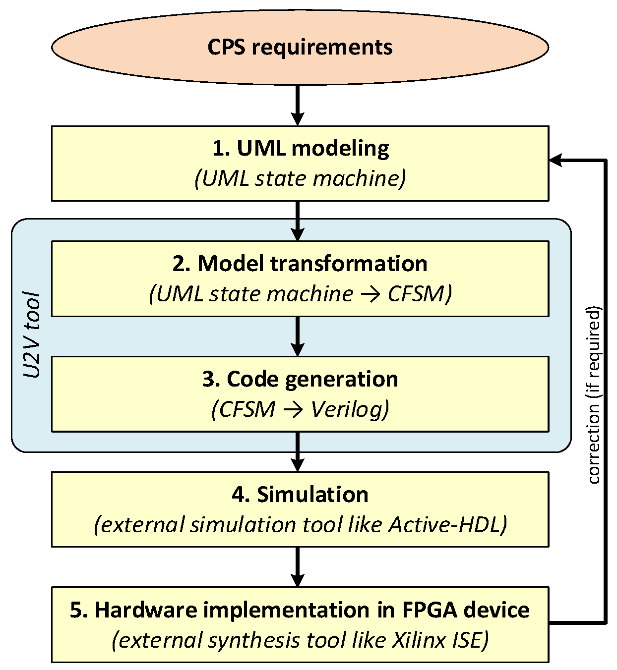
Figure 2.
An exemplary state machine diagram (the highest hierarchy level).
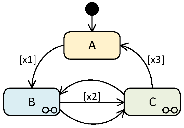
Figure 3.
A detailed state machine diagram from Figure 2 (the lowest hierarchy level).
Figure 3.
A detailed state machine diagram from Figure 2 (the lowest hierarchy level).
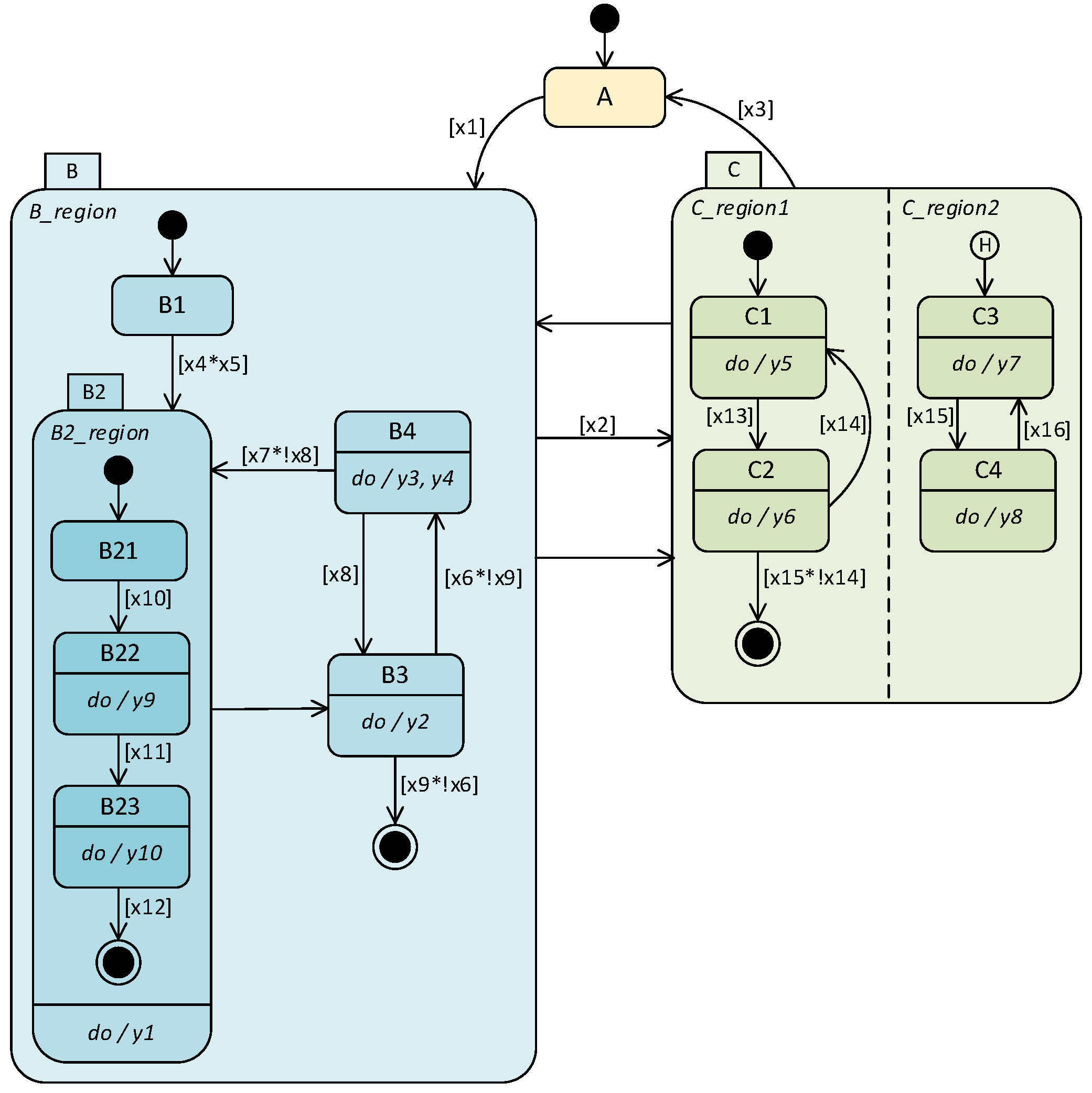
Figure 4.
The model transformation path from the CIM model to the code model.
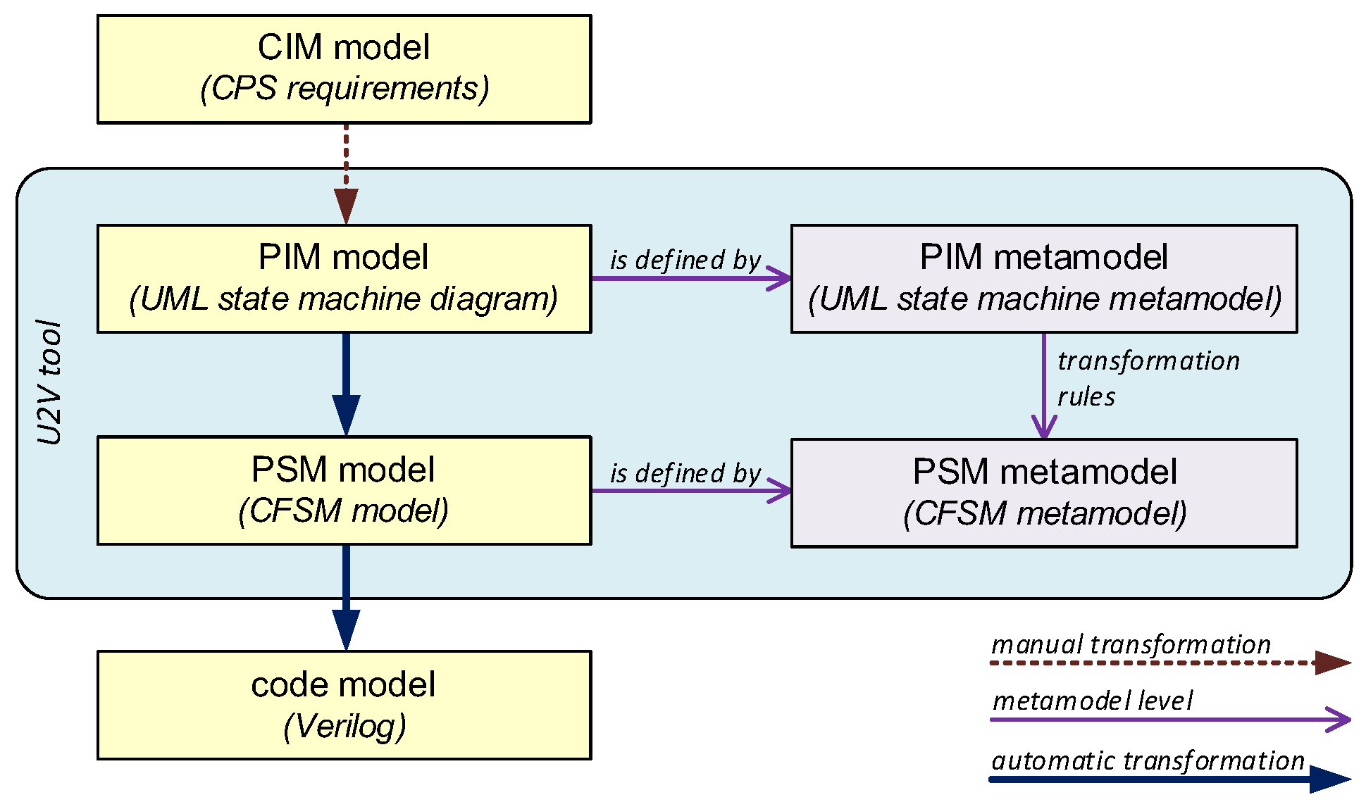
Figure 5.
A state machine decomposition algorithm (in the form of a UML activity diagram).

Figure 6.
Master FSM (Process).

Figure 7.
The exemplary slave FSMs: (a) B_region and (b) B2_region.
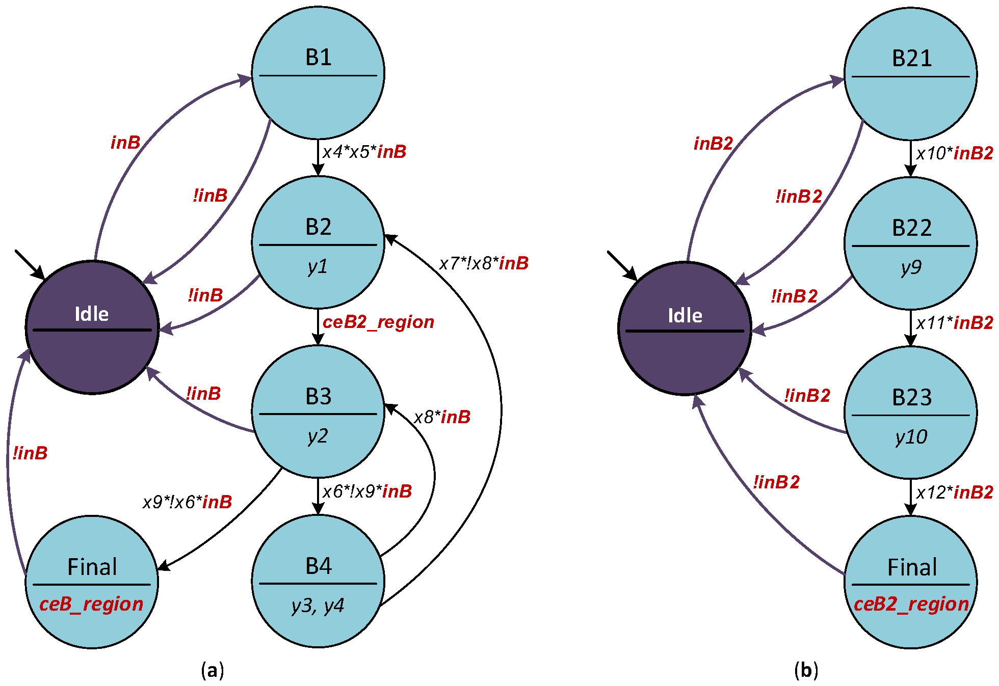
Figure 8.
The slave FSM (C_region2) with history mechanism.
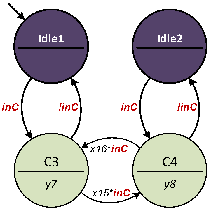
Figure 9.
The CFSM model.
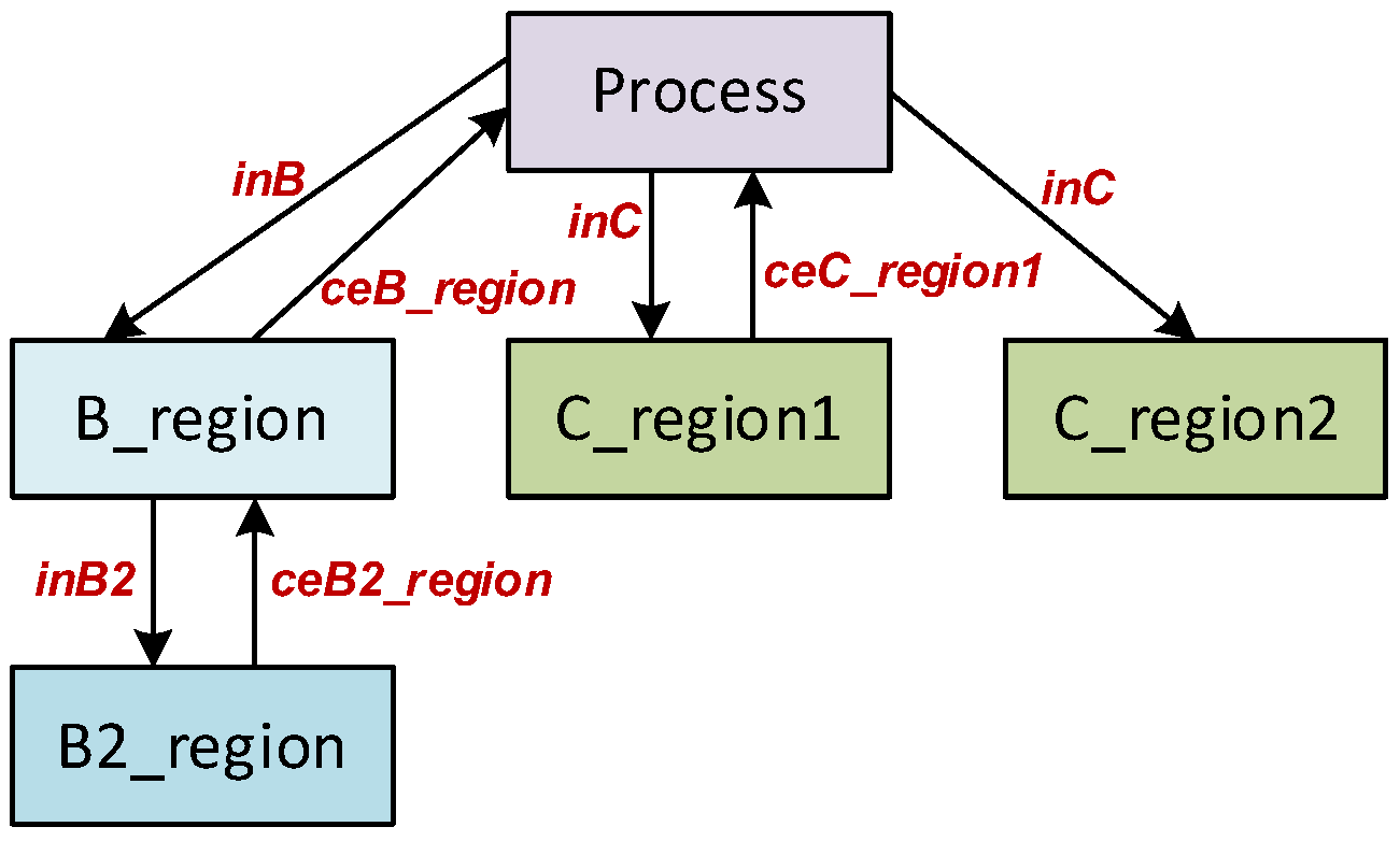
Figure 10.
SHS—a block diagram of the SHS controller.
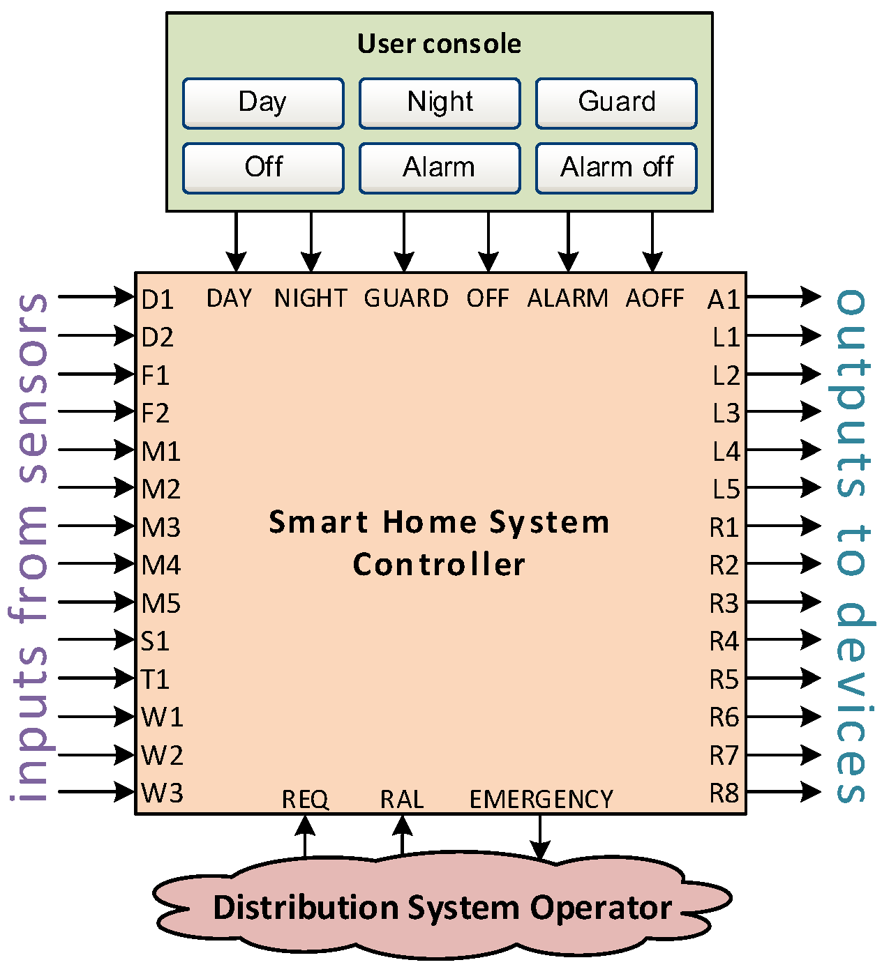
Figure 11.
SHS—a UML state machine diagram on the highest hierarchy level.
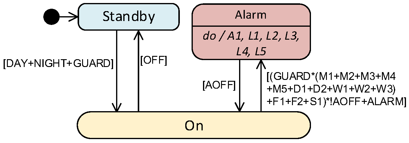
Figure 12.
SHS—a UML state machine diagram on the lowest hierarchy level.
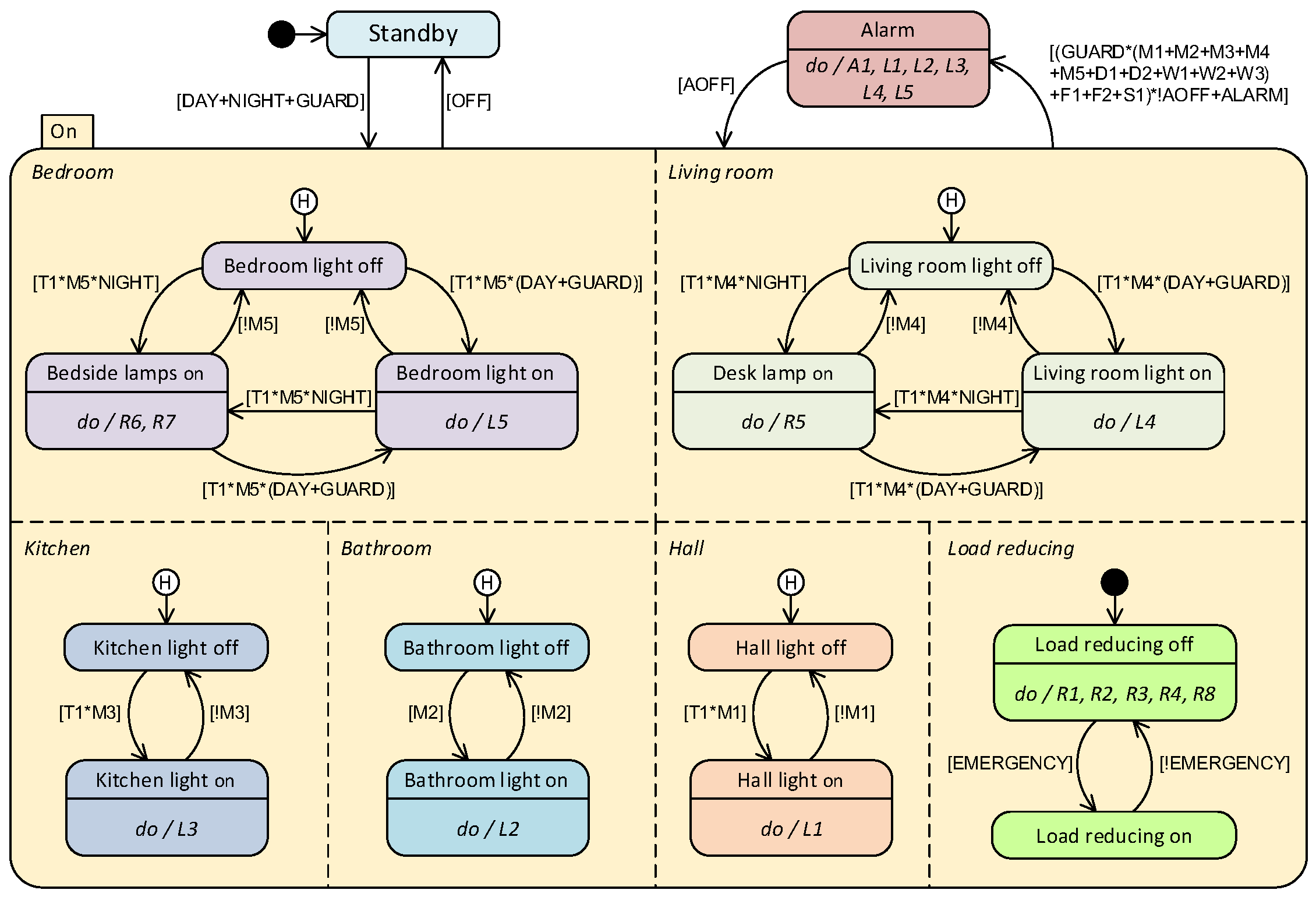
Figure 13.
SHS—the “Process” master FSM.
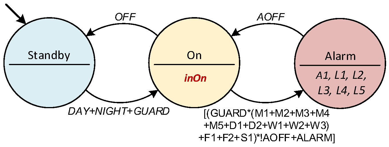
Figure 14.
SHS—(a) the “Bedroom” and (b) “Load-reducing” slave FSMs.

Figure 15.
SHS—the CFSM model.
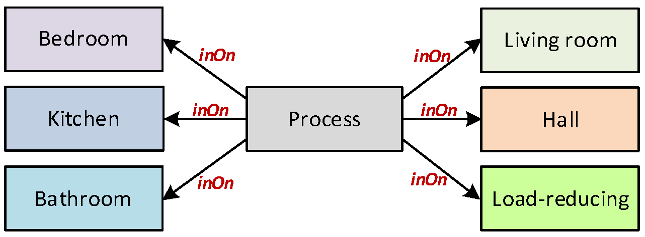
Figure 16.
SHS—simulation results.
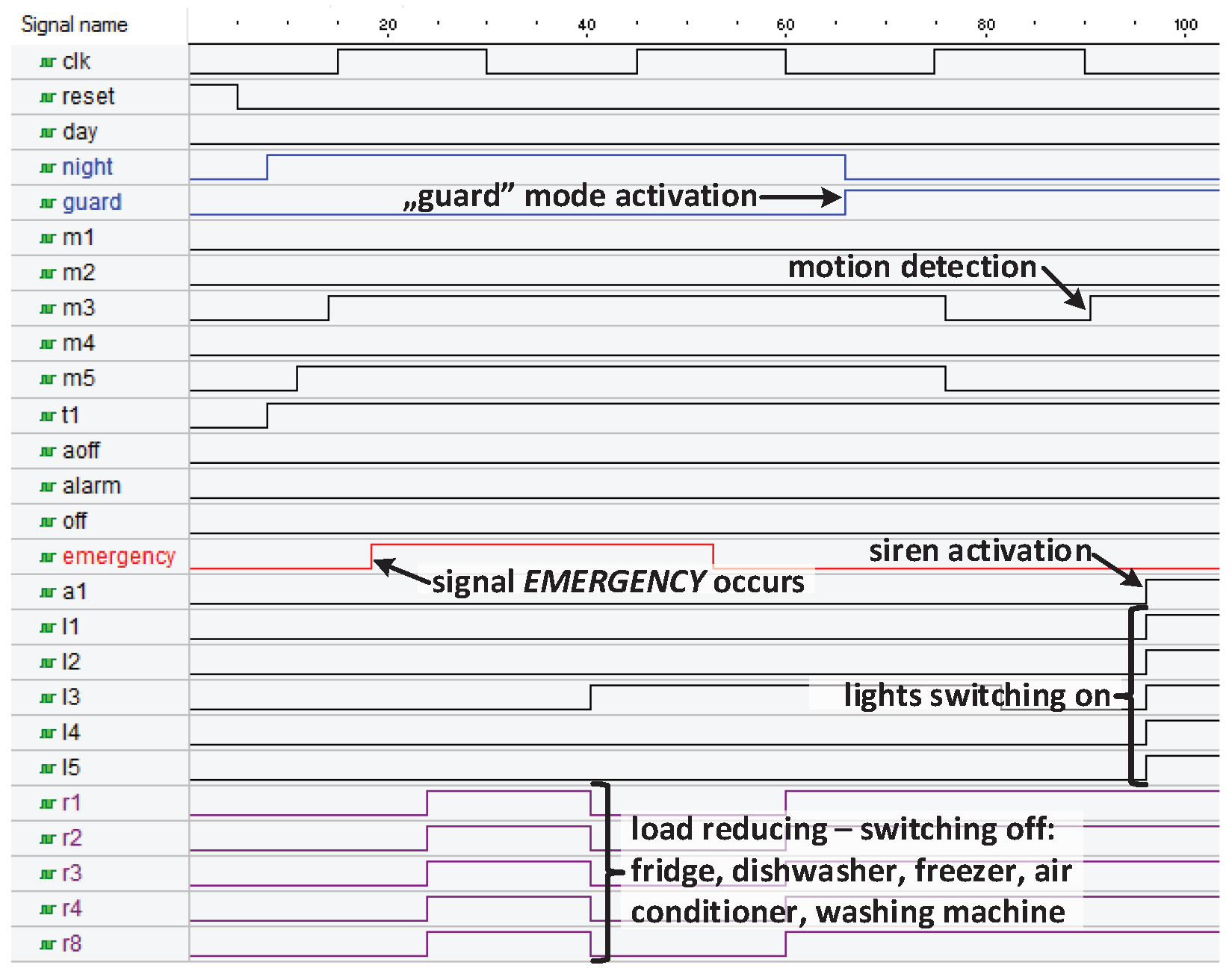
Figure 17.
SHS—a UML state machine diagram for the new version of the load-reducing module.
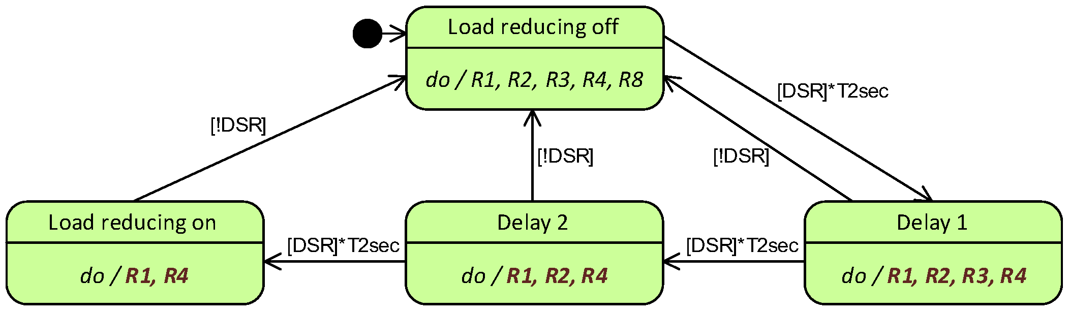
Figure 18.
SHS—the “Load reducing 2” slave FSM.
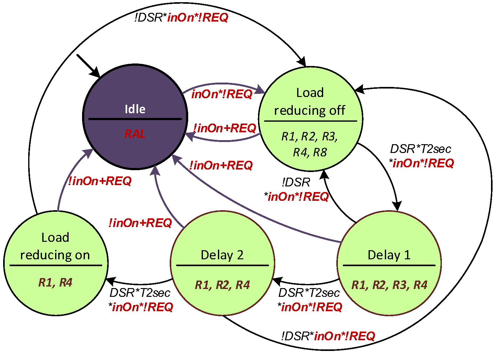
Figure 19.
SHS—dynamic partial reconfiguration of the SHS.

Table 1.
A comparison of the proposed method (including the U2V tool) with selected methods.
| Feature of the Method | [13] | [62] | [63] | [36] | [24] | [64] | U2V |
|---|---|---|---|---|---|---|---|
| Using models in UML 2.x | + | + | + | + | + | − | + |
| Using MDD approach | + | − | + | + | + | − | + |
| Support for hierarchical systems | + | + | + | − | + | + | + |
| Support for concurrent systems | + | + | + | − | + | + | + |
| Generating of system description in HDL | − | + | + | + | + | + | + |
| Output specification is synthesizable | − | + | − | + | + | + | + |
| Output specification is modular | − | − | − | − | − | − | + |
| Feature of the Method | MODEASY [24] | U2V |
|---|---|---|
| simple state | + | + |
| composite state | + | + |
| region | + | + |
| submachine state | − | − |
| external transitions | + | + |
| internal transitions | − | + |
| local transitions | − | − |
| initial pseudostate | + | + |
| shallow history pseudostate | + | + |
| deep history pseudostate | + | + |
| join pseudostate | + | − |
| fork pseudostate | + | − |
| junction pseudostate | + | − |
| choice pseudostate | + | − |
| terminate pseudostate | − | − |
| entry point | − | − |
| exit point | − | − |
| deferred events | − | − |
| entry behavior (in the state) | − | + |
| do-activity (in the state) | + | + |
| exit behavior (in the state) | − | + |
| triggers (in the transition) | + | + |
| guards (in the transition) | + | + |
| effects (in the transition) | + | + |
Disclaimer/Publisher’s Note: The statements, opinions and data contained in all publications are solely those of the individual author(s) and contributor(s) and not of MDPI and/or the editor(s). MDPI and/or the editor(s) disclaim responsibility for any injury to people or property resulting from any ideas, methods, instructions or products referred to in the content. |
© 2023 by the author. Licensee MDPI, Basel, Switzerland. This article is an open access article distributed under the terms and conditions of the Creative Commons Attribution (CC BY) license (https://creativecommons.org/licenses/by/4.0/).
Share and Cite
MDPI and ACS Style
Bazydło, G. Designing Reconfigurable Cyber-Physical Systems Using Unified Modeling Language. Energies 2023, 16, 1273. https://doi.org/10.3390/en16031273
AMA Style
Bazydło G. Designing Reconfigurable Cyber-Physical Systems Using Unified Modeling Language. Energies. 2023; 16(3):1273. https://doi.org/10.3390/en16031273
Chicago/Turabian StyleBazydło, Grzegorz. 2023. "Designing Reconfigurable Cyber-Physical Systems Using Unified Modeling Language" Energies 16, no. 3: 1273. https://doi.org/10.3390/en16031273
Note that from the first issue of 2016, this journal uses article numbers instead of page numbers. See further details here.